Article

Unraveling Microstructural Evolution and Mechanical Enhancements in LPBFed 316L Stainless Steel Under Ultrasonic Impact Treatment

School of Mechanical Engineering, Jiangsu University, Zhenjiang 212013, China
*
Authors to whom correspondence should be addressed.
Coatings 2026, 16(9), 1101; https://doi.org/10.3390/coatings16091101
Submission received: 22 July 2026 / Revised: 17 August 2026 / Accepted: 27 August 2026 / Published: 16 September 2026

Abstract

Laser powder bed fusion (LPBF) has emerged as a pivotal method for manufacturing intricate metal components using 316L stainless steel. Despite its effectiveness, LPBFed parts often suffer from coarse columnar grains, suboptimal surface finish, and mechanical properties. This study explores the transformative impact of ultrasonic impact treatment (UIT) on LPBFed 316L stainless steel, meticulously examining its effects on surface morphology, residual stress distribution, microstructure, and mechanical characteristics. The findings reveal a significant reduction in surface roughness due to UIT, accompanied by a remarkable conversion of residual tensile stress into compressive stress within the surface layer. Notably, the coarse columnar grains prevalent in the specimens undergo a substantial transformation, evolving into irregularly shaped equiaxed grains, characterized by reduced average grain size, elevated low-angle grain boundaries, and increased dislocation density. The ensuing microstructural evolution results in a substantial enhancement, with the maximum surface hardness reaching 303.4 HV, signifying a noteworthy 17.64% improvement compared to the original specimens. Additionally, significant improvements in both tensile strength and ductility are observed. These enhancements are primarily attributed to UIT-induced severe plastic deformation and dislocation strengthening, together with localized grain refinement and the conversion of tensile residual stress into compressive residual stress. This study not only unveils the underlying mechanisms of UIT but also underscores its pivotal role in augmenting the structural and mechanical integrity of LPBFed 316L stainless steel, offering valuable insights for advancing materials science and engineering applications.

1. Introduction

316L stainless steel, classified as ultra-low carbon austenitic stainless steel, exhibits remarkable attributes including exceptional corrosion resistance, outstanding strength and ductility, excellent biocompatibility, high resistance to oxidation, and efficient heat absorption. These superior characteristics have positioned it as a material of choice across diverse industries, including aerospace, petrochemical, biomedical, and automotive sectors [1,2,3]. In the realm of additive manufacturing, laser powder bed fusion (LPBF) stands out as a forefront technique, garnering significant attention for its precision and intricate component production using 316L stainless steel. In recent years, LPBF has emerged as a pivotal research focus, offering distinct advantages over traditional forming methods. Notably, LPBF enables the fabrication of highly complex parts, obviates the necessity for mold development, and drastically shortens manufacturing cycles [4,5,6,7].
In the realm of additive manufacturing, LPBF technology offers distinct advantages over traditional methods. However, the inherent thermal effects of the laser beam introduce a challenge in the form of significant residual tensile stresses within components. These residual tensile stresses can adversely affect the structural integrity of LPBFed components and may promote crack initiation and propagation under cyclic or mechanical loading [8]. Furthermore, the melting and solidification processes in LPBF contribute to suboptimal surface quality, rendering the components susceptible to defects such as pores and cracks [9,10]. The rapid melting and steep temperature gradients inherent in the LPBF process foster the formation of coarse columnar grains along the build direction, thereby inducing anisotropic mechanical properties in the manufactured metal components [11,12]. Previous studies have also systematically investigated the microstructure and mechanical properties of LPBF-fabricated 316L stainless steel, providing a useful reference for understanding the characteristic microstructural features and mechanical response of LPBF 316L [13].
In response to the challenges posed by residual stresses and surface defects in LPBF metal components, a range of post-processing methods, including heat treatment, hot isostatic pressing, and laser polishing, material design and composition optimization have been explored [14,15,16]. While heat treatment and hot isostatic pressing can effectively alleviate residual stresses and improve mechanical properties, they may not simultaneously address surface morphology and introduce beneficial compressive residual stresses [17]. Similarly, although laser polishing can enhance surface morphology and mechanical properties, it may not effectively mitigate residual tensile stresses within the components [18]. Although compositional design can improve the mechanical and tribological properties of materials through grain refinement and particle reinforcement [19], such strategies may increase manufacturing complexity and require precise control over reinforcement distribution. Consequently, the pursuit of innovative post-processing techniques has become imperative. Surface treatment methods, such as shot peening (SP), ultrasonic shot peening (USP), hammer peening (HP), laser shock peening (LSP), and ultrasonic impact treatment (UIT), have emerged as promising avenues [20,21,22,23,24]. These techniques, widely employed to enhance the performance of diverse metal components, hold substantial potential as novel post-processing approaches in the realm of additive manufacturing.
In the realm of surface treatment methods, UIT stands out as a burgeoning technology, harnessing high-amplitude ultrasonic energy and high-frequency mechanical impact to induce profound plastic deformation on metal surfaces. This innovative approach holds immense promise, particularly in the realm of additive manufacturing. Previous studies have showcased its transformative potential when combined with different manufacturing techniques. For instance, Zhang et al. [25] applied UIT to LPBFed Ti6Al4V alloy, revealing a significant reduction in residual stresses and the transformation of columnar grains into smaller equiaxed grains, thereby improving mechanical properties. Diao et al. [26] utilized UIT in wire arc additive manufacturing (WAAM) processes, demonstrating enhanced grain structure and mechanical properties in ER321 stainless steel. Cui et al. [27] explored Ultrasonic Surface Rolling Processing (USRP) on CrMnFeCoNi high-entropy alloy prepared using laser additive manufacturing (LAM), resulting in a nanocrystalline layer, enhancing hardness and wear resistance. Lv et al. [24] investigated double-sided UIT on Ti6Al4V alloy prepared using cold metal transfer additive manufacturing (CMTAM), leading to reduced surface roughness, transformed residual stresses, and improved tensile performance. Xu et al. [28] investigated the ultrasonic surface rolling process (USRP) applied to laser additively manufactured 316L stainless steel and demonstrated that static pressure and high-frequency ultrasonic impact jointly promoted plastic deformation and strain hardening, resulting in reduced surface roughness, increased microhardness, and induced compressive residual stresses. Maleki et al. [29] systematically compared several surface severe plastic deformation techniques, including ultrasonic shot peening (USP), ultrasonic nanocrystal surface modification (UNSM), severe shot peening (SSP), and laser shock peening (LSP), on laser powder bed fusion 316L stainless steel, revealing their effects on microstructure, residual stress, hardness, tensile properties, and fatigue behavior. More recently, Wang et al. [30] applied underwater ultrasonic impact treatment (UUIT) to direct metal deposited 316L stainless steel and reported the formation of a severely deformed layer with refined nano-grains and compressive residual stresses, together with enhanced surface hardness and tensile strength. Despite these advances, the depth-dependent relationship between UIT-induced plastic deformation, microstructural evolution, residual-stress redistribution, and mechanical-property enhancement in LPBFed 316L stainless steel remains insufficiently understood. In particular, the evolution of the original columnar grain structure, the development of low-angle grain boundaries (LAGBs) and dislocation structures, and their correlation with depth-dependent residual stress and hardness have not yet been systematically clarified. Furthermore, the mechanisms responsible for the simultaneous enhancement of strength and ductility after UIT require further investigation.
In this study, UIT is implemented as a post-processing methodology to systematically investigate the effects of UIT on the microstructural and mechanical evolution of 316L stainless steel samples produced through LPBF (referred to as LPBFed samples). The investigation delves into alterations in surface morphology, microstructure, residual stress, microhardness, and tensile properties before and after the application of ultrasonic impact treatment. Accordingly, this study focuses on the effects of UIT on surface morphology, residual stress, microstructural evolution, hardness, and tensile properties of LPBFed 316L stainless steel.

2. Material and Experimental Procedure

2.1. Materials

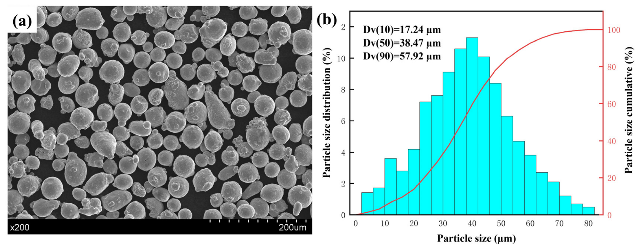
In this study, 316L stainless steel powder manufactured by AVIC Mait Additive Technology Co., Ltd. (Beijing, China) was selected as the raw material. The nominal chemical composition of the 316L stainless steel powder, as provided by the manufacturer, is listed in Table 1. The particle size distribution of the powder ranges from 2 to 83 µm, with specific percentiles indicated as D10 = 17.24 μm, D50 = 38.47 μm, and D90 = 57.92 μm, and an average particle size of 38.63 µm. Figure 1 illustrates the microstructure and particle distribution of the powder, depicting spherical particles with smooth surfaces, occasionally accompanied by a minor presence of satellite particles adhering to the surface. To maintain the integrity of the LPBF process and ensure the quality of the final specimens, the powder underwent pre-processing by drying at 100 °C for 5 h in a vacuum drying oven, thus mitigating potential interference in powder spreading.

2.2. Sample Fabrication

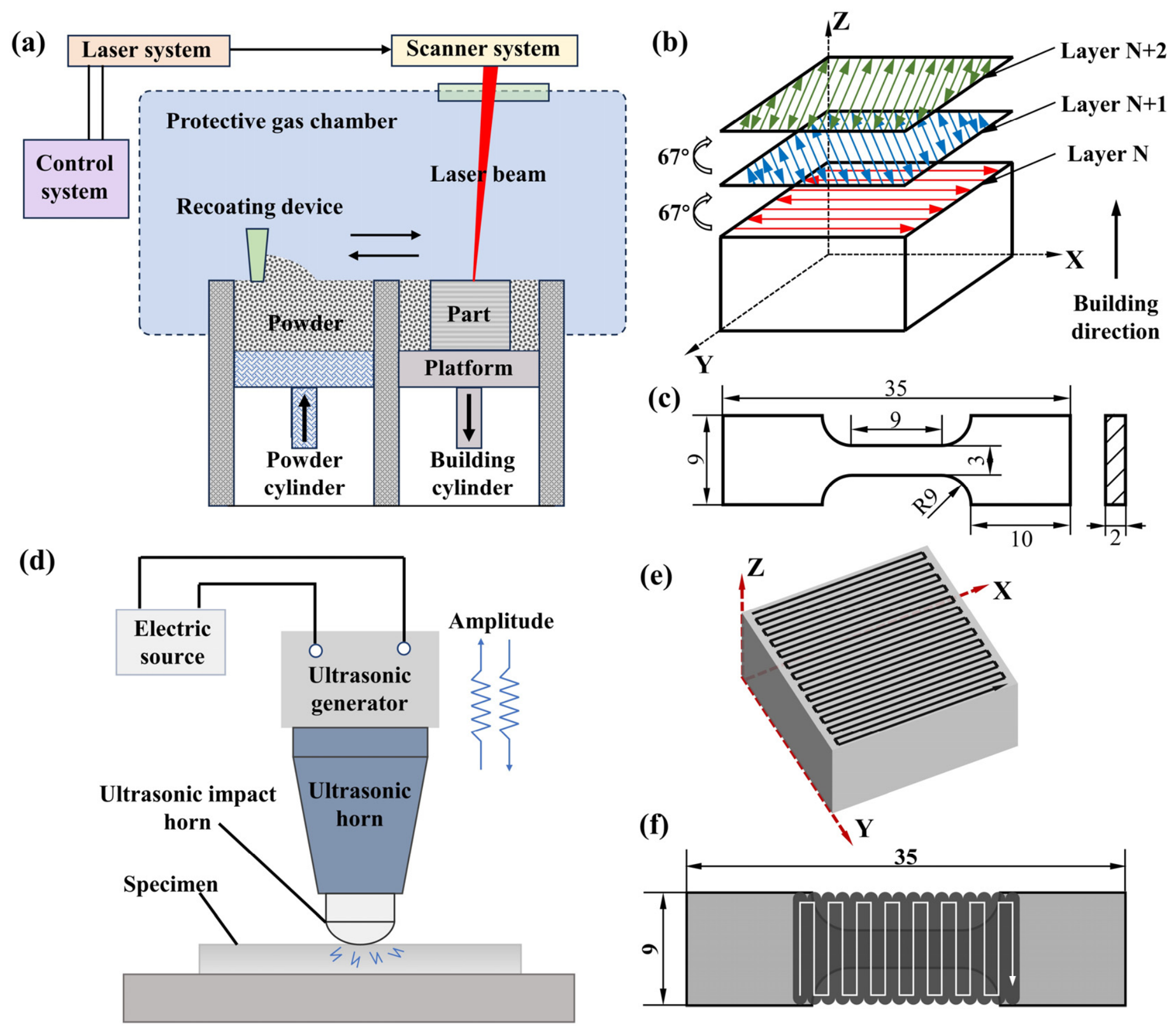
In this study, the experimental setup employed the HBD-150 laser selective melting system from China for LPBF metal printing. The laser unit possessed a maximum power of 500 W, operating at a wavelength of 1064 nm, with a circular beam exhibiting a diameter of 65 µm. The energy distribution followed a Gaussian pattern. The system enabled the fabrication of parts with dimensions reaching 150 mm × 150 mm × 200 mm. The processing process is visually outlined in Figure 2a. Referring to prior parameter explorations [31], the specific process parameters utilized are detailed in Table 2. The adjacent layer angle during printing was set at 67°, and the scanning strategy is elucidated in Figure 2b. To ensure optimal forming quality and prevent oxidation, it was imperative to regulate the oxygen content during the process. To achieve this, high-purity argon gas with a purity of 99.99% served as the protective atmosphere, maintaining the oxygen content below 0.01% throughout the forming process. The printed cube samples were of dimensions 8 mm × 8 mm × 8 mm3, while the tensile test samples exhibited the dimensions illustrated in Figure 2c. Each parameter set yielded three tensile test samples, with the build orientation being perpendicular to the loading direction in the tensile test configuration.
In this experimental setup, the ultrasonic impact system utilized was the JZ-5020-4DX model from Hangzhou Jinyuan Ultrasonic Technology Co., Ltd., Hangzhou, China, comprising an ultrasonic generator and an ultrasonic impact gun. The system’s configuration is illustrated in Figure 2d. After the LPBF processing, the resulting samples underwent meticulous preparation. They were precisely sectioned using wire cutting, followed by thorough polishing of the surfaces. Subsequently, the processed samples were subjected to ultrasonic cleaning in anhydrous ethanol. In the subsequent step, these meticulously cleaned samples were securely clamped and subjected to ultrasonic impact treatment. Preliminary trials, together with the reported operating conditions in previous studies and the applicable range of the UIT equipment, were used to identify an appropriate treatment window. Based on these trials, an amplitude of 10 μm, a static load of 50 N, a vibration head diameter of 3 mm, and a scanning speed of 1 mm/s were selected and fixed for the systematic investigation in this work. Different UIT conditions may produce different microstructural and mechanical responses by altering the impact intensity and plastic deformation. Higher impact intensity can promote dislocation accumulation, grain refinement, and compressive residual stress, whereas excessive impact may cause severe surface deformation. Therefore, the selected parameters were kept constant to systematically investigate the effects of UIT on LPBFed 316L stainless steel. During the ultrasonic impact treatment, both cube samples and tensile test samples followed an S-shaped path, with specific processing regions delineated in Figure 2e,f.

2.3. Material Characterization Tests

A VK-X1000 laser confocal microscope (Keyence, Osaka, Japan) was employed to meticulously assess the surface morphology and roughness of the samples both before and after UIT. The surface phase composition of the cube samples was elucidated through X-ray diffraction (XRD). The main technical parameters of the equipment include the following: SmartLab type diffractometer (Rigaku Corporation, Akishima, Japan), Cu radiation source, 2θ scanning range 10–100°, scanning rate 2°/min, data acquisition step size 0.02°. For cross-sectional SEM characterization, the specimens were sectioned perpendicular to the treated surface using wire electrical discharge machining (wire EDM) and then mounted. The cross-sections were sequentially ground using 400–2000 grit SiC abrasive papers and polished with a 0.05 μm colloidal silica suspension. After polishing, the specimens were etched in a solution containing 20 g FeCl3, 50 mL HCl, and 100 mL H2O before SEM observation. Subsequently, the etched samples were carefully wiped with anhydrous ethanol and dried. The cross-sectional microstructure of the samples was thoroughly examined using a JSM-7800F field emission scanning electron microscope (SEM) (JEOL Ltd., Akishima, Japan) equipped with electron backscatter diffraction (EBSD). The microhardness distribution on the surface and in the depth direction of the samples before and after ultrasonic impact was precisely measured utilizing a 36S10 microhardness tester, employing a 100 GF load and a loading time of 10 s. In the surface plane, ten points were measured along one direction every 1 mm within the enhanced area, with three readings taken at each point. The microhardness value in that direction was determined as the average. For microhardness measurement in the depth direction of the sample, test points were selected at 50 µm intervals along the depth direction from 0 to 0.6 mm from the surface. At each depth, three random points were chosen, and the average value was calculated as the microhardness value at that specific test point. The distribution of residual stress on the surface and in the depth direction of the samples before and after ultrasonic impact was meticulously examined using an X-350A residual stress measuring instrument. The methodologies for measuring both surface and depth-direction residual stress mirrored those employed in microhardness testing. Tensile tests at room temperature were carried out utilizing a UTM4104 electronic universal testing machine, operating at a tensile speed of 1 mm/min. The resulting fracture morphology of the tensile specimens was comprehensively observed using SEM, providing valuable insights into the mechanical properties and structural alterations induced by the ultrasonic impact treatment.

3. Results

3.1. Surface Morphology Analysis

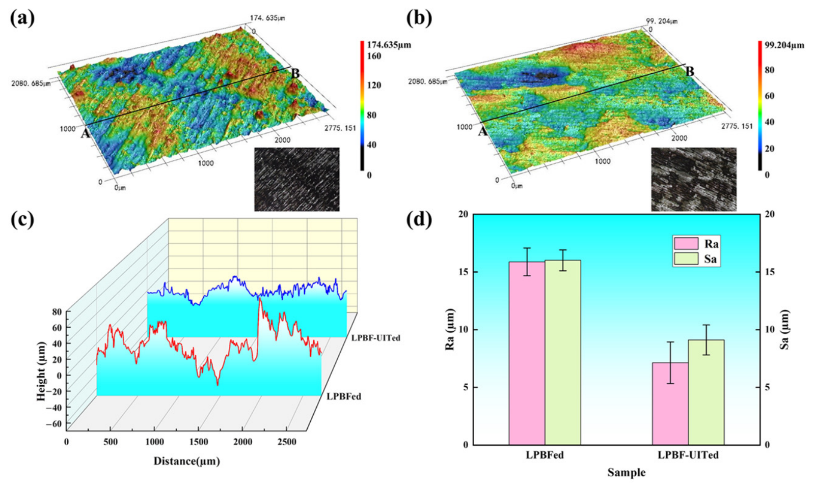
The surface characteristics of LPBFed and LPBF-UITed samples were meticulously analyzed, as illustrated in Figure 3. The LPBF process inherently introduces surface irregularities due to flow-driven mass transfer within the melt pool, influenced by forces such as surface tension, Marangoni effect, buoyancy, and gravity. These forces result in an uneven surface marked by peaks and valleys formed by the solidification of the Gaussian laser beam. Moreover, the surface often exhibits pores and unfused particles, which are typical features of LPBFed parts [32].
Under the influence of UIT, the sample’s surface undergoes significant plastic de-formation, redistributing material from the peaks to the valleys, thereby mitigating the unevenness observed in the LPBFed sample. To quantify the impact of UIT on surface roughness, two-dimensional profiles of the LPBFed and LPBF-UITed samples along the A–B direction were analyzed, as delineated by the black lines in Figure 3a,b. Here, A and B denote the starting and ending points of the profile measurement line, respec-tively, and the red and blue curves in Figure 3c represent the LPBFed and LPBF-UITed samples, respectively. The LPBFed sample displayed notable fluctuations in its two-dimensional contour, whereas UIT noticeably reduced these fluctuations, leading to a smoother surface. The surface roughness parameters, Sa and Ra, are graphically presented in Figure 3d. The LPBFed sample exhibited relatively low surface smoothness, characterized by Ra and Sa values of 15.88 µm and 16.01 µm, respectively. In contrast, the LPBF-UITed sample demonstrated improved surface quality, yielding Ra and Sa values of 7.14 µm and 9.11 µm, respectively. Notably, ultrasonic impact-induced plastic deformation resulted in a substantial reduction in surface roughness, with Ra and Sa values decreasing by 55.03% and 43.09%, respectively. These findings underscore the effectiveness of ultrasonic impact treatment in enhancing the surface quality of LPBFed components.

3.2. XRD Analysis

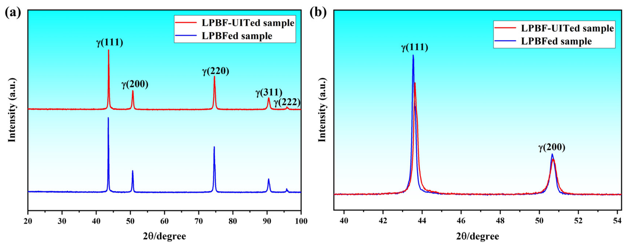
XRD spectra were used to characterize the phase composition and crystallographic changes of the LPBFed and LPBF-UITed samples, as shown in Figure 4. The LPBFed sample primarily consists of the γ-austenite phase, and no new diffraction peaks are observed after UIT, indicating that no obvious phase transformation occurs. As shown in Figure 4b, the γ(111) and γ(200) peaks shift from 43.54° to 43.64° and from 50.66° to 50.72°, respectively, corresponding to increases of 0.10° and 0.06°. According to Bragg’s law, 2dsinθ = λ, the corresponding interplanar spacings decrease from 2.0769 to 2.0724 Å for γ(111) and from 1.8005 to 1.7985 Å for γ(200), corresponding to reductions of 0.22% and 0.11%, respectively. These quantitative results indicate a slight lattice contraction after UIT, consistent with the compressive lattice strain induced by UIT and the compressive residual stress measured after treatment [24]. The diffraction intensities of the γ(111) and γ(200) peaks also decrease after UIT, which may be related to microstrain, lattice distortion, grain refinement, and changes in crystallographic texture [33].

3.3. Residual Stress

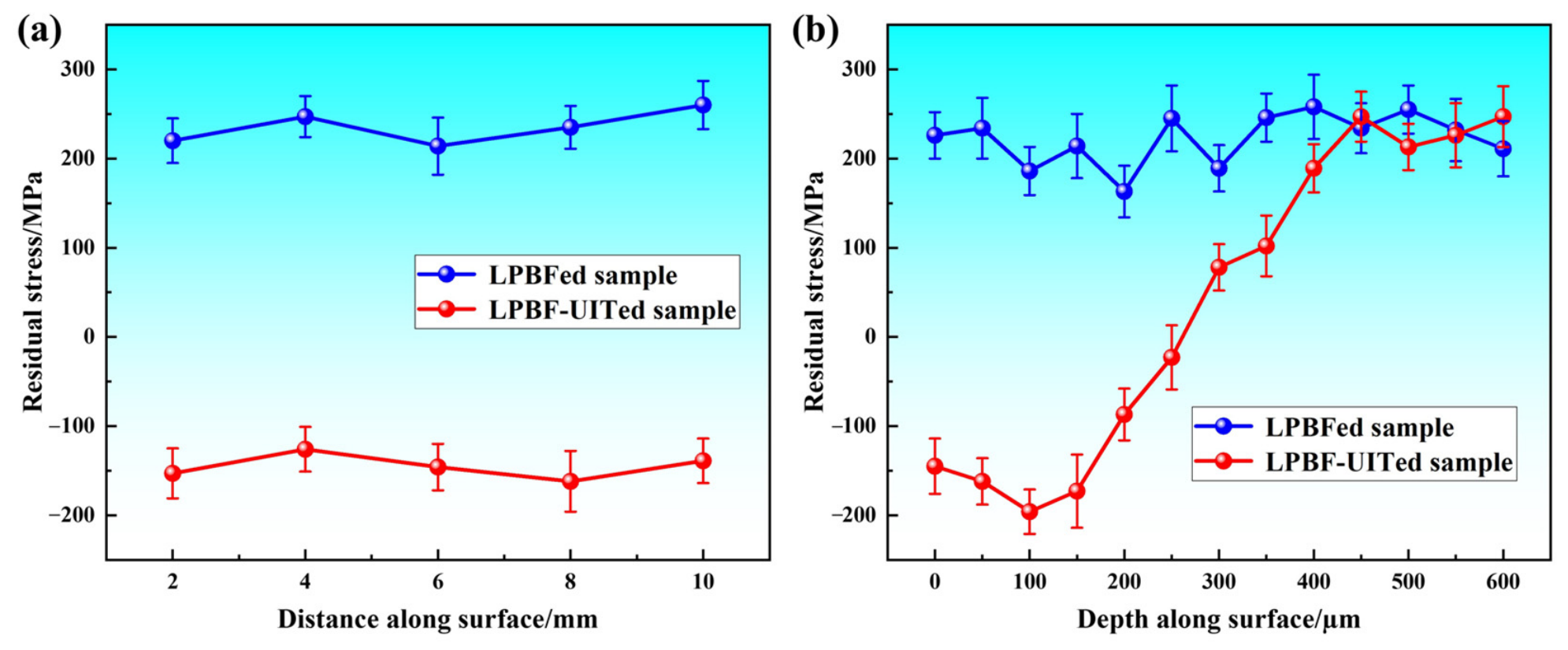
The residual stress distributions in the surface and depth directions of the LPBFed and LPBF-UITed samples are shown in Figure 5, where positive and negative values represent tensile stress and compressive stress, respectively. For the LPBFed sample, the high thermal gradients and rapid cooling during the LPBF process play a crucial role in the formation of residual tensile stress in the LPBFed sample [34,35]. As shown in Figure 5a, the average residual stress value on the surface of the LPBFed sample is 235.2 MPa. After UIT, the surface residual stress changes from tensile to compressive, with an average value of −145.3 MPa. This transformation is mainly attributed to the severe plastic deformation induced by ultrasonic impacts. The constrained deformation between the UIT-affected surface layer and the underlying material generates compressive residual stress during unloading. Meanwhile, the increased LAGB fraction and KAM values indicate enhanced dislocation-related plastic deformation and strain hardening, which further contribute to the retention of compressive residual stress. As shown in Figure 5b, the magnitude of the residual compressive stress in the LPBF-UITed sample initially increases and then decreases with increasing depth, reaching a maximum value of −196.2 MPa at a depth of 0.1 mm. This depth-dependent distribution indicates that the intensity of UIT-induced plastic deformation is not uniform but gradually decreases with increasing depth. The corresponding reduction in the deformation-induced microstructural changes results in a gradual decrease in the magnitude of the compressive residual stress. At a depth of approximately 0.45 mm, the residual stress approaches that of the LPBFed sample, indicating that the significant effect of UIT is mainly confined to the near-surface region.

3.4. Microstructure Characterization

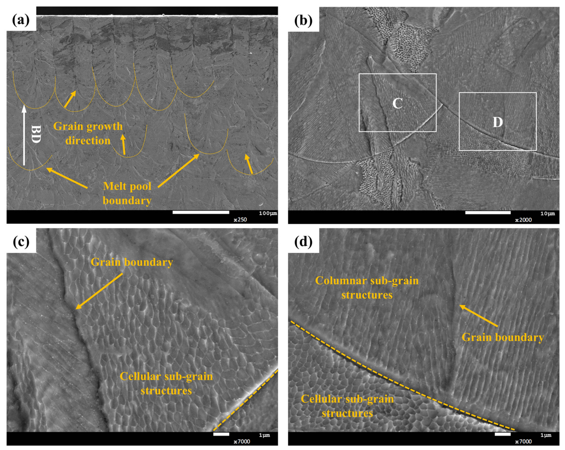
In Figure 6, the microstructure of the LPBFed sample is presented in a cross-section parallel to the build direction (BD), as indicated by the white arrows in Figure 6a. This cross-sectional view showcases a distinctive arrangement of “scale-like” melt pools, closely packed with overlapping boundaries (yellow dashed lines), a manifestation of Marangoni convection occurring within the melt pools during LPBF processing [31]. Notably, the build direction exhibits long columnar grains, growing perpendicular to the melt pool boundaries (indicated by yellow arrows), a characteristic phenomenon observed in LPBFed parts. The formation of these elongated columnar grains is attributed to temperature gradients, the preferred growth direction of austenite during solidification, and epitaxial grain growth from the previous layer [36,37]. Figure 6b reveals a cellular subgrain structure within the columnar grains, emphasizing the intricate internal organization of the material. Additionally, the overlapping region between adjacent melt pools exhibits a similar cellular subgrain structure, as depicted in Figure 6c. Furthermore, the base of the melt pools in the LPBFed sample displays a columnar subgrain structure (Figure 6d), with the columns oriented perpendicular to the melt pool boundaries, aligning with the direction of heat flow [18]. These detailed microstructural features offer valuable insights into the intricate processes governing the formation of LPBFed components, shedding light on the complex interplay of thermal gradients, solidification dynamics, and grain growth mechanisms in additive manufacturing.
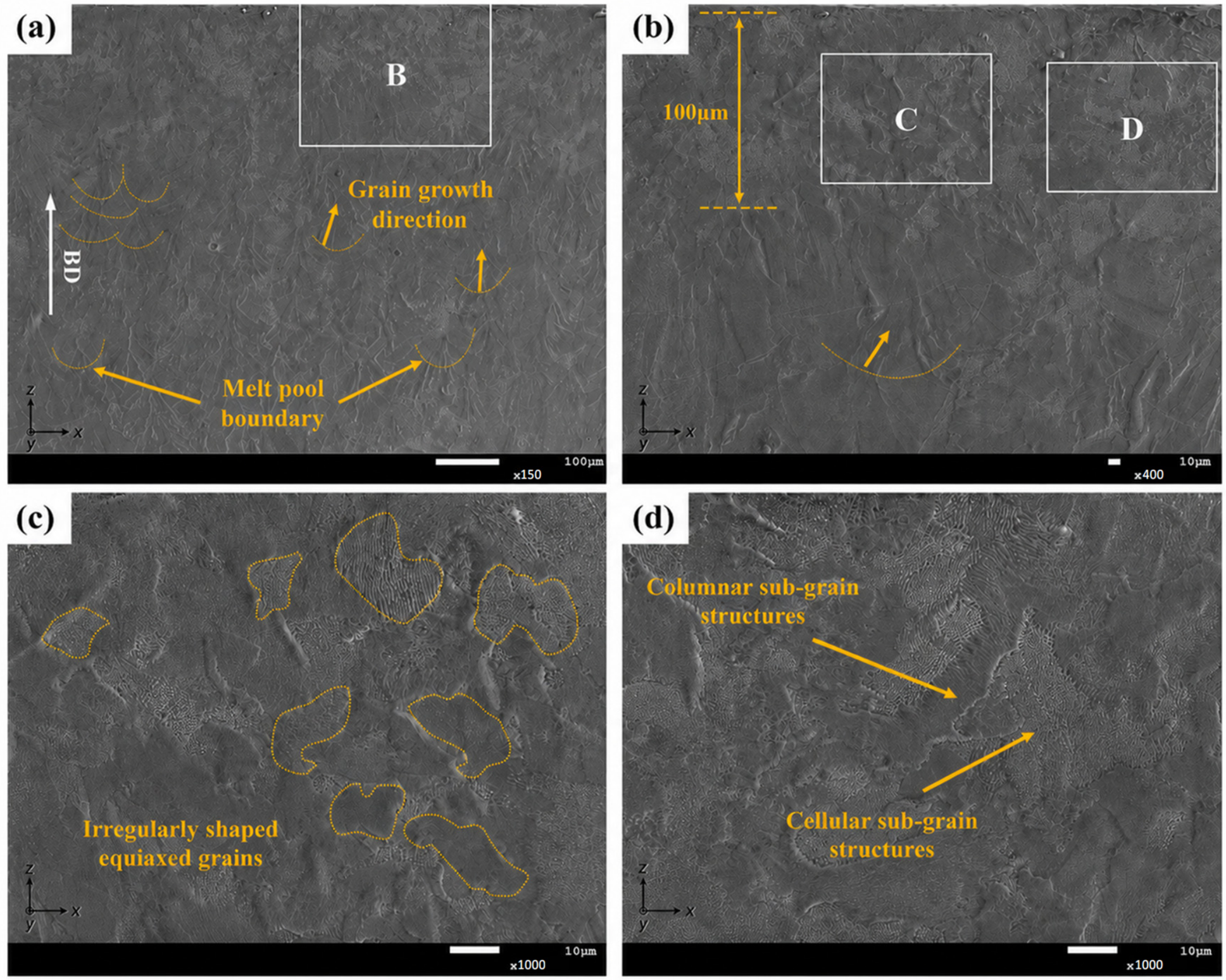
In Figure 7, the microstructure of the LPBF-UITed sample in a cross-section parallel to the build direction (BD) is elucidated, marked by the white arrows in Figure 7a. As depicted in Figure 7b, UIT induces a pronounced plastically deformed layer approximately 100 µm in depth near the surface. Within this layer, the boundaries of the melt pools, previously visible, become obscured. Beneath this plastic deformation layer, the well-defined boundaries of the melt pools persist, along with columnar grains growing perpendicular to these boundaries. Upon closer examination at higher magnification, noticeable changes in grain morphology are observed within the plastically deformed layer, including the appearance of irregularly shaped and more equiaxed grain features, as shown in Figure 7c,d. These morphological changes are accompanied by columnar and cellular subgrain structures, indicating substantial microstructural modification induced by UIT [38]. These observations underscore the transformative impact of ultrasonic impact treatment on the surface morphology and internal microstructure of LPBFed samples, shedding light on the underlying mechanisms of severe plastic deformation and grain structure evolution induced by this novel post-processing technique.
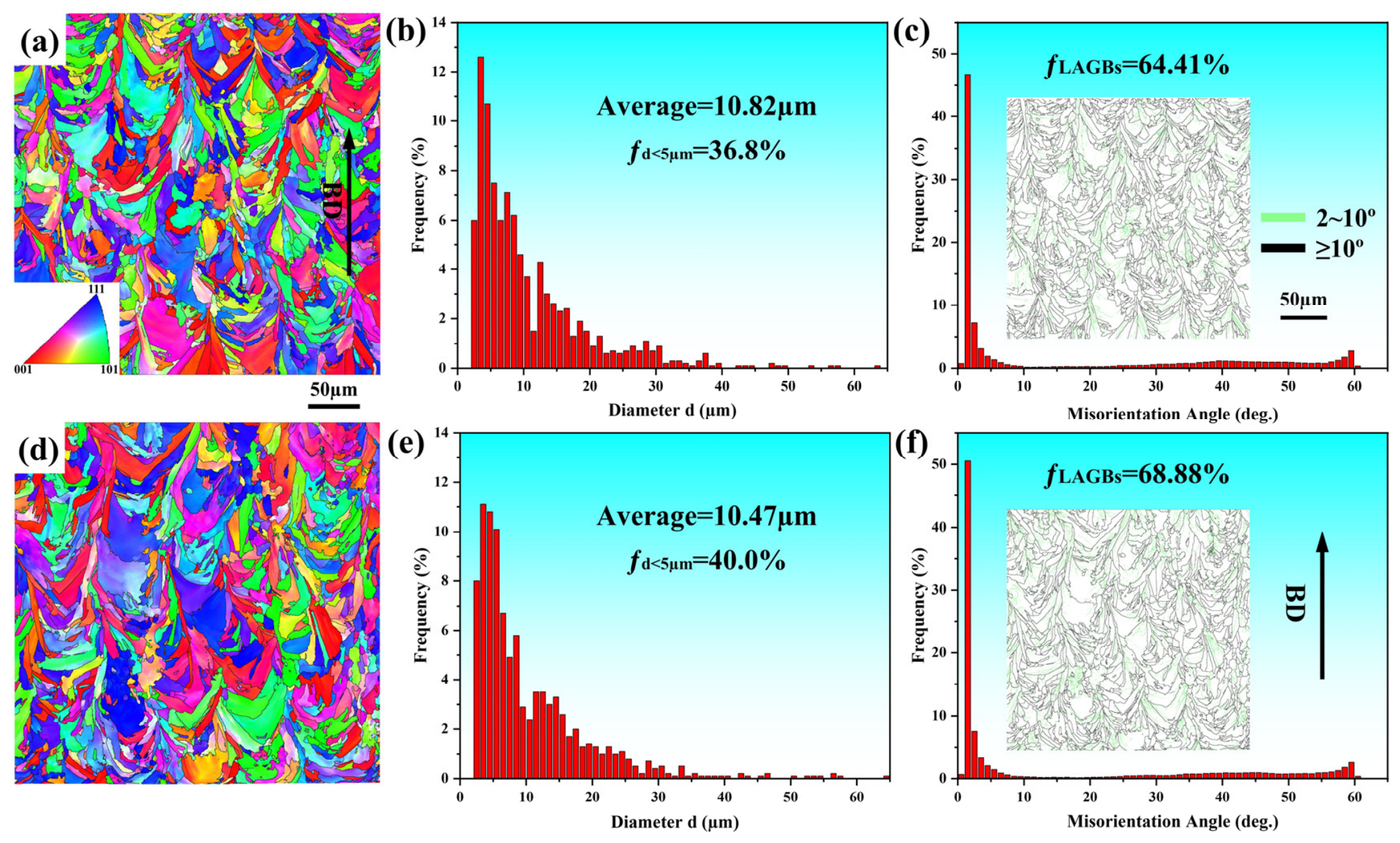
In Figure 8, the EBSD inverse pole figure (IPF) maps, grain size distributions, and misorientation angle distributions in cross-sections beneath the intense plastic deformation layer are presented for both the LPBFed and LPBF-UITed samples. As depicted in Figure 8a,d, both samples exhibit characteristic columnar crystal morphology, a result of the influential role of heat flux in guiding grain growth during the LPBF process. Notably, Figure 8b,e show that, in this region beneath the plastically deformed layer, the average grain size of the LPBFed sample is 10.82 µm, with 36.8% of grains smaller than 5 µm, whereas that of the LPBF-UITed sample decreases slightly to 10.47 µm, corresponding to a 3.24% reduction. Furthermore, the proportion of grains smaller than 5 µm in the LPBF-UITed sample increases to 40.0%. This slight reduction in grain size may be associated with the plastic deformation and grain subdivision induced by UIT. Examining grain boundaries and misorientation distributions, both samples display a significant presence of low-angle grain boundaries (LAGBs). Following UIT, the proportion of LAGBs rises from 64.41% in the LPBFed sample to 68.88% in the LPBF-UITed sample. This increase is primarily attributed to grain refinement, particularly owing to subgrains formed during the intense plastic deformation induced by UIT. Moreover, the increased LAGB fraction is indicative of enhanced dislocation accumulation and the development of dislocation-related substructures after UIT [33].
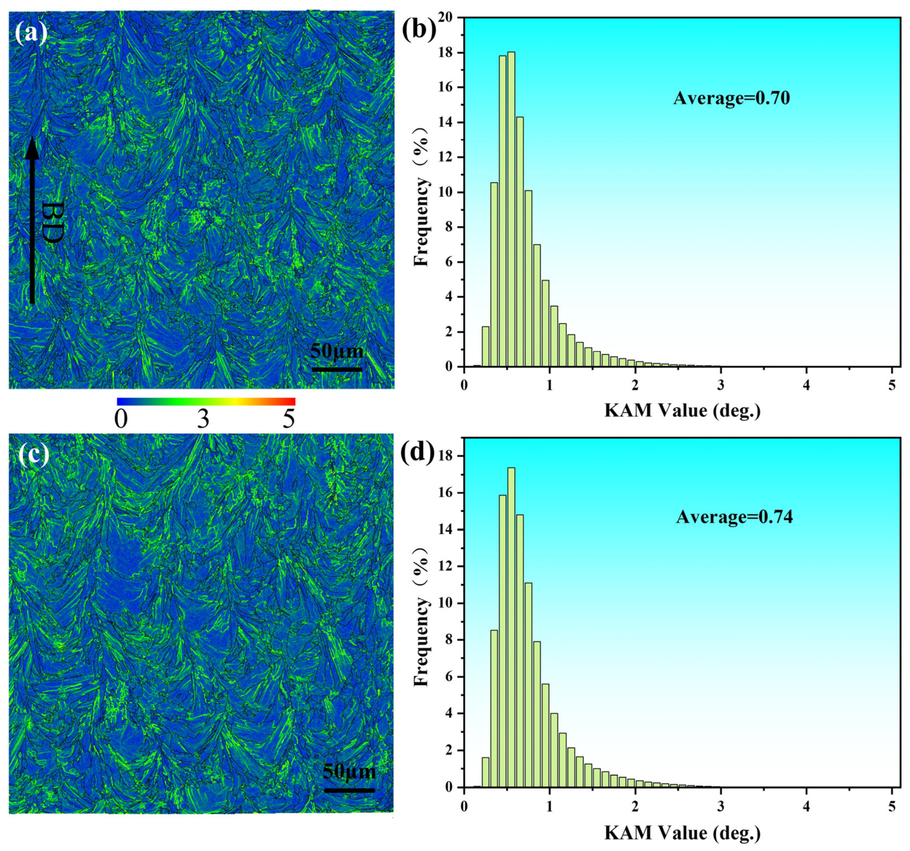
In Figure 9, Kernel Average Misorientation (KAM) maps and KAM value distributions are presented for both the LPBFed and LPBF-UITed samples. These maps serve as a valuable tool for assessing local orientation errors within the grains. As depicted in Figure 9a,c, high KAM values tend to cluster around the boundaries of the melt pools in the LPBFed sample. In stark contrast, the LPBF-UITed sample exhibits a reduction in deformation severity with increasing depth, leading to an augmentation of high KAM values near the surface layer. Notably, the KAM values display a gradient distribution. As illustrated in Figure 9b,d, the average KAM value increases from 0.70 in the LPBFed sample to 0.74 in the LPBF-UITed sample. The increase in KAM is consistent with the increased proportion of LAGBs, suggesting enhanced local lattice distortion and dislocation accumulation after UIT. Under the influence of UIT, dislocations within grains aggregate to form dislocation walls, impeding the motion of dislocations towards grain boundaries. With the continued accumulation of dislocations, these dislocation walls gradually evolve into LAGBs [39,40]. The higher KAM values near the UIT-treated surface indicate enhanced local lattice misorientation and plastic deformation, which is consistent with increased dislocation activity and the development of dislocation-related substructures.

3.5. Hardness

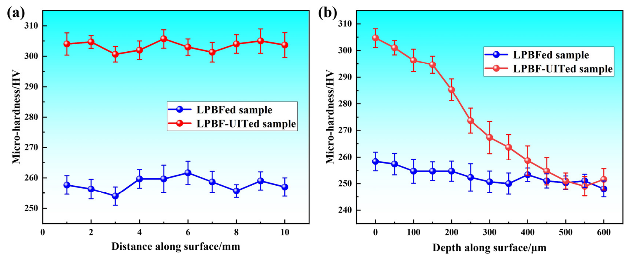
In Figure 10, the microhardness distributions along the surface and depth directions of the LPBFed and LPBF-UITed samples are presented. For the LPBFed sample, the surface microhardness ranges from 254 to 262 HV, with an average value of 257.9 HV. Following UIT, the average surface microhardness of the LPBF-UITed sample increases to 303.4 HV, corresponding to an enhancement of 17.64% compared with the LPBFed sample. Intriguingly, as shown in Figure 10b, the microhardness of the LPBFed sample exhibits only slight fluctuations with increasing depth, whereas that of the LPBF-UITed sample gradually decreases with increasing depth. At depths beyond approximately 500 μm, the microhardness of the LPBF-UITed sample approaches that of the LPBFed sample, indicating that UIT produces a hardened layer with an effective depth of approximately 500 μm. The pronounced hardness enhancement is associated with the severe plastic deformation induced by UIT and the resulting defect-related strengthening in the affected surface region. In particular, the increased dislocation accumulation and lattice distortion, as evidenced by the increased LAGB fraction and KAM value, contribute substantially to the enhanced hardness. The formation of irregular equiaxed grains and the accompanying grain refinement may provide an additional strengthening contribution.

3.6. Tensile Property and Fractural Morphology

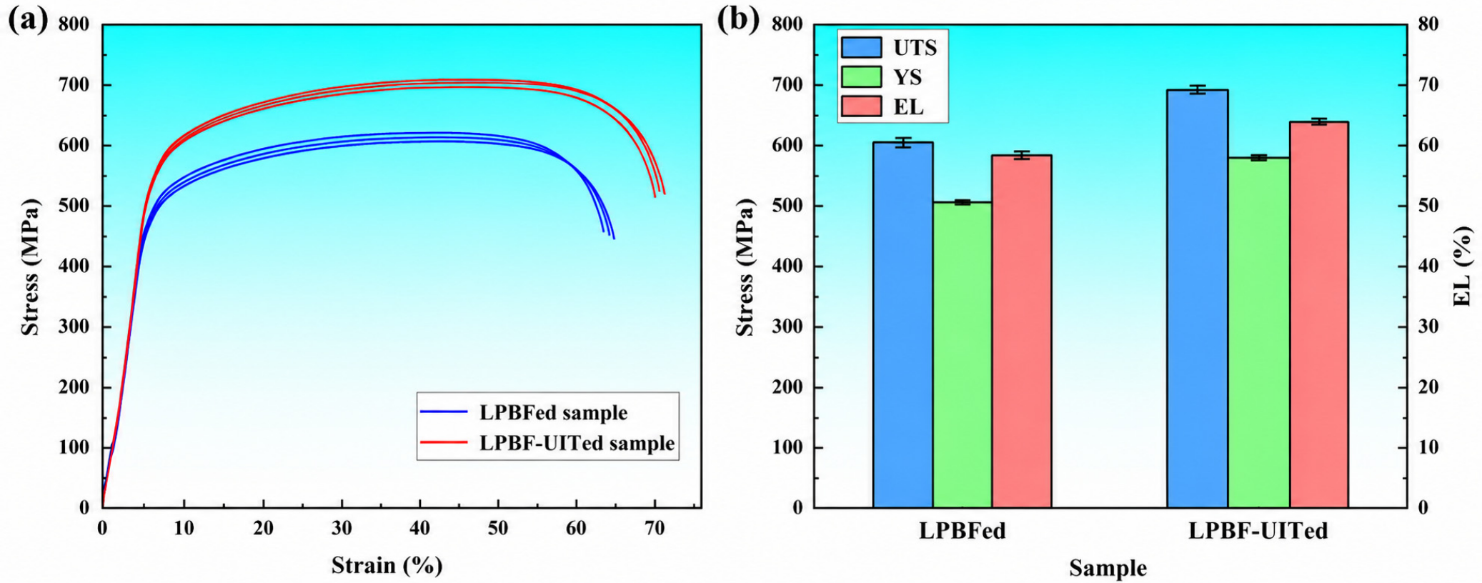
In Figure 11a, the intricate interplay of tensile stress–strain behaviors in the LPBFed and LPBF-UITed samples is meticulously unveiled, casting light on their mechanical responses at room temperature when subjected to tensile loading perpendicular to the build direction. Figure 11b succinctly encapsulates the quintessence of these observations, encapsulating the ultimate tensile strength (UTS), yield strength (YS), and elongation (EL) of both the LPBFed and LPBF-UITed samples. Noteworthy is the observation that, as the stress–strain curves of both the LPBFed and LPBF-UITed samples approach their zenith, they do not succumb to immediate fracture. Instead, they undergo a distinctive necking stage preceding ultimate failure. The LPBFed sample manifests UTS, YS, and EL values of 605.60 ± 15.32 MPa, 501.85 ± 12.14 MPa, and 46.20 ± 2.10%, respectively. Contrastingly, the LPBF-UITed sample exhibits a tangible upswing, boasting UTS, YS, and EL metrics of 693.25 ± 12.80 MPa, 578.40 ± 10.95 MPa, and 54.50 ± 2.35%, respectively. For comparison, the tensile properties obtained in this study were compared with those reported for LPBF-fabricated 316L stainless steel [13]. The literature reported a yield strength of 458.18 ± 41.81 MPa, an ultimate tensile strength of 669.92 ± 18.68 MPa, and an elongation of 22.41 ± 2.68% for LPBF 316L. In the present study, the LPBFed sample showed a yield strength of 501.85 ± 12.14 MPa, an ultimate tensile strength of 605.60 ± 15.32 MPa, and an elongation of 46.20 ± 2.10%. After UIT, these values increased to 578.40 ± 10.95 MPa, 693.25 ± 12.80 MPa, and 54.50 ± 2.35%, respectively. The results demonstrate that UIT effectively improves both the strength and ductility of LPBF-fabricated 316L stainless steel.
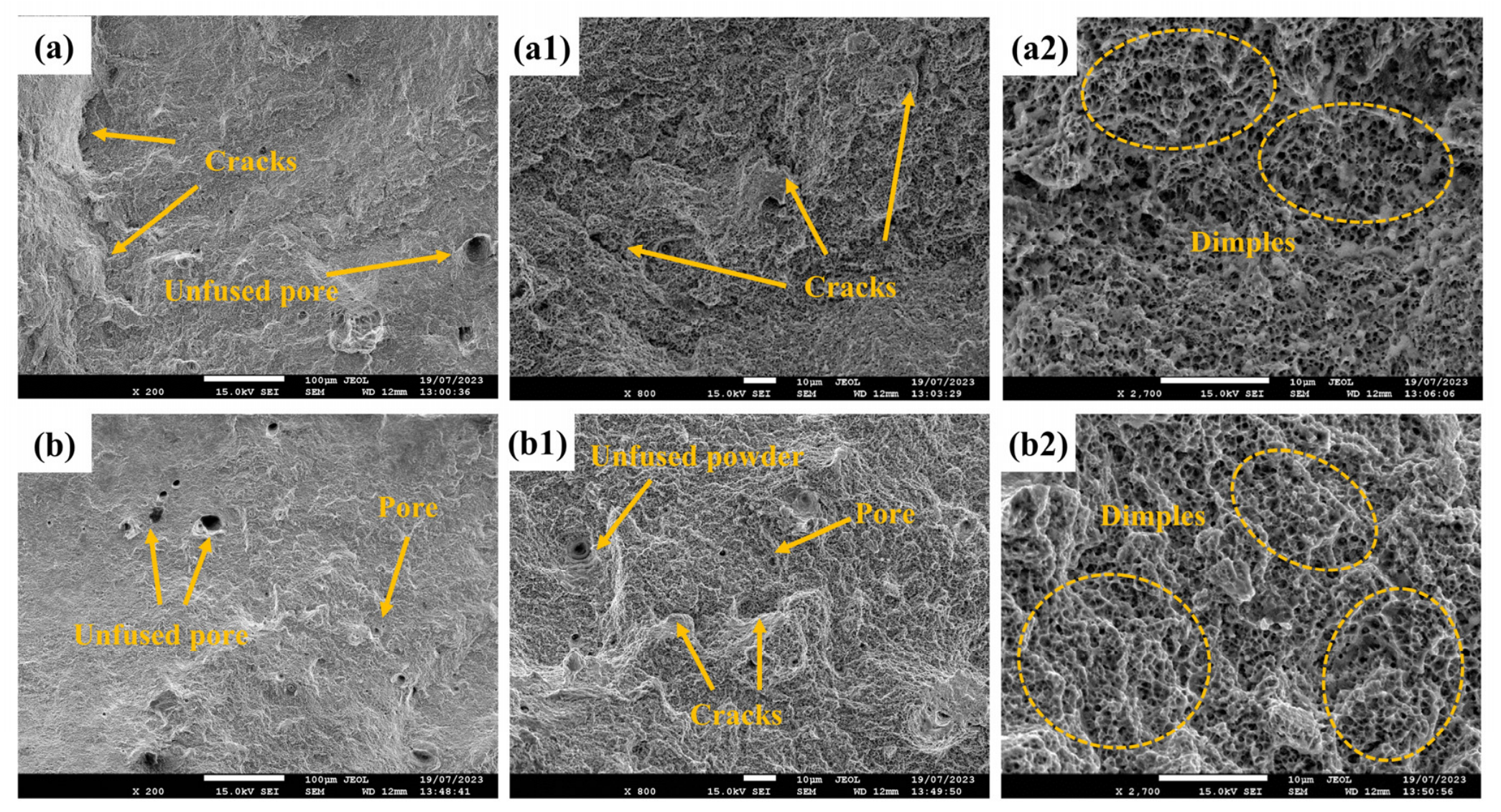
In Figure 12, a nuanced portrayal of the tensile fracture surfaces of the LPBFed and LPBF-UITed samples emerges, revealing intricate details of their structural integrity. Both samples, meticulously scrutinized, unveil a landscape marked by numerous dimples, emblematic of a characteristic ductile fracture mode. Upon closer inspection, the fracture features of the LPBFed sample come into focus, revealing a tapestry of voids, pores, cracks, and dimples. In stark contrast, the fracture surface of the LPBF-UITed sample paints a different picture. While it also showcases metallurgical anomalies such as voids and pores, cracks are noticeably diminished in number and length. This intriguing observation hints at UIT’s adeptness in striking a delicate balance between strength and ductility within the material. A more granular examination in Figure 12(a2,b2) underscores this transformative effect. Here, the tensile fracture surface of the LPBF-UITed sample exhibits larger, deeper, and more uniformly distributed dimples when compared to its LPBFed counterpart. This subtle yet pivotal shift underscores a discernible enhancement in ductility following UIT, illuminating a path toward optimizing material properties with profound implications for the realm of materials science and engineering.

4. Discussion

4.1. Microstructural Evolution

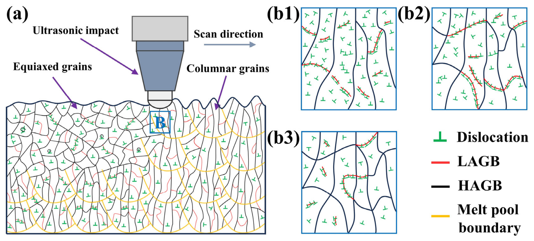
In Figure 13, a visually compelling schematic unfolds, elucidating the intricate microstructural evolution witnessed in the samples before and after UIT. Initially, the LPBFed sample exhibits a distinct microstructure characterized by long columnar grains coupled with a discernible arrangement of fish-scale-shaped melt pools, which can be attributed to the Gaussian energy distribution of the laser beam. Noteworthy clusters of dislocations are concentrated along the boundaries of the melt pools, underscoring the material’s inherent structural intricacies. Following UIT, a gradual yet transformative shift in plastic deformation becomes apparent, particularly evident from the top to the middle layer of the sample. Notably, the surface-level accumulation of melt pools diminishes, giving rise to a metamorphosis in the columnar grains, which morph into irregularly shaped equiaxed grains. Concurrent with this microstructural transformation, enhanced dislocation-related plastic deformation is inferred from the gradient distribution of KAM and the increased LAGB fraction. Delving deeper into the microstructural evolution within the surface layer during the UIT process, a captivating narrative unfolds, as depicted in Figure 13(b1–b3). The severe plastic deformation induced by UIT promotes dislocation accumulation and rearrangement, which may facilitate the development of dislocation-related substructures and LAGBs. These dislocation walls gradually mature into LAGBs through subsequent dislocation movements and rearrangements. Crucially, LAGBs serve as dynamic crucibles where dislocations are absorbed, leading to a transformative journey toward High-Angle Grain Boundaries (HAGBs). This evolution translates into augmented grain boundary angles, epitomizing a process where coarse grains are meticulously subdivided into finer counterparts [26,41,42]. However, at the deposition layer’s base within the LPBF-UITed sample, the influence of UIT is inherently limited. Consequently, the intensity of dislocation accumulation and plastic deformation gradually decreases with increasing depth, accompanied by a progressive decrease in the LAGB fraction. This evolution reflects the depth-dependent response of the microstructure to UIT, which is governed by both the attenuation of the applied plastic deformation and the intrinsic microstructural characteristics of the material.

4.2. Strengthening Mechanisms

As is well-known, factors affecting the tensile properties of additively manufactured specimens include metallurgical defects [43], residual stress state [44], and microstructure [45]. Since no changes in metallurgical defects of the specimens before and after UIT were observed in this study, it is considered that the ultrasonic shockwaves did not alter the metallurgical defects in the specimens. This study’s findings indicate that UIT converts the specimen’s surface residual tensile stresses into compressive stresses and induces severe plastic deformation in the near-surface region, accompanied by grain subdivision, increased LAGB fraction, and enhanced local lattice misorientation. Therefore, the improvement in the tensile properties of LPBF-UITed specimens can be attributed to the following strengthening mechanisms.
The strength of the specimens is closely related to the grain size. As described in Section 3.4, after the application of UIT, the dislocation density and LAGB increase in the specimen, and sub-boundaries subdivide columnar grains into smaller equiaxed grains. Therefore, LPBF-UITed specimens have more grain boundaries. According to the Hall–Petch strengthening theory, grain boundary strengthening can be expressed as follows [46]:
Δ σ H P = σ 0 + k d 1 / 2
where σ0 is the frictional stress, k is a constant, and d is the grain diameter. Since grain boundaries can act as obstacles that impede the initiation and propagation of dislocations, an increase in the number of grain boundaries leads to increased resistance to dislocation slip and, consequently, an improvement in the strength of the specimen [47].
The increase in specimen strength can be attributed to grain refinement and strain hardening associated with the enhanced dislocation-related plastic deformation induced by UIT. The increased LAGB fraction and KAM values provide indirect evidence supporting the contribution of dislocation-related strengthening. The increase in dislocation density due to UIT and its gradient distribution contributes to strain hardening. According to the Taylor formula, dislocation strengthening can be expressed as [48]:
Δ σ d = α M G m b ρ
where α is a constant reflecting the strength of dislocation interaction, M is the Taylor factor, Gm is the shear modulus, b represents the Burgers vector, and ρ stands for dislocation density. When the specimen is subjected to tensile loads, the interaction between dislocations inhibits dislocation motion, thereby increasing the strength of the specimen.
In addition, the residual stress state of the specimen also has a significant impact on its tensile performance. The surface of the LPBFed specimen forms residual tensile stresses due to thermal effects, which accelerate the crack propagation rate under tensile loads, thus negatively affecting the tensile performance of the specimen. Under the action of UIT, the surface of the LPBF-UITed specimen undergoes severe plastic deformation, transforming the surface’s tensile stress state into a compressive stress state. The residual compressive stress generated by UIT can reduce the effective tensile stress acting on the near-surface region during mechanical loading, which may contribute to the enhanced tensile strength and ductility observed in this study [49,50].
In summary, the strengthening mechanism of UIT combines Hall–Petch, dislocation, and residual compressive stress strengthening. In this study, the hardening effect caused by dislocation strengthening also led to the deterioration of the ductility [51,52]. However, the surface grain refinement of the LPBF-UITed specimen, while maintaining a coarse-grain structure at the bottom, effectively enhances coordinated deformation between grains, thereby improving the ductility of the specimen [53]. Additionally, the inhibitory effect of residual compressive stress on crack initiation and propagation also enhances the ductility of the specimen. Due to the combined improvements in gradient grain structure and residual compressive stress, which outweigh the detrimental effects of dislocation strengthening, UIT enhances the elongation of the specimen.
Despite these advantages, UIT still faces challenges in treating complex LPBF components. Intricate geometries, narrow features, and internal channels may restrict tool accessibility and lead to non-uniform treatment. In addition, large-area processing may require multi-axis or robotic systems, increasing processing time and cost. Therefore, further studies are needed to evaluate the scalability and industrial applicability of UIT for complex LPBF components. Therefore, UIT is currently more readily applicable to externally accessible surfaces than to enclosed or highly confined internal features.

5. Conclusions

In this study, the impact of UIT on the surface morphology, residual stress distribution, microstructural evolution, and mechanical properties of LPBFed 316L stainless steel specimens were meticulously examined. The findings distilled from this research are summarized as follows:
(1)
UIT played a pivotal role in enhancing the surface morphology of LPBFed specimens, leading to a discernible reduction in surface roughness. Notably, the primary phase of the specimens remained unchanged post UIT. However, there was a notable shift in diffraction peaks towards higher angles and a decrease in peak intensity.
(2)
UIT instigated a remarkable transformation in the surface microstructure of LPBFed specimens. The columnar grains, characterized by epitaxial growth on the surface, underwent a profound alteration, transitioning into irregularly shaped equiaxed grains. This transformation facilitated a reduction in grain size, an augmentation in the proportion of Low-Angle Grain Boundaries (LAGBs), and a substantial increase in dislocation density. This evolution was attributed to the severe plastic deformation induced by ultrasonic impact, promoting dislocation proliferation and motion within the material’s surface layer. Consequently, coarse columnar grains were meticulously subdivided into smaller equiaxed grains through the evolution of dislocations into subgrain boundaries.
(3)
UIT exerted a profound impact on the residual stress distribution within the LPBFed specimens. The original residual tensile stresses present at the surface were effectively transformed into compressive stresses, reaching depths of approximately 450 μm. Concurrently, UIT substantially augmented both the surface and depth-direction microhardness of the LPBFed specimens. Surface microhardness witnessed an impressive increase of approximately 17.64%, with the hardened layer extending to a depth of about 500 μm.
(4)
UIT emerged as a potent tool in enhancing the tensile performance of the specimens. Ultimate tensile strength, yield strength, and elongation experienced significant improvements of 14.5%, 15.2%, and 18.0%, respectively. These enhancements were underpinned by a synergistic interplay of strengthening mechanisms, encompassing Hall–Petch, dislocation, and residual stress strengthening. Moreover, the augmented plasticity observed in the specimens was attributed to the gradient grain structure and residual stress, marking a remarkable advancement in the material’s mechanical properties.
In essence, this study sheds light on the multifaceted influence of UIT on LPBFed 316L stainless steel specimens, unraveling a tapestry of microstructural intricacies and mechanical enhancements. These findings contribute to our fundamental understanding of the intricate interplay between external treatments and material behavior and pave the way for innovative applications in the realm of advanced materials and manufacturing.

Author Contributions

Conceptualization, Q.B. and X.M.; methodology, Q.B. and P.H.; validation, J.Z.; formal analysis, Q.B. and M.T.; investigation, P.H. and J.Z.; resources, X.M.; data curation, P.H.; writing—original draft preparation, Q.B. and M.T.; writing—review and editing, Q.B., P.H. and X.M.; visualization, M.T.; supervision, X.M.; project administration, Q.B. and X.M. All authors have read and agreed to the published version of the manuscript.

Funding

This research was funded by the China Postdoctoral Science Foundation, grant number 2025M770893.

Data Availability Statement

The data presented in this study are available from the corresponding author upon reasonable request.

Conflicts of Interest

The authors declare no conflict of interest.

References

  1. Li, X.; Willy, H.J.; Chang, S.; Lu, W.; Herng, T.S.; Ding, J. Selective laser melting of stainless steel and alumina composite: Experimental and simulation studies on processing parameters, microstructure and mechanical properties. Mater. Des. 2018, 145, 1–10. [Google Scholar] [CrossRef] [Scilit]
  2. Al-Rashidy, Z.M.; Farag, M.M.; Abdel Ghany, N.A.; Ibrahim, A.M.; Abdel-Fattah, W.I. Orthopaedic bioactive glass/chitosan composites coated 316L stainless steel by green electrophoretic co-deposition. Surf. Coat. Technol. 2018, 334, 479–490. [Google Scholar] [CrossRef] [Scilit]
  3. Biehler, J.; Hoche, H.; Oechsner, M. Corrosion properties of polished and shot-peened austenitic stainless steel 304L and 316L with and without plasma nitriding. Surf. Coat. Technol. 2017, 313, 40–46. [Google Scholar] [CrossRef] [Scilit]
  4. Herzog, D.; Seyda, V.; Wycisk, E.; Emmelmann, C. Additive manufacturing of metals. Acta Mater. 2016, 117, 371–392. [Google Scholar] [CrossRef] [Scilit]
  5. Suryawanshi, J.; Prashanth, K.G.; Ramamurty, U. Mechanical behavior of selective laser melted 316L stainless steel. Mater. Sci. Eng. A 2017, 696, 113–121. [Google Scholar] [CrossRef] [Scilit]
  6. Casati, R.; Lemke, J.; Vedani, M. Microstructure and Fracture Behavior of 316L Austenitic Stainless Steel Produced by Selective Laser Melting. J. Mater. Sci. Technol. 2016, 32, 738–744. [Google Scholar] [CrossRef] [Scilit]
  7. Leicht, A.; Yu, C.H.; Luzin, V.; Klement, U.; Hryha, E. Effect of scan rotation on the microstructure development and mechanical properties of 316L parts produced by laser powder bed fusion. Mater. Charact. 2020, 163, 110309. [Google Scholar] [CrossRef] [Scilit]
  8. Kalentics, N.; de Seijas, M.O.V.; Griffiths, S.; Leinenbach, C.; Logé, R.E. 3D laser shock peening—A new method for improving fatigue properties of selective laser melted parts. Addit. Manuf. 2020, 33, 101112. [Google Scholar] [CrossRef] [Scilit]
  9. Tian, C.; Li, X.; Li, H.; Guo, G.; Wang, L.; Rong, Y. The effect of porosity on the mechanical property of metal-bonded diamond grinding wheel fabricated by selective laser melting (SLM). Mater. Sci. Eng. A 2019, 743, 697–706. [Google Scholar] [CrossRef] [Scilit]
  10. Galy, C.; Le Guen, E.; Lacoste, E.; Arvieu, C. Main defects observed in aluminum alloy parts produced by SLM: From causes to consequences. Addit. Manuf. 2018, 22, 165–175. [Google Scholar] [CrossRef] [Scilit]
  11. Gao, C.; Chen, X.; Su, C.; Chen, X. Location dependence of microstructure and mechanical properties on wire arc additively manufactured nuclear grade steel. Vacuum 2019, 168, 108818. [Google Scholar] [CrossRef] [Scilit]
  12. Thijs, L.; Montero Sistiaga, M.L.; Wauthle, R.; Xie, Q.; Kruth, J.-P.; Van Humbeeck, J. Strong morphological and crystallographic texture and resulting yield strength anisotropy in selective laser melted tantalum. Acta Mater. 2013, 61, 4657–4668. [Google Scholar] [CrossRef] [Scilit]
  13. Xu, M.; Guo, H.; Wang, Y.; Hou, Y.; Dong, Z.; Zhang, L. Mechanical properties and microstructural characteristics of 316L stainless steel fabricated by laser powder bed fusion and binder jetting. J. Mater. Res. Technol. 2023, 24, 4427–4439. [Google Scholar] [CrossRef] [Scilit]
  14. Fang, Z.; Lu, L.; Chen, L.; Guan, Y. Laser Polishing of Additive Manufactured Superalloy. Procedia CIRP 2018, 71, 150–154. [Google Scholar] [CrossRef] [Scilit]
  15. Qiu, C.; Adkins, N.J.E.; Attallah, M.M. Microstructure and tensile properties of selectively laser-melted and of HIPed laser-melted Ti–6Al–4V. Mater. Sci. Eng. A 2013, 578, 230–239. [Google Scholar] [CrossRef] [Scilit]
  16. Malakizadi, A.; Mallipeddi, D.; Dadbakhsh, S.; M’Saoubi, R.; Krajnik, P. Post-processing of additively manufactured metallic alloys—A review. Int. J. Mach. Tools Manuf. 2022, 179, 103908. [Google Scholar] [CrossRef] [Scilit]
  17. Kasperovich, G.; Hausmann, J. Improvement of fatigue resistance and ductility of TiAl6V4 processed by selective laser melting. J. Mater. Process. Technol. 2015, 220, 202–214. [Google Scholar] [CrossRef] [Scilit]
  18. Chen, L.; Richter, B.; Zhang, X.; Bertsch, K.B.; Thoma, D.J.; Pfefferkorn, F.E. Effect of laser polishing on the microstructure and mechanical properties of stainless steel 316L fabricated by laser powder bed fusion. Mater. Sci. Eng. A 2021, 802, 140579. [Google Scholar] [CrossRef] [Scilit]
  19. Liu, J.; Zhao, Z.; Rao, D.; Yang, Y.; Zheng, L.; Wang, C.; Deng, P.; Niu, L.; Huang, Z. Synergistic enhancement of mechanical and tribological properties in WC-reinforced 316L stainless steel matrix composite fabricated by laser powder bed fusion. J. Mater. Res. Technol. 2025, 37, 617–628. [Google Scholar] [CrossRef] [Scilit]
  20. Duarte, V.R.; Rodrigues, T.A.; Schell, N.; Miranda, R.M.; Oliveira, J.P.; Santos, T.G. Hot forging wire and arc additive manufacturing (HF-WAAM). Addit. Manuf. 2020, 35, 101193. [Google Scholar] [CrossRef] [Scilit]
  21. Tong, Z.; Liu, H.; Jiao, J.; Zhou, W.; Yang, Y.; Ren, X. Improving the strength and ductility of laser directed energy deposited CrMnFeCoNi high-entropy alloy by laser shock peening. Addit. Manuf. 2020, 35, 101417. [Google Scholar] [CrossRef] [Scilit]
  22. Sugavaneswaran, M.; Jebaraj, A.V.; Kumar, M.D.B.; Lokesh, K.; Rajan, A.J. Enhancement of surface characteristics of direct metal laser sintered stainless steel 316L by shot peening. Surf. Interfaces 2018, 12, 31–40. [Google Scholar] [CrossRef] [Scilit]
  23. Mordyuk, B.N.; Prokopenko, G.I. Ultrasonic impact peening for the surface properties’ management. J. Sound Vib. 2007, 308, 855–866. [Google Scholar] [CrossRef] [Scilit]
  24. Lv, J.; Alexandrov, I.V.; Luo, K.; Lu, H.; Lu, J. Microstructural evolution and anisotropic regulation in tensile property of cold metal transfer additive manufactured Ti6Al4V alloys via ultrasonic impact treatment. Mater. Sci. Eng. A 2022, 859, 144177. [Google Scholar] [CrossRef] [Scilit]
  25. Zhang, M.; Liu, C.; Shi, X.; Chen, X.; Chen, C.; Zuo, J.; Lu, J.; Ma, S. Residual Stress, Defects and Grain Morphology of Ti-6Al-4V Alloy Produced by Ultrasonic Impact Treatment Assisted Selective Laser Melting. Appl. Sci. 2016, 6, 304. [Google Scholar] [CrossRef] [Scilit]
  26. Diao, M.; Guo, C.; Sun, Q.; Jiang, F.; Li, L.; Li, J.; Xu, D.; Liu, C.; Song, H. Improving mechanical properties of austenitic stainless steel by the grain refinement in wire and arc additive manufacturing assisted with ultrasonic impact treatment. Mater. Sci. Eng. A 2022, 857, 144044. [Google Scholar] [CrossRef] [Scilit]
  27. Cui, Z.; Mi, Y.; Qiu, D.; Dong, P.; Qin, Z.; Gong, D.; Li, W. Microstructure and mechanical properties of additively manufactured CrMnFeCoNi high-entropy alloys after ultrasonic surface rolling process. J. Alloys Compd. 2021, 887, 161393. [Google Scholar] [CrossRef] [Scilit]
  28. Xu, Q.; Yang, X.; Liu, J.; Qiu, Z.; Li, G. Reconstruction mechanism of surface integrity for laser additive manufactured 316 L stainless steel subjected to ultrasonic surface rolling process: Numerical simulation and experimental verification. Met. Mater. Int. 2024, 30, 2745–2756. [Google Scholar] [CrossRef] [Scilit]
  29. Maleki, E.; Unal, O.; Doubrava, M.; Pantelejev, L.; Bagherifard, S.; Guagliano, M. Application of impact-based and laser-based surface severe plastic deformation methods on additively manufactured 316L: Microstructure, tensile and fatigue behaviors. Mater. Sci. Eng. A 2024, 916, 147360. [Google Scholar] [CrossRef] [Scilit]
  30. Wang, Z.; Chen, M.; Jia, Z.; Li, R.; Sun, Z.; Sun, G. Tailoring the mechanical and corrosion properties of direct metal deposited 316L stainless steel by underwater ultrasonic impact treatment. Mater. Sci. Eng. A 2025, 924, 147844. [Google Scholar] [CrossRef] [Scilit]
  31. Chen, H.; Zhang, Z.; Zhang, J.; Ji, H.; Meng, Z.; Zhang, H.; Meng, X. Effect of Ultrasonic Impact Strengthening on Surface Properties of 316L Stainless Steel Prepared by Laser Selective Melting. Coatings 2022, 12, 1243. [Google Scholar] [CrossRef] [Scilit]
  32. Zhang, B.; Li, Y.; Bai, Q. Defect Formation Mechanisms in Selective Laser Melting: A Review. Chin. J. Mech. Eng. 2017, 30, 515–527, Erratum in Chin. J. Mech. Eng. 2017, 30, 1476. [Google Scholar] [CrossRef] [Scilit]
  33. Zhou, J.; Zhou, X.; Li, H.; Hu, J.; Han, X.; Liu, S. In-situ laser shock peening for improved surface quality and mechanical properties of laser-directed energy-deposited AlSi10Mg alloy. Addit. Manuf. 2022, 60, 103177. [Google Scholar] [CrossRef] [Scilit]
  34. Fang, Z.-C.; Wu, Z.-L.; Huang, C.-G.; Wu, C.-W. Review on residual stress in selective laser melting additive manufacturing of alloy parts. Opt. Laser Technol. 2020, 129, 106283. [Google Scholar] [CrossRef] [Scilit]
  35. Yakout, M.; Elbestawi, M.A.; Veldhuis, S.C. A study of the relationship between thermal expansion and residual stresses in selective laser melting of Ti-6Al-4V. J. Manuf. Process. 2020, 52, 181–192. [Google Scholar] [CrossRef] [Scilit]
  36. Kreitcberg, A.; Brailovski, V.; Turenne, S. Effect of heat treatment and hot isostatic pressing on the microstructure and mechanical properties of Inconel 625 alloy processed by laser powder bed fusion. Mater. Sci. Eng. A 2017, 689, 1–10. [Google Scholar] [CrossRef] [Scilit]
  37. Li, S.; Wei, Q.; Shi, Y.; Zhu, Z.; Zhang, D. Microstructure Characteristics of Inconel 625 Superalloy Manufactured by Selective Laser Melting. J. Mater. Sci. Technol. 2015, 31, 946–952, Corrigendum in J. Mater. Sci. Technol. 2016, 32, e1. [Google Scholar] [CrossRef] [Scilit]
  38. Kalentics, N.; Huang, K.; Ortega Varela de Seijas, M.; Burn, A.; Romano, V.; Logé, R.E. Laser shock peening: A promising tool for tailoring metallic microstructures in selective laser melting. J. Mater. Process. Technol. 2019, 266, 612–618. [Google Scholar] [CrossRef] [Scilit]
  39. Sadhu, A.; Sarkar, S.; Chattopadhyay, A.; Mypati, O.; Pal, S.K.; Nath, A.K. Effect of Laser Shock Peening on micro-structure and mechanical properties of Friction Stir Welded CuCrZr sheets. Mater. Sci. Eng. A 2022, 831, 142238. [Google Scholar] [CrossRef] [Scilit]
  40. Wang, J.; Xue, Y.; Xu, D.; Zeng, Y.; Li, L.; Wang, Z.; Jiang, F. Effects of layer-by-layer ultrasonic impact treatment on microstructure and mechanical properties of 304 stainless steel manufactured by directed energy deposition. Addit. Manuf. 2023, 68, 103523. [Google Scholar] [CrossRef] [Scilit]
  41. Zhao, X.; Ren, B.; Zhang, Y.; Wang, H.; Liu, Y.; Zhang, X.; Chen, C. Microstructural evolution and strengthening mechanisms of CMT directed energy deposition-arc with interlayer ultrasonic impact treatment manufactured AZ31 magnesium alloy. Mater. Sci. Eng. A 2023, 879, 145267. [Google Scholar] [CrossRef] [Scilit]
  42. Wang, Z.D.; Sun, G.F.; Lu, Y.; Chen, M.Z.; Bi, K.D.; Ni, Z.H. Microstructural characterization and mechanical behavior of ultrasonic impact peened and laser shock peened AISI 316L stainless steel. Surf. Coat. Technol. 2020, 385, 125403. [Google Scholar] [CrossRef] [Scilit]
  43. Wang, Z.; Yang, S.; Peng, Z.; Gao, Z. Effect of defects in laser selective melting of Ti-6Al-4V alloy on microstructure and mechanical properties after heat treatment. Opt. Laser Technol. 2022, 156, 108522. [Google Scholar] [CrossRef] [Scilit]
  44. Song, B.; Dong, S.; Liu, Q.; Liao, H.; Coddet, C. Vacuum heat treatment of iron parts produced by selective laser melting: Microstructure, residual stress and tensile behavior. Mater. Des. (1980–2015) 2014, 54, 727–733, Corrigendum in Mater. Des. (1980–2015) 2020, 186, 108335. [Google Scholar] [CrossRef] [Scilit]
  45. Wu, D.; Yu, C.; Wang, Q.; Niu, F.; Ma, G.; Wang, H.; Zhou, C.; Zhang, B. Synchronous-hammer-forging-assisted laser directed energy deposition additive manufacturing of high-performance 316L samples. J. Mater. Process. Technol. 2022, 307, 117695. [Google Scholar] [CrossRef] [Scilit]
  46. Liu, W.H.; Wu, Y.; He, J.Y.; Nieh, T.G.; Lu, Z.P. Grain growth and the Hall–Petch relationship in a high-entropy FeCrNiCoMn alloy. Scr. Mater. 2013, 68, 526–529. [Google Scholar] [CrossRef] [Scilit]
  47. Cui, C.; Cui, X.; Li, X.; Luo, K.; Lu, J.; Ren, X.; Zhou, J.; Fang, C.; Farkouh, R.; Lu, Y. Plastic-deformation-driven SiC nanoparticle implantation in an Al surface by laser shock wave: Mechanical properties, microstructure characteristics, and synergistic strengthening mechanisms. Int. J. Plast. 2018, 102, 83–100. [Google Scholar] [CrossRef] [Scilit]
  48. Ma, X.; Zha, M.; Wang, S.; Yang, Y.; Jia, H.; Gao, D.; Wang, C.; Wang, H. A rolled Mg−8Al−0.5Zn−0.8Ce alloy with high strength-ductility synergy via engineering high-density low angle boundaries. J. Magnes. Alloys 2022, 10, 2889–2900. [Google Scholar] [CrossRef] [Scilit]
  49. Luo, S.; Zhou, L.; Nie, X.; Li, Y.; He, W. The compound process of laser shock peening and vibratory finishing and its effect on fatigue strength of Ti-3.5Mo-6.5Al-1.5Zr-0.25Si titanium alloy. J. Alloys Compd. 2019, 783, 828–835. [Google Scholar] [CrossRef] [Scilit]
  50. Leuders, S.; Thöne, M.; Riemer, A.; Niendorf, T.; Tröster, T.; Richard, H.A.; Maier, H.J. On the mechanical behaviour of titanium alloy TiAl6V4 manufactured by selective laser melting: Fatigue resistance and crack growth performance. Int. J. Fatigue 2013, 48, 300–307. [Google Scholar] [CrossRef] [Scilit]
  51. Li, Y.; Lu, Z.; Li, T.; Li, D.; Lu, J.; Liaw, P.K.; Zou, Y. Effects of Surface Severe Plastic Deformation on the Mechanical Behavior of 304 Stainless Steel. Metals 2020, 10, 831. [Google Scholar] [CrossRef] [Scilit]
  52. Yang, X.; Wang, X.; Ling, X.; Wang, D. Enhanced mechanical behaviors of gradient nano-grained austenite stainless steel by means of ultrasonic impact treatment. Results Phys. 2017, 7, 1412–1421. [Google Scholar] [CrossRef] [Scilit]
  53. Sun, Y.T.; Kong, X.; Wang, Z.B. Superior mechanical properties and deformation mechanisms of a 304 stainless steel plate with gradient nanostructure. Int. J. Plast. 2022, 155, 103336. [Google Scholar] [CrossRef] [Scilit]
Figure 1. 316L stainless steel powder: (a) SEM morphology; (b) particle size distribution.
Coatings 16 01101 g001
Figure 2. (a) Schematic diagram of LPBF. (b) Schematic diagram of the scanning strategy. (c) Dimensions of tensile specimens. (d) Schematic diagram of the ultrasonic impact device. (e) Block sample processing area. (f) Tensile specimen processing area.
Coatings 16 01101 g002
Figure 3. (a) The three-dimensional surface morphology of the LPBFed sample. (b) The three-dimensional surface morphology of the LPBF-UITed sample. (c) 2D profiles of all samples. (d) Average of Ra and Sa.
Coatings 16 01101 g003
Figure 4. (a) XRD patterns of LPBFed and LPBF-UITed samples. (b) Partial enlarged image of XRD pattern.
Coatings 16 01101 g004
Figure 5. Residual stress of LPBFed and LPBF-UITed samples: (a) surface; (b) along the depth direction.
Coatings 16 01101 g005
Figure 6. SEM images of the cross-sectional microstructure of the LPBFed sample: (a) Low-magnification images. (b) Enlarged view of the overlapping area of the molten pool. (c,d) Enlarged views of C and D in (b), respectively.
Coatings 16 01101 g006
Figure 7. SEM images of the cross-sectional microstructure of the LPBF-UITed sample: (a) Low-magnification images. (b) Enlarged view of B in (a). (c,d) Enlarged views of C and D in (b), respectively.
Coatings 16 01101 g007
Figure 8. LPBFed and LPBF-UITed samples: (a,d) EBSD-IPF. (b,e) Grain size distribution map. (c,f) Distribution map of orientation difference angle.
Coatings 16 01101 g008
Figure 9. LPBFed and LPBF-UITed samples: (a,c) KAM map. (b,d) KAM distribution map.
Coatings 16 01101 g009
Figure 10. Microhardness of LPBFed and LPBF-UITed samples: (a) surface; (b) along the depth direction.
Coatings 16 01101 g010
Figure 11. LPBFed and LPBF-UITed samples: (a) stress–strain curves; (b) comparisons of UTS, YS and EL.
Coatings 16 01101 g011
Figure 12. Tensile fracture morphologies of the samples: (aa2) LPBFed sample at different magnifications; (bb2) LPBF-UITed sample at different magnifications.
Coatings 16 01101 g012
Figure 13. (a) Schematic diagram of microstructure evolution of samples before and after UIT; the blue box B indicates the representative region selected for illustrating the local microstructural evolution; (b1b3) enlarged schematic views of region B showing the microstructural evolution during UIT process.
Coatings 16 01101 g013
Table 1. Chemical composition of the 316L stainless steel powder (mass fraction, %) [27].
MoFeCrNiPSCuCSiNMn
2.2–3balance17–1913–15≤0.025≤0.01≤0.5≤0.03≤0.1≤0.1≤2
Table 2. Process parameters of the sample [27].
Process ParameterValue
Scanning speed (mm/s)1000
Laser power (W)160
Scanning interval (mm)0.07
Layer thickness (µm)30
Disclaimer/Publisher’s Note: The statements, opinions and data contained in all publications are solely those of the individual author(s) and contributor(s) and not of MDPI and/or the editor(s). MDPI and/or the editor(s) disclaim responsibility for any injury to people or property resulting from any ideas, methods, instructions or products referred to in the content.