Review

High-Temperature Piezoelectric Gyroscopes for Harsh Industrial Environments: A Review of Materials, Structural Design, and Circuitry

1
Key Laboratory of Sensors, Beijing Information Science & Technology University, Beijing 100192, China
2
Key Laboratory of Modern Measurement & Control Technology, Ministry of Education, Beijing Information Science & Technology University, Beijing 100192, China
*
Authors to whom correspondence should be addressed.
Coatings 2026, 16(7), 810; https://doi.org/10.3390/coatings16070810
Submission received: 5 May 2026 / Revised: 26 June 2026 / Accepted: 30 June 2026 / Published: 7 July 2026
(This article belongs to the Section Surface Characterization, Deposition and Modification)

Highlights

What are the main findings?
  • Optimized microstructure enhances thermal stability and piezoelectric performance.
  • Resonance mode matching and symmetry design improve bias stability at room temperature, but high-temperature validation remains a critical gap.
  • Self-compensation circuits effectively suppress temperature drift and quadrature error.
  • PZT, LiNbO3, AlN, PMN-PT and KNN offer complementary advantages for high-temperature piezoelectric gyroscopes, with distinct trade-offs between piezoelectric coefficient and Curie temperature.
  • Material aging and system integration remain key challenges for current technologies.
What are the implications of the main findings?
  • Solid-state piezoelectric gyroscopes are promising alternatives in harsh environments.
  • Cross-scale manufacturing and smart sensor fusion will overcome performance bottlenecks.
  • Machine learning and AI-driven approaches (temperature drift compensation, mode matching, sensor fusion) offer adaptive solutions for unpredictable harsh industrial conditions.
  • Oil drilling, geothermal, nuclear and aero-engine applications impose diverse temperature requirements (120–1000+ °C), but no existing prototype has been validated beyond laboratory conditions.
  • This multidisciplinary review guides industrial adoption and future research directions.

Abstract

Severe shocks and vibrations are common in industrial settings (such as oil drilling at 200–300 °C and heavy machinery); high-temperature piezoelectric gyroscopes’ solid-state architecture provides remarkable shock and vibration tolerance as well as great reliability. This review covers the most recent advances in the creation of high-temperature piezoelectric gyroscopes from three angles: materials, structural design, and circuit design. First, it emphasises how optimising microstructures can greatly improve the materials’ temperature stability (e.g., PZT with d33 = 562 pC/N and LiNbO3 with Curie temperature ~1210 °C) and piezoelectric coefficient; second, it examines the structural design of piezoelectric gyroscopes based on MEMS/NEMS technology (such as disc-type, ring-type, and beam-type), showing that optimising resonance frequency matching and modal isolation techniques greatly improves the gyroscope’s zero-bias stability (down to 5°/h) and immunity to interference; and third, it summarises the efficacy of optimisation techniques like temperature self-compensation circuit design and structural symmetry design. According to research, problems like high-temperature material ageing (e.g., degradation above 120 °C for silicon-based devices) and the difficulty of system integration continue to limit current technology; in the future, performance bottlenecks will need to be removed through advancements in cross-scale manufacturing technologies and intelligent sensor fusion design. From a multidisciplinary standpoint, this study offers theoretical references and technical recommendations for the industrial use of high-temperature piezoelectric gyroscopes.

1. Introduction

1.1. Research Background and Motivation

A gyroscope is an inertial sensor capable of detecting angular velocity and serves as a core component in inertial systems. Since the 1920s, gyroscopes have undergone rapid development.
In traditional spinning-mass gyroscopes, when the central rotor is free from external disturbances, its axis of rotation maintains a fixed orientation in inertial space due to the principle of conservation of angular momentum. By ‘remembering’ this spatial orientation, the gyroscope can calculate its own angular velocity [1]. Since 1963, fibre-optic gyroscopes (FOGs) based on the Sagnac effect have been widely used in fields such as inertial navigation, guidance and tracking [2,3] due to their high reliability and long service life, stemming from the absence of rotating parts. In recent years, micro-electro-mechanical systems (MEMS) and micro-optical-electro-mechanical systems (MOEMS) gyroscopes have also developed rapidly, benefiting from advantages such as miniaturisation, low power consumption and high reliability, and have continuously achieved breakthroughs in performance optimisation, structural innovation and manufacturing process upgrades [4]. Consequently, gyroscopes have become ubiquitous in both the military sector and commercial applications across conventional environments such as the automotive, consumer electronics and medical industries. They are frequently employed in tactical navigation and control, precision agriculture, machine control, accident recorders, autonomous vehicles and remote-controlled robots, attitude measurement systems, personal navigation, GPS augmentation and automated food detection [5,6,7].
However, most of the above applications are limited to ambient temperature conditions. As modern industry expands into extreme environments such as deep underground, the deep sea and high-temperature equipment, the demand for gyroscopes in high-temperature environments is becoming increasingly urgent. For example, in oil and gas exploration, Measurement While Drilling (MWD) and Logging While Drilling (LWD) technologies require real-time monitoring of drill string orientation and wellbore trajectory in high-temperature, high-pressure and highly vibrating environments of 200 °C or even over 300 °C downhole [8]. Furthermore, in nuclear power generation, geothermal development, aeroengine monitoring and high-temperature manufacturing processes, gyroscopes are similarly exposed to ambient temperatures exceeding 200 °C [9]. These extreme industrial applications not only demand high measurement accuracy and long-term stability from gyroscopes, but also pose severe challenges to their reliability under extreme temperatures.
In response to the pressing demands of the high-temperature industrial environments described above, piezoelectric gyroscopes, which utilise the piezoelectric effect, offer distinct advantages. Piezoelectric gyroscopes (including quartz tuning fork gyroscopes and piezoelectric MEMS ring gyroscopes) utilise the direct and inverse piezoelectric effects of piezoelectric materials for drive and detection. Their sensitive structures do not require complex electromagnetic coils or optical fibre loops, and they are able to maintain a high mechanical quality factor and frequency stability even at high temperatures [10,11]. Consequently, as the demand for gyroscope performance in extreme environments increases, piezoelectric gyroscopes, with their inherent advantages of simple structure and high-temperature resistance, are expected to become the preferred choice for applications in such environments.

1.2. Comparative Overview of Gyroscope Technologies

The diverse landscape of gyroscope technologies spans nearly a century of development, with each technology occupying a distinct position in the performance-parameter trade space. Understanding these trade-offs is essential for evaluating why piezoelectric gyroscopes are particularly relevant for harsh industrial environments. Table 1 presents a structured comparison of the principal gyroscope families across key performance and operational metrics.
The comparison reveals four distinct technology clusters. Mechanical spinning-mass gyroscopes and ring laser gyroscopes (RLGs) represent the first generation, offering the highest precision (bias stability below 0.01°/h) but at the cost of large size, high power consumption, and limited shock tolerance [5,7]. These systems remain indispensable for strategic-grade navigation but are fundamentally unsuited for deployment in drilling tools, industrial machinery, or compact aeroengine monitoring platforms.
Fibre-optic gyroscopes (FOGs) and their resonant variants (RFOGs) eliminated rotating parts, achieving exceptional reliability and long service life. However, FOGs exhibit significant temperature sensitivity: the thermal expansion of optical fibres induces non-reciprocal phase noise, and the scale factor varies with temperature gradients along the fibre coil [12]. In high-temperature downhole applications, FOG-based inclinometers require bulky vacuum flasks or thermoelectric coolers to maintain internal temperatures below 125 °C, increasing instrument size, cost, and failure risk. Resonant micro-optic gyroscopes (RMOGs), which integrate optical resonators on planar waveguides, offer a miniaturisation pathway but remain constrained by polarisation noise, backscatter, and thermal drift of the resonant cavity [13,14]. The thermal sensitivity of the resonant cavity in RMOGs poses particular challenges for high-temperature operation, as temperature variations alter the refractive index and cavity length, directly affecting the scale factor stability.
Hemispherical resonator gyroscopes (HRGs) occupy a unique position, combining navigation-grade precision (bias stability as low as 0.0056°/h) with exceptional durability and wide temperature tolerance [15]. Micro-scale HRGs fabricated using MEMS processes have demonstrated bias instability of 0.013°/h and have been successfully integrated into rotary inertial navigation systems for autonomous ground vehicles [16]. However, the hemispherical quartz shell requires precision grinding and extensive manual assembly, resulting in prohibitively high costs that limit deployment to aerospace and strategic applications [17].
MEMS gyroscopes represent the most significant advance in miniaturisation and cost reduction. Capacitive MEMS gyroscopes, which dominate consumer and automotive markets, achieve remarkable size and price points but rely on nanometre-scale capacitive gaps that are highly susceptible to particulate contamination, structural damage under shock, and temperature-induced dimensional changes [18]. When exposed to high temperatures, the dielectric properties of silicon and the stability of capacitive electrodes degrade rapidly, limiting reliable operation typically to below 85 °C. Furthermore, although capacitive MEMS gyroscopes offer a wide dynamic range (±250–±2000°/s) at room temperature, this metric is critically dependent on the stability of nanometre-scale capacitive gaps, which deform under thermal and mechanical stress, rendering the stated dynamic range unreliable in harsh industrial environments.
In contrast, piezoelectric MEMS gyroscopes utilise the direct and inverse piezoelectric effects for drive and detection, eliminating the need for sub-micrometre capacitive gaps entirely. The piezoelectric materials employed-such as AlN (Curie temperature >2000 °C, piezoelectric properties maintained up to 1150 °C in argon atmosphere [19]), single-crystal LiNbO3 (Curie temperature ~1210 °C), and engineered PZT ceramics—are intrinsically capable of operation at temperatures far exceeding the limits of silicon-based capacitive devices. The solid-state electrode structure, combined with the high mechanical quality factor of piezoelectric resonators, yields robust vibration immunity and stable performance across wide temperature ranges. These characteristics position piezoelectric MEMS gyroscopes as the most promising solid-state inertial sensing technology for environments characterised by simultaneous high temperature, intense vibration, and mechanical shock—precisely the conditions encountered in oil and gas drilling, geothermal exploration, nuclear facilities, and aeroengine monitoring.
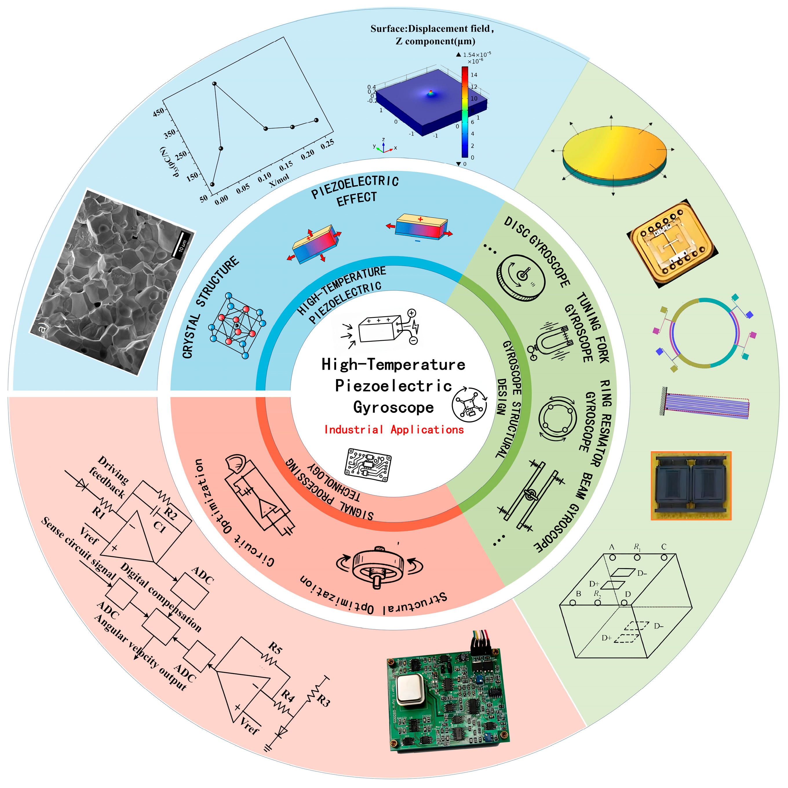
This review paper discusses: (1) the fundamental principles of high-temperature piezoelectric materials and piezoelectric gyroscopes; (2) the current state of development of various types of high-temperature piezoelectric gyroscopes; (3) application scenarios and performance requirements in extreme industrial environments; and (4) technical challenges, optimisation strategies and application potential in high-temperature environments (Figure 1).

1.3. Review Methodology

This review was conducted following a structured literature search and screening protocol to ensure comprehensive and balanced coverage of the field of high-temperature piezoelectric gyroscopes. The methodology comprised three stages: literature search and selection, data extraction, and thematic classification.
Multiple academic databases were systematically searched, including Web of Science, IEEE Xplore, Scopus, and CNKI (China National Knowledge Infrastructure). The search employed combinations of three groups of keywords: (1) gyroscope-related terms, including “gyroscope,” “vibrating gyroscope,” “MEMS gyroscope,” “piezoelectric gyroscope,” and “angular velocity sensor”; (2) piezoelectric material terms, including “piezoelectric material,” “PZT,” “LiNbO3,” “AlN,” “KNN,” and “PMN-PT”; and (3) high-temperature and application terms, including “high temperature,” “harsh environment,” “temperature compensation,” “oil drilling,” “aerospace,” and “nuclear facility.” The primary search focused on articles published from January 2015 to June 2026, supplemented by seminal works predating this window where historically significant (e.g., foundational gyroscope designs from the 1980s–2000s). Both peer-reviewed journal articles and selected high-quality conference proceedings were considered, with the majority of sources published in English. A strictly limited number of authoritative Chinese-language studies were included solely when they provided unique technical contributions unavailable in English literature. Exclusion criteria were applied to remove non-peer-reviewed reports, patents, theses, and conference abstracts lacking full technical content, as well as studies unrelated to high-temperature piezoelectric gyroscopes or those with insufficient detail for meaningful data extraction.
The selected literature was organised into three thematic pillars that form the structural framework of this review: (1) high-temperature piezoelectric materials (Section 3), covering PZT, LiNbO3, AlN, PMN-PT, and KNN-based systems, with a focus on Curie temperature, piezoelectric coefficients, and thermal stability; (2) structural design of piezoelectric gyroscopes (Section 4), including disc-type, tuning-fork, beam-type, ring-type, mass-coupled, and solid-state configurations, with performance metrics such as bias stability, angular random walk, and quality factor; and (3) circuit-level compensation and intelligent optimisation strategies (Section 5 and Section 6), encompassing analogue and digital temperature compensation circuits, structural symmetry design, and emerging machine-learning and artificial-intelligence approaches for temperature drift prediction, mode matching, sensor fusion, and fault diagnosis. This classification reflects the complete technical chain from material foundation to device implementation and system-level optimisation.

2. The Basic Principle of Piezoelectric Gyroscopes

The fundamental working principle of a piezoelectric gyroscope, an angular velocity sensor based on the piezoelectric effect and the Coriolis force, is to detect rotational motion by tracking changes in an oscillating object’s vibration modes.

2.1. Piezoelectric Effect

The asymmetry of the crystal structure is the primary cause of the piezoelectric phenomenon, which was initially noted in natural quartz [20]. The centres of positive and negative charges coincide in a molecule without centre symmetry, but when the spatial arrangement of these charge centres, the crystal structure deviates from the centre of symmetry, an external stress causes polarisation, which transforms mechanical energy into electrical energy. This phenomenon is referred to as the positive piezoelectric effect. On the other hand, piezoelectric crystals experience tiny stretching or compression when subjected to an external electric field; the degree of this deformation remains linear with the strength of the applied electric field. Lattice stretching results from the displacement of internal charges within the crystal when the electric field’s direction coincides with the material’s spontaneous polarisation direction; lattice compression results from an electric field in the opposite direction. This idea allows piezoelectric crystals to directly transform electrical energy into mechanical energy that can be controlled. The mutual link between piezoelectricity and dielectric characteristics is demonstrated by the occurrence of the piezoelectric effect.

2.2. The Operation of a Piezoelectric Gyroscope

The piezoelectric material is the central part of a piezoelectric gyroscope. The piezoelectric material vibrates mechanically in a particular direction when an alternating voltage is supplied to its electrodes based on the piezoelectric effect. The Coriolis force causes the motion of the piezoelectric material to create extra strains when the gyroscope is exposed to an external angular velocity. The piezoelectric material’s upper and lower surfaces become charged as a result of these stresses. Information on the external angular velocity can be collected by gathering the charges produced by the Coriolis force using sensing electrodes on the piezoelectric material, transforming them into voltage signals, and processing them. This is a piezoelectric gyroscope’s fundamental working concept.

3. Recent Advances in the Study of High-Temperature Piezoelectric Materials

3.1. Classification and Properties of High-Temperature Piezoelectric Materials

Piezoelectric materials are widely employed in daily life because of their special capacity to transform electrical energy into mechanical energy and vice versa. They are often found in consumer electronics, healthcare, manufacturing, and the automotive sector. Natural and synthetic materials are the two basic groups into which piezoelectric materials can be divided.
Inorganic minerals like quartz and topaz, as well as some organic and biological materials like wood, bone, and silk, are examples of natural piezoelectric materials. Because inorganic mineral piezoelectric materials do not need complicated synthesis or high-temperature sintering, they significantly lower energy use and pollution. They have outstanding long-term stability because of their chemical inertness, which prevents deterioration. Conversely, organic bio-based piezoelectric materials are very biocompatible and can be inserted into the human body, greatly lowering the possibility of immunological rejection. As a result, natural piezoelectric materials provide invaluable benefits in terms of environmental adaptability and biocompatibility.
Barium titanate (BaTiO3), lead titanate (PbTiO3), lead zirconate titanate (PbZrxTi1−xO3, PZT), lithium niobate (LiNbO3), potassium niobate (KNbO3), and other piezoelectric polycrystals, as well as polymers like polyvinylidene fluoride (PVDF) and composite materials, are examples of artificial piezoelectric materials [21,22]. Lead zirconate titanate (PZT), which has an ABO3 perovskite structure, is the most popular of these in the field of piezoelectric ceramics because of its exceptional stability and piezoelectric and electromechanical qualities. Despite its widespread use in sectors including manufacturing and transportation, it is brittle and hard. Low polarisation efficiency limits the piezoelectric performance of polymer piezoelectric materials, despite their exceptional flexibility and lack of the high-temperature sintering procedures typical of conventional ceramics. Conversely, composite materials combine the flexibility of polymers with the high strength and resilience to high temperatures of ceramics, enabling performance customisation through structural and compositional modifications [23,24,25,26,27].

3.2. Material Performance Evaluation Criteria

3.2.1. Curie Temperature Tc

The Curie temperature is the critical temperature at which a material undergoes a ferroelectric-paraelectric phase transition. When the ambient temperature exceeds the Curie temperature, piezoelectric materials undergo depolarisation due to an increase in their lattice symmetry. Applications of piezoelectric devices require piezoelectric ceramics to have a high Curie temperature, as this ensures stability under normal operating conditions.

3.2.2. Piezoelectric Constant d

The piezoelectric constants represent the charge density generated when mechanical stress is applied or the magnitude of strain produced under an applied electric field; they are key parameters in energy harvesting and actuator applications. Generally speaking, a polarised piezoelectric ceramic possesses only three independent piezoelectric coefficients: d31, d33 and d15. The matrix form of these piezoelectric coefficients is shown in Equation (1), where d33 denotes the magnitude of strain generated in the polarisation direction when a unit-sized electric field, aligned with the sample’s polarisation direction, is applied to the sample. The higher the piezoelectric coefficient of the material, the greater the strain produced under the same voltage drive, and the better the piezoelectric performance [28].
d = 0 0 0 0 d 15 0 0 0 0 d 15 0 0 d 31 d 31 d 33 0 0 0

3.2.3. Dielectric Constant εr

The dielectric constant characterises a material’s ability to become polarised in an electric field; it also describes the response of the material’s electric displacement D to an external electric field E, as shown in Equation (2). The magnitude of ε has a significant influence on the resonant frequency of piezoelectric ceramics; therefore, piezoelectric ceramic materials used in high-frequency applications must have a low ε in order to achieve impedance matching.
ε i j = D i E j

3.2.4. Dielectric Loss tanδ

Dielectric loss refers to the phenomenon whereby, in an alternating electric field, not all electrical energy is converted into mechanical energy; instead, a portion of it is converted into thermal energy. This typically includes polarisation loss, conduction loss and structural loss, among others. Consequently, dielectric loss is a key parameter for assessing the efficiency of energy dissipation in a material under the influence of an electric field.

3.2.5. Mechanical Quality Factor Qm

The mechanical quality factor is a key parameter characterising the energy loss of a material during mechanical vibration; the higher the mechanical quality factor, the lower the energy loss of the piezoelectric material during resonance. It is therefore commonly used to assess the efficiency of piezoelectric materials in resonant applications.

3.2.6. Electromechanical Coupling Coefficient k

The electromechanical coupling coefficient indicates the efficiency of energy conversion between electrical and mechanical energy in piezoelectric materials and is a key parameter in energy harvesting applications.

3.3. Current Status of Research into High-Temperature Piezoelectric Materials

High-temperature piezoelectric materials have been a hot topic of research in the field of materials science and engineering in recent years, primarily targeting core applications such as sensor fabrication and energy harvesting in extreme environments, including aerospace, industrial measurement and control, and energy exploration [29]. In recent years, piezoelectric materials such as lead zirconate titanate (PZT), aluminium nitride (AlN) and lithium niobate (LiNbO3) have frequently been utilised in the MEMS sector. Gyroscopes fabricated from these materials employ a piezoelectric drive and detection mechanism, offering advantages such as a simple structure, high driving force, and strong resistance to interference and shock. The resulting gyroscopes offer high sensitivity, low cost, compact size and low power consumption, making them ideally suited to the demands of applications in extreme environments.
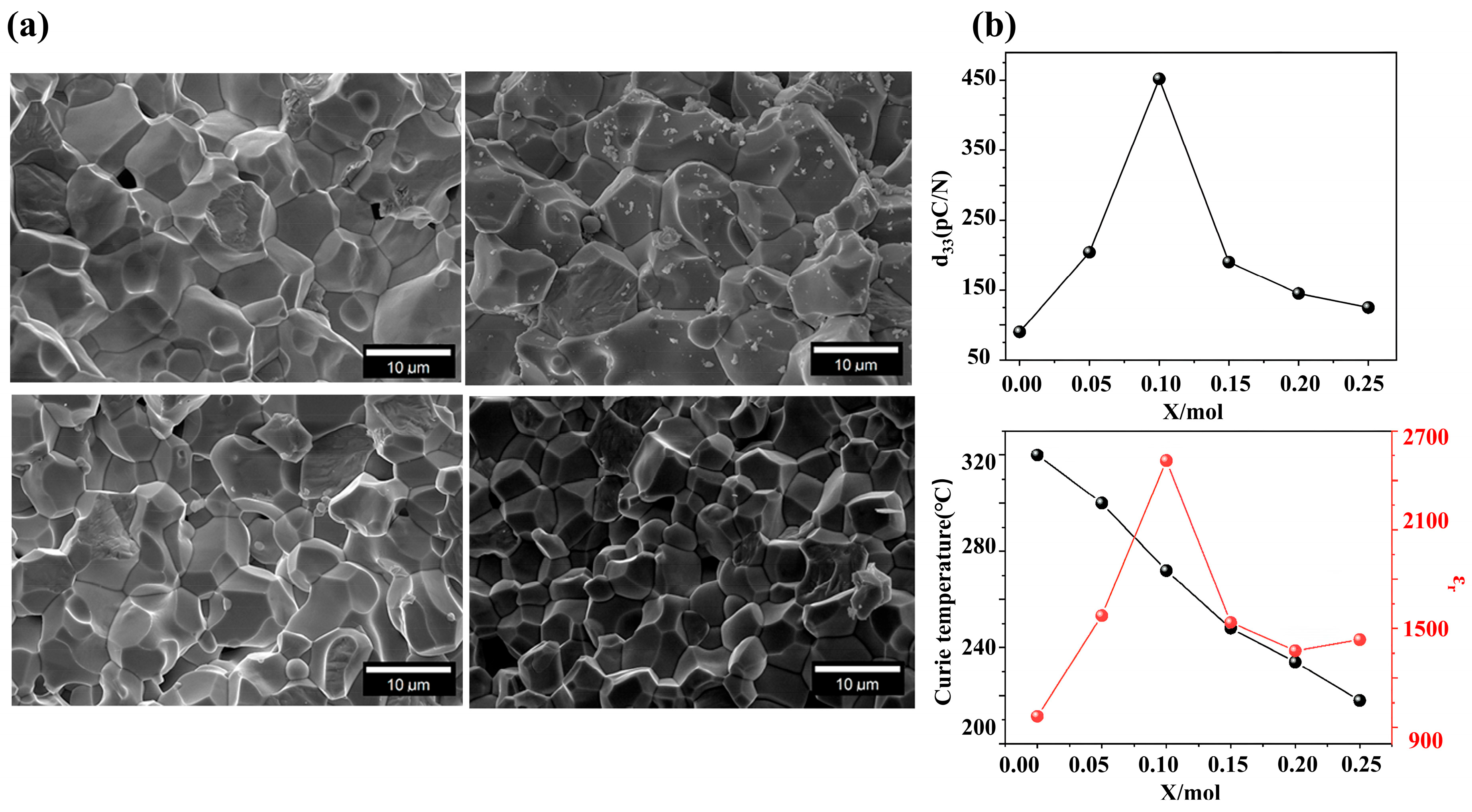
Against this backdrop, Okayasu et al. [30] investigated the power generation characteristics of lead zirconate titanate (E-PZT) piezoelectric ceramics, utilising the inherent direct and inverse piezoelectric effects of PZT to generate electrical signals through the vibration of E-PZT. Although PZT ceramics are piezoelectric materials with a perovskite structure that have been widely used in recent years, as extreme environmental applications place increasingly stringent demands on sensor sensitivity and operating temperature, researchers have made considerable efforts to enhance key performance parameters whilst maintaining the material’s thermal stability [31]. For example, Chen et al. [32] achieved both high piezoelectric performance (d33 = 562 pC/N) and excellent thermal stability (d33 variation within 7% in the range of 20–330 °C) for 0.02Pb(Sb1/2Nb1/2)-0.51PbZrO3-0.47PbTiO3 doped with 0.4 mol% ZnO through high-temperature polarization. Bochenek et al. [33] investigated the effects of mixed doping of rare earth elements such as Sm, Gd, Dy and La with Sb on multicomponent PZT-type ceramics, and under Sm-doped conditions, achieved combined properties of d33 = 341 pC/N and Tc = 321 °C (Figure 2a). Building on this, Zhang et al. [34] went on to develop a 0.10Pb(Yb1/2Nb1/2)O3-0.42PbZrO3-0.48PbTiO3(PYN-PZT) piezoelectric ceramic doped with 1 mol% Nb5+. The Nb5+ doping significantly increased the piezoelectric constant d33, from 437 pC/N to 512 pC/N, whilst maintaining a high Curie temperature of approximately 389 °C. To further enhance the piezoelectric coefficient, Xu et al. [35] optimised the phase structure and electrical properties of the 0.28PIN-0.32PZN-(0.4-x)PT-xPZ multiferroic piezoelectric ceramic by adjusting the Zr/Ti ratio (Figure 2b), achieving a maximum piezoelectric coefficient d33 of 450 pC/N. In addition to conventional doping modification methods, Lee et al. [36] conducted in-depth research into the oriented fabrication process and performance optimisation of PZT-PZNN ceramics. They successfully achieved high orientation of PZT-PZNN ceramics at 950 °C, further increasing the d33 value from 580 pC/N to 920 pC/N.
Lithium niobate (LiNbO3) single crystals represent another important class of high-temperature piezoelectric materials. Compared with traditional PZT ceramics, single-crystal LiNbO3 exhibits a lower piezoelectric coefficient (d33 ≈ 6 pC/N) but possesses a significantly higher Curie temperature (Tc ≈ 1210 °C) and excellent thermal stability, making it inherently suitable for high-temperature applications [37]. Furthermore, as a lead-free piezoelectric material, LiNbO3 has attracted considerable research attention following the implementation of the EU’s RoHS Directive. Owing to its high mechanical quality factor and stable piezoelectric response at elevated temperatures, single-crystal LiNbO3 wafers have been directly employed as the substrate material for piezoelectric disc gyroscopes, where specific Y-cut orientations are selected to optimise the electromechanical coupling for gyroscopic operation [38].
In addition to its direct utilisation as a gyroscope substrate, LiNbO3 has also been introduced as a functional dopant into lead-free ceramic systems to enhance their piezoelectric properties. For example, Feng et al. [39] prepared ternary ceramics (0.73-x)Bi1.05FeO3-xLiNbO3-0.27BaTiO3 using a conventional solid-state sintering method. Near the phase boundary, the piezoelectric constant d33 reached 180 pC/N, and a high Curie temperature (Tc = 535 °C) was still achieved at x = 0.003. It should be noted that such LiNbO3-doped ceramics are distinct from single-crystal LiNbO3 substrates: the former are polycrystalline materials in which LiNbO3 serves as a modifier to tune the phase structure and enhance piezoelectric response, whereas the latter are single-crystal substrates directly employed for gyroscope fabrication.
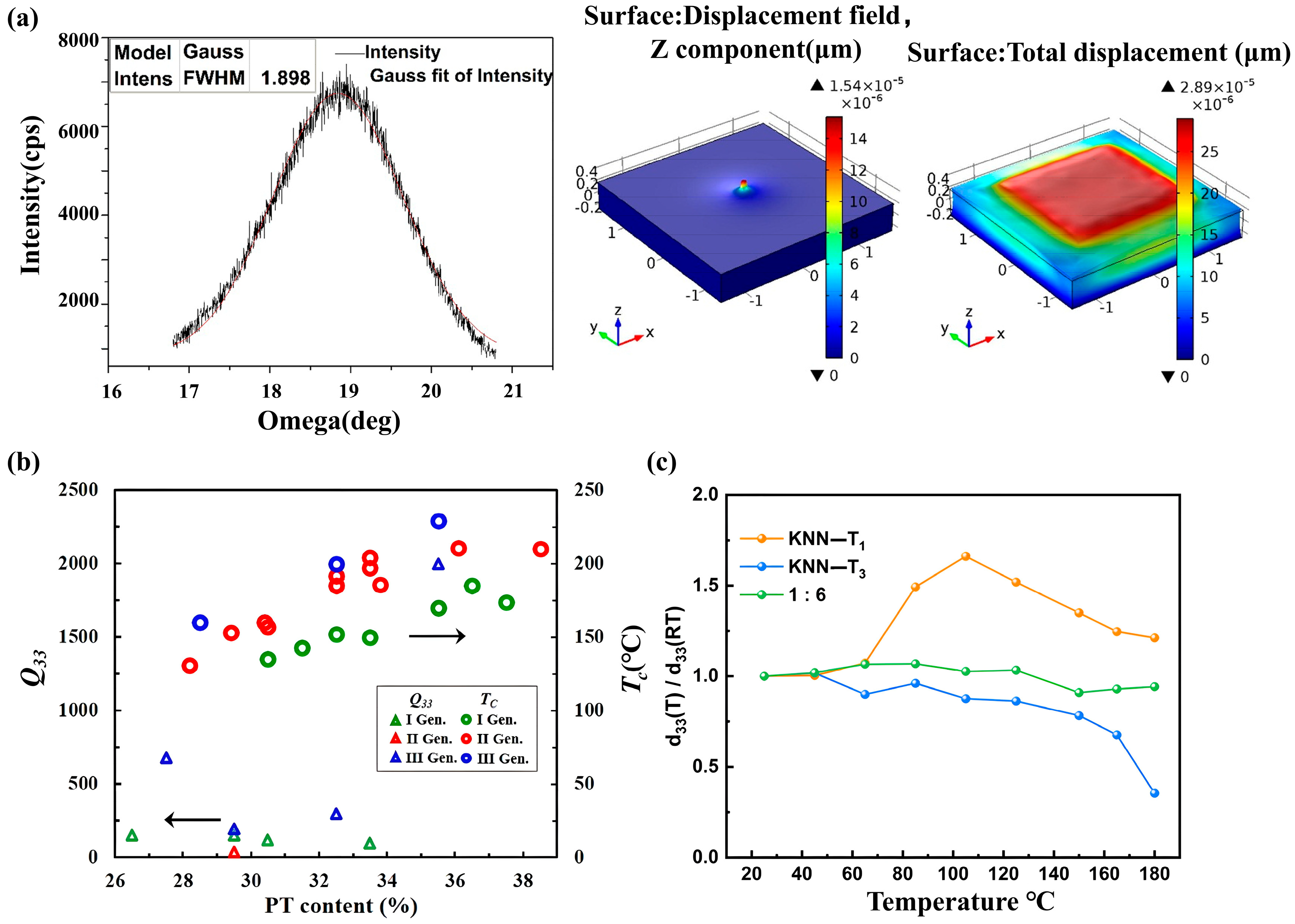
Aluminium nitride is an emerging piezoelectric thin-film material that has emerged in recent years, characterised by a high Curie temperature, low intrinsic loss and stable performance. Its crystal structure is hexagonal wurtzite, exhibiting 6-fold symmetry, which implies that it has ten distinct material constants. These constants manifest differently depending on the crystal orientation; consequently, its piezoelectric properties are primarily dependent on its crystal orientation (Figure 3a) [40]. In 2015, Kim T et al. [41] demonstrated the relationship between the piezoelectric properties of AlN and its crystal orientation by examining the electromechanical coupling coefficients of different resonator modes. Although the piezoelectric coefficients are not as outstanding as those of PZT materials, with appropriate structural design, AlN is expected to meet the drive and sensing requirements of piezoelectric gyroscopes in high-temperature environments. Furthermore, the preparation process for AlN does not involve heavy metals, and its manufacturing process is highly compatible with CMOS technology, with relatively low etching difficulty; consequently, it is frequently selected for the manufacture of MEMS gyroscopes.
In addition to these three mainstream materials, a new generation of piezoelectric materials holds great promise in the fields of high performance and environmental protection, and is therefore attracting considerable attention. Lead magnesium niobate-lead titanate (PMN-PT) is a single-crystal piezoelectric material. Synthetic PMN-PT crystals exhibit very high piezoelectric and mechanical coupling coefficients; however, they have a relatively low Curie temperature range and are relatively expensive. To increase its Curie temperature, starting in 2017, Duran et al. [42,43] used a 5 vol% BT template to texture 0.62[0.75(Pb(Mg1/3Nb2/3)O3)-0.25(Pb(Yb1/2Nb1/2)O3)]-0.38(PbTiO3), resulting in a ceramic with a Curie temperature of 214 °C. Baasandorj et al. [44] provided a systematic review of the latest research progress on relaxor-PT-based ferroelectric crystals (Figure 3b), pointing out that through multi-component design (such as the introduction of PIN, PFN, etc., to form ternary solid solutions) or rare-earth element doping (such as Sm, Eu), the balance between the Curie temperature and piezoelectric properties of PMN-PT-based materials can be regulated to a certain extent. This represents a significant improvement over randomly oriented ceramics; however, given their relatively high cost, the feasibility of large-scale application remains to be seen.
Unmodified potassium-sodium niobate (KNN) piezoelectric ceramics have relatively low piezoelectric constants; however, their piezoelectric properties and Curie temperature can be significantly enhanced through strategies such as optimising the fabrication process or doping modification [45]. Furthermore, KNN materials belong to a lead-free system, containing no toxic elements such as lead or cadmium, and possess good biocompatibility and environmental friendliness. Consequently, they can be safely applied in scenarios with strict requirements for biosafety or environmental protection, such as medical implants and energy harvesting. Cen Z et al. [46] developed a lead-free (1-x)(0.96K0.46Na0.54Nb0.98Ta0.02O3–0.04Bi0.5(Na0.82K0.18)0.5ZrO3)–xCaZrO3((1-x)(0.96KNNT–0.04BNKZ)–xCZ) using a solid-state reaction method. This material exhibits optimal piezoelectric properties (d33 = 300 pC/N) at x = 0.01 and extremely high temperature stability (Te = 200 °C) at x = 0.025. Meanwhile, Lu et al. [47] employed a strategy combining textured thick films with multilayer composite engineering to develop a KNN-based lead-free piezoelectric ceramic with high stability over a wide temperature range (Figure 3c), which exhibits excellent piezoelectric properties (d33 ≈ 467 pC/N) at room temperature and extremely high temperature stability over the range of 25–180 °C (with a change in d33 of only 9.1%).
Figure 3. (a) The rocking curve for (002) orientation of AlN polycrystalline thin films, the simulation results for the sample without a top electrode and the simulation results for the sample with a top electrode. Reprinted with permission from Ref. [40]. Copyright 2015, MDPI AG. (b) Property comparisons between three generation crystals (PMN-PT, PIN-PMN-PT and Mn:PIN-PMN-PT). Reprinted with permission from Ref. [44]. Copyright 2021, MDPI AG. (c) d33 (T)/d33 (RT) of KNN-T1, KNN-T3 and 1:6 ceramics as a function of temperature. Reprinted with permission from Ref. [47]. Copyright 2024, MDPI AG.
Coatings 16 00810 g003
To provide a systematic comparison of the high-temperature piezoelectric materials discussed above, Table 2 summarises their key physical parameters relevant to gyroscope applications, including Curie temperature, piezoelectric coefficient, dielectric properties, mechanical quality factor, and CMOS compatibility.
It is important to emphasise that while high piezoelectric coefficients (d33) are frequently cited as a figure of merit for actuator and energy-harvesting applications, the performance of resonant gyroscopes depends on a more complex interplay of material parameters. The mechanical quality factor (Qm) directly determines energy dissipation in the resonant structure and hence fundamentally limits the bias stability and angular random walk (ARW). The temperature coefficients of elastic constants dictate how resonant frequencies drift under thermal gradients, which in turn degrades scale-factor stability and complicates mode matching. Dielectric loss (tanδ) introduces electrical dissipation and parasitic damping, effectively lowering the apparent Q factor and increasing the noise floor. Electrode stability and thermal-expansion mismatch between the piezoelectric layer and the supporting substrate govern interfacial reliability and long-term drift under cyclic thermal stress. Finally, hermetic packaging and oxidation-resistant electrode metallisation are critical for preventing depoling and maintaining stable performance over the device lifetime in harsh industrial environments [48,49]. Consequently, material selection for high-temperature piezoelectric gyroscopes must optimise these parameters collectively rather than maximising d33 alone.
This comparison highlights the distinct trade-offs among material classes: PZT ceramics offer the highest piezoelectric coefficients but moderate Curie temperatures; LiNbO3 single crystals excel in thermal stability and mechanical quality factor; AlN thin films provide CMOS compatibility and ultra-high-temperature capability; and KNN-based ceramics present lead-free alternatives with improving performance. The selection of a specific material for gyroscope fabrication must therefore balance these parameters against the target operating temperature and application requirements.

4. Research and Developments in Piezoelectric Gyroscopes

4.1. Key Performance Indicators of Gyroscopes

4.1.1. Zero-Bias Stability BI

In the absence of angular velocity input, the output signal from a gyroscope will drift slowly over time; consequently, zero-bias stability is commonly used to characterise the long-term accuracy of a gyroscope.

4.1.2. Angular Random Walk ARW

Internal noise in a gyroscope can cause random fluctuations in angular velocity, which generally manifest as short-term random errors in the output signal; ARW is therefore used to characterise the gyroscope’s accuracy over short periods of time.

4.1.3. Scale Factor SF

The scaling factor, also known as the scale factor, represents the proportional relationship between the gyroscope’s output signal and the actual input angular velocity.

4.1.4. Dynamic Measurement Range

The maximum and minimum angular velocity ranges that a gyroscope is capable of measuring. Generally speaking, a gyroscope with an appropriate dynamic measurement range is selected, as, in theory, better angular random walk and a larger scale factor result in a smaller dynamic measurement range. Consequently, it is not possible to achieve optimal performance across all parameters simultaneously; during the design phase, it is often necessary to find a balance based on the application requirements.

4.1.5. Bandwidth

The frequency range over which the gyroscope can effectively respond and output (the highest frequency corresponding to the −3 dB attenuation point); insufficient bandwidth will result in the attenuation of high-frequency signals.

4.2. Piezoelectric Gyroscopes with Different Structures

4.2.1. Disc-Type Gyroscope

In 1985, J.S. et al. [50] invented a thin piezoelectric disc gyroscope, The disc is made of axially polarised lead zirconate titanate or lithium niobate, with eight equidistantly distributed electrodes deposited on its outer surface. Through the piezoelectric effect, the electric field generated by the electrodes drives the disc into a mode of combined radial and torsional vibration, with its vibration dead zone forming a 45° angle with the OX axis. When the disc rotates about its polar axis at an angular velocity ω, the Coriolis force disrupts the original vibrational symmetry, generating a secondary motion in which a tangential displacement (coordinate component uθ) is superimposed upon the radial displacement (coordinate component ur). By detecting this secondary motion, the rotational rate ω can be measured.
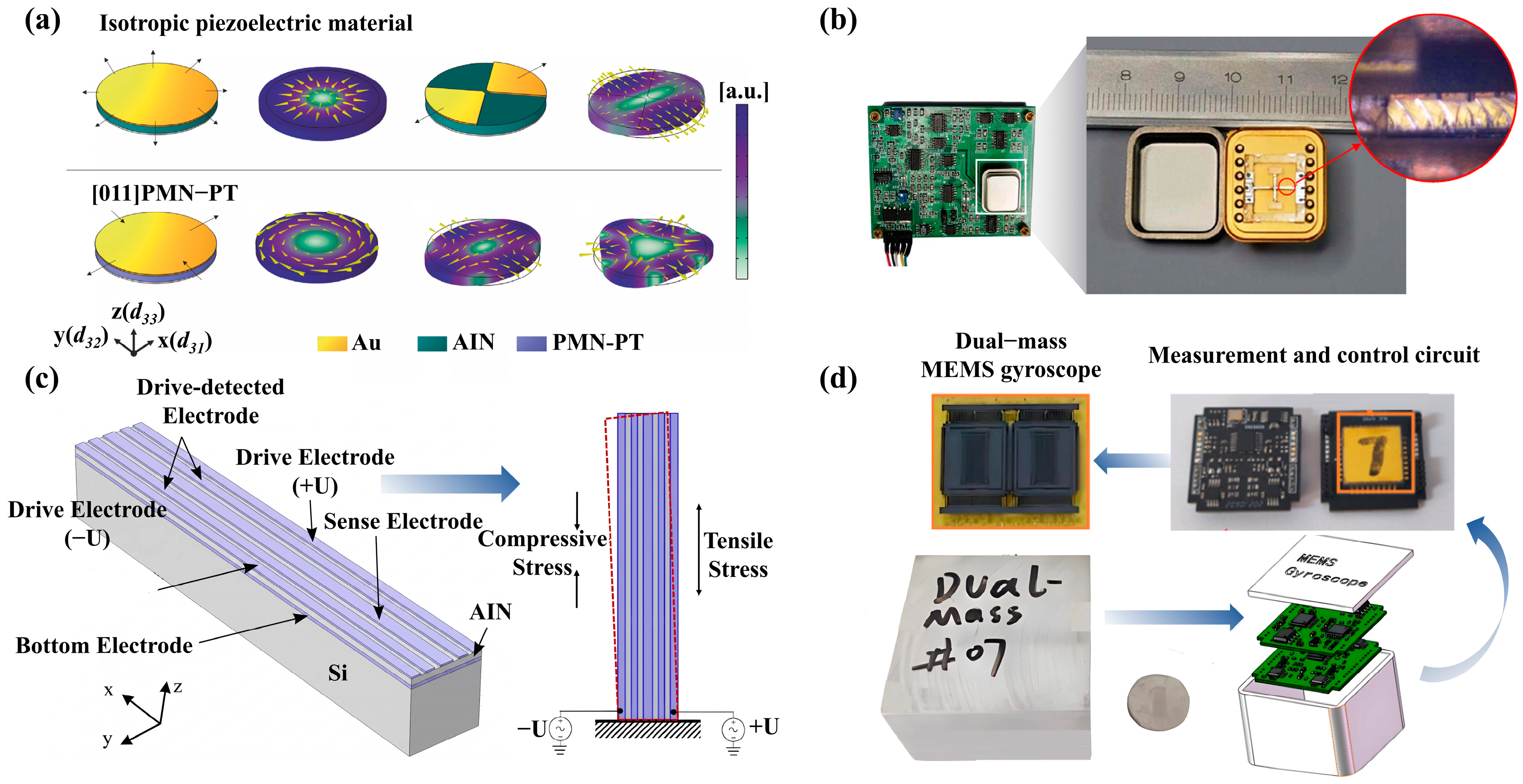
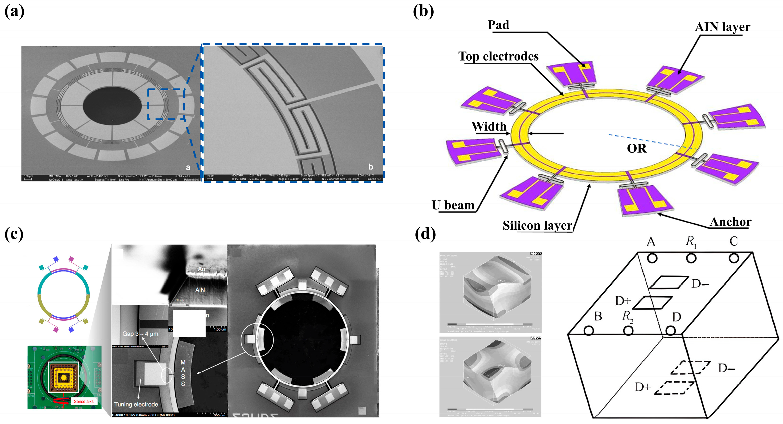
In 2020, in order to achieve vibration mode matching for the two wine-glass modes in a disc-type gyroscope, Obitani K et al. [51,52] utilised a 155°-Y-cut lithium niobate wafer to fabricate a piezoelectric disc-type gyroscope with gold electrodes using standard photolithography and core drilling processes. Angular velocity detection was performed via the gyroscope’s closed-loop drive and open-loop detection system, and the device operated successfully. It has been widely applied in fields such as autonomous driving. The resonant frequency of the cup mode in the fabricated lithium niobate disc gyroscope was 95 kHz, with a measured proportional factor of 0.35 μV/°/s and a zero-bias stability of 640°/h. Similarly, in 2023, Erturk et al. [53] developed a piezoelectric disc resonant gyroscope (Figure 4a) using PMN-PT (lead magnesium niobate-lead titanate) piezoelectric single crystals. This device utilises the unique in-plane piezoelectric anisotropy of PMN-PT to directly excite the n = 2 wineglass vibration mode (WGM) using only a single self-aligned, unpatterned electrode. This significantly simplifies the electrode fabrication process and reduces alignment difficulties, providing a new technical solution for the miniaturisation of piezoelectric disc gyroscopes and the simplification of manufacturing processes.

4.2.2. Tuning-Fork Gyroscope

Tuning-fork gyroscopes, as a key component of vibrating gyroscopes, primarily comprise single-ended tuning forks, double-ended tuning forks and other specialised configurations. In the case of the commonly used double-ended tuning fork, when the upper prong of the gyroscope is driven, the prongs undergo reciprocating motion; this is known as the drive mode. When an angular velocity ω is applied along the length of the gyroscope, a Coriolis force F is generated, causing the lower prongs to vibrate perpendicular to the surface of the gyroscope; this is known as the sensing mode. Tuning-fork gyroscopes have attracted widespread attention and research both domestically and internationally due to their characteristics of being lightweight, compact, long-lasting, and suitable for mass production [57]. In 2010, Xie et al. [54] and colleagues utilised a double-ended tuning fork structure to detect the Coriolis force via shear stress. The novel quartz microgyroscope they developed (Figure 4b) possesses a high quality factor (1000), thereby eliminating the need for complex vacuum encapsulation processes [58].

4.2.3. Beam Gyroscope

In 2001, Ma et al. [59] developed a four-beam microgyroscope. The structure features a suspended mass at its centre in the form of an inverted quadrangular pyramid; the base is connected to the central mass via beams coated with a PZT film. Through the inverse piezoelectric effect, the vibrations of beams 1 and 3 drive the central mass to move; the resulting Coriolis force causes beams 2 and 4 to bend and vibrate, thereby generating an output signal. This design features a simpler structure and a higher fabrication success rate, whilst offering a wider linear response range to the input angular velocity.
In 2020, Zhang Kangkang et al. [60] developed a novel beam-type piezoelectric gyroscope featuring a lithium niobate plate with an inversion layer: in a conventional lithium niobate plate, the inversion layer is formed by the reversal of electric domains; its piezoelectric properties are exactly opposite to those of the conventional layer, whilst its elastic and dielectric properties are identical to those of the conventional layer. It consists of two inverted-layer lithium niobate plates bonded together, with drive electrodes applied at x = −a and x = −a + 2b, and detection electrodes applied at x = ±a. When a voltage V2 is applied to the drive electrodes, it causes the beam to undergo bending vibration; when the beam rotates about the x1 axis at an angular velocity ω, the Coriolis force induces a second bending vibration in the beam, producing an output voltage V3. They found that the output voltage is related to both the drive frequency and the angular velocity, and that the closer the drive frequency is to the resonance frequency, the greater the value of V3/V2.
Yang J et al. [55] have also proposed a novel design for an aluminium nitride–silicon composite cantilever gyroscope (Figure 4c), which excites the cantilever to oscillate in-plane by applying two opposite voltages to two parallel drive electrodes. The drive mode frequency can reach 87.422 kHz, and the theoretical sensitivity can reach 0.145 pm/°/s.

4.2.4. Mass-Coupled Gyroscope

To improve vibration robustness, in 2023 Cui R et al. [56] designed a MEMS gyroscope with a fully decoupled dual-mass structure (Figure 4d). This symmetrical coupling structure achieves mutual cancellation of common-mode interference through mechanical decoupling, significantly reducing the sensor’s sensitivity to external vibrations and shocks. Drawing on this design philosophy, in 2024 Ontronen A et al. [61] designed a piezoelectric frequency-modulated (FM) gyroscope employing a four-mass coupled structure. This configuration cancels out common-mode interference, thereby reducing the sensor’s sensitivity to vibration. Although the measured ARW was relatively high (111 mdps/√Hz), the zero-bias stability was only 5°/h.

4.2.5. Ring Gyroscope

A ring-shaped MEMS gyroscope is a two-dimensional, plane-axis-symmetric gyroscope; through improvements in design and manufacturing processes, it is possible to reduce manufacturing costs and enhance structural reliability. In the 1990s, Ayazi F et al. [62] invented a polycrystalline silicon ring-shaped gyroscope manufactured using HARPSS technology. It consists of a ring, eight semi-circular support springs, and drive, sensing and control electrodes. With a capacitive gap of 1.4 μm, the gyroscope achieves a sensitivity of 200 μV/°/s under low-vacuum conditions.
Most of these ring-shaped MEMS gyroscopes are capacitive MEMS gyroscopes; however, in order to improve sensitivity, capacitive MEMS gyroscopes often require extremely small capacitive gaps in their design. This makes them highly susceptible to short circuits or structural damage when subjected to strong impacts or vibrations, rendering the gyroscope inoperable. In contrast to capacitive MEMS gyroscopes, piezoelectric MEMS gyroscopes are piezo-driven and do not require small capacitive gaps; consequently, they are expected to resolve the reliability issues associated with capacitive MEMS gyroscopes. They hold broad prospects for future development in fields requiring high reliability and miniaturisation within complex environments.
Building on this, in 2020, Ayazi F’s team [63] proposed a ring-shaped resonant gyroscope based on AlN piezoelectric thin films (Figure 5a). This gyroscope is fabricated using an AlN -on-Si process, with its core comprising an axisymmetric ring resonator, coupled with eight sets of symmetrical piezoelectric electrodes to perform both driving and detection functions. It does not require the fabrication of narrow capacitive gaps or the application of a DC polarisation voltage, which significantly reduces the complexity of the fabrication process whilst enhancing the reliability of the device.
In 2026, Qi et al. [64] designed a high-performance piezoelectric ring-shaped MEMS gyroscope (Figure 5b), utilising a single-crystal silicon crystal with the ⟨111⟩ orientation as the support platform for the ring-shaped resonant structure. An AlN piezoelectric thin film deposited on the surface of the silicon-based ring structure served as the transducer, with piezoelectric drive and detection achieved via 16 sector-shaped electrodes. Through finite element analysis, the researchers systematically investigated the influence of geometric parameters, such as ring width, on the quality factor and piezoelectric conversion efficiency, and found that a pore-free structural design could effectively suppress thermoelastic damping (TED) and maintain in-plane stress continuity. Meanwhile, Qi et al. employed a back-etching release process to replace the traditional front-side release holes, significantly reducing thermoelastic damping whilst maintaining structural integrity, resulting in a gyroscope quality factor of 75,000, an angular random walk of 0.34°/√h in open-loop rate mode, and a zero-bias instability of 8.19°/h.
In addition to traditional piezoelectric ring gyroscope designs, in 2024 Qi Z et al. [65] proposed a novel piezoelectric micro-electro-mechanical system (MEMS) pitch/roll gyroscope (Figure 5c), integrating both piezoelectric and electrostatic effects. This marked the first realisation of electrostatic mode-matched operation in a piezoelectric gyroscope. A 1 μm-thick AlN film was deposited on a highly doped silicon substrate, with a total device layer thickness of 25 μm. The mass block was fixed to the base via anchor points to sense the Coriolis force, with piezoelectric electrodes positioned on both sides of the mass block. By configuring electrostatic parallel-plate electrodes in the in-plane (IP) mode, the electrostatic effect is utilised to tune the natural frequency of the IP mode, thereby achieving the matching of the natural frequencies of the in-plane (IP) and out-of-plane (OOP) modes. Concurrently, to enhance the electromechanical coupling coefficient of the piezoelectric material whilst minimising cross-coupling, four OOP electrodes and four IP electrodes are positioned at the nodes of the OOP and IP modes.

4.2.6. Piezoelectric Solid-State Gyroscope

Unlike other conventional micro-mechanical gyroscopes, the piezoelectric solid-state gyroscope (Figure 5d) features a simple structure. When the longitudinal vibration excited on the surface of a rectangular prism is used as the reference vibration, applying angular velocity along the x-axis or y-axis results in a differential voltage output at the sensing electrodes on the PZT surface. This design enables the gyroscope to simultaneously detect angular velocities along both axes; furthermore, owing to its simple architecture and the absence of a suspension structure, it exhibits exceptional shock resistance [66].
Table 3 summarises the performance characteristics of representative piezoelectric gyroscope prototypes reported in the literature. It is important to note that, to date, all listed prototypes have been characterised exclusively at room temperature (RT); none has undergone systematic performance evaluation at elevated temperatures. This observation underscores a critical gap in the field: while piezoelectric materials such as AlN and LiNbO3 possess intrinsic high-temperature capability, the gyroscope prototypes themselves have not yet been validated under the thermal conditions encountered in target industrial applications.
The absence of high-temperature performance data represents a significant limitation of the current state of the art. Future research must prioritise elevated-temperature characterisation of these prototypes to establish their true operational boundaries and to identify failure modes that may emerge only under thermal stress. Such validation is essential before these devices can be deployed in industrial applications where ambient temperatures routinely exceed 200 °C.
It is important to emphasise that the temperature ranges reported for existing piezoelectric gyroscope prototypes (typically −40 to 60 °C, −25 to 70 °C, −45 to 85 °C, or 25 to 125/150 °C) fall far short of the 200–300 °C downhole environments discussed in Section 5. This discrepancy is not merely a matter of degree; it reflects a fundamental gap between laboratory characterisation and the harsh thermal conditions encountered in industrial deployment. Furthermore, to date, no complete gyroscope system has been demonstrated to maintain stable bias, ARW, scale factor, bandwidth, and reliability under true high-temperature conditions (≥200 °C).

5. Analysis of Application Scenarios and Requirements in the Industrial Sector

The industrial sectors reviewed in this section impose diverse and stringent environmental demands on inertial sensors. Table 4 summarises the key environmental parameters and performance requirements for each application domain, drawing upon the operating conditions described in the cited literature. These specifications provide the design targets against which current and future high-temperature piezoelectric gyroscope technologies must be evaluated. Values in parentheses indicate representative targets inferred from industry standards and the reviewed literature;—indicates parameters not explicitly quantified in the cited sources.
Several critical observations emerge from this comparison. First, temperature requirements span two orders of magnitude, from moderate heating in manufacturing processes (>200 °C) to extreme thermal environments near aeroengine combustion zones (>1000 °C). Second, all applications demand some degree of vibration immunity, reflecting the industrial reality of rotating machinery, drilling dynamics and fluid flow. Third, and most significantly, none of the existing piezoelectric gyroscope prototypes listed in Table 3 has been characterised at the elevated temperatures required by any of these applications; the gap between laboratory demonstration and field deployment remains the defining challenge for this technology.

5.1. Oil and Gas Exploration

MWD and LWD are commonly used downhole monitoring techniques in oil and gas drilling, primarily employed to obtain real-time data on wellbore inclination, azimuth and formation parameters, thereby facilitating more effective geological steering and rotary steering operations. As domestic drilling operations continue to extend into deep and ultra-deep zones, downhole conditions are becoming increasingly harsh. SU et al. [68] point out that in wells over 10,000 metres deep, bottom-hole temperatures can exceed 200 °C, pressures can reach over 200 MPa, and these conditions are accompanied by strong vibrations and significant shocks. In ultra-deep wells and dry hot rocks, environmental conditions are even more severe, with bottom-hole temperatures reaching 250 °C [69].
In such environments, the magnetic measurement methods relied upon by conventional MWD systems struggle to meet practical requirements. Ledroz et al. [70] pointed out that geomagnetic interference, such as the magnetisation of underground ore bodies and drill pipes, can cause significant errors in magnetometers or even render them completely inoperative; If non-magnetic drill collars are installed to suppress interference, this not only increases costs and the weight of the drill string, but also requires the sensor to be mounted approximately 15 m away from the drill bit, making it difficult to meet the requirements for precise near-bit steering. In contrast, a gyroscope-based inertial measurement unit (IMU) does not rely on the geomagnetic field and can independently calculate the drill string heading and wellbore inclination, making it a highly viable alternative to magnetic measurement.
However, inertial measurement near the drill bit still faces practical challenges. Research by Yang et al. [71] indicates that the significant vibrations and shocks near the drill bit cause gyroscopes to drift easily; relying solely on inertial navigation makes it difficult to meet accuracy requirements. Typically, a combination of magnetometer and inertial measurements, coupled with filtering algorithms, is required to calculate attitude with reasonable reliability. Furthermore, existing FOG inclinometers are bulky and costly, and the optical fibres are prone to degradation at high temperatures; whilst conventional MEMS gyroscopes are compact, they exhibit poor zero-bias stability at high temperatures. Overall, solid-state gyroscopes with a simple structure, high vibration resistance and high-temperature tolerance represent a promising direction for this application.
On the other hand, on-site requirements for well logging during drilling are becoming increasingly stringent; it is no longer sufficient to merely log inclination and azimuth, but rather it is necessary to simultaneously collect a variety of data, including attitude, vibration, temperature and pressure. Li et al. [72] point out that modern intelligent drilling systems require the integration of multi-source information within the same wellbore to enable real-time diagnosis of drilling conditions and risk early warning. This necessitates that inertial sensors not only withstand high temperatures but also feature miniaturisation, low power consumption and ease of integration; these requirements align closely with the characteristics of piezoelectric gyroscopes [73,74].

5.2. Geothermal Development and Scientific Drilling

The challenge of high temperatures in subsurface environments is not limited to oil and gas drilling; similar high-temperature conditions are also encountered in the development of geothermal energy from hot dry rock. Yuan et al. [75] point out that whilst China possesses vast reserves of hot dry rock, the commercial development of this resource still faces technical bottlenecks such as high-temperature drilling. For instance, Xu et al. [76] have noted that the geothermal gradient is approximately 3 °C/100 m; temperatures in deep well sections beyond 3000 m can reach over 90 °C, approximately 150 °C at 5000 m, and even exceed 250 °C in ultra-deep wells; simultaneously, magnetic anomalies in the ore body and the magnetisation of drilling tools can render magnetic navigation ineffective, making gyroscope-based inertial navigation systems the primary means of wellbore trajectory control. However, existing FOG inclinometers are not well-suited for use in high-temperature wells. Analysis by Liu et al. [77] indicates that fibre-optic gyroscopes are highly sensitive to temperature changes; when the external temperature reaches 270 °C, a metal vacuum flask is required to maintain the internal temperature below 125 °C. This inevitably increases the instrument’s size and cost, whilst also posing potential risks to long-term reliability. Research by Zhao et al. [78] also indicates that in ultra-deep high-temperature and high-pressure (HPHT) wells, downhole sensors frequently fail due to excessive temperature and pressure, leading to the loss of real-time measurement data; this further highlights the stringent requirements placed on the temperature resistance and long-term stability of inertial sensors in high-temperature deep-well environments. Similarly, Reinsch et al. [79], in their high-temperature testing of temperature-sensing optical fibres for geothermal wells, found that polyimide-coated optical fibres exhibit irreversible increases in both coating degradation and transmission loss under sustained high temperatures. This indicates that not only are fibre-optic gyroscopes constrained in high-temperature deep wells, but other fibre-optic sensing components also struggle to operate stably over the long term. Consequently, the fields of geothermal development and scientific drilling do indeed require solid-state inertial sensors capable of operating directly at temperatures above 200 °C without the need for complex thermal insulation measures; piezoelectric gyroscopes, owing to their all-solid-state structure and absence of fibre-optic loops, possess excellent high-temperature adaptability and therefore hold promising prospects for application in this regard.

5.3. Nuclear Power Generation

Condition monitoring in nuclear facilities faces environmental constraints as severe as those encountered in geothermal drilling. In their review of measurement technologies for nuclear facilities, Wang et al. [80] noted that temperature is a critical monitoring parameter for nuclear reactors; however, traditional high-temperature thermocouples are prone to significant drift due to material deformation in harsh nuclear environments, whilst fibre-optic sensors must overcome signal attenuation caused by radiation-induced absorption. This implies that as reactor operating temperatures rise, the requirements for sensor temperature resistance and radiation resistance become increasingly critical; piezoelectric gyroscopes, being all-solid-state devices that do not require complex shielding, are therefore equally worthy of exploration in the context of monitoring nuclear power generation facilities.
Inertial sensors in the nuclear sector also face the dual challenges of high temperatures and radiation. Zhang et al. [81] pointed out that silicon-based MEMS suffer from P-N junction leakage current due to a surge in intrinsic carriers at temperatures exceeding 120 °C, resulting in severe performance degradation; In contrast, SiC has a bandgap approximately 2–3 times wider than that of silicon, and a critical displacement energy approximately twice that of silicon, offering superior resistance to high temperatures and radiation. Therefore, replacing silicon with wide-bandgap materials such as SiC to construct solid-state gyroscopes holds practical significance for attitude monitoring in high-temperature zones of nuclear facilities.

5.4. Aviation Engines and High-Temperature Manufacturing

Industrial high-temperature environments are not limited to underground spaces and nuclear facilities; hot-end components of aircraft engines (such as combustion chambers and turbine blades) can operate at temperatures exceeding 1000 °C, and their health monitoring requires the acquisition of vibration and attitude data in the vicinity of these high-temperature zones. High-temperature manufacturing processes, such as continuous casting in metallurgy and heat treatment furnaces, also demand reliable inertial measurements in environments reaching hundreds of degrees Celsius. However, the application of existing inertial sensors in such scenarios remains limited, primarily due to performance degradation and packaging failure caused by high temperatures. Research by Mei et al. [82] on control moment gyroscopes for spacecraft also indicates that even a temperature rise of just a few degrees Celsius, coupled with uneven temperature distribution, can affect the stability and operational lifespan of the gyroscope. This demonstrates that temperature has a significant impact on gyroscope-type sensors; in high-temperature environments such as aircraft engines and high-temperature industrial equipment, the requirements for sensor temperature resistance and thermal stability are correspondingly higher.
Fibre-optic gyroscopes also face limitations in this regard; resonant fibre-optic gyroscopes (RFOGs), as the second generation of fibre-optic gyroscopes, offer advantages in terms of optical stability and system miniaturisation. Wang et al. [83] point out in their review that RFOGs are currently still constrained by optical noise such as polarisation noise, backscatter noise and the optical Kerr effect, and that the resonant cavity is relatively sensitive to temperature changes, typically requiring temperature control devices to maintain stability. These noise sources and temperature control requirements are further amplified in high-temperature environments, limiting the application of RFOGs in scenarios such as aircraft engines and high-temperature industrial equipment. Consequently, the development of solid-state gyroscopes with simpler structures and high-temperature resistance remains a direction worthy of attention.

6. Technical Challenges and Optimisation Strategies for Piezoelectric Gyroscopes in High-Temperature Environments

The analysis of industrial demand in the previous chapter indicates that sectors such as oil drilling, geothermal development, nuclear energy and aero-engine manufacturing all have clear requirements for high-temperature-resistant solid-state inertial sensors. However, judging by current technological approaches, whether it be the temperature control dependencies of fibre-optic gyroscopes or the high-temperature failure of silicon-based MEMS, these issues essentially stem from the detrimental effects of temperature fluctuations on the physical structure and operating mechanisms of the sensors. In the case of piezoelectric gyroscopes, although their all-solid-state structure offers certain advantages in terms of material temperature resistance, temperature variations can still affect the gyroscope through mechanisms such as thermal expansion and material parameter drift, leading to issues such as zero-bias drift, reduced sensitivity and increased orthogonal error. It is therefore necessary to systematically analyse, at a mechanistic level, the specific pathways through which temperature affects the performance of piezoelectric gyroscopes, and to explore targeted strategies for material selection and structural optimisation.
In addition to the temperature-induced performance drift discussed above, the long-term reliability of piezoelectric gyroscopes is critically affected by material aging and cyclic thermomechanical fatigue. For PZT-based devices, repeated thermal cycling above 120 °C accelerates domain-wall depinning and electrode degradation, leading to irreversible reductions in d33 and increased dielectric loss. AlN thin films, whilst intrinsically stable to >1000 °C, are susceptible to thermally activated oxidation at the AlN–Si interface under prolonged thermal exposure, gradually degrading the electromechanical coupling coefficient. Single-crystal LiNbO3 exhibits superior aging resistance; however, its supporting Si substrate and metallised interconnects remain weak points under cyclic thermal stress. Crucially, systematic long-term resource tests (>1000 h) and accelerated cyclic fatigue protocols have not yet been reported for any piezoelectric gyroscope prototype, and failure-mode statistics are essentially absent from the literature. This gap represents a major barrier to technology transfer from laboratory demonstration to industrial deployment.

6.1. Structural Design and Optimisation

Temperature variations have a significant effect on gyroscopes. Due to differences in the thermal expansion coefficients of various materials, temperature changes cause alterations in the gyroscope’s geometric symmetry and associated physical properties, leading to a shift in vibration modes. This, in turn, enhances the mechanical coupling between the drive mode and the sensing mode. This mechanical coupling generates orthogonal errors, meaning that when the gyroscope is at rest, spurious output signals appear in the detection direction, interfering with the actual detection signal output. Therefore, reducing mechanical coupling is a key technology for ensuring that the gyroscope can be precisely controlled [84].
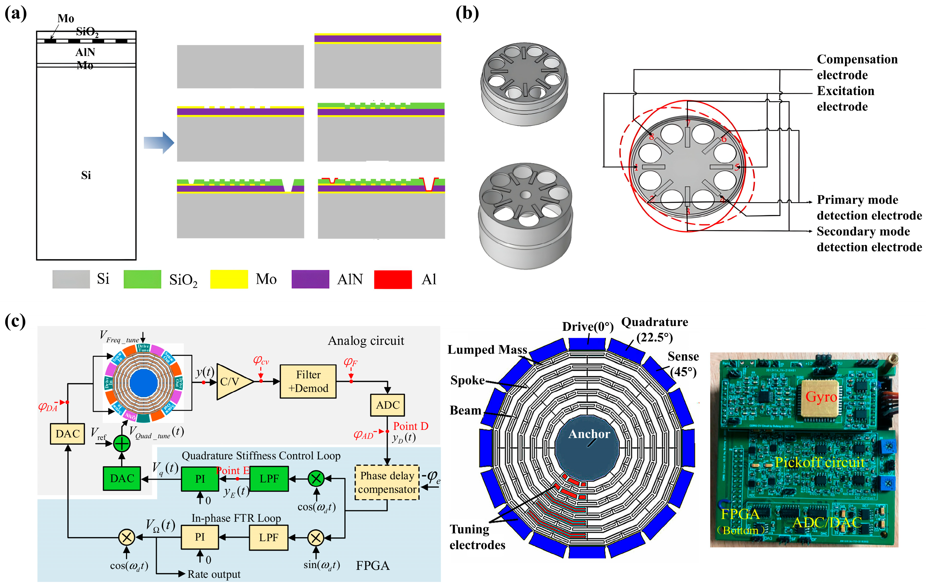
To improve the temperature stability of the gyroscope whilst optimising its immunity to interference, Yang S et al. [85] designed a resonator featuring a twelve-pair dog-leg symmetrical strut support structure based on the split-mode problem of MEMS vibrating gyroscopes, Using an AlN piezoelectric thin film as the sensing layer, and through design optimisation of the dog-leg symmetric cantilever support structure, the frequency splitting (∆f/fs) was reduced to 11.2 ppm, significantly reducing mutual interference between the gyroscope’s vibration modes, thereby improving the gyroscope’s mechanical proportional factor (SFmech) and reducing the mechanical noise equivalent rate (ΩMNER). Concurrently, passive temperature compensation was achieved by incorporating a highly n-doped (4.75 × 10¹⁹/cm3) silicon layer and an oxide layer into the structure. Within the temperature range of 25 °C to 125 °C, the maximum variation in relative frequency splitting was 12.32 ppm, significantly improving its temperature stability. Similarly, Chen et al. [67] conducted a systematic three-dimensional finite element analysis of a quasi-surface acoustic wave (QSAW) resonator employing an AlN/Mo/Si stacked-layer structure (Figure 6a), verifying the electromechanical coupling characteristics and temperature stability of the AlN piezoelectric thin film within the resonator. Their study demonstrated that the structure exhibits good frequency stability within the temperature range of 30 °C to 150 °C.
Similarly, to enhance structural symmetry, Thomas Perrier et al. [86] designed a novel axisymmetric quartz MEMS gyroscope featuring a momentum-compensated structure. This structure utilises the symmetry of the Y-shaped connecting element to ensure that the mass blocks distribute energy uniformly at different temperatures, thereby preventing shifts in vibration modes caused by temperature variations. This ensures that the vibration characteristics of the gyroscope’s drive and sensing modes remain consistent across different temperatures, effectively enhancing the gyroscope’s thermal stability. At the same time, the Y-shaped structure reduces the energy transmitted to the frame via the anchor points, thereby lowering the thermoelastic damping caused by energy loss and effectively improving the gyroscope’s quality factor. Similarly, Qu et al. [87] conducted research on a high-temperature sintering process for electrodes in cylindrical shell piezoelectric gyroscopes (Figure 6b). They employed an axisymmetric structure combining a cylindrical quartz resonator with PZT-5H piezoelectric ceramic electrodes, directly bonding the piezoelectric electrodes to the resonator body via a high-temperature sintering process at 1050 °C. Experiments demonstrated that this piezoelectric gyroscope exhibits good frequency consistency between the drive and sense modes within the temperature range of −40 °C to 60 °C, validating the feasibility of the axisymmetric structure combined with the high-temperature sintering process in enhancing the thermal stability of piezoelectric gyroscopes [88,89].
Figure 6. (a) Simplified 2D FEA model structure and the process flow of the QSAW resonators. Reprinted with permission from Ref. [67]. Copyright 2021, MDPI AG. (b) Schematic diagram of a cylindrical resonator and piezoelectric electrodes. Reprinted with permission from Ref. [87]. Copyright 2020, MDPI AG. (c) The control scheme of the Mode II closed-loop gyroscope system, the Structure of the CDRG and the control circuit. Reprinted with permission from Ref. [90]. Copyright 2022, MDPI AG.
Coatings 16 00810 g006

6.2. Circuit Design and Temperature Compensation

Although structural optimisation and passive temperature compensation are highly effective methods, many researchers also choose to improve the temperature stability of gyroscopes by optimising the circuitry. Descharles M et al. [91] designed a closed-loop feedback circuit for a single-ended tuning-fork quartz micro-mechanical gyroscope to dynamically reduce quadrature error. By continuously measuring the quadrature output signal and feeding it back into a control loop, whilst using a PID controller to actively adjust the injection gain, the quadrature component Q is maintained at zero. This active gain system significantly improves thermal stability at different temperatures, achieving a zero-bias stability of 20°/h RMS within the temperature range of −25 °C to +70 °C. Furthermore, Bu et al. [91] investigated the effect of quadrature error on zero drift in piezoelectric cylindrical disk resonator gyroscopes (CDRG) and proposed an online compensation method (Figure 6c), They proposed a closed-loop temperature compensation system incorporating an orthogonal PI controller. By adjusting the orthogonal correction voltage in real time during temperature variations, they effectively suppressed zero drift caused by orthogonal errors, reducing the gyroscope’s zero-bias instability from 1.28°/h to 0.23°/h, thereby significantly enhancing the gyroscope’s operational stability across varying temperature environments.
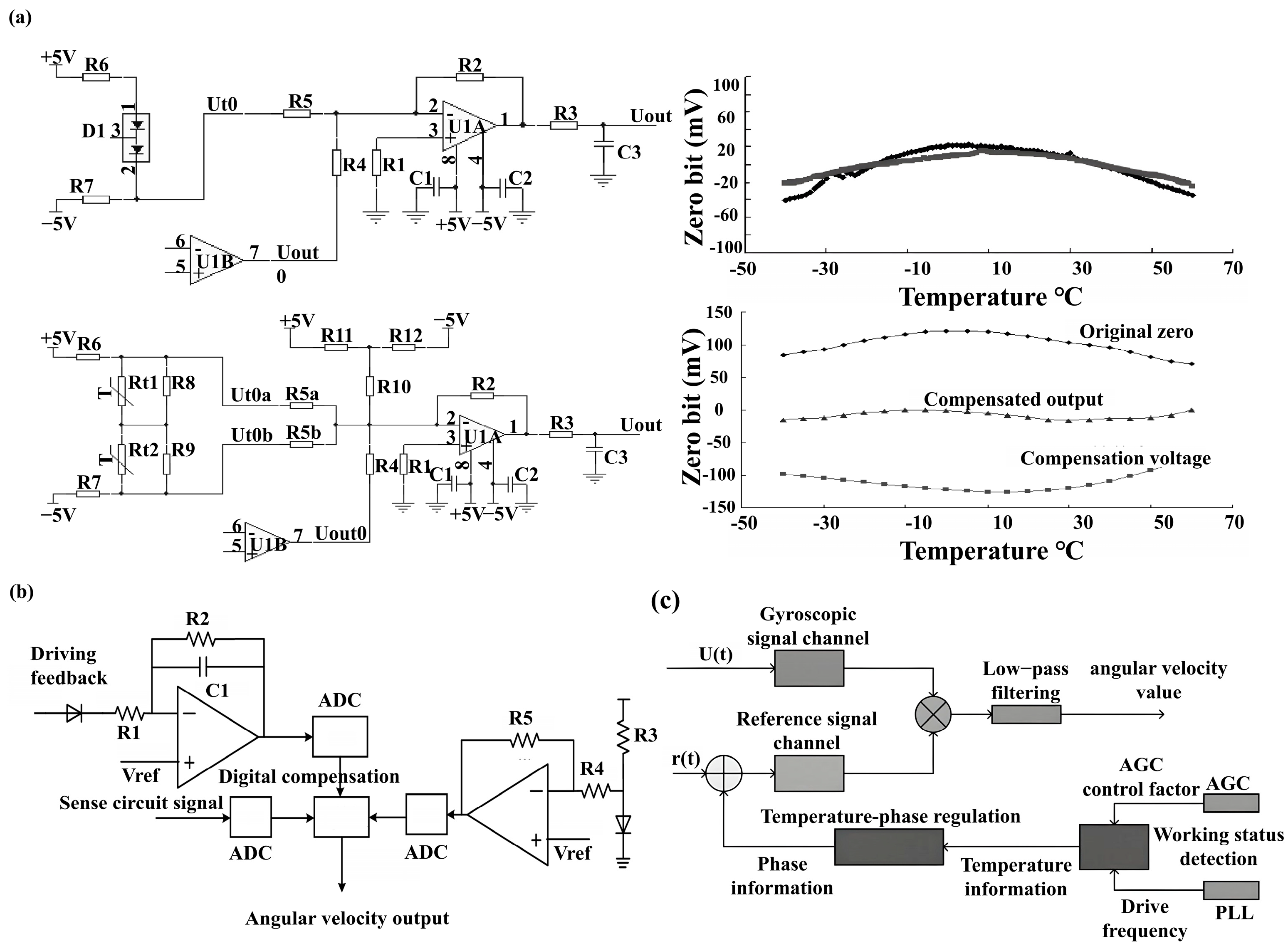
During the process of temperature compensation via a circuit, the temperature characteristics of the components have a direct impact on the circuit. In response to this, Li et al. [92] designed two compensation circuits (Figure 7a). One of these involves adding a diode (BAV99) to the signal processing circuit. By utilising the characteristic that its voltage drop decreases as the temperature rises, the compensated zero-voltage value is reduced to at least one-third of the pre-compensation value across the entire temperature range of −40 °C to 60 °C. The other employs thermistors with negative and positive temperature coefficients to design a compensation circuit capable of exhibiting an approximate U-shaped temperature characteristic, thereby also achieving a satisfactory temperature compensation effect.
In addition to analogue circuits, signal processing and control logic based on digital circuit design offer greater precision and flexibility. Consequently, Di X et al. [93] designed a fully digital application-specific integrated circuit (ASIC) and, by employing an on-chip digital temperature compensation method based on the amplitude of the drive signal, achieved a BI output of 16°/h for the gyroscope within the temperature range of −45 °C to 85 °C, thereby significantly improving its temperature stability. Furthermore, Zhang et al. [94] developed an interface ASIC (Figure 7b) for MEMS gyroscopes that integrates analogue closed-loop drive with digital temperature compensation. This circuit employs an AGC self-oscillating closed-loop drive scheme to replace the traditional PLL, effectively improving temperature adaptability. It also utilises the positive and negative temperature characteristics of diodes to achieve on-chip temperature detection, and integrates a digital temperature compensation module to perform real-time correction of temperature drift and zero-offset in the angular velocity output. Test results indicate that, when fabricated using a standard 0.18 μm CMOS BCD process, this interface ASIC achieves a system non-linearity of 0.03% across the full range and a zero-drift instability of 5.1 °/h. These digital temperature compensation methods based on application-specific integrated circuits provide effective technical solutions for optimising circuit-level temperature stability in high-temperature piezoelectric gyroscopes.
In China, Feng Lihui et al. [95] utilised AGC to achieve temperature self-sensing, whilst simultaneously suppressing temperature-induced quadrature error by controlling the phase of the reference signal in real time (Figure 7c). Using this method, the gyroscope’s self-sensing accuracy reached 1.73 °C within the range of −40 °C to 80 °C, and zero-bias stability improved from 192.85°/h to 5.03°/h.
Figure 7. (a) The circuit principle of linear compensation for zero-point temperature error and the results of linear compensation for gyroscope zero-point temperature error. Reprinted with permission from Ref. [92]. Copyright 2015, Piezoelectrics & Acoustooptics. (b) Circuit diagram of digital temperature compensation. Reprinted with permission from Ref. [94]. Copyright 2023, MDPI AG. (c) Schematic diagram of the temperature compensation method and a comparison of the gyroscope’s zero bias before and after compensation. Reprinted with permission from Ref. [95]. Copyright 2020, Automation and Instrumentation.
Coatings 16 00810 g007

6.3. Machine Learning and Artificial Intelligence Approaches

Recent advances in machine learning (ML) and artificial intelligence (AI) have opened new avenues for enhancing the performance and reliability of gyroscopes in high-temperature environments. These data-driven approaches complement traditional hardware-based compensation methods (Section 6.1 and Section 6.2) and offer adaptive capabilities that are particularly valuable in harsh industrial settings where temperature fluctuations are unpredictable. Cohen and Klein [96] provided a comprehensive survey of deep learning methods for inertial sensing, categorising approaches into calibration and denoising, pure inertial navigation improvement, and aided navigation filter parameter optimisation. This section examines the application of ML/AI techniques across four domains relevant to high-temperature piezoelectric gyroscopes: temperature drift compensation, mode matching, sensor fusion, and fault diagnosis.

6.3.1. Temperature Drift Prediction and Compensation

Temperature-induced drift remains one of the most significant challenges for piezoelectric gyroscopes in industrial applications. Conventional polynomial or linear compensation models often fail to capture the complex, nonlinear relationship between temperature and gyroscope output. To address this limitation, researchers have increasingly turned to neural network-based approaches. Tan et al. [97] proposed a temperature compensation model for dual-mass vibration MEMS gyroscopes integrating time-scale transformation-assisted optimised variational mode decomposition (TTAO-VMD) with a one-dimensional convolutional neural network-bidirectional gated recurrent unit-attention (1D-CNN-Bi-GRU-Attention) architecture and an adaptive Kalman filter, achieving a reduction in angle random walk from 18.56°/h to 0.17°/h. Zhang et al. [98] employed improved complete ensemble empirical mode decomposition with adaptive noise (ICEEMDAN) combined with an extreme learning machine optimised by the non-dominated sorting genetic algorithm II (NSGA-II), reducing bias stability from 32.7°/h to 0.26°/h. Cao et al. [99] developed a TFPF-MEA-BP algorithm combining time-frequency peak filtering with a mind evolutionary algorithm-optimised backpropagation network for dual-mass MEMS gyroscope temperature drift compensation. More recently, Ouyang et al. [100] proposed a combined long short-term memory-support vector machine-deep belief network (LSTM-SVM-DBN) algorithm for micromechanical gyroscope temperature compensation, demonstrating the effectiveness of hybrid deep learning architectures in this domain. These studies collectively demonstrate that ML-based approaches can reduce temperature drift errors by one to two orders of magnitude compared with traditional polynomial fitting, making them promising candidates for integration into high-temperature piezoelectric gyroscope systems.

6.3.2. AI-Assisted Mode Matching and Frequency Tuning

Resonance frequency matching between the drive and sense modes is critical for achieving high sensitivity and low bias instability in vibrating gyroscopes. Traditional mode-matching techniques rely on manual or semi-automatic electrostatic tuning, which is time-consuming and susceptible to temperature-induced frequency splitting. Machine learning offers a pathway to automate this process. Gu et al. [101] demonstrated a machine learning algorithm based on back-propagation neural networks for the structural design of MEMS resonators, which can predict resonant frequency, thermoelastic quality factor, mechanical sensitivity and mechanical thermal noise with regression accuracy exceeding 96%, whilst being over 11,000 times faster than traditional finite element simulation. Such ML-driven design optimisation can be extended to mode-matching control by training neural networks on historical temperature-frequency data to predict optimal tuning voltages in real time. Reinforcement learning algorithms have also been explored to dynamically adjust drive frequencies and track the optimal operating point across varying temperature ranges [102]. For piezoelectric gyroscopes in high-temperature environments, where thermal gradients cause continuous shifts in resonant frequencies, such AI-assisted approaches could maintain mode-matched conditions without constant manual intervention, thereby preserving sensitivity and stability throughout the operational temperature range.

6.3.3. Deep Learning for Sensor Fusion

Beyond individual gyroscope compensation, deep learning has shown significant potential in improving inertial navigation systems through intelligent sensor fusion. Wu et al. [103] proposed a multitask learning model to predict the noise covariance matrix of a Kalman filter in GNSS/INS integrated navigation, demonstrating that neural networks can effectively learn the complex statistical properties of sensor noise under varying operational conditions. Cohen and Klein [104] introduced the Adaptive Kalman-Informed Transformer (A-KIT), which employs attention mechanisms to capture long-range dependencies in inertial data and dynamically predict process noise covariance, outperforming conventional adaptive filtering approaches. For high-temperature industrial applications, these data-driven fusion techniques offer the potential to intelligently weight sensor contributions based on real-time environmental conditions, maintaining navigation accuracy even when individual sensors degrade under thermal stress. The integration of such methods with piezoelectric gyroscopes represents a promising direction for robust inertial sensing in extreme environments.

6.3.4. Intelligent Fault Diagnosis and Health Management

The reliability of gyroscopes in extreme environments is paramount for safety-critical applications such as nuclear facility monitoring and aircraft engine control. Machine learning enables data-driven fault diagnosis and remaining useful life (RUL) prediction by analysing patterns in sensor output that precede failure. Wu et al. [105] proposed a fault-attention generative probabilistic adversarial autoencoder (FGPAA) for machine anomaly detection, which automatically identifies low-dimensional manifolds in high-dimensional sensor signals and constructs abnormal state indicators from feature distribution probability and reconstruction error. Their model outperforms traditional methods in both classification accuracy and run-to-failure trend prediction, and can be processed in real time. For piezoelectric gyroscopes operating at elevated temperatures, integrating such ML-based health monitoring could enable predictive maintenance, reducing unplanned downtime and extending operational lifespan in harsh industrial settings. The combination of robust high-temperature materials (Section 3), optimised structural designs (Section 6.1), effective circuit compensation (Section 6.2), and intelligent AI-driven monitoring (this section) constitutes a comprehensive technological framework for deploying piezoelectric gyroscopes in demanding industrial applications.

7. The Potential Applications of High-Temperature Piezoelectric Gyroscopes in the Industrial Sector

In recent years, piezoelectric gyroscope technology has made significant progress. Compared with traditional silicon-based MEMS devices, piezoelectric materials possess a higher elastic modulus, are capable of precise vibration with a high quality factor, and exhibit excellent stability over a wide temperature range. Consequently, since the 1990s, piezoelectric gyroscopes have shown great potential for application in extreme environments such as the aerospace and defence sectors [106].
For example, Emcore has developed a tactical-grade inertial measurement unit (IMU) sensor based on Systron Donner Inertial technology, comprising three quartz MEMS gyroscopes and three quartz MEMS accelerometers. The quartz MEMS gyroscopes employ a dual-tuning-fork design, achieving a gyroscope bias stability of 0.1°/h RMS (+σ) within a temperature range of −55 °C to +85 °C. Furthermore, this new gyroscope architecture demonstrates a navigation-grade ARW of better than 0.001°/√h at a stable temperature, with a zero-bias stability of approximately 0.005°/h [107].

8. Conclusions

With the continuous evolution of industrial demands towards greater intelligence and precision, high-temperature piezoelectric gyroscopes, as key inertial sensor components, have attracted significant attention regarding their technological development and application prospects. State-of-the-art piezoelectric MEMS gyroscopes have demonstrated zero-bias stability as low as 5°/h and ARW of 0.34°/√h, with quality factors reaching 75,000 at temperatures up to 125 °C. Key materials such as PZT (d33 = 562 pC/N, Tc ~350 °C), LiNbO3 (Tc ~1210 °C), and AlN (Tc > 2000 °C) offer complementary advantages for high-temperature operation. Although existing research has made notable progress, challenges remain in terms of the ultimate performance of materials, system integration, and cross-disciplinary adaptability. In terms of materials and structural design, the high-temperature stability and sensitivity of current piezoelectric materials struggle to meet the long-term demands of extreme industrial environments above 200 °C. Consequently, future research must explore novel high-temperature piezoelectric composite materials and thin-film technologies, utilising microstructural control to enhance the materials’ temperature self-compensation capabilities [108,109,110,111]; In terms of environmental adaptability, piezoelectric gyroscopes for emerging extreme industrial applications must overcome limitations in radiation resistance and ultra-high-temperature tolerance. Advanced protective encapsulation and thermal management strategies represent important future research directions to extend operational lifespans in harsh environments.

Author Contributions

Conceptualization, X.L. and Q.L.; Methodology, X.L.; Writing—Original Draft, X.L.; Writing—Review & Editing, Q.L., S.Z. and L.Q.; Visualization, Y.H. and M.T.; Supervision, Q.L. and L.Q.; Funding Acquisition, Q.L. and L.Q. All authors have read and agreed to the published version of the manuscript.

Funding

This research was funded by the Beijing Natural Science Foundation (grant number L243022), the National Natural Science Foundation of China (grant number U2006218), and the Project of Construction and Support for High-Level Innovative Teams of Beijing Municipal Institutions (grant number BPHR20220124).

Institutional Review Board Statement

Not applicable.

Data Availability Statement

The data used to support the findings of this study are included in the article. Should further data or information be required, these are available from the corresponding author upon request.

Conflicts of Interest

The authors declare no conflicts of interest.

References

  1. Hunt, G.H.; Hobbs, A.E.W. Paper 4: Development of an Accurate Tuning-Fork Gyroscope. In Proceedings of the Institution of Mechanical Engineers, Conference Proceedings; Sage UK: London, UK, 1964; Volume 179, pp. 129–139. [Google Scholar]
  2. Bergh, R.; Lefevre, H.; Shaw, H. An Overview of Fiber-Optic Gyroscopes. J. Light. Technol. 1984, 2, 91–107. [Google Scholar] [CrossRef]
  3. Li, Y.; Liao, Q.; Hou, W.; Qin, L. Silver-Based Surface Plasmon Sensors: Fabrication and Applications. Int. J. Mol. Sci. 2023, 24, 4142. [Google Scholar] [CrossRef] [PubMed]
  4. Huang, W.; Yan, X.; Zhang, S.; Li, Z.; Hassan, J.N.A.; Chen, D.; Wen, G.; Chen, K.; Deng, G.; Huang, Y. MEMS and MOEMS Gyroscopes: A Review. Photonic Sens. 2023, 13, 230419. [Google Scholar] [CrossRef]
  5. Passaro, V.M.N.; Cuccovillo, A.; Vaiani, L.; De Carlo, M.; Campanella, C.E. Gyroscope Technology and Applications: A Review in the Industrial Perspective. Sensors 2017, 17, 2284. [Google Scholar] [CrossRef] [PubMed]
  6. Mevissen, S.J.; Klaassen, R.; van Beijnum, B.J.F.; Haarman, J.A.M. Eating Event Recognition Using Accelerometer, Gyroscope, Piezoelectric, and Lung Volume Sensors. Sensors 2024, 24, 571. [Google Scholar] [CrossRef] [PubMed]
  7. Barbour, N.; Schmidt, G. Inertial Sensor Technology Trends. IEEE Sens. J. 2002, 1, 332–339. [Google Scholar] [CrossRef]
  8. Su, Y.; Dou, X.; Gao, W.; Liu, K. Reflections on and Prospects for the Development of Logging-While-Drilling Technology in Oil and Gas Wells. Pet. Sci. Bull. 2023, 8, 535–554. [Google Scholar]
  9. Wu, J.; Gao, X.; Chen, J.; Wang, M.; Zhang, S.; Dong, S. High-Temperature Piezoelectric Materials, Devices and Applications. Acta Phys. Sin. 2018, 67, 10–39. [Google Scholar] [CrossRef]
  10. Salzenstein, P.; Kuna, A.; Sojdr, L.; Chauvin, J. Significant Step in Ultra-High Stability Quartz Crystal Oscillators. Electron. Lett. 2010, 46, 1433–1434. [Google Scholar] [CrossRef]
  11. Liao, Y.; Liao, Q.; Yin, Y.; Li, Y.; Du, M.; Zhao, H.; Li, L.; Wang, Y.; Qin, L. High Temperature Piezoelectric Properties and Ultra-High Temperature Sensing Properties of Bismuth Tungstate. J. Adv. Ceram. 2024, 13, 1931–1942. [Google Scholar] [CrossRef]
  12. Li, M.; Sun, Y.; Gao, S.; Zhao, X.; Hui, F.; Luo, W.; Hu, Q.; Chen, H.; Wu, H.; Wang, Y.; et al. Navigation-Grade Interferometric Air-Core Antiresonant Fibre Optic Gyroscope with Enhanced Thermal Stability. Nat. Commun. 2025, 16, 3654. [Google Scholar] [CrossRef]
  13. Schwartz, S.; Ravailled, A.; Feugnet, G.; Bretenaker, F. Analysis of the Design of a Passive Resonant Miniature Optical Gyroscope Based on Integrated Optics Technologies. Opt. Eng. 2017, 56, 107109. [Google Scholar] [CrossRef]
  14. Ma, H.; Wang, L.; Wang, X. Planar Photonic Gyroscopes for Satellite Attitude Control. In Proceedings of the 2017 7th IEEE International Workshop on Advances in Sensors and Interfaces (IWASI); IEEE: Piscataway, NJ, USA, 2017; pp. 167–169. [Google Scholar] [CrossRef]
  15. Tang, J.; Zeng, L.; Deng, K.; Li, J.; Xiao, P.; Xia, T.; Pan, Y.; Luo, H. A Rate Hemispherical Resonator Gyroscope with Bias Stability of 0.0056°/h with Compensation of Phase Delay. Sens. Actuators A Phys. 2024, 375, 115494. [Google Scholar] [CrossRef]
  16. Cao, H.; Wu, Y.; Chang, L.; Kong, Y.; Sun, H.; Wu, W.; Sun, J.; Zhang, Y.; Xi, X.; Miao, T. Autonomous Navigation of Unmanned Ground Vehicles Based on Micro-Shell Resonator Gyroscope Rotary INS Aided by LDV. Drones 2025, 10, 706. [Google Scholar] [CrossRef]
  17. Trusov, A.A.; Phillips, M.R.; Mccammon, G.H.; Rozelle, D.M.; Meyer, A.D. Continuously Self-Calibrating CVG System Using Hemispherical Resonator Gyroscopes. In Proceedings of the 2015 IEEE International Symposium on Inertial Sensors and Systems (INERTIAL), Kona, HI, USA, 23–26 March 2015; IEEE: Piscataway, NJ, USA, 2015; pp. 1–4. [Google Scholar] [CrossRef]
  18. Li, M.; Sun, Y.; Gao, S.; Zhao, X.; Hui, F.; Luo, W.; Hu, Q.; Chen, H.; Wu, H.; Wang, Y.; et al. A High-Performance Tactical-Grade Monolithic Horizontal Dual-Axis MEMS Gyroscope with Off-Plane Coupling Suppression Silicon Gratings. IEEE Sens. J. 2021, 21, 11765–11773. [Google Scholar] [CrossRef]
  19. Liu, Z.; Wen, H.; Ayazi, F. Multi-Coefficient Eigenmode Operation—Breaking Through 10°/h Open-Loop Bias Instability in Wideband Aluminum Nitride Piezoelectric BAW Gyroscopes. Microsyst. Nanoeng. 2023, 9, 18. [Google Scholar] [CrossRef]
  20. Tan, D.; Zhang, Q. Manufacturing Techniques for Quartz Micromechanical Inertial Sensors. Sens. World 2002, 8, 22–24. [Google Scholar]
  21. Liao, Q.; Hou, W.; Liao, K.; Chen, L.; Song, Y.; Gao, G. Solid-Phase Sintering and Vapor-Liquid-Solid Growth of BP@MgO Quantum Dot Crystals with a High Piezoelectric Response. J. Adv. Ceram. 2022, 11, 1725–1734. [Google Scholar] [CrossRef]
  22. Wang, J.; Zhou, Z.; Xu, C.; Xu, J.; Chen, Y. Li/Mn co-doped K0.5Bi4.5Ti4O15 high-temperature piezoelectric ceramics: Structures, properties, and ultrasonic transducer applications. J. Adv. Ceram. 2026, 15, 9221277. [Google Scholar] [CrossRef]
  23. Fadhlina, H.; Atiqah, A.; Zainuddin, Z. A Review on Lithium Doped Lead-Free Piezoelectric Materials. Mater. Today Commun. 2022, 33, 104835. [Google Scholar] [CrossRef]
  24. Habib, M.; Lantgios, I.; Hornbostel, K. A Review of Ceramic, Polymer and Composite Piezoelectric Materials. J. Phys. D Appl. Phys. 2022, 55, 423002. [Google Scholar] [CrossRef]
  25. Li, H.; Liu, J.; Li, K.; Deng, J.; Liu, Y. A Review of Recent Studies on Piezoelectric Pumps and Their Applications. Mech. Syst. Signal Process. 2021, 151, 107393. [Google Scholar] [CrossRef]
  26. Zhang, S.; Liao, Q.; Xu, Y.; Liu, X.; Zhang, H.; Wang, H.; Dong, H.; Qin, L. A-Site Doping Effect on PLZT Relaxor Ferroelectric Glass-Free Medium-Temperature Sintering Ceramics. Coatings 2025, 15, 1032. [Google Scholar] [CrossRef]
  27. Xu, Y.; Liao, Q.; Zhang, S.; Liu, X.; Zhang, H.; Qin, L. Amphoteric Doping Effect of Ho3+ on the Performance of Medium-Temperature-Sintered PLZT Energy Storage Ceramics. Coatings 2025, 15, 1067. [Google Scholar] [CrossRef]
  28. Setter, N.; Damjanovic, D.; Eng, L.; Fox, G.; Gevorgian, S.; Hong, S.; Kingon, A.; Kohlstedt, H.; Park, N.Y.; Stephenson, G.B.; et al. Ferroelectric Thin Films: Review of Materials, Properties, and Applications. J. Appl. Phys. 2006, 100, 051606. [Google Scholar] [CrossRef]
  29. Wu, J.; Ma, X.; Zhou, D.; Qi, H.; Zhang, R.; Huo, C.; Chen, L.; Li, H.; Deng, S.; Fan, L.; et al. High-Entropy High-Temperature High-Piezoelectricity Ceramics. Adv. Mater. 2025, 37, 2419134. [Google Scholar] [CrossRef] [PubMed]
  30. Okayasu, M.; Shimazu, I. Electric Power Generation of PZT Piezoelectric Ceramics Using Both Direct and Inverse Piezoelectric Effects. J. Electron. Mater. 2025, 54, 5143–5150. [Google Scholar] [CrossRef]
  31. Lu, H.; Hu, Z.; Wang, X.; Chen, G.; Zheng, X.; Xia, J.; Huang, M.; Yang, W.; Liu, J.; Hu, B. Performance enhancement of nanogenerator achieved in branch-heterostructure piezoelectric ceramic fiber toward electrical transmission power line monitoring. J. Adv. Ceram. 2025, 14, 9221171. [Google Scholar] [CrossRef]
  32. Chen, Z.; Liang, R.; Zhang, C.; Zhou, Z.; Li, Y.; Liu, Z.; Dong, X. High-Performance and High-Thermally Stable PSN-PZT Piezoelectric Ceramics Achieved by High-Temperature Poling. J. Mater. Sci. Technol. 2022, 116, 238–245. [Google Scholar] [CrossRef]
  33. Bochenek, D.; Niemiec, P.; Dercz, G. The Effect of Mixed Doping on the Microstructure and Electrophysical Parameters of the Multicomponent PZT-Type Ceramics. Materials 2020, 13, 1996. [Google Scholar] [CrossRef] [PubMed]
  34. Zhang, Y.; Liu, X.; Tang, M.; Jin, R.; Xu, Z.; Yan, Y. Simultaneously Achieving Large Piezoelectricity, High Curie Temperature and High Resistivity in Niobium-Doped PYN-PZT Piezoelectric Ceramics. Ceram. Int. 2025, 51, 25211–25217. [Google Scholar] [CrossRef]
  35. Xu, X.; Feng, X.; Zhou, L.; Wang, H.; Yan, B.; Lu, M.; Chen, C.; Mei, H.; Xu, J.; Gao, F. Phase Structure and Electrical Properties of 0.28PIN–0.32PZN–(0.4-x)PT–xPZ Piezoelectric Ceramics. Crystals 2023, 13, 1362. [Google Scholar] [CrossRef]
  36. Lee, T.G.; Lee, H.J.; Park, S.; Lee, T.H.; Kim, D.; Hong, C.; Xu, H.; Kang, C.; Nahm, S. Structural and Piezoelectric Properties of <001> Textured PZT–PZNN Piezoelectric Ceramics. J. Am. Ceram. Soc. 2017, 100, 5681–5692. [Google Scholar] [CrossRef]
  37. Zeng, X.; Pelenovich, V.O.; Xu, C.Q.; Neena, D.; Jiang, Y.; Zhang, X.; Pogrebnjak, A.D.; Rakhimov, R.Y.; Zhang, J.; Yang, B.; et al. Morphology of Lithium Niobium Oxide Thin Film Ultrasonic Transducers Deposited by RF Magnetron Sputtering. Ceram. Int. 2023, 49, 16297–16304. [Google Scholar] [CrossRef]
  38. Wang, Y.; Jiang, Y.J. Crystal Orientation Dependence of Piezoelectric Properties in LiNbO3 and LiTaO3. Opt. Mater. 2003, 23, 403–408. [Google Scholar] [CrossRef]
  39. Feng, J.; Huang, L.; He, Y.; Xu, Z.; Chen, Y. LiNbO3-Induced Phase Structure Evolution and Improved Piezoelectric Properties in BiFeO3–BaTiO3 Ceramics. Ceram. Int. 2024, 50, 28309–28317. [Google Scholar] [CrossRef]
  40. Zhang, M.; Yang, J.; Si, C.; Han, G.; Zhao, Y.; Ning, J. Research on the Piezoelectric Properties of AlN Thin Films for MEMS Applications. Micromachines 2015, 6, 1236–1248. [Google Scholar] [CrossRef]
  41. Kim, T.; Kim, J.; Dalmau, R.; Schlesser, R.; Preble, E.; Jiang, X. High-Temperature Electromechanical Characterization of AlN Single Crystals. IEEE Trans. Ultrason. Ferroelectr. Freq. Control 2015, 62, 1880–1887. [Google Scholar] [CrossRef] [PubMed]
  42. Duran, C.; Cengiz, S.; Ecebas, N. Processing and Characterization of <001>-Textured Pb(Mg1/3Nb2/3)O3-Pb(Yb1/2Nb1/2)O3-PbTiO3 Ceramics. J. Mater. Res. 2017, 32, 2471–2478. [Google Scholar] [CrossRef]
  43. Moriana, A.D.; Zhang, S.J. Determining the Effects of BaTiO3 Template Alignment on Template Grain Growth of Pb(Mg1/3Nb2/3)O3-PbTiO3 and Effects on Piezoelectric Properties. J. Eur. Ceram. Soc. 2022, 42, 2752–2763. [Google Scholar] [CrossRef]
  44. Baasandorj, L.; Chen, Z. Recent Developments on Relaxor-PbTiO3 Ferroelectric Crystals. Crystals 2021, 12, 56. [Google Scholar] [CrossRef]
  45. Liu, H.; Yang, S.; Mo, X.; Guo, M.; Tang, H.; Zeng, Q.; Ye, M.; Zheng, R.; Ke, S. K0.5Na0.5NbO3-based multifunctional transparent ceramics for ultrahigh sensitive optical thermometry. J. Adv. Ceram. 2025, 14, 9221045. [Google Scholar] [CrossRef]
  46. Cen, Z.; Huan, Y.; Feng, W.; Yu, Y.; Zhao, P.; Chen, L.; Zhu, C.; Li, L.; Wang, X. A High Temperature Stable Piezoelectric Strain of KNN-Based Ceramics. J. Mater. Chem. A 2018, 6, 19967–19973. [Google Scholar] [CrossRef]
  47. Lu, G.; Li, Y.; Zhao, R.; Zhao, Y.; Zhao, J.; Bai, W.; Zhai, J.; Li, P. High Piezoelectric Performance of KNN-Based Ceramics over a Broad Temperature Range through Crystal Orientation and Multilayer Engineering. Molecules 2024, 29, 4601. [Google Scholar] [CrossRef] [PubMed]
  48. Fontes, A.; Rodrigues, P.; Santo, D.; Ribeiro, A.S. Exploring the Influence of the Deposition Parameters on the Properties of NiTi Shape Memory Alloy Films with High Nickel Content. Coatings 2024, 14, 138. [Google Scholar] [CrossRef]
  49. Diao, Q.; Zeng, Y.; Chen, J. The Applications and Latest Progress of Ceramic 3D Printing. Addit. Manuf. Front. 2024, 3, 200113. [Google Scholar] [CrossRef]
  50. Burdess, J.S.; Wren, T. The Theory of a Piezoelectric Disc Gyroscope. IEEE Trans. Aerosp. Electron. Syst. 1986, AES-22, 410–418. [Google Scholar] [CrossRef]
  51. Obitani, K.; Araya, K.; Yachi, M.; Tsuchiya, T. Piezoelectric Disk Gyroscope Fabricated with Single-Crystal Lithium Niobate. J. Microelectromech. Syst. 2021, 30, 384–391. [Google Scholar] [CrossRef]
  52. Obitani, K.; Qian, J.; Tsuchiya, T.; Araya, K.; Yachi, M. Electrode Design of Single Crystal Lithium Niobate Piezoelectric Disk Gyroscope. In Proceedings of the 2020 IEEE International Symposium on Inertial Sensors and Systems (INERTIAL), Hiroshima, Japan, 23–26 March 2020; IEEE: Piscataway, NJ, USA, 2020; pp. 1–2. [Google Scholar] [CrossRef]
  53. Erturk, O.; Shambaugh, K.; Park, H.S.; Lee, S.G.; Bhave, S.A. Self-Aligned Single-Electrode Actuation of Tangential and Wineglass Modes Using PMN-PT. Microsyst. Nanoeng. 2023, 9, 52. [Google Scholar] [CrossRef]
  54. Xie, L.; Wu, X.; Li, S.; Wang, H.; Su, J.; Dong, P. A Z-Axis Quartz Cross-Fork Micromachined Gyroscope Based on Shear Stress Detection. Sensors 2010, 10, 1573–1588. [Google Scholar] [CrossRef] [PubMed]
  55. Yang, J.; Si, C.; Yang, F.; Han, G.; Ning, J.; Yang, F.; Wang, X. Design and Simulation of a Novel Piezoelectric AlN-Si Cantilever Gyroscope. Micromachines 2018, 9, 81. [Google Scholar] [CrossRef] [PubMed]
  56. Cui, R.; Ma, T.; Zhang, W.; Chang, L.; Wang, Z.; Xu, J.; Wei, W.; Cao, H. A New Dual-Mass MEMS Gyroscope Fault Diagnosis Platform. Micromachines 2023, 14, 1177. [Google Scholar] [CrossRef] [PubMed]
  57. Sun, Z.; Sun, L.; Dou, G. Recent Advances in Quartz Single-Crystal Micromechanical Gyroscopes. Micro Nano Electron. Technol. 2024, 61, 1–12. [Google Scholar]
  58. Lee, S.H.; Cho, J.; Lee, S.W.; Zaman, M.F.; Ayazi, F.; Najafi, K. A Low-Power Oven-Controlled Vacuum Package Technology for High-Performance MEMS. In Proceedings of the 2009 IEEE 22nd International Conference on Micro Electro Mechanical Systems (MEMS), Sorrento, Italy, 25–29 January 2009; IEEE: Piscataway, NJ, USA, 2009; pp. 753–756. [Google Scholar] [CrossRef]
  59. Ma, W.; Li, S.; Yu, J. Development of a Micro-Gyroscope Driven and Sensed by PZT Thin Films. Piezoelectr. Acoustoopt. 2001, 23, 18–22. [Google Scholar]
  60. Zhang, K.; Huang, D.; Wang, J. A Study on a Beam-Type Piezoelectric Vibration Gyroscope. In Proceedings of the 2020 Western Acoustics Academic Exchange Conference, Nanjing, China, 20–22 November 2020; pp. 1–6. [Google Scholar]
  61. Ontronen, A.; Kaajakari, V.; Ishii, M.; Sakamoto, C.; Umezawa, S.; Aida, Y. A PiezoMEMS Lissajous Frequency Modulated Gyroscope: Stability, Vibration Robustness and Challenges. IEEE Sens. J. 2024, 24, 34170–34178. [Google Scholar] [CrossRef]
  62. Ayazi, F.; Najafi, K. A HARPSS Polysilicon Vibrating Ring Gyroscope. J. Microelectromech. Syst. 2001, 10, 169–179. [Google Scholar] [CrossRef]
  63. Hodjat-Shamami, M.; Ayazi, F. Eigenmode Operation of Piezoelectric Resonant Gyroscopes. Microsyst. Nanoeng. 2020, 6, 108. [Google Scholar] [CrossRef]
  64. Qi, Z.; Gu, J.; Zhu, B.; Zhai, Z.; Bie, X.; Yang, W.; Zou, X. Design, Modeling, and Fabrication of a High-Q AlN Annular Gyroscope with Sub-10°/h Bias Instability. Micromachines 2026, 17, 268. [Google Scholar] [CrossRef] [PubMed]
  65. Qi, Z.; Wang, B.; Zhai, Z.; Wang, Z.; Xiong, X.; Yang, W.; Bie, X.; Wang, Y.; Zou, X. Bridging Piezoelectric and Electrostatic Effects: A Novel Piezo-MEMS Pitch/Roll Gyroscope with Sub-10°/h Bias Instability. Microsyst. Nanoeng. 2024, 10, 160. [Google Scholar] [CrossRef]
  66. Wu, X.; Lu, Y.; Chen, W. Modal and Resonance Analysis of a Piezoelectric Micro-Solid-State Gyroscope. J. Sens. Technol. 2008, 21, 2014–2019. [Google Scholar]
  67. Chen, W.; Zhang, L.; Yang, S.; Jia, W.; Zhang, S.; Gu, Y.; Lou, L.; Wu, G. Three-Dimensional Finite Element Analysis and Characterization of Quasi-Surface Acoustic Wave Resonators. Micromachines 2021, 12, 1118. [Google Scholar] [CrossRef] [PubMed]
  68. Su, Y.; Dou, X.; Gao, W.; Peng, L.X.; Zhang, L.; Liu, K.; Xi, X.W. Research Status and Development Trends of Rotary Steerable System. Drill. Prod. Technol. 2024, 47, 1–8. [Google Scholar] [CrossRef]
  69. Liu, Y.; Wang, C.; Luo, G.; Ji, W. Design and Applications of Drilling Trajectory Measurement Instrumentation in an Ultra-Deep Borehole Based on a Fiber-Optic Gyro. Geosci. Instrum. Methods Data Syst. 2020, 9, 79–104. [Google Scholar] [CrossRef]
  70. Ledroz, A.G.; Pecht, E.; Cramer, D.; Mintchev, M.P. FOG-Based Navigation in Downhole Environment During Horizontal Drilling Utilizing a Complete Inertial Measurement Unit: Directional Measurement-While-Drilling Surveying. IEEE Trans. Instrum. Meas. 2005, 54, 1997–2006. [Google Scholar] [CrossRef]
  71. Yang, H.; Qin, B.; Wei, S.; Zhang, Y.; Gao, S. A Drilling Combination Positioning Method Based on Geomagnetic/Inertial Navigation Combined with PSD Improved Unscented Kalman Filtering Algorithm. Meas. Sci. Technol. 2024, 35, 036302. [Google Scholar] [CrossRef]
  72. Li, X.; Yao, Z.; Zhang, T.; Chang, Z. Sensing While Drilling and Intelligent Monitoring Technology: Research Progress and Application Prospects. Sensors 2025, 25, 6368. [Google Scholar] [CrossRef] [PubMed]
  73. Wang, J.; Liao, Q.; Zhao, H.; Zhang, H.; Zhong, C.; Shi, C.; Qin, L. Piezoelectric materials and piezoelectric acceleration sensors for 250 °C applications. J. Alloys Compd. 2025, 1045, 184665. [Google Scholar] [CrossRef]
  74. Wang, J.; Liao, Q.; Li, Y.; Zhang, H.; Xu, Y.; Zhang, S.; Qin, L. Modified PZT and its application on miniaturized high-sensitivity accelerometers. Chem. Phys. Lett. 2026, 882, 142472. [Google Scholar] [CrossRef]
  75. Yuan, Y.; Zhang, X.; Yu, H.; Zhong, C.; Wang, Y.; Wen, D.; Xu, T.; Gherardi, F. Research Progress and Technical Challenges of Geothermal Energy Development from Hot Dry Rock: A Review. Energies 2025, 18, 1742. [Google Scholar] [CrossRef]
  76. Xu, H.; Wang, L.; Zu, Y.; Gou, W.; Hu, Y. Application and Development of Fiber Optic Gyroscope Inertial Navigation System in Underground Space. Sensors 2023, 23, 5627. [Google Scholar] [CrossRef] [PubMed]
  77. Liu, Y.M.; Wang, J.; Ji, W.F. Temperature Field Finite Element Analysis of the Ultra-High Temperature Borehole Inclinometer Based on FOG and Its Optimization Design. Chem. Eng. Trans. 2016, 51, 709–714. [Google Scholar]
  78. Zhao, Y.; Sun, T.; Chen, Y.; Wang, W. Intelligent Identification of Drilling Operation Statuses Under Ultra-Deep High-Temperature and High-Pressure Conditions. Processes 2026, 14, 1237. [Google Scholar] [CrossRef]
  79. Reinsch, T.; Henninges, J. Temperature-Dependent Characterization of Optical Fibres for Distributed Temperature Sensing in Hot Geothermal Wells. Meas. Sci. Technol. 2010, 21, 094022. [Google Scholar] [CrossRef]
  80. Wang, Q.-K.; Li, C.-H.; Yan, Y. Advanced Measuring (Instrumentation) Methods for Nuclear Installations: A Review. Sci. Technol. Nucl. Install. 2012, 2012, 672876. [Google Scholar] [CrossRef]
  81. Zhang, Q.; Liu, Y.; Li, H.; Wang, J.; Wang, Y.; Cheng, F.; Han, H.; Zhang, P. A Review of SiC Sensor Applications in High-Temperature and Radiation Extreme Environments. Sensors 2024, 24, 7731. [Google Scholar] [CrossRef] [PubMed]
  82. Mei, A.; Zhou, G. Calculation and Analysis of Temperature Field in a Control Moment Gyroscope for Spacecraft. J. Chongqing Univ. 2025, 48, 41–50. [Google Scholar] [CrossRef]
  83. Wang, Z.; Wang, G.; Kumar, S.; Marques, C.; Min, R.; Li, X. Recent Advancements in Resonant Fiber Optic Gyro—A Review. IEEE Sens. J. 2022, 22, 18240–18252. [Google Scholar] [CrossRef]
  84. Zhang, Y.; Wu, Y.; Xu, X.; Xi, X.; Wu, X. Research on the Method to Improve the Vibration Stability of Vibratory Cylinder Gyroscopes Under Temperature Variation. Int. J. Precis. Eng. Manuf. 2017, 18, 1813–1819. [Google Scholar] [CrossRef]
  85. Yang, S.; Wu, Z.; Jia, W.; Wu, G. Ultra-Low Relative Frequency Split Piezoelectric Ring Resonator Designed for High-Performance Mode-Matching Gyroscope. J. Microelectromech. Syst. 2021, 31, 6–8. [Google Scholar] [CrossRef]
  86. Perrier, T.; Le Traon, O.; Levy, R.; aniaud, D. Gytrix, a Novel Axisymmetric Quartz MEMS Gyroscope for Navigation Purpose. In Proceedings of the 2022 IEEE International Symposium on Inertial Sensors and Systems (INERTIAL), Waikoloa, HI, USA, 22–25 May 2022; IEEE: Piscataway, NJ, USA, 2022. [Google Scholar] [CrossRef]
  87. Qu, T.; Zhou, G.; Xue, X.; Teng, J. Cylindrical Shell Vibration Gyroscope Excited and Detected by High-Temperature-Sintered Piezoelectric Ceramic Electrodes. Sensors 2020, 20, 5972. [Google Scholar] [CrossRef] [PubMed]
  88. Chen, S.; Wang, Y.; Xu, R.; Jiang, B.; Qiu, F.; Shao, Q.; Zhang, D. Research Progress on Toughening Technology of Quartz Ceramics. Adv. Ceram. 2025, 46, 416–430. [Google Scholar] [CrossRef]
  89. Huang, F.; Yue, W.; Li, J.; Wang, D. Ceramic Substrate for Electronic Packaging and Its Metallization Process. Adv. Ceram. 2024, 45, 489–519. [Google Scholar] [CrossRef]
  90. Bu, F.; Guo, S.; Fan, B.; Wang, Y. Effect of Quadrature Control Mode on ZRO Drift of MEMS Gyroscope and Online Compensation Method. Micromachines 2022, 13, 419. [Google Scholar] [CrossRef] [PubMed]
  91. Descharles, M.; Guérard, J.; Kokabi, H.; Le Traon, O. Closed-Loop Compensation of the Cross-Coupling Error in a Quartz Coriolis Vibrating Gyro. Sens. Actuators A Phys. 2012, 181, 25–32. [Google Scholar] [CrossRef]
  92. Li, S.; Zhu, Z.; Yang, Y. Temperature Characteristics of Quartz Tuning Fork Gyroscopes and Methods for Their Compensation. Piezoelectr. Acoustoopt. 2015, 37, 504–511. [Google Scholar]
  93. Di, X.; Chen, W.; Liu, X. A Digital Interface Integration Circuit Design for High Precision Quartz-Gyro. Mod. Phys. Lett. B 2019, 33, 1950222. [Google Scholar] [CrossRef]
  94. Zhang, H.; Chen, W.; Yin, L.; Fu, Q. An Interface ASIC Design of MEMS Gyroscope with Analog Closed Loop Driving. Sensors 2023, 23, 2615. [Google Scholar] [CrossRef] [PubMed]
  95. Feng, L.; Wang, R.; Tang, Y. A Study on Self-Sensing-Based Digital Quartz Gyroscope Attitude Compensation Technology. Autom. Instrum. 2020, 35, 1–5. [Google Scholar]
  96. Cohen, N.; Klein, I. Inertial Navigation Meets Deep Learning: A Survey of Current Trends and Future Directions. Results Eng. 2024, 24, 103565. [Google Scholar] [CrossRef]
  97. Tan, W.; Wang, Y.; Wang, X. A Novelty Temperature Compensation Model for DMVMG Based on Machine Learning and TTAO-VMD Algorithm. Micromachines 2026, 17, 120. [Google Scholar] [CrossRef] [PubMed]
  98. Zhang, Z.; Zhang, J.; Zhu, X.; Ren, Y.; Yu, J.; Cao, H. MEMS Gyroscope Temperature Compensation Based on ICEEMDAN and Optimized Extreme Learning Machine. Micromachines 2024, 15, 609. [Google Scholar] [CrossRef] [PubMed]
  99. Cao, H.; Cui, R.; Liu, W.; Ma, T.; Zhang, Z.; Shen, C.; Shi, Y. Dual Mass MEMS Gyroscope Temperature Drift Compensation Based on TFPF-MEA-BP Algorithm. Sens. Rev. 2021, 41, 162–175. [Google Scholar] [CrossRef]
  100. Ouyang, M.; Gao, J.; Li, A.; Zhang, X.; Shen, C.; Cao, H. Micromechanical Gyroscope Temperature Compensation Based on Combined LSTM-SVM-DBN Algorithm. Sens. Actuators A Phys. 2024, 369, 115128. [Google Scholar] [CrossRef]
  101. Pan, J.; Zhang, D.; Liu, S.; Wang, J.; Shao, J. Optimization of Film Thickness Uniformity in Hemispherical Resonator Coating Process Based on Simulation and Reinforcement Learning Algorithms. Coatings 2025, 15, 700. [Google Scholar] [CrossRef]
  102. Gu, L.; Zhang, W.; Lu, H.; Wu, Y.; Fan, C. Machine Learning Algorithm for the Structural Design of MEMS Resonators. Microelectron. Eng. 2023, 271–272, 111950. [Google Scholar] [CrossRef]
  103. Wu, F.; Luo, H.; Jia, H.; Jia, H.; Zhao, F.; Xiao, Y.; Gao, X. Predicting the Noise Covariance with a Multitask Learning Model for Kalman Filter-Based GNSS/INS Integrated Navigation. IEEE Trans. Instrum. Meas. 2020, 70, 1–13. [Google Scholar] [CrossRef]
  104. Cohen, N.; Klein, I. Adaptive Kalman-Informed Transformer. Eng. Appl. Artif. Intell. 2025, 146, 110221. [Google Scholar] [CrossRef]
  105. Wu, J.; Zhao, Z.; Sun, C.; Yan, R.; Chen, X. Fault-Attention Generative Probabilistic Adversarial Autoencoder for Machine Anomaly Detection. IEEE Trans. Ind. Inform. 2020, 16, 7479–7488. [Google Scholar] [CrossRef]
  106. Madni, A.M.; Costlow, L.E. Common Design Techniques for Quartz Rate Sensors for Both Automotive and Aerospace/Defense Market Applications. In Proceedings of the IEEE Sensors 2002, Orlando, FL, USA, 12–14 June 2002; IEEE: Piscataway, NJ, USA, 2002; Volume 2, pp. 1597–1604. [Google Scholar] [CrossRef]
  107. Zotov, S.; Srivastava, A.; Kwon, K.; Frank, J.; Parco, E.; Williams, M.; Shtigluz, S.; Lyons, K.; Frazee, M.; Hoyh, D.; et al. In-Run Navigation Grade Quartz MEMS-Based IMU. In Proceedings of the 2020 IEEE International Symposium on Inertial Sensors and Systems (INERTIAL), Hiroshima, Japan, 23–26 March 2020; IEEE: Piscataway, NJ, USA, 2020; pp. 1–4. [Google Scholar] [CrossRef]
  108. Lu, X.; Liu, G.; Lu, J. Development of Ceramic 3D/4D Printing in China. Addit. Manuf. Front. 2024, 3, 200158. [Google Scholar] [CrossRef]
  109. Soori, M.; Arezoo, B. Smart materials and alloys for additive manufacturing integration: A review. Addit. Manuf. Front. 2025, 4, 200242. [Google Scholar] [CrossRef]
  110. Zhao, H.; Liao, Q.; Li, Y.; Chu, X.; Yuan, S.; Qin, L. Additive Manufacturing of Silicon Carbide Microwave-Absorbing Metamaterials. Addit. Manuf. Front. 2025, 4, 200186. [Google Scholar] [CrossRef]
  111. Wang, J.; Duan, T.; Liao, J.; Wang, Z.; Huang, X.; Jia, S.; Bao, K.; Fan, Y.; Zeng, B.; Jiang, L.; et al. Flexible and wake-up free Hf0.5Zr0.5O2 ferroelectric thin films with ultra-low operation voltage and high polarization. J. Adv. Ceram. 2024, 13, 1844–1851. [Google Scholar] [CrossRef]
Figure 1. An overview of the applications of high-temperature piezoelectric gyroscopes in the industrial sector, as presented in this review. Research into high-temperature piezoelectric gyroscopes integrates a variety of fundamental sciences and technologies, making it a prime example of interdisciplinary research.
Coatings 16 00810 g001
Figure 2. (a) SEM images of the microstructure of the multicomponent PZT-type samples fractures. Reprinted with permission from Ref. [33]. Copyright 2020, MDPI AG. (b) Electrostriction curves of PIZZT ceramics. Composition dependence of Curie temperature and dielectric constant for PIZZT ceramics measured at room temperature. Reprinted with permission from Ref. [35]. Copyright 2023, MDPI AG.
Coatings 16 00810 g002
Figure 4. (a) Schematic representation of disk resonator with single or split electrodes along with mode shapes of interest for conventional piezo MEMS materials (top row) and for PMN–PT (bottom row) Quiver plots (yellow cones that are proportional to the displacement magnitude) and color scale show displacement of each mode. Reprinted with permission from Ref. [53]. Copyright 2023, Springer Nature. (b) Frame type double hammer headed quartz micromachined gyroscope. Reprinted with permission from Ref. [54]. Copyright 2010, MDPI AG. (c) The structure of aluminum nitride (AlN)-Si composite cantilever gyroscope and the schematic of in-plane vibration of cantilever. Reprinted with permission from Ref. [55]. Copyright 2018, MDPI AG. (d) MEMS gyroscope prototype. Reprinted with permission from Ref. [56]. Copyright 2023, MDPI AG.
Coatings 16 00810 g004
Figure 5. (a) SEM images of the annulus piezoelectric resonant gyroscope fabricated using a simple four-mask AlN-on-Si process. Reprinted with permission from Ref. [63]. Copyright 2020, Springer Nature. (b) Schematic of the proposed piezoelectric annular MEMS gyroscope. The resonator features a wide annular structure with outer radius (OR) and width, suspended by eight pairs of folded U-shaped beams anchored to the substrate periphery. Reprinted with permission from Ref. [64]. Copyright 2026, MDPI AG. (c) Installation of gyroscope on a single axis rate table and fabricated gyroscope. Reprinted with permission from Ref. [65]. Copyright 2024, Springer Nature. (d) Vibration Modal Analysis of Piezoelectric Materials and the photograph of novel piezoelectric solid micro-gyroscope. Reprinted with permission from Ref. [66]. Copyright 2008, Chinese Journal of Sensors and Actuators.
Coatings 16 00810 g005
Table 1. Comparison of principal gyroscope technologies.
TechnologyBias
Stability (°/h)
ARW
(°/√h)
Dynamic Range
(°/s)
SizePower
Consumption
(W)
Operating
Temperature
Shock/Vibration
Resistance
CostMaturityRefs.
Spinning-mass<0.01<0.001~200Large~30ModeratePoorVery highMature[5,7]
RLG<0.01<0.001≥±400Large5–10ModerateModerateVery highMature[5,7]
FOG<0.1<0.01±500Medium~4ModerateExcellentHighMature[12,13]
RFOG<0.1<0.001MediumModerateHighHighDeveloping[13,14]
RMOG<1SmallHighMediumResearch[13,14]
HRG<0.01<0.01±10Medium~20WideGoodVery highMature[15,16,17]
Capacitive MEMS<30<1±250–
±2000
Very Small~1.6 mNarrowPoorLowMature[18]
Piezoelectric MEMS<10<1Small~1.6 mWideExcellentMediumDeveloping[19]
Table 2. Comparison of high-temperature piezoelectric materials for gyroscope applications.
MaterialCompositionTc
(°C)
Td
(°C)
d33
(pC/N)
εrtan δ
(%)
QmCMOS
Copat.
Aging/FatigueSuitability for GyroscopesMax Temp
(°C)
Refs.
PZT-PSN0.02PSN-0.51PZ-0.47PT
+ 0.4 mol% ZnO
~350~330562No<7%
(20–330 °C)
unknown330[32]
PZT-PYN0.10PYN-0.42PZ-0.48PT
+ 1 mol% Nb5+
~389 512No unknown389[34]
PZT-PIZZT0.28PIN-0.32PZN-(0.4-x)PT-xPZ~272 450~2600No high-T gyro[35]
LiNbO3
single crystal
~1210>600~6~30~0.3>10NoExcellentResonator
gyroscopes
>600[37,38]
LiNbO3
doped ceramic
(0.73-x)BFO-xLNO-0.27BT535 180NoGoodunknown535[39]
AlN thin film>2000 ~6.5~10<0.1>3000YesNo fatigue
after 10,000
cycles
MEMS gyro1150 (Ar)[40,41]
PMN-PT
textured
PMN-31PT +
3 vol% BT
134~90
–100
1020No unknown214[42,43]
KNN-BNKZ-CZ(1-x)(0.96KNNT-0.04BNKZ)-xCZ~200 300Partial Limited
applicability
200[46]
KNN-texturedKNN-T1 (textured + multilayer)>180 467Lower than
nontextured
PartialGood
T stability
(R-O-T phases)
Limited
applicability
180[47]
Table 3. Performance comparison of representative piezoelectric gyroscope prototypes.
StructureMaterialTest Temp. (°C)Bias Stability (°/h)ARW
(°/√h)
Q
Factor
Drive/Detect.Refs.
DiscLiNbO3 155°Y-cutRT640530–1100Piezoelectric[61,62]
Tuning-forkQuartzRT1000Piezoelectric[55,56]
BeamAlN-Si compositeRT3000Piezoelectric[59]
Mass-coupledAlN thin filmRT50.111Piezoelectric[61]
RingAlN-on-SiRT8.190.3475,000Piezoelectric[64]
Cylindrical shellQSAWRT1616Piezoelectric[67]
Table 4. Environmental requirements and performance targets for high-temperature industrial applications.
ApplicationTemp.
(°C)
Pressure
(MPa)
Shock
Vibration
RadiationBias
Stability (°/h)
ARW
(°/√h)
Bandwidth (Hz)LifetimePackagingSize/
Power
Section
Oil & gas (MWD/LWD)200–300>200HighLow(<10)(<1)50–100>1000 h
(>200 °C)
Hermetic metal/
ceramic seal
(Ti/SS housing)
Small/LowSection 5.1
Geothermal drilling150–300HighLow(<10)(<1)50–100>1000 h
(~300 °C)
SOI + vacuum-sealed
MEMS + ceramic
package
CompactSection 5.2
Nuclear facilities120–350ModerateHigh(<1)(<0.1)10–50>10 yearsRadiation
hardened
hermetic metal-ceramic seal
Medium/
Low
Section 5.3
Aeroengine monitoring>1000Very highLow(<0.1)(<0.01)100–1000>100,000 hUncooled miniaturized
high-temp metal/
ceramic package
MiniatureSection 5.4
High-temp manufacturing200–6000.1ModerateLow(<30)(<1)10–100>5 yearsCompact
high-temp
chemical-
CompactSection 5.4
Disclaimer/Publisher’s Note: The statements, opinions and data contained in all publications are solely those of the individual author(s) and contributor(s) and not of MDPI and/or the editor(s). MDPI and/or the editor(s) disclaim responsibility for any injury to people or property resulting from any ideas, methods, instructions or products referred to in the content.