Article

Tool Reuse by Electrolytic Stripping and Re-Coating: Comparative Study of PVD Nitrides in Turning AISI 4340 Steel


1
Universidad ECCI, Bogotá 111311, Colombia
2
Grupo de Integridad y Evaluación de Materiales, Departamento Ingeniería, Universidad Pedagógica y Tecnológica de Colombia, Tunja 150003, Colombia
3
Departamento de Ingeniería Mecánica y Mecatrónica, Universidad Nacional de Colombia, Bogotá 111321, Colombia
*
Author to whom correspondence should be addressed.
Coatings 2026, 16(6), 652; https://doi.org/10.3390/coatings16060652
Submission received: 30 March 2026 / Revised: 21 April 2026 / Accepted: 25 April 2026 / Published: 27 May 2026

Highlights

  • PVD nitride coatings (CrN, AlTiN, TiAlCrN, and TiAlCrSiN) were evaluated in CNC turning of AISI 4340 steel.
  • Coating composition significantly affected tool wear mechanisms and material adhesion.
  • TiAlCrSiN coating showed the best wear resistance and lowest surface roughness values.
  • Correlations between coating performance and surface finish were established using volumetric wear analysis.

Abstract

The reuse of WC–Co cutting inserts is a relevant strategy to reduce tooling costs and the consumption of critical raw materials, such as W and Co. Still, the effect of stripping and re-coating cycles on tool performance remains largely unexplored. This work investigates the wear behavior of carbide inserts coated with four PVD nitride systems—CrN, TiAlN, TiAlCrN, and TiAlCrSiN—during CNC turning of AISI 4340 steel. A single cutting edge was subjected to two complete reuse cycles consisting of machining six workpieces, electrolytic stripping of the worn coating, and PVD re-deposition. Tool wear and surface integrity were evaluated by 3D optical profilometry, roughness measurements, and SEM/EDS analysis. CrN exhibited progressive crater and flank wear with large material-loss volumes and increasing roughness. TiAlN exhibited pronounced built-up edge/layer formation, resulting in mixed adhesion–spallation behavior and degradation of roughness in the second cycle. TiAlCrN developed stable adhesive layers with limited coating loss, and after re-coating, its roughness decreased from ~2.7 µm to ~1.0 µm. The most complex coating, TiAlCrSiN, provided the lowest roughness (~1.3–1.6 µm) and the smallest wear volumes in both cycles, associated with a fine Al–Si-induced nanostructure and improved oxidation resistance. The results demonstrate that multicomponent nanostructured coatings, particularly TiAlCrN and TiAlCrSiN, can withstand at least one stripping and re-coating cycle without performance loss, supporting the feasibility of controlled insert reuse in turning AISI 4340 steel.

1. Introduction

The machining of hardened steels, such as AISI 4340, has gained significant relevance in the manufacturing industry due to their excellent mechanical properties, including high strength and toughness, which make them ideal for applications in sectors like automotive, aerospace, and energy. However, the high hardness of these materials presents significant challenges during the cutting process, especially in terms of tool wear and surface finish quality. To mitigate these adverse effects, research has advanced the development of cutting tools coated with advanced technologies, such as physical vapour deposition (PVD), electroplating, thermal spray, and chemical vapour deposition (CVD), to improve tool life and optimize machining efficiency [1,2,3,4].
Electroplating and electroless deposition methods offer low-cost implementation but are limited by relatively low coating hardness and poor adhesion under the harsh cutting environment associated with hard turning [4]. Although thermal spraying processes are suitable for producing thick protective coatings, they result in excessive surface roughness and lack the dimensional accuracy required for cutting-edge geometries [4]. CVD enables excellent chemical bonding and uniform coverage; however, the high deposition temperatures involved (typically 800–1000 °C) can reduce substrate toughness and generate tensile residual stresses that promote coating fracture under interrupted or impact loading [1,5,6,7,8]. Among PVD-based techniques, cathodic arc evaporation provides high ionization efficiency and deposition rates; however, the formation of macroparticles during the process can adversely affect coating density and surface quality [4,9]. In contrast, DC magnetron sputtering operates at significantly lower substrate temperatures, which helps preserve the mechanical integrity of the WC–Co substrate while promoting compressive residual stresses that can hinder crack propagation. In addition, magnetron sputtering allows precise and independent control of target power, enabling the compositional tunability required for the deposition of multicomponent systems, such as TiAlCrN and TiAlCrSiN. This technique is also fully compatible with selective electrolytic stripping and re-deposition cycles, which are suitable for the insert reuse strategy addressed in this study [8,10].
Additionally, in the machining process, cutting tools are exposed to mechanical stresses, friction between materials, and high temperatures; these conditions cause wear on the tool [6]. This is a critical factor in machining processes, as it directly affects the dimensional accuracy, surface quality, and productivity of the process [5,7].
During turning operations, cutting tools are subjected to several wear mechanisms. One of the most common is abrasive wear, caused by hard particles or asperities sliding over the tool surface, which removes material by micro-cutting or micro-ploughing. This behavior is strongly influenced by the workpiece material, its chemical composition, and microstructure, as well as the tool material itself [11]. Adhesive wear is also frequent in turning and arises from the high contact pressures and temperatures at the chip–tool interface. Under these conditions, micro-welds form between chip and tool, and as the chip flows, it tears away small fragments of tool material, deteriorating both the cutting edge and the surface finish of the workpiece [12,13].
In addition, wear can be driven by physicochemical phenomena, such as oxidation and chemical diffusion, which modify the chemical and structural state of the coating and shorten tool life. Oxidative wear occurs at elevated temperatures, where oxide layers form on the insert surface; these oxides may weaken the coating and accelerate material removal [14]. Diffusion wear, in turn, results from atomic-scale interaction between the tool and workpiece materials, leading to elemental transfer and progressive weakening of the insert. This mechanism is particularly critical at high temperatures, where PVD coatings play a key role in limiting the diffusion of elements, such as Fe and C, into the tool. Studies on tungsten carbide tools have shown that such chemical interactions can promote crater formation on the insert surface, severely affecting performance in the machining of difficult-to-cut alloys [15,16,17].
In response to these wear-related challenges, coated carbide tools have been widely investigated for machining AISI 4340 steel, and both PVD and CVD systems have generally shown better performance than uncoated tools in terms of wear resistance, tool life, and surface finish [2,17,18,19]. In particular, multilayer architectures such as TiN/TiCN/Al2O3 have been reported to provide improved thermal protection and delayed edge deterioration by protecting the tool against high-temperature abrasion, whereas TiAlN-based coatings have shown favorable resistance to coating fracture and stable roughness under hard-turning conditions [17,20,21]. More recently, nanostructured coating concepts have demonstrated additional benefits by reducing flank wear and improving surface quality compared with conventional TiAlN- and AlCrN-type systems [22]. Nevertheless, these studies have focused almost exclusively on the first service life of the insert, while the performance of the same WC–Co substrate after coating removal and re-deposition has received very limited attention.
The performance of coated inserts in turning AISI 4340 is strongly governed by the chemistry and nanostructure of the PVD films [19,20]. The binary CrN coating provides good hardness and adhesion, but its limited hot hardness and oxidation resistance promote adhesive–abrasive wear and crack formation under severe cutting conditions [23,24]. Introducing Al to form TiAlN increases hardness and thermal stability, while promoting the formation of protective Al-rich oxides at elevated temperature; this generally delays crater wear and improves tool life compared with CrN [8,25].
The addition of Cr in TiAlCrN further enhances oxidation resistance and toughness, leading to a damage-tolerant coating that better withstands mechanical and thermal cycling at the cutting edge [26,27]. In the most complex system, TiAlCrSiN, small Si additions promote grain refinement and the formation of a nanocrystalline or nanocomposite structure, which increases hardness and thermal stability and restricts crack propagation [18,28,29,30,31]. As a result, the progressive alloying from CrN to TiAlCrSiN is expected to improve wear resistance and surface finish, particularly under the repeated loading associated with tool reuse cycles.
Coated WC–Co inserts combine the mechanical strength of the hard-metal substrate with the enhanced surface properties of nanostructured PVD coatings. Still, their end-of-life management should prioritize recovery and reuse to reduce costs and resource consumption. Because of the strong adhesion and chemical stability of these coatings, selective stripping is required to preserve the WC–Co substrate and protect critical elements, such as W and, in particular, cobalt (metal phase) [32,33]. Cobalt and tungsten are classified as high-risk, high-importance materials, with a significant fraction of production concentrated in regions with severe social and environmental issues [33,34]. Consequently, Co prices have risen sharply alongside the growing demand for rechargeable batteries [35]. These factors, together with the toxicity and criticality of Co, highlight the need for strategies that extend insert life and enable controlled reuse of WC–Co substrates, rather than relying on single-use tools [36]. To the best of the authors’ knowledge, no prior research has thoroughly examined how the performance of PVD-coated WC-Co inserts in the turning of AISI 4340 steel is affected by successive stripping and re-coating cycles.
Therefore, this work investigates the effect of insert reuse by electrolytic stripping and PVD re-coating on tool wear and surface finish in turning AISI 4340 steel. Four nitride coatings (CrN, TiAlN, TiAlCrN, TiAlCrSiN) were evaluated over two reuse cycles on the same cutting edge. Volumetric wear, roughness evolution, and 3D/SEM analyses were combined to correlate coating chemistry and nanostructure with the underlying wear mechanisms and the feasibility of extending tool life through controlled reuse.

2. Materials and Methods

2.1. AISI 4340 Steel

Cylindrical bars of AISI 4340 alloy steel with dimensions of Ø31.75 mm × 26 mm were used for the experiment. The material was worked with the hardness supplied by the manufacturer 28–32 HRC. Table 1 shows the chemical composition of the AISI 4340 steel part, according to the data sheet given by the supplier.

2.2. Machining Inserts

Within the machining process, cutting inserts must comply with a series of conditions, depending on the type of material being machined, the machining conditions, and the required surface quality. Cutting tools exhibit different values in properties such as wear resistance, toughness, and hardness. Generally, a good material must be hard to resist wear and deformation, chemically stable to resist oxidation, and resistant to thermal changes [19].
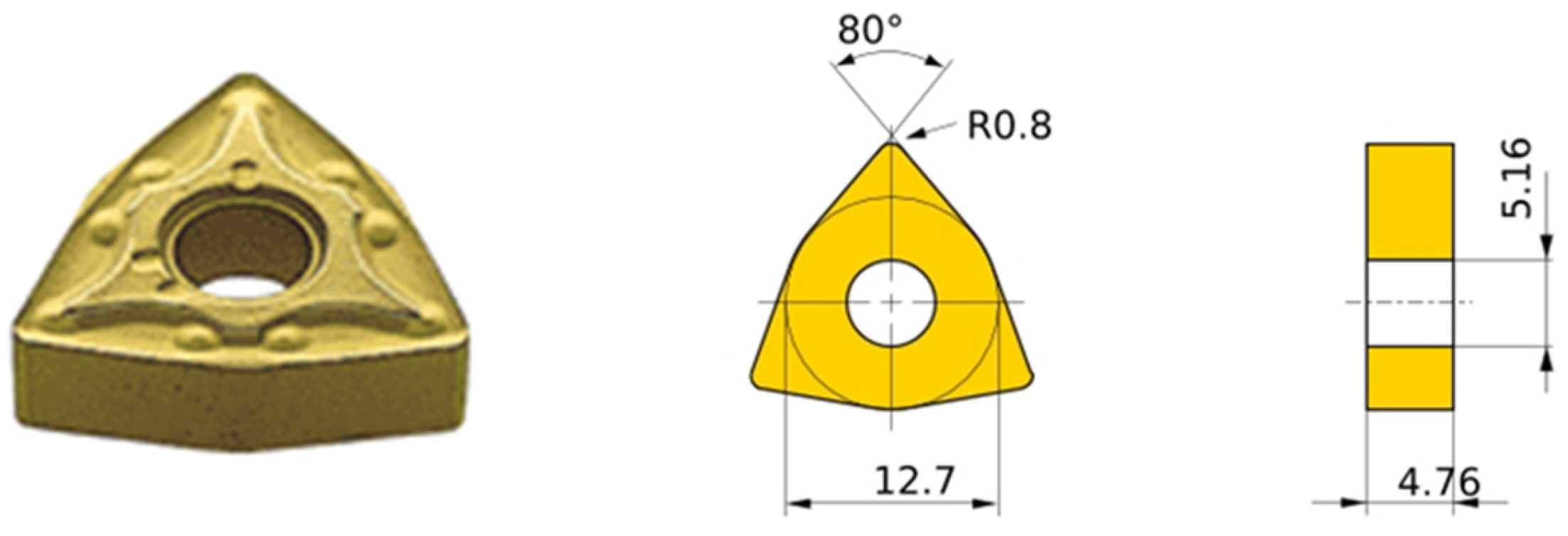
Figure 1 shows a machining insert WNMG080408-MA (dimensions are given in millimetres).

2.3. Reuse Cycle Methodology

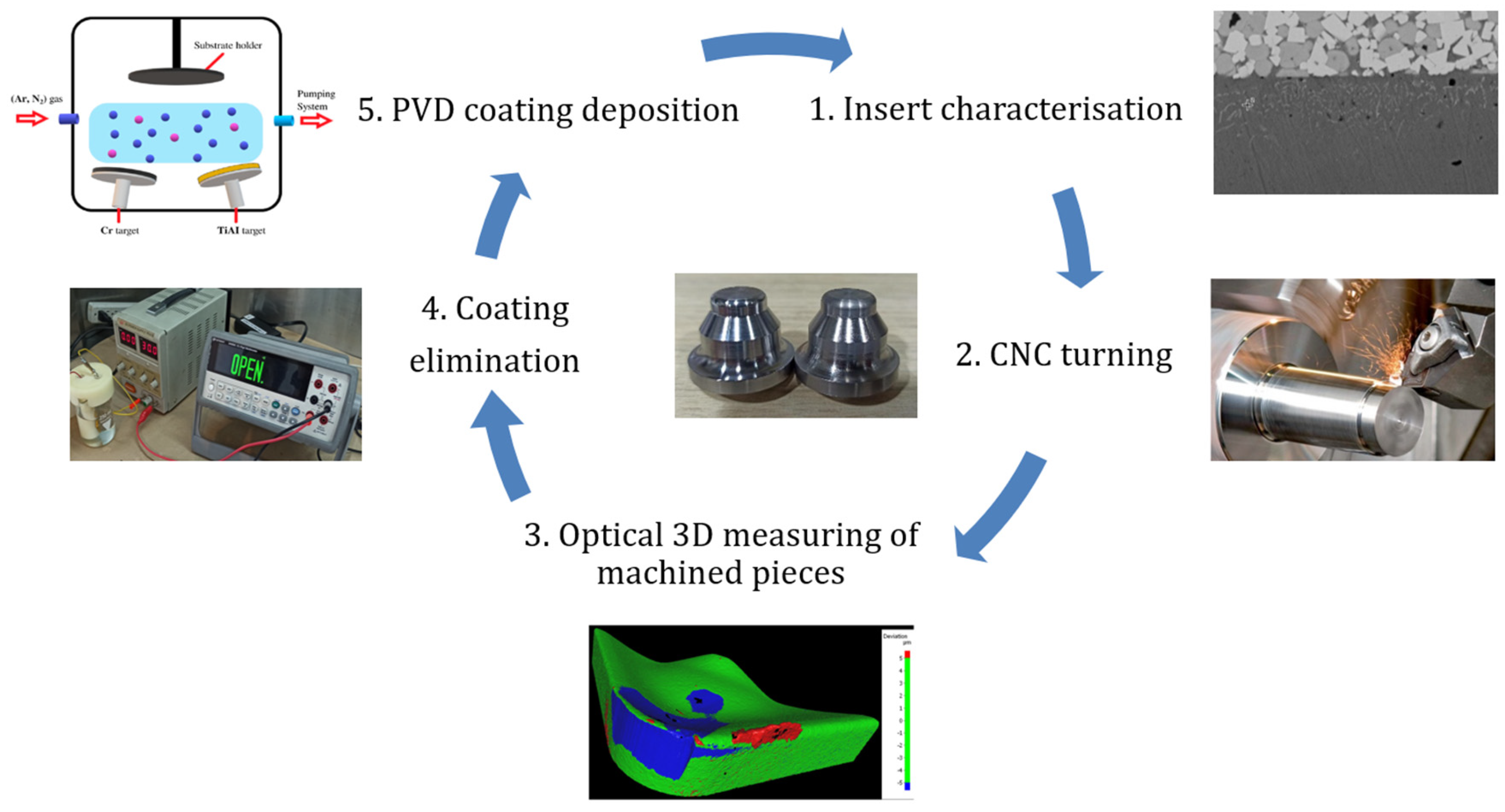
The reuse methodology is composed of 5 steps as follows: 1. insert characterization, 2. CNC turning, 3. optical 3D measuring of machined pieces, 4. coating elimination, and 5. PVD coating deposition. The overall reuse cycle is depicted in Figure 2. To assess the feasibility of reusing the carbide insert by stripping and re-coating, a single cutting edge was coated with four PVD systems: CrN, TiAlN, TiAlCrN, and TiAlCrSiN. For each coating chemistry, two cycles were performed on the same edge to determine the reproducibility of the process and the effect of that on the surface quality of the parts, the wear phenomena of the inserts.
In step 1, the coated insert is characterized by means of X-ray diffraction, scanning electron microscopy, and optical 3D metrology. The determination of the phases present in the coating was obtained using a PANalytical X’pert pro (Almelo, The Netherlands) with Ni-filtered Cu K radiation operating at 40 kV and 40 mA. The scanning range varied from 30° to 90° with a step size of 0.02° and a time per step of 1 s. The microstructure of the as-deposited machining inserts and the manufactured samples was examined using a PHENOM pro X scanning electron microscope (SEM) (Eindhoven, The Netherlands) equipped with energy-dispersive spectroscopy (EDS) analysis. Thickness measurements for all analyzed coatings were conducted using a Dektak 150 profilometer (Tucson, AZ, USA) yielding a consistent thickness of approximately 1.2 µm across all coatings.
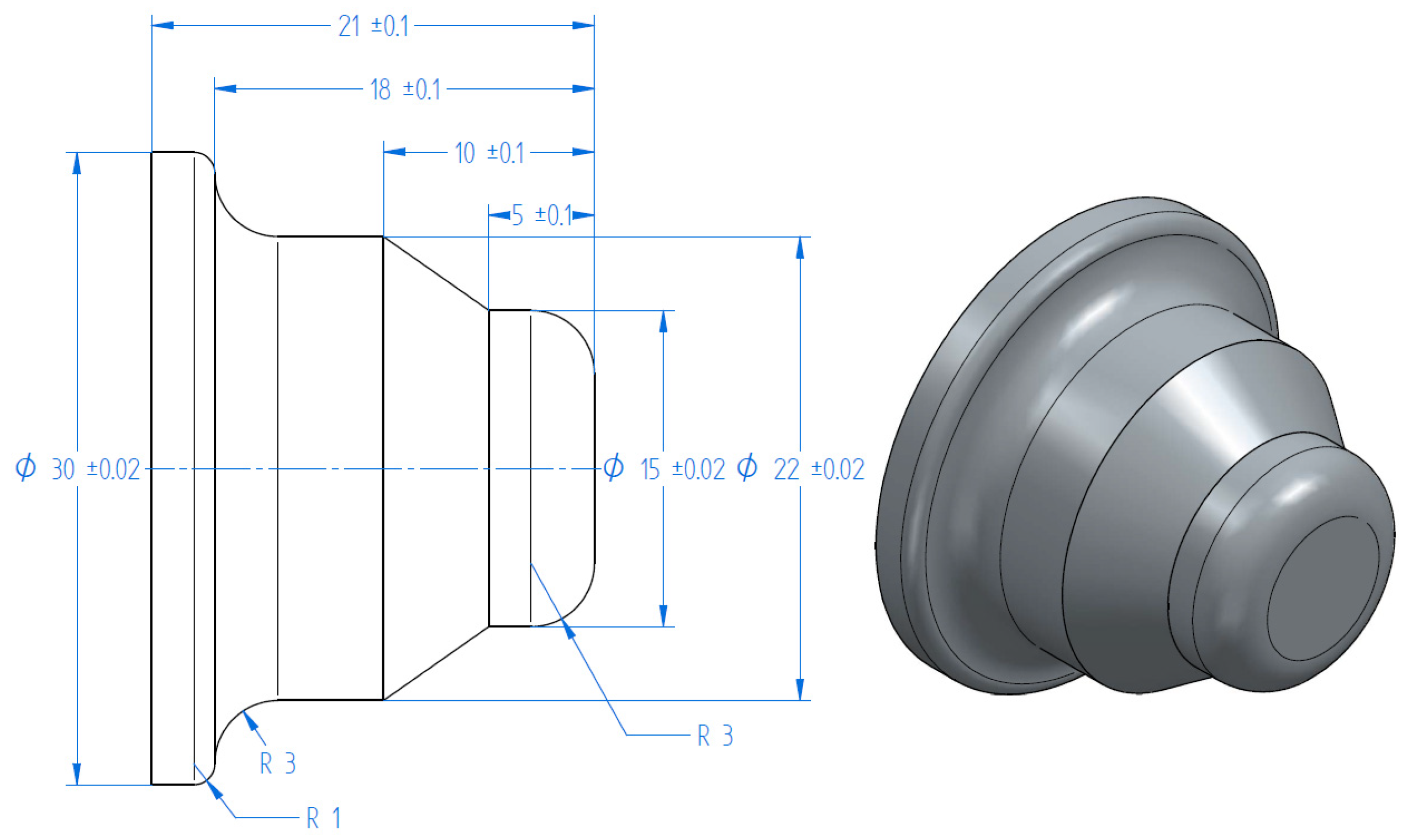
Step 2 involves CNC turning of six pieces for each reuse cycle (Figure 3). Turning tests were carried out using coated WNMG 080408 inserts mounted in a Korloy WWLNR-2020K08 (Cheongju, Republic of Korea) tool turning holder attached to a CNC CK40 horizontal machining center (Tengzhou, China) with a 1 m center-to-center distance, equipped with a 12-station turret. As a coolant, a soluble oil was used with a mixture of 1 part oil to 20 parts water. The turning parameters for 4340 steel are shown in Table 2.
In step 3, the 3D optical surface measurement system (InfiniteFocus G5, Alicona Imaging GmbH, Raaba, Austria) based on focus variation was used to characterize cutting insert wear and the surface roughness of machined workpieces. The system provides high-resolution areal topography with a maximum vertical resolution of 20 nm, enabling precise quantification of micro-scale wear features and surface texture.
Coating removal in step 4 consists of electrolytic stripping followed by surface preparation using conventional sandblasting. The potentiostatic technique was performed using a TECH TPD 5130 power supply, to which the electrolytic cell and a Keysight 34450 A multimeter were connected in series. The multimeter was used to measure the reaction current, which was recorded using BenchVue® software Version 2019.1. The current range was set to automatic by default; however, for measurements at 5 and 10 V, the 100 mA input was used, whereas for measurements at 20 and 30 V, the 10 A input was required. Subsequently, residual particles were removed by sandblasting in a CMV machine using aluminum oxide (Al2O3) abrasive with a 60-mesh (0.25 mm) particle size at a pressure of 45 psi for 3 min.
Finally, the coatings were manufactured at the laboratory level using a DC magnetron sputtering (step 5) where 270 W was applied to a TiAl target and an RF power between 70 and 170 W was applied to a metallic Cr target. Both targets had a diameter of 4 in and a purity of 99.99%. The substrate–target distance was maintained at 10 cm, with a confocal arrangement at an angle of 60°. During deposition, the argon and nitrogen flow rates were set to 4 and 14 sccm, respectively. The base pressure was 1.08 × 10⁻³ Pa, and the substrate temperature was held at 200 °C. The working pressure was kept constant at 0.4 Pa. After 50 min of sputtering, the coated samples were allowed to cool to room temperature. Silicon pieces were positioned equidistant on the Cr target to promote the incorporation of Si during co-sputtering, as described in our previous work [10]. In that study, the TiAlCrN-based coatings were chemically analyzed in greater detail, confirming the formation of Ti-, Al-, Cr-, and Si-containing nitride species.
Under the reactive sputtering conditions used in this work, the formation of the different nitride coatings can be interpreted from the target configuration, the Ar/N2 atmosphere, and the structural evidence provided by XRD and SEM. In the binary system, CrN is formed through the reaction of sputtered Cr species with activated nitrogen, yielding a CrN-based structure consistent with previous studies on magnetron-sputtered chromium nitride coatings [24,37]. In TiAlN, the simultaneous incorporation of Ti and Al promotes the formation of a metastable cubic nitride phase when the Al content remains within the solubility range of the B1 structure. It is widely used on carbide substrates because of its good adhesion and wear-related performance under demanding conditions [38]. For TiAlCrN, the additional incorporation of Cr into the TiAlN-based nitride system has been associated with improved oxidation resistance and thermal stability, while also influencing the structural evolution of the coating [39]. Finally, in TiAlCrSiN, the incorporation of Si through pieces mounted on the Cr target is expected to promote grain refinement and the development of a nanostructured morphology, in agreement with our previous work on TiAlCrN-based coatings prepared by co-sputtering [32]. Hence, the deposition route together with the XRD and SEM results supports the successful formation of the four nitride coatings.

3. Results

3.1. Coating Characterization

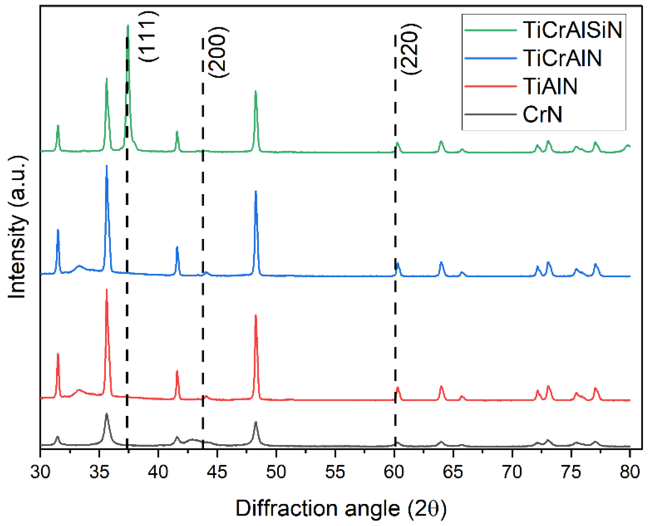
In Figure 4, X-ray diffraction patterns for all the coatings are depicted. The peaks related to the coatings are identified for their respective planes; the others correspond to the substrate, WC-Co.
The XRD patterns of the CrN, TiAlN, TiAlCrN, and TiAlCrSiN coatings (Figure 4) show diffraction peaks that correspond to a single-phase FCC NaCl-type structure. The most intense reflections are located at 2θ ≈ 37.4°, 43.7°, and 60.4°, corresponding to the (111), (200), and (220) planes, respectively, confirming that all coatings grow in the typical B1 nitride structure. Compared with the binary CrN reference, the main peaks of the ternary and quaternary coatings are slightly shifted in position, which indicates substitutional incorporation of Ti, Al, and Si into the CrN lattice.
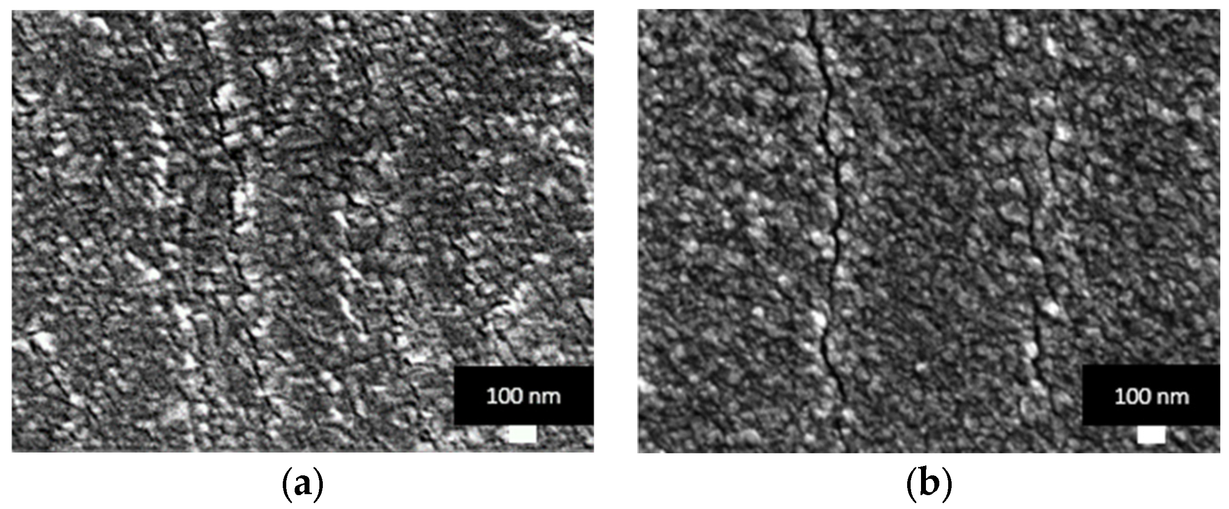
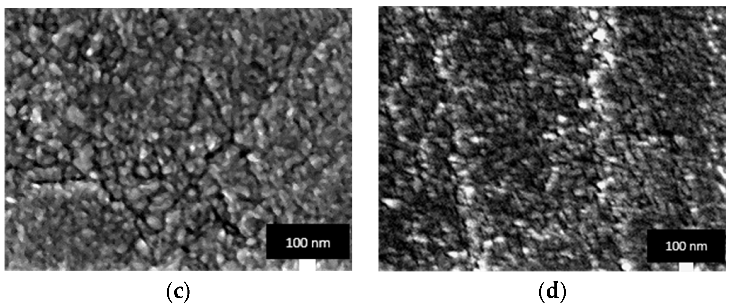
Figure 5 depicts the SEM images at 50kX magnification for the four coatings under study.
The SEM micrographs evidence that all coatings present a dense, nanostructured morphology characteristic of PVD-deposited transition metal nitride coatings. The surface is composed of tightly packed grains with sizes on the order of a few tens of nanometers, with no evidence of pores or discontinuities. This fine granular structure is consistent with the broadened diffraction peaks observed in the XRD patterns, which suggest the presence of small crystallite size and/or lattice strain in the coatings.
CrN, TiAlN, and TiAlCrN, as shown in Figure 5a, b, and c, respectively, show a homogeneous morphology, with subtle contrast variations that can be associated with grain boundaries and local compositional or strain fluctuations. Nevertheless, TiAlN and TiAlCrN exhibit elongated bright–dark features, which can be interpreted as surface cracks. These features are typical of hard nitride coatings deposited under high compressive stress and may originate from the relaxation of residual stresses during cooling or from thermal substrate–coating mismatch [40,41]. In addition, the limited strain accommodation of these hard nitride layers may promote the formation of localized surface fissures when internal stresses exceed the elastic tolerance of the coating. Their shallow and discontinuous appearance suggests that they are confined surface features rather than evidence of extensive delamination or catastrophic coating failure. TiAlCrSiN (Figure 5d) presents a slightly coarser but still nanometric surface; however, HRTEM is necessary to confirm nanostructured characteristics. Finally, no macroparticles, droplets, or large pinholes were detected, which indicates that the deposition conditions promoted a dense and relatively defect-free growth, which is beneficial for mechanical and tribological performance.

3.2. Machining Insert Reuse Behavior

The tool inserts were used to machine workpieces, as shown in Table 2. For each of the two cycles, the surface roughness of the six manufactured workpieces was evaluated, and the insert wear behavior was analyzed in terms of volume loss or gain and the corresponding morphological changes.
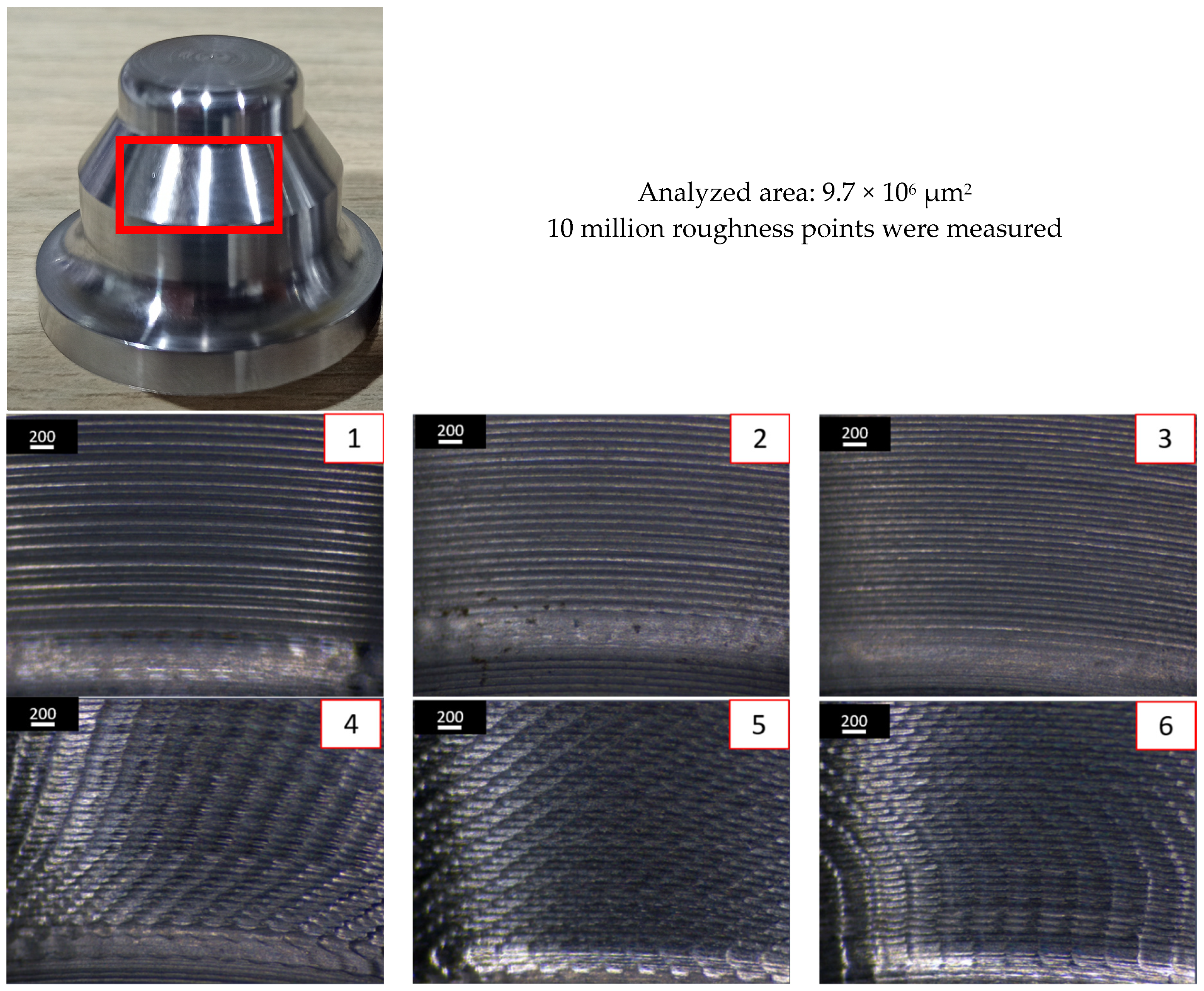
In Figure 6, the machined workpiece and the region where the roughness measurements were performed, as well as optical images of the six machined parts. These images are representative of the behavior of the four coatings under study.
The optical micrographs of the six machined workpieces, shown in Figure 5, reveal a clear evolution of the surface topography as the tool wear progresses. In parts 1–3, the turned surfaces exhibit well-defined and nearly equidistant feed marks along the cutting direction. The grooves are relatively shallow and continuous, indicating a stable cutting process with a still-sharp edge.
In contrast, the surfaces of machined parts 4–6 depict a markedly different texture. The regular turning marks are progressively replaced by a pronounced “fish-scale” or cross-hatched pattern, with overlapping scallops and brighter smeared regions. This change is characteristic of increased flank and rake-face wear, including edge rounding and possible built-up edge formation [42]. Under these conditions, the tool no longer shears the material cleanly; instead, it promotes ploughing and local plastic deformation, which leads to higher roughness [22]. The observed trend in surface texture is, therefore, consistent with the expected degradation of surface finish as the tool wears, in agreement with the roughness measurements discussed in the following section.
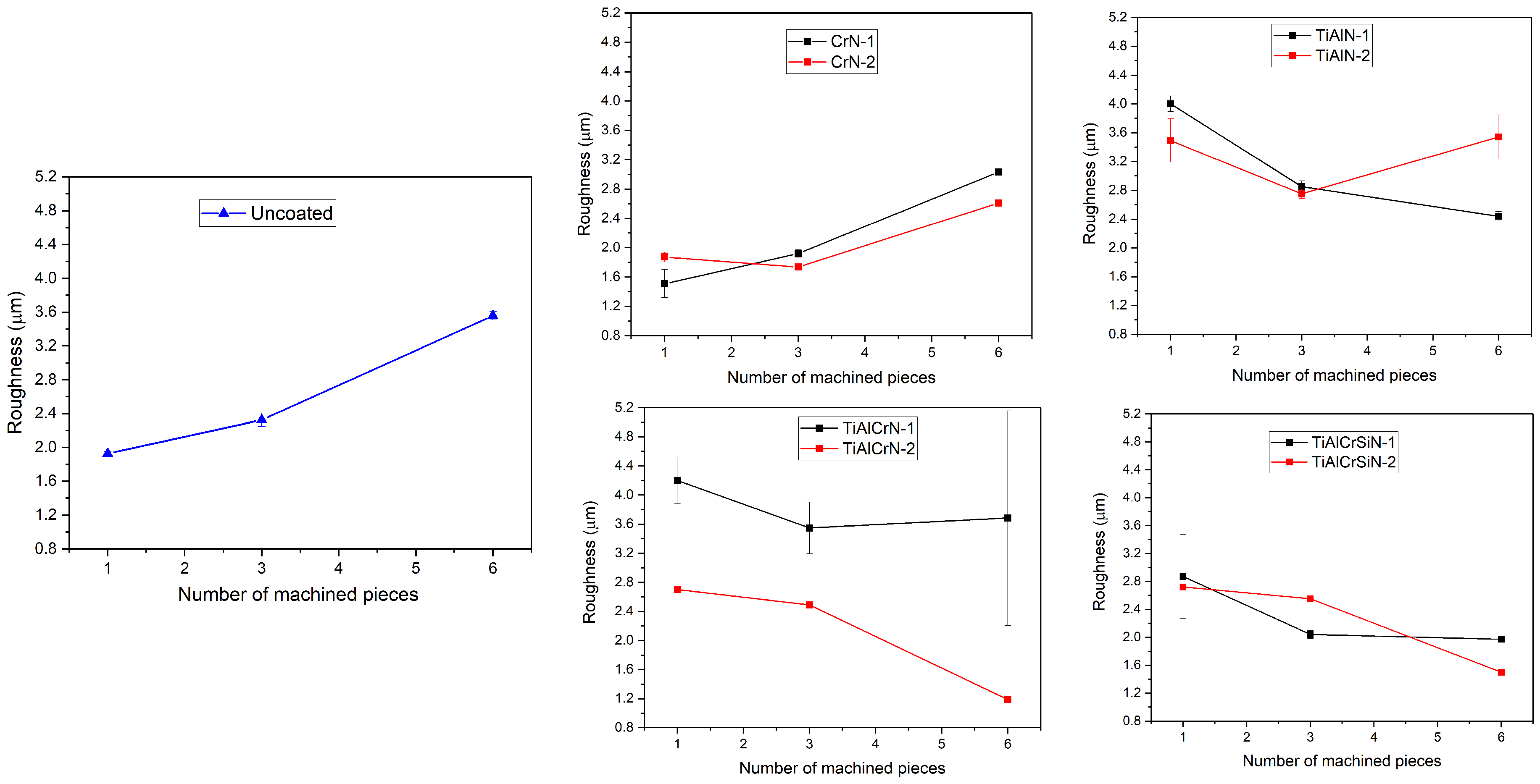
The surface roughness, obtained using a focal variation microscope, of each machined part was measured along the circumferential direction, and the mean Ra value was calculated from 10 million points; the corresponding trends are labeled “Coating–1” in Figure 7. In this first cycle, the freshly coated insert was used to turn six identical workpieces under fixed cutting conditions (Table 2). Then, after completing the six parts, the coating was completely removed by electrolytic stripping, and the same coating was re-deposited using identical PVD parameters. The re-coated insert was then used to machine another series of six workpieces, and the roughness was measured in the same way. These second-cycle results are labeled “coating–2”.
The roughness evolution for the uncoated insert, which serves as a reference for the four coated conditions, is depicted in Figure 7. Ra increases from ~1.8 µm on the first workpiece to ~3.5 µm on the sixth, evidencing rapid edge wear and severe tool damage. Due to this pronounced deterioration, a second machining cycle was not performed for the uncoated insert. For the binary CrN coating, the roughness increases with the number of machined pieces in both cycles, rising from ~1.5–1.7 µm on the first piece to about 2.5–3.0 µm on the sixth piece. The fact that CrN-2 follows a similar trend and magnitude to CrN-1 indicates that the coating can be reapplied without a drastic loss in performance. This monotonic increase reflects progressive flank wear and edge rounding of the insert.
A comparison of the roughness trends between the first and second cycles also reveals that the effect of re-coating depends strongly on coating chemistry. CrN shows nearly parallel trends in both cycles, indicating that the re-deposited layer largely reproduces the original cutting response, although without a substantial improvement in surface finish. TiAlN behaves differently, since the second cycle does not preserve the behavior observed initially and instead shows a renewed roughness increase toward the final workpieces, which is consistent with unstable adhesion and repeated built-up edge detachment. By contrast, TiAlCrN and TiAlCrSiN exhibit a more favorable evolution after re-coating, particularly TiAlCrN, whose second cycle yields markedly lower roughness values. This suggests that multicomponent coatings not only retain functionality after stripping and re-deposition but also develop a more stable tribological response during repeated use.
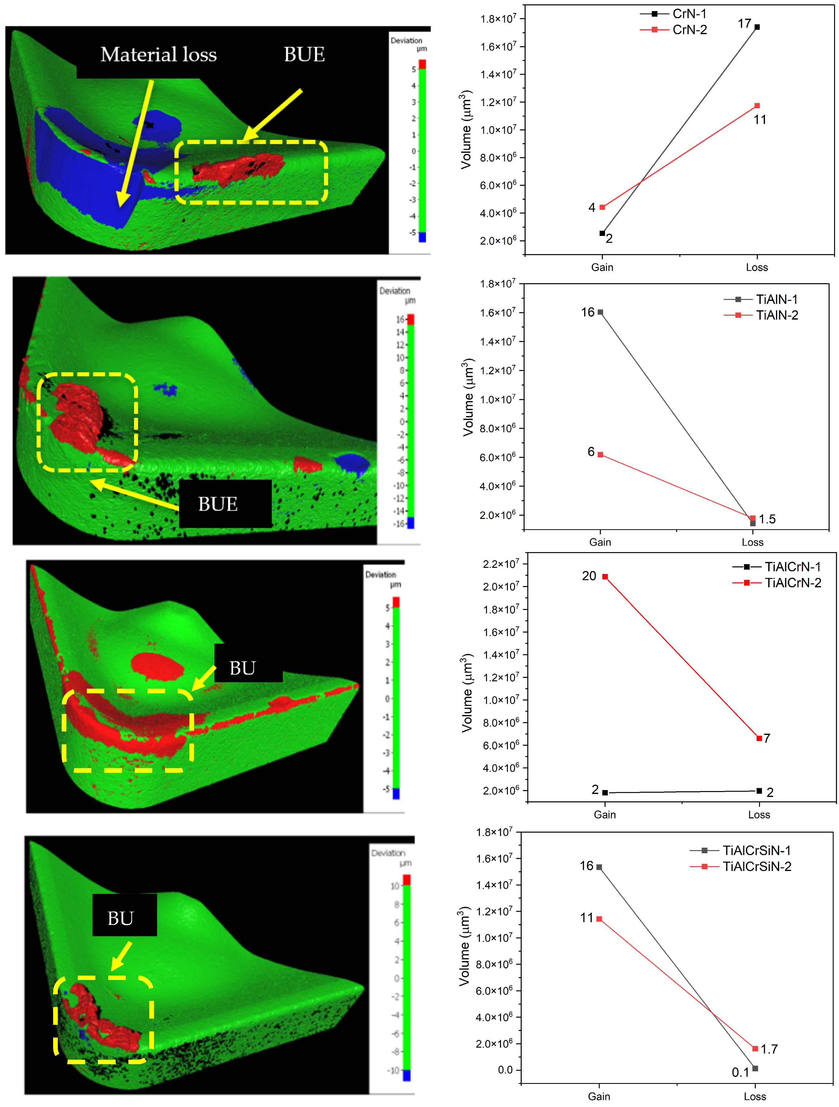
The effect in the tool insert is observed in Figure 7. In the CrN insert, a large blue volume of 17 × 107 μm3 and 11 × 107 μm3 for one and two cycles, respectively, on the rake face near the cutting edge reveals pronounced material removal, consistent with crater wear [43,44]. The red band along the depth-of-cut line on the flank face is characteristic of notch wear and material transfer promoted by mechanical loads of continuous turning, which favors adhesion to the steel and results in built-up material, detachment, and progressive coating loss.
The 3D deviation maps also provide complementary information that cannot be inferred from roughness alone. In particular, the distinction between blue regions (material loss) and red regions (material adhesion) makes it possible to differentiate coatings dominated by coating removal from those governed mainly by transfer layer formation. CrN is characterized by extensive blue regions, indicating dominant coating loss and severe crater/flank damage, whereas TiAlN shows a mixed response in which large adhered volumes coexist with localized material removal, consistent with cyclic BUE formation and detachment. In contrast, TiAlCrN and especially TiAlCrSiN are dominated by more stable adhered regions with comparatively limited blue zones, indicating that the wear process becomes increasingly controlled by protective transfer layers rather than by rapid coating degradation. This progressive shift from material loss to more stable adhesion is consistent with the improved roughness response observed for the multicomponent coatings.
In the first cycle of TiAlN, the roughness decreases from ~4.0 µm to ~2.4 µm, suggesting a running-in effect: the initially rough coated edge is smoothed by the first passes, after which a stable and finer surface is produced. In the second cycle (TiAlN-2), Ra decreases up to the third piece (see Figure 5) but increases again for the sixth piece, which can be attributed to severe wear or adhesion in the reused insert. Consequently, large material adhesion (16 × 107 μm3 and 6 × 107 μm3 for cycle 1 and 2, respectively) on the rake and flank faces indicates extensive built-up edge (BUE) and built-up layer (BUL), with only localized blue regions of material loss. It is known that Al content increases hot hardness and promotes the formation of protective Al-rich oxides, which delay crater wear compared with CrN [14,45]. However, TiAlN still exhibits chemical affinity with the workpiece, causing adhesion–detachment cycles in which BUE fragments tear away small portions of the coating, producing the mixed red/blue pattern.
For the quaternary TiAlCrN coating, surface roughness in the first cycle remains high and nearly constant (~3.5–4.0 µm; Figure 7), indicating stable but moderate surface finish quality. In contrast, the second cycle (TiAlCrN-2) shows a pronounced reduction in Ra (~2.7 to ~1.0 µm), indicating that the stripping and re-coating cycle results in finer surfaces. Thus, in Figure 7, the wear map is dominated by a continuous red volume (20 × 107 μm3 in the second cycle) related to material adhesion along the depth-of-cut zone and a central red patch, with limited blue zones. This suggests that wear is governed mainly by stable adhesive layers and mild abrasion, rather than severe coating removal [21,43]. The addition of Cr to TiAlN improves toughness and oxidation resistance, reducing crack propagation and crater formation. As a result, the adhered layer acts partially as a protective tribofilm, leading to material accumulation on the flank and rake faces, while the underlying nanostructured coating remains largely intact after machining 12 parts [46,47].
The most complex coating, TiAlCrSiN, shows the best performance. In both cycles, roughness decreases with the number of machined parts, reaching ~1.3–1.6 µm on the sixth piece—the lowest values among all coatings. The similar downward trends for TiAlCrSiN-1 and TiAlCrSiN-2 confirm that stripping and re-coating do not penalize surface finish and may even slightly enhance cutting performance. This is consistent with the wear maps in Figure 8, where TiAlCrSiN exhibits the smallest adhered zone (~14 × 107 µm3) and limited material loss (~1.7 × 107 µm3). The superior behavior is attributed to the fine Al–Si-induced nanocrystalline/nanocomposite structure, which provides high hardness and thermal stability, while Cr improves oxidation resistance and toughness [10].
Overall, the comparison among CrN, TiAlN, TiAlCrN, and TiAlCrSiN reveals a clear relationship between coating composition, microstructural features, and wear-related performance. Although all coatings exhibited a B1-type nitride structure, the peak shifts observed from CrN to the ternary and quaternary systems suggest compositional modification of the lattice by Ti, Al, Cr, and Si incorporation. The binary CrN coating showed the least favorable behavior, with progressive roughness increase and the largest material loss volumes, indicating limited resistance to crater and flank wear. TiAlN improved thermal stability relative to CrN, but its behavior was still strongly influenced by adhesion–detachment phenomena and built-up edge formation. In contrast, the incorporation of Cr in TiAlCrN promoted more stable adhesive layers, lower effective coating damage, and improved surface finish after re-coating. The best overall response was obtained for TiAlCrSiN, whose more complex composition and Si-assisted nanostructural refinement were associated with the lowest roughness values and the smallest wear volumes. These results indicate that the progressive increase in alloying complexity and Si-assisted grain refinement enhances the functional performance of the coatings by stabilizing the tribological response during turning and supporting their suitability for repeated reuse cycles.

3.3. SEM Analysis of Worn Inserts

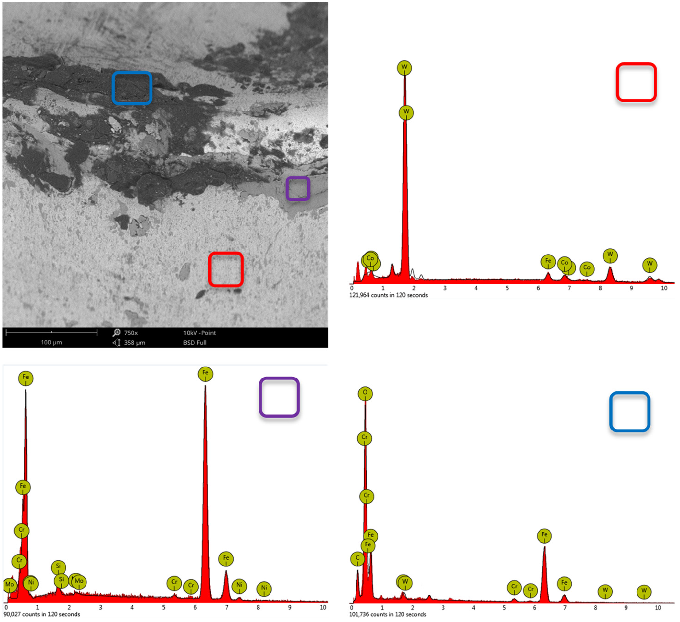
The following images present SEM micrographs of the rake and flank faces after machining 12 workpieces for each coating. These observations complement the 3D optical deviation maps shown in Figure 8 by revealing the underlying microscale wear mechanisms and their dependence on coating chemistry. The EDS analysis presented here was restricted to specific surface regions of the worn inserts. Consequently, the elemental distribution across the coating thickness and transferred layers could not be resolved by line-scan profiling. Figure 9 depicts the SEM image and semiquantitative analysis of the CrN-insert of the second cycle of reuse.
The flank wear exhibits a bright area where the coating has been entirely removed, corresponding to the WC–Co substrate, consistent with the blue zones quantified via the 3D optical technique (Figure 8). EDS analysis in this zone reveals W and Co signals and residual Cr and N as main elements, confirming crater and flank wear with local delamination of the coating. Along the cutting edge, finely spaced grooves oriented in the chip-flow direction and embedded fragments indicate abrasive action of workpiece AISI 4340 chips and debris, superimposed on adhesive wear. The presence of micro-cracks at the coating/substrate interface suggests that the limited hot hardness and oxidation resistance of CrN promote crack initiation and propagation, thus causing coating delamination under cyclic thermo-mechanical loading.
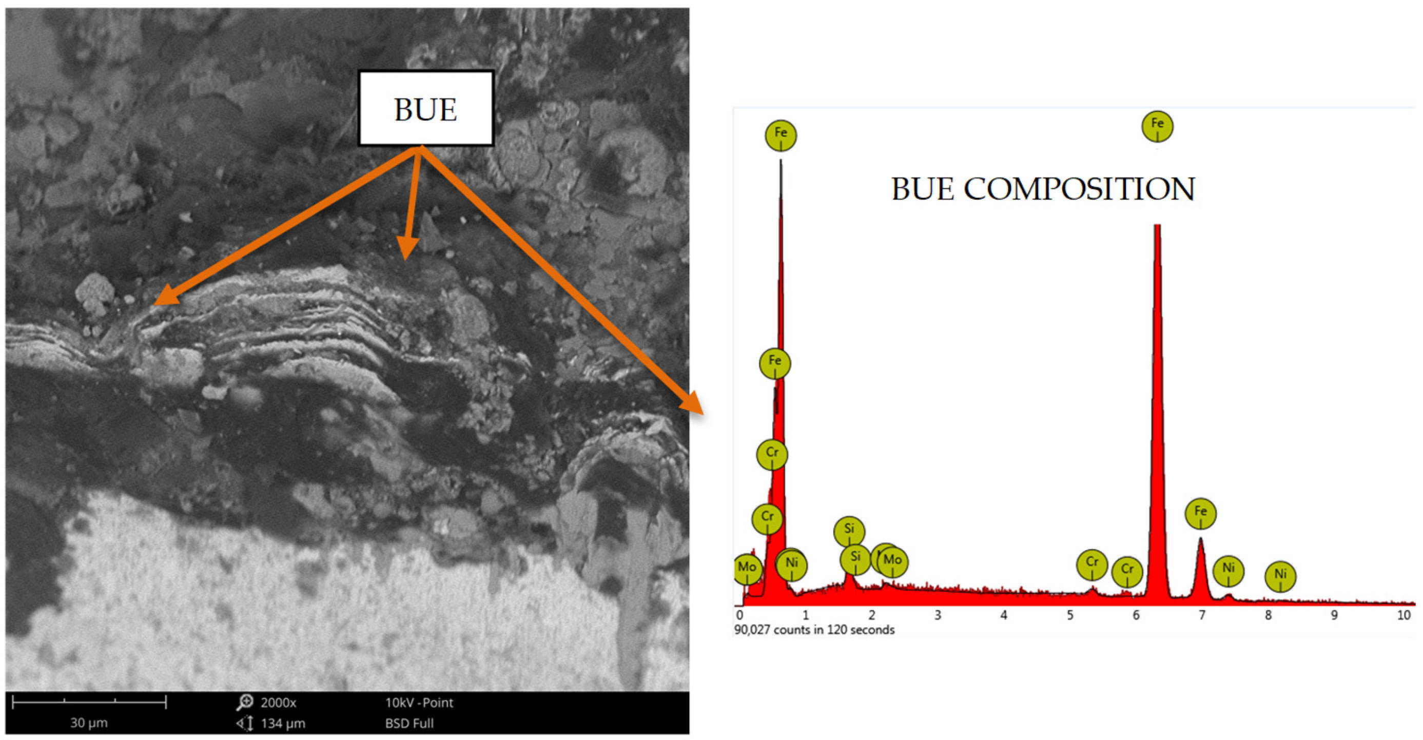
For the TiAlN coating (Figure 10), the dominant wear mechanism in the rake face and cutting-edge regions is BUE. BUE presents a compact morphology with evidence of repeated growth–detachment events.
EDS spectra of this region show noticeable Fe, Cr, and Mo peaks and minor contributions from Ti and Al, confirming that the adhered material originates from the AISI 4340 workpiece. This chemical affinity between TiAlN and the steel promotes adhesion at the chip–tool interface. When BUE fragments are detached, they may pull away thin portions of the coating or leave behind smeared layers, resulting in the mixed red/blue pattern observed in Figure 8 and the increase in roughness at the end of the second cycle. Shallow craters and eroded regions are observable beneath BUE, suggesting that adhesive and abrasive mechanisms operate simultaneously, with crater wear being influenced more by chip–tool interaction than by direct diffusion into the WC–Co substrate.
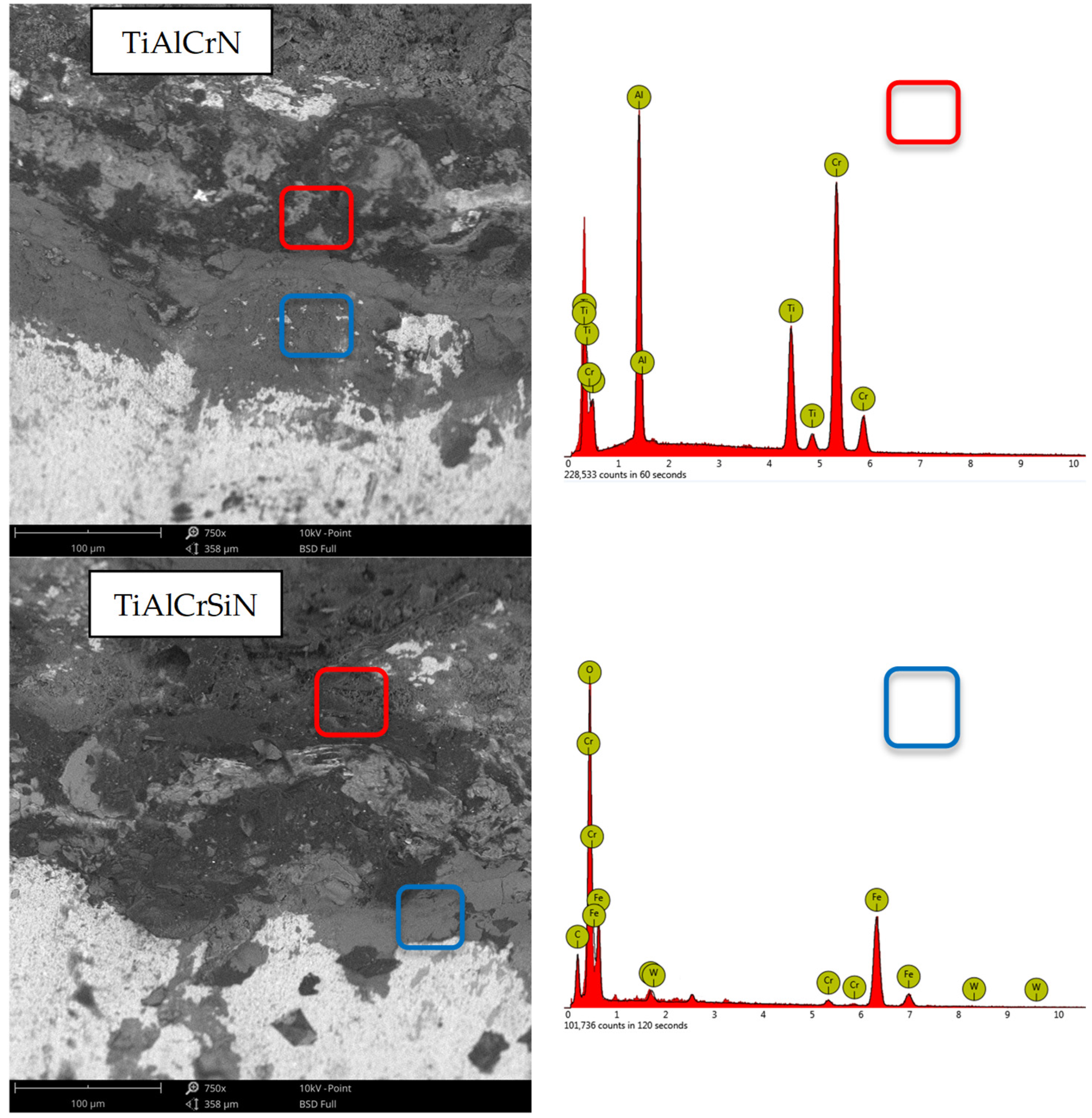
The worn edges of TiAlCrN and TiAlCrSiN are grouped in Figure 11 due to their similar morphology. In both coatings, the cutting edge remains continuous, with no large-scale delamination or deep craters.
A continuous adhered layer with a BUE formation tendency is formed along the rake and flank faces, aligning with the predominance of the red region (material adhesion) and the restricted blue material loss regions, as observed in Figure 8. The EDS analyses show the coexistence of Fe-rich tribofilms with Ti, Al, Cr, and W, suggesting the formation of a mixed transfer film that acts as a solid lubricant that enhances the turning operations [26,27,28,29]. Localized micro-cracks and minor chipping are evident, indicating that the improved toughness and oxidation resistance provided by chromium, along with silicon-induced grain refinement in TiAlCrSiN, limit diffusion-driven crater wear [10,46,47].

4. Conclusions

A five-step methodology combining XRD/SEM characterization, CNC turning, 3D optical profilometry, electrolytic stripping, and PVD re-deposition was successfully implemented on the same cutting edge of WC–Co inserts. The procedure enabled at least one complete reuse cycle per coating without damaging the substrate, demonstrating the technical feasibility of controlled insert reuse.
The uncoated WC–Co insert showed fast deterioration, with Ra increased from ~1.8 to ~3.5 µm after machining of six parts, and severe edge damage prevented a second cycle. This condition establishes a baseline and highlights the protective role of PVD nitride coatings in turning AISI 4340.
CrN produced a monotonic increase in roughness (from ~1.5–1.7 to 2.5–3.0 µm) in both cycles and large material loss volumes (≈17 × 107 and 11 × 107 µm3), dominated by crater and flank wear. TiAlN exhibited an initial running-in behavior in the first cycle, but roughness increased again in the second cycle due to BUE formation, with large adhesion volumes (≈16 × 107 and 6 × 107 µm3). TiAlCrN maintained relatively high but stable roughness in the first cycle, whereas the second cycle showed a marked improvement (≈2.7 to 1.0 µm), associated with large adhesive volumes (≈20 × 107 µm3) and limited material loss. TiAlCrSiN achieved the best performance, with roughness decreasing to ~1.3–1.6 µm in both cycles and the lowest wear volumes (≈14 × 107 µm3 adhesion and ≈1.7 × 107 µm3 loss).
SEM/EDS of worn inserts confirmed that CrN is governed by combined abrasive and adhesive wear with coating delamination and exposure of the WC–Co substrate. TiAlN is dominated by massive BUE, leading to local crater formation beneath adhered layers. TiAlCrN and TiAlCrSiN develop thin, continuous Fe-rich tribofilms with a BUE formation with slight micro-cracking and chipping. The progressive alloying from CrN to TiAlCrSiN, together with Si-induced grain refinement, enhances hardness, toughness, and oxidation resistance, thereby stabilizing adhesive layers and reducing notching and crater wear.
The comparison between the first and second cycles shows that stripping and PVD re-coating do not penalize tool performance for TiAlCrN and TiAlCrSiN; in fact, TiAlCrN exhibited improved surface finish after reuse. This indicates that multicomponent nanostructured coatings can tolerate at least one reuse cycle without loss of functionality, making them promising candidates for circular strategies aimed at extending insert life and reducing the consumption of critical Co–W resources.
For future work, additional reuse cycles, a broader range of cutting parameters, and tool-life criteria, as well as residual stress and diffusion analyses, are needed to further quantify the long-term stability of reused coated inserts and strengthen the case for their industrial implementation.

Author Contributions

Conceptualization, L.C.A. and E.E.A.; methodology, L.C.A. and F.F.V.; validation, L.C.A., F.F.V. and E.E.A.; formal analysis, L.C.A.; investigation, L.C.A. and F.F.V.; resources, C.M.M. and J.J.O.; data curation, F.F.V.; writing—original draft preparation, L.C.A. and E.E.A.; writing—review and editing, J.J.O. and L.C.A.; visualization, F.F.V.; supervision, J.J.O.; project administration, C.M.M. and J.J.O.; funding acquisition, C.M.M. All authors have read and agreed to the published version of the manuscript.

Funding

This research was funded by MINCIENCIAS; the project is identified by the Code 1109-808-63425, Contract: 202-2019.

Institutional Review Board Statement

Not applicable.

Informed Consent Statement

Not applicable.

Data Availability Statement

The original contributions presented in this study are included in the article. Further inquiries can be directed to the corresponding authors.

Conflicts of Interest

The authors declare no conflicts of interest.

References

  1. Khan, P.L.; Bhivsane, S.V. Experimental Analysis and Investigation of Machining Parameters in Finish Hard Turning of AISI 4340 Steel. Procedia Manuf. 2018, 20, 265–270. [Google Scholar] [CrossRef]
  2. Das, A.; Mukhopadhyay, A.; Patel, S.K.; Biswal, B.B. Comparative Assessment on Machinability Aspects of AISI 4340 Alloy Steel Using Uncoated Carbide and Coated Cermet Inserts During Hard Turning. Arab. J. Sci. Eng. 2016, 41, 4531–4552. [Google Scholar] [CrossRef]
  3. Abbas, A.T.; Al-Abduljabbar, A.A.; Alnaser, I.A.; Aly, M.F.; Abdelgaliel, I.H.; Elkaseer, A. A Closer Look at Precision Hard Turning of AISI4340: Multi-Objective Optimization for Simultaneous Low Surface Roughness and High Productivity. Materials 2022, 15, 2106. [Google Scholar] [CrossRef]
  4. Deng, Y.; Chen, W.; Li, B.; Wang, C.; Kuang, T.; Li, Y. Physical Vapor Deposition Technology for Coated Cutting Tools: A Review. Ceram. Int. 2020, 46, 18373–18390. [Google Scholar] [CrossRef]
  5. Das, K.C.; Tripathy, N.; Ghosh, S.P.; Sharma, P.; Singhal, R.; Kar, J.P. Microstructural, Surface and Interface Properties of Zirconium Doped HfO2 Thin Films Grown by RF Co-Sputtering Technique. Vacuum 2017, 143, 288–293. [Google Scholar] [CrossRef]
  6. Su, Y.L.; Yao, S.H.; Wei, C.S.; Wu, C.T.; Kao, W.H. Evaluation on the Wear, Tension and Fatigue Behavior of Various PVD Coated Materials. Mater. Lett. 1998, 35, 255–260. [Google Scholar] [CrossRef]
  7. Agrawal, A.; Goel, S.; Rashid, W.B.; Price, M. Prediction of Surface Roughness during Hard Turning of AISI 4340 Steel (69 HRC). Appl. Soft Comput. 2015, 30, 279–286. [Google Scholar] [CrossRef]
  8. Wu, L.; Qiu, L.; Du, Y.; Zeng, F.; Lu, Q.; Tan, Z.; Yin, L.; Chen, L.; Zhu, J. Structure and Mechanical Properties of PVD and CVD TiAlSiN Coatings Deposited on Cemented Carbide. Crystals 2021, 11, 598. [Google Scholar] [CrossRef]
  9. Krbata, M.; Eckert, M.; Majerik, J.; Barenyi, I. Wear Behaviour of High Strength Tool Steel 90MnCrV8 in Contact with Si3N4. Metals 2020, 10, 756. [Google Scholar] [CrossRef]
  10. Ardila, L.C.; Dueñas, R.; Orozco, G.; Olaya, J.J.; Ordoñez, A.F.; Moreno, C.M.; Pineda, Y. Influence of Si Addition on the Chemical and Tribological Performance of TiAlCrN Coating Deposited by Co-Sputtering. Crystals 2023, 13, 1666. [Google Scholar] [CrossRef]
  11. Stachowiak, G.; Batchelor, A.W. Engineering Tribology; Butterworth-Heinemann: Oxford, UK, 2013. [Google Scholar]
  12. Saraf, G.; Nirala, C.K. Experimental Investigation of Micro-Pillar Textured WC Inserts during Turning of Ti6Al4V under Various Cutting Fluid Strategies. J. Manuf. Process. 2024, 113, 61–75. [Google Scholar] [CrossRef]
  13. Saketi, S.; Östby, J.; Olsson, M. Influence of Tool Surface Topography on the Material Transfer Tendency and Tool Wear in the Turning of 316L Stainless Steel. Wear 2016, 368–369, 239–252. [Google Scholar] [CrossRef]
  14. Chen, Q.; Su, M.; Liang, D.; Zhang, Y.; Zhou, Q.; Zhang, E. Influence of N2 Flow Rate on the Microstructure, Mechanical, and Tribological Properties of Ti-Al-Cr-N Coating: Dry Milling Investigation on 6061 Aluminum Alloy. J. Mater. Eng. Perform. 2025, 34, 4303–4314. [Google Scholar] [CrossRef]
  15. Wang, J.; Liu, Z.; Wu, Y.; Wang, Q.; Shu, D. Cutting Performance and Tool Wear of AlCrN- and TiAlN-Coated Carbide Tools during Milling of Tantalum–Tungsten Alloy. Machines 2024, 12, 170. [Google Scholar] [CrossRef]
  16. Ramirez, C.; Idhil Ismail, A.; Gendarme, C.; Dehmas, M.; Aeby-Gautier, E.; Poulachon, G.; Rossi, F. Understanding the Diffusion Wear Mechanisms of WC-10%Co Carbide Tools during Dry Machining of Titanium Alloys. Wear 2017, 390–391, 61–70. [Google Scholar] [CrossRef]
  17. Chinchanikar, S.; Choudhury, S.K. Investigations on Machinability Aspects of Hardened AISI 4340 Steel at Different Levels of Hardness Using Coated Carbide Tools. Int. J. Refract. Met. Hard Mater. 2013, 38, 124–133. [Google Scholar] [CrossRef]
  18. Ginting, A.; Skein, R.; Cuaca, D.; Herdianto; Pieter; Masyithah, Z. The Characteristics of CVD- and PVD-Coated Carbide Tools in Hard Turning of AISI 4340. Measurement 2018, 129, 548–557. [Google Scholar] [CrossRef]
  19. Bag, R.; Panda, A.; Sahoo, A.K.; Kumar, R. Cutting Tools Characteristics and Coating Depositions for Hard Part Turning of AISI 4340 Martensitic Steel: A Review Study. Mater. Today Proc. 2020, 26, 2073–2078. [Google Scholar] [CrossRef]
  20. Coelho, R.T.; Ng, E.-G.; Elbestawi, M.A. Tool Wear When Turning Hardened AISI 4340 with Coated PCBN Tools Using Finishing Cutting Conditions. Int. J. Mach. Tools Manuf. 2007, 47, 263–272. [Google Scholar] [CrossRef]
  21. Wagri, N.K.; Jain, N.K.; Petare, A.; Das, S.R.; Tharwan, M.Y.; Alansari, A.; Alqahtani, B.; Fattouh, M.; Elsheikh, A. Investigation on the Performance of Coated Carbide Tool during Dry Turning of AISI 4340 Alloy Steel. Materials 2023, 16, 668. [Google Scholar] [CrossRef]
  22. Zheng, G.; Cheng, X.; Li, L.; Xu, R.; Tian, Y. Experimental Investigation of Cutting Force, Surface Roughness and Tool Wear in High-Speed Dry Milling of AISI 4340 Steel. J. Mech. Sci. Technol. 2019, 33, 341–349. [Google Scholar] [CrossRef]
  23. Hornik, J.; Rybníček, J.; Rund, M.; Hájková, P.; Anisimov, E.; Tondl, D. Evaluation of Properties of CrN PVD Coating for Functionally Graded Materials. In Proceedings of the METAL 2012—Conference Proceedings, 21st International Conference on Metallurgy and Materials, Brno, Czech Republic, 23–25 May 2012. [Google Scholar]
  24. Liu, C.; Bi, Q.; Ziegele, H.; Leyland, A.; Matthews, A. Structure and Corrosion Properties of PVD Cr–N Coatings. J. Vac. Sci. Technol. A 2002, 20, 772–780. [Google Scholar] [CrossRef]
  25. Xu, Y.; Chen, L.; Liu, Z.; Pei, F.; Du, Y. Influence of Ti on the Mechanical Properties, Thermal Stability and Oxidation Resistance of Al–Cr–N Coatings. Vacuum 2015, 120, 127–131. [Google Scholar] [CrossRef]
  26. Blinkov, I.V.; Volkhonskii, A.O.; Konyukhov, Y.V. Nanostructured Arc-PVD Coatings Based on Titanium and Chromium Nitrides. Russ. Metall. 2012, 2012, 599–605. [Google Scholar] [CrossRef]
  27. Vereschaka, A.; Tabakov, V.; Grigoriev, S.; Sitnikov, N.; Milovich, F.; Andreev, N.; Bublikov, J. Investigation of Wear Mechanisms for the Rake Face of a Cutting Tool with a Multilayer Composite Nanostructured Cr–CrN-(Ti,Cr,Al,Si)N Coating in High-Speed Steel Turning. Wear 2019, 438–439, 203069. [Google Scholar] [CrossRef]
  28. Bensouilah, H.; Aouici, H.; Meddour, I.; Yallese, M.A.; Mabrouki, T.; Girardin, F. Performance of Coated and Uncoated Mixed Ceramic Tools in Hard Turning Process. Measurement 2016, 82, 1–18. [Google Scholar] [CrossRef]
  29. Bobzin, K.; Bagcivan, N.; Brugnara, R.H.; Stalpers, L.; Klocke, F.; Arntz, K.; Ewering, M.T. Application of (Ti,Cr,Al,Si)N PVD Coatings in Hard Machining of PM High Speed Steel. In Proceedings of the 18th Plansee Seminar: International Conference on Refractory Metals and Hard Materials, Reutte, Austria, 3–7 June 2013. [Google Scholar]
  30. Liu, J.; Wang, Y.; Liu, G.; Hua, J.; Deng, X. Properties and Performance of TiAlSiN and AlCrN Monolayer and Multilayer Coatings for Turning Ti-6Al-4V. Coatings 2023, 13, 1229. [Google Scholar] [CrossRef]
  31. Roy, S.; Kumar, R.; Das, R.K.; Sahoo, A.K. A Comprehensive Review on Machinability Aspects in Hard Turning of AISI 4340 Steel. IOP Conf. Ser. Mater. Sci. Eng. 2018, 390, 012009. [Google Scholar] [CrossRef]
  32. Katiyar, P.K.; Randhawa, N.S. A Comprehensive Review on Recycling Methods for Cemented Tungsten Carbide Scraps Highlighting the Electrochemical Techniques. Int. J. Refract. Met. Hard Mater. 2020, 90, 105251. [Google Scholar] [CrossRef]
  33. Kumar, R.; Kariminejad, A.; Antonov, M.; Goljandin, D.; Klimczyk, P.; Hussainova, I. Progress in Sustainable Recycling and Circular Economy of Tungsten Carbide Hard Metal Scraps for Industry 5.0 and Onwards. Sustainability 2023, 15, 12249. [Google Scholar] [CrossRef]
  34. Rizzo, A.; Goel, S.; Luisa Grilli, M.; Iglesias, R.; Jaworska, L.; Lapkovskis, V.; Novak, P.; Postolnyi, B.O.; Valerini, D. The Critical Raw Materials in Cutting Tools for Machining Applications: A Review. Materials 2020, 13, 1377. [Google Scholar] [CrossRef]
  35. Mégret, A.; Vitry, V.; Delaunois, F. Study of the Processing of a Recycled WC–Co Powder: Can It Compete with Conventional WC–Co Powders? J. Sustain. Metall. 2021, 7, 448–458. [Google Scholar] [CrossRef]
  36. Pacini, A.; Lupi, F.; Rossi, A.; Seggiani, M.; Lanzetta, M. Direct Recycling of WC-Co Grinding Chip. Materials 2023, 16, 1347. [Google Scholar] [CrossRef] [PubMed]
  37. Kabir, M.S.; Munroe, P.; Zhou, Z.; Xie, Z. Structure and Mechanical Properties of Graded Cr/CrN/CrTiN Coatings Synthesized by Close Field Unbalanced Magnetron Sputtering. Surf. Coat. Technol. 2017, 309, 779–789. [Google Scholar] [CrossRef]
  38. Gong, M.; Chen, J.; Deng, X.; Wu, S. Sliding Wear Behavior of TiAlN and AlCrN Coatings on a Unique Cemented Carbide Substrate. Int. J. Refract. Met. Hard Mater. 2017, 69, 209–214. [Google Scholar] [CrossRef]
  39. Prieto-Novoa, G.; Vallejo, F.; Piamba, O.; Olaya, J.; Pineda, Y. Effects of Cr Concentration on the Structure and the Electrical and Optical Properties of Ti-Al-Cr-N Thin Films Prepared by Means of Reactive Co-Sputtering. Crystals 2022, 12, 1831. [Google Scholar] [CrossRef]
  40. Rashid, S.; Rossi, E.; Diplas, S.; Carvalho, P.A.; Pucicki, D.; Kuna, R.; Sebastiani, M. A Critical Comparison Among High-Resolution Methods for Spatially Resolved Nano-Scale Residual Stress Analysis in Nanostructured Coatings. Int. J. Mol. Sci. 2025, 26, 3296. [Google Scholar] [CrossRef]
  41. Ali, R.; Renzelli, M.; Khan, M.I.; Sebastiani, M.; Bemporad, E. Effects of Residual Stress Distribution on Interfacial Adhesion of Magnetron Sputtered AlN and AlN/Al Nanostructured Coatings on a (100) Silicon Substrate. Nanomaterials 2018, 8, 896. [Google Scholar] [CrossRef]
  42. Clavier, F.; Valiorgue, F.; Courbon, C.; Dumas, M.; Rech, J.; Robaeys, A.V.; Lefebvre, F.; Brosse, A.; Karaouni, H. Impact of Cutting Tool Wear on Residual Stresses Induced during Turning of a 15-5 PH Stainless Steel. Procedia CIRP 2020, 87, 107–112. [Google Scholar] [CrossRef]
  43. Muhamad, S.S.; Ghani, J.A.; Che Haron, C.H.; Yazid, H. Wear Mechanism of Multilayer Coated Carbide Cutting Tool in the Milling Process of AISI 4340 under Cryogenic Environment. Materials 2022, 15, 524. [Google Scholar] [CrossRef]
  44. Mamundi Azaath, L.; Mohan, E.; Natarajan, U. Effect of Rake Angle and Tool Geometry during Machining Process of AISI 4340 Steel in Finite Element Approach. Mater. Today Proc. 2021, 37, 3731–3736. [Google Scholar] [CrossRef]
  45. Zhang, X.D.; Chen, L.; Wang, G.Y.; Hu, C.; Du, J.W. Influence of CrAlN Layers on the Microstructure, Thermal Stability, Oxidation and Corrosion Resistance of AlN/CrAlN Multilayers. Mater. Charact. 2024, 214, 114051. [Google Scholar] [CrossRef]
  46. Gu, J.; Li, L.; Ai, M.; Xu, Y.; Xu, Y.; Li, G.; Deng, D.; Peng, H.; Luo, S.; Zhang, P. Improvement of Solid Particle Erosion and Corrosion Resistance Using TiAlSiN/Cr Multilayer Coatings. Surf. Coat. Technol. 2020, 402, 126270. [Google Scholar] [CrossRef]
  47. Sousa, V.F.C.; Silva, F.J.G.; Alexandre, R.; Fecheira, J.S.; Silva, F.P.N. Study of the Wear Behaviour of TiAlSiN and TiAlN PVD Coated Tools on Milling Operations of Pre-Hardened Tool Steel. Wear 2021, 476, 203695. [Google Scholar] [CrossRef]
Figure 1. WNMG080408-MA machining insert (Mitsubishi Materials, Costa Mesa, CA, USA, n.d.).
Coatings 16 00652 g001
Figure 2. Schema of the insert tool cycle reuse.
Coatings 16 00652 g002
Figure 3. Design and dimensions (mm) of the AISI 4340 steel part.
Coatings 16 00652 g003
Figure 4. X-ray diffraction patterns of coatings under study.
Coatings 16 00652 g004
Figure 5. SEM images of the CrN (a), TiAlN (b), TiAlCrN (c), and TiAlCrSiN (d).
Coatings 16 00652 g005aCoatings 16 00652 g005b
Figure 6. Optical images of six manufactured pieces. The red square in the machined part indicates the roughness analysis area.
Coatings 16 00652 g006
Figure 7. Roughness behavior of the machined pieces after one and two reuse tool insert cycles.
Coatings 16 00652 g007
Figure 8. Optical image of the insert tool coated with CrN, TiAlN, TiAlCrN, and TiAlCrSiN and its respective volume calculations: red zone (material adhesion) and blue zone (material loss) after the machining of 12 pieces.
Coatings 16 00652 g008
Figure 9. SEM image and EDS analysis of CrN coating after machining six parts in cycle 2.
Coatings 16 00652 g009
Figure 10. BUE formation at the cutting edge of the TiAlN coating and its corresponding EDS analysis.
Coatings 16 00652 g010
Figure 11. Worn areas in the cutting edge of the TiAlCrN and TiAlCrSiN coatings and their corresponding EDS analysis.
Coatings 16 00652 g011
Table 1. Chemical composition of the AISI 4340 steel.
CSiMnNiCrMoSP
0.38–0.430.15–0.350.60–0.801.65–2.000.70–0.900.20–0.30≤0.040≤0.030
Table 2. Parameters for turning 4340 steel.
Depth of Cut1 mm
Roughing cutting speed100 m/min
Finishing cutting speed120 m/min
Roughing feed speed0.25 mm/min
Finishing feed speed0.10 mm/min
Disclaimer/Publisher’s Note: The statements, opinions and data contained in all publications are solely those of the individual author(s) and contributor(s) and not of MDPI and/or the editor(s). MDPI and/or the editor(s) disclaim responsibility for any injury to people or property resulting from any ideas, methods, instructions or products referred to in the content.