


Abstract
Corrosion fatigue is an accelerated failure mechanism in metallic components and coated systems, where the effectiveness of the polymer coating is determined by the structural integrity and adhesion at the coating/substrate interface. This study investigated the corrosion fatigue interaction in AISI 410 steel with and without a poly(3-hexylthiophene)/poly (methyl methacrylate) (P3HT/PMMA) coating exposed to a 3 wt.% NaCl solution under four stress levels at room temperature. Electrochemical noise (EN) was recorded during the test, the surface and interface were characterized using scanning electron microscopy (SEM), and the mechanical behavior was quantified using vs. and vs. N curves. The coated samples exhibited a wider potential range (400 mV) than the uncoated steel (200 mV), indicating localized electrochemical activity under the coating. SEM observations revealed microblisters at low stress levels and coating cracking at high stress levels, with localized substrate exposure, slip bands, and microcracks. Overall, the results showed that the corrosion fatigue is governed by electrochemical activity under the coating and cathodic delamination, which reduces adhesion, locally exposes the steel, and causes the initiation and propagation of cracks.
1. Introduction
Corrosion fatigue (CF) is defined as the synergistic effect between corrosion and fatigue; the combination of these cyclic stresses and the effect of corrosive environmental agents is more severe than the sum of the two effects acting separately [1,2]. It has been demonstrated that corrosion fatigue failures under operating conditions in steels, mechanical components, structures, and alloys can lead to premature failure due to corrosion and fatigue, causing failures in the early stages and reducing their useful life. On the other hand, the useful life of materials is affected by the premature initiation of microcracks or pitting corrosion, which serve as stress concentrators, increasing the material’s susceptibility to cumulative damage under repeated mechanical loads [3,4,5].
To prevent early failures in metallic materials caused by damaging corrosive agents such as salts, sodium chloride ions, moisture, oxygen, etc., metallic materials are protected using adherent and protective coatings that act as a barrier between the metal surface and the corrosive environment. However, their effectiveness depends not only on their thickness or uniformity, but also on the stability of the interface between the coating and the substrate [6,7,8]. When coated metallic materials are exposed to corrosive environments, the effectiveness of the protective system is compromised due to electrolyte penetration through defects, discontinuities, or microcracks, giving rise to corrosion confined under the protective film, blistering, loss of adhesion, and localized exposure of the substrate. Given these conditions, the coating adhesion capacity and its interfacial degradation are key factors in understanding the material behavior under simultaneous fatigue and corrosion conditions. Consistent with this, various studies have evaluated the influence of the substrate surface condition and adhesion quality on the performance of polymeric coatings in corrosive environments.
For instance, in a review on the application of marine coatings, Song and Fend [9] note that structural defects and porosity are the primary drivers of polymer coating degradation, as they allow aggressive species to ingress through the coating and reach the metal substrate, thereby accelerating adhesion loss. Furthermore, they highlight that environmental factors such as salinity, humidity, and radiation can act synergistically to intensify coating degradation. Likewise, Critchlow et al. [10] indicate that the performance of an adhesion system on the substrate is conditioned by the formation of a stable interface, aided by pretreatments that generate surface microroughness, chemical stability of the oxide layer, and excellent wettability of the substrate. On the other hand, Lyon et al. [11] mention that under-film corrosion and coating degradation are non-uniform but can be initiated by defects such as microcracks and polymer heterogeneity. Even in zones that appear to be intact, active microzones can develop, leading to blistering and the accumulation of species under the polymer coating due to the transport of water and oxygen toward the metal/polymer interface and the migration of metal species from the substrate. Under these conditions, cathodic delamination is a critical failure mechanism in coated systems, caused by the local generation of an alkaline environment at the interface or by reactive species during oxygen reduction, weakening the interfacial bonds and promoting loss of adhesion [11,12].
However, although research has documented the importance of adhesion and under-film degradation, a mechanistic understanding linking the electrochemical response of coated systems to corrosion fatigue damage evolution, supported by microstructural evidence and mechanical parameters such as crack growth rate and fatigue life, remains limited, particularly for P3HT/PMMA coating on AISI 410 stainless steel in chloride-containing environments. For this reason, the P3HT/PMMA system was selected because PMMA provides a dense, chemically stable, and robust film-forming barrier matrix, while P3HT, as a conjugated polymer phase, can influence interfacial electrochemical response and transport pathway when incorporated within the coating. Previous studies on P3HT/PMMA and related organic coatings have primarily addressed film formation, the role of defects and under-film degradation, and the importance of interfacial integrity for corrosion protection. However, only a limited number of works have integrated under-film electrochemical activity with interfacial degradation and corrosion fatigue crack nucleation and propagation under cyclic loading on a metallic substrate.
In terms of application, this study focuses on components subjected to cyclic loading in corrosive environments containing chlorides, such as the final stage blades in steam turbines, where wet steam can carry drop contaminated with salt due to entrainment, leaks in the condenser, or conditions typical of coastal plants. In these scenarios, martensitic stainless steels such as AISI 410 are used for their mechanical strength; however, the combination of cyclic loading and localized chloride attack can accelerate the initiation of surface defects and the growth of corrosion fatigue cracks. Accordingly, polymer coatings are attractive as barrier layers to delay electrolyte ingress and mitigate localized degradation, although their long-term performance depends critically on interfacial stability. In this study, a 3 wt.% NaCl solution at room temperature was selected as a representative laboratory electrolyte to reproduce aggressive chloride exposure under controlled conditions and enable mechanistic comparison between coated and uncoated samples.
Therefore, this study evaluates the corrosion fatigue interaction in AISI 410 stainless steel coated with P3HT/PMMA in a 3 wt.% NaCl solution at room temperature, integrating measurements of potential electrochemical noise by scanning electron microscopy (SEM) characterization, (- curves, and -N) curves in order to propose a mechanism controlled by cathodic delamination and its relationship to crack nucleation and propagation under mechanical loading.
2. Materials and Methods
To evaluate the effect of corrosion on the fatigue behavior of AISI 410 stainless steel, two experimental conditions were considered: uncoated specimens and specimens coated with P3HT/PMMA. In both cases, rotational bending fatigue tests were conducted with the load applied at the center. The specimens were exposed to 3 wt.% NaCl solution at room temperature under four stress levels. For each stress level, three samples were tested for the uncoated condition and three samples for the P3HT/PMM coated condition, resulting in 12 samples per condition across the four stress levels. The tests made it possible to evaluate the behavior of AISI 410 stainless steel under cyclic loading and the influence of the coating on its resistance to corrosion fatigue compared to uncoated specimens.
2.1. Material and Coating
The material used in the experimental tests was AISI 410 stainless steel, a type of martensitic chromium steel, whose mechanical and chemical properties are shown in Table 1 and Table 2. The specimens were machined from a rolled cylindrical bar, with the specimen axes aligned with the longitudinal direction of the material. A P3HT/PMMA polymer coating was applied as a surface protection for the AISI 410 stainless steel to improve the resistance and durability of the steel against corrosion fatigue. Previously, before applying the coating, the surface of the stainless steel was prepared by sanding with abrasive paper and cleaned with solvents to remove contaminants to improve the adhesion of the coating. The coated and uncoated samples were stored in a desiccator at room temperature prior to the experimental tests to prevent moisture uptake and possible oxidation.
Table 1.
Chemical composition of AISI 410 SS (wt.%) [13].
Table 2.
Mechanical properties of AISI 410 SS [13].
2.2. Sample Preparation and Coating Characterization
For the fatigue, corrosion fatigue, RE, stress (σ) vs. number of cycles (N), crack propagation rate, and SEM tests, CNC-machined AISI 410 stainless steel specimens were used in accordance with ASTM E 466 [14]. After machining, the samples were sanded with silicon carbon paper of 600 to 3000 grit, cleaned with distilled water, degreased with acetone in an ultrasonic bath, and dried with a hot air stream to remove residues and organic contaminants, before the experimental tests and after being analyzed in the SEM [15,16]. Surface roughness was not quantitatively measured; however, the same surface preparation protocol was applied to all samples to ensure consistent and reproducible initial conditions prior to coating deposition. For the coating preparation, a P3HT/PMMA solution was prepared by dissolving 0.064 g of P3HT and 0.027 g of PMMA in 1 mL of toluene, followed by stirring for 24 h until a homogeneous solution was obtained. The coating was applied by brush coating onto the gauge section while avoiding the clamping areas. To improve coating uniformity, the samples were rotated at 40 rpm on an engine lathe during application, and three brush passes were applied to form a continuous film on the substrate. After application, the coated samples were kept in a desiccator for at least 15 days prior to testing to promote film formation and stabilization through solvent evaporation, ensuring reproducible interfacial conditions for corrosion fatigue experiments.
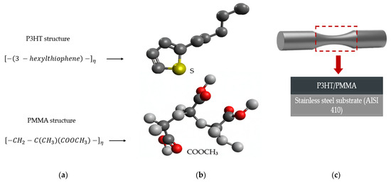
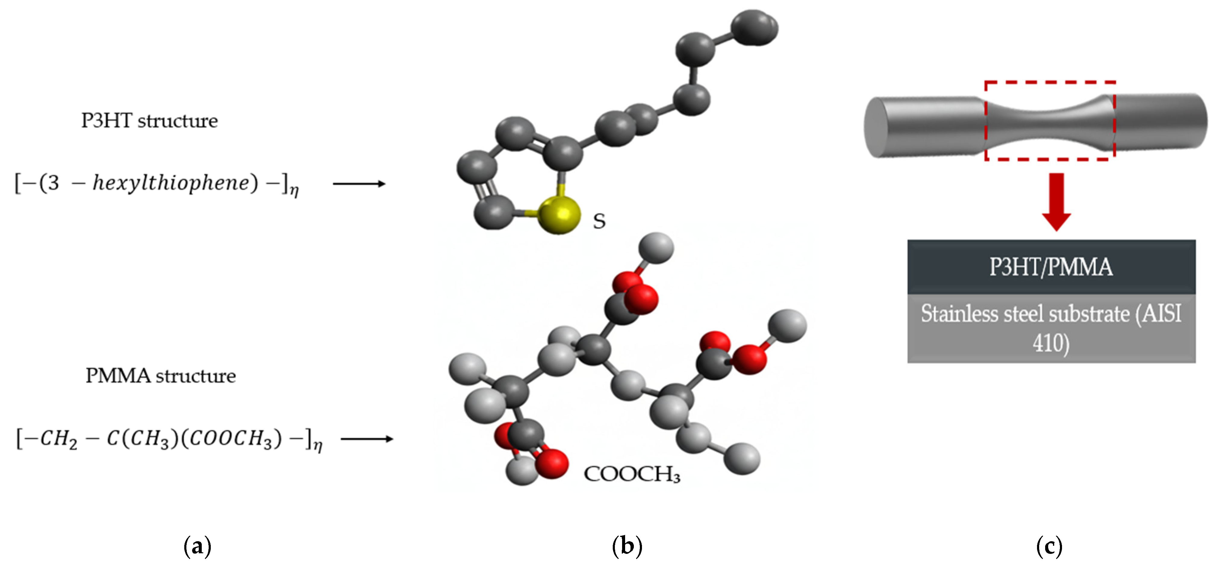
The adhesion of the coating to the steel is considered to involve both mechanical and physicochemical contributions. Mechanical anchoring is promoted by surface microroughness and substrate wettability, whereas physicochemical interactions may occur between polar functional groups in the coating, particularly the PMMA carbonyl , and the native oxide and hydroxide surface layer on steel through dipole interactions and hydrogen bonding. After coating application and conditioning, coating adhesion was evaluated according to ASTM D3359 (cross-hatch tape test), and coating thickness was measured to assess the initial condition and consistency of the coated specimens before exposure [17]. Based on post-tape inspection, the detached area was estimated to represent approximately 5%–15% of the evaluated region, indicating adequate adhesion with limited and localized delamination. The average dry film thickness of the P3HT/PMMA coating was approximately 100 μm. Figure 1 shows the chemical structure of P3HT and PMMA, together with a three-dimensional representation of short polymer chains (oligomers) used as a conceptual model of the coating, and a schematic of the coated sample illustrating the deposition of the P3HT/PMMA on the stainless steel substrate. In addition, Figure 2 presents representative images of the ASTM D3359 cross-hatch adhesion test (before cutting, after cross-hatching, and after tape removal).
Figure 1.
(a) Chemical structure of poly (3-hexylthiophene) (P3HT) and poly (methyl methacrylate) (PMMA); (b) three-dimensional representation of short polymer chains (oligomers) used to illustrate the polymeric structure; (c) schematic representation of the coated specimen, where the P3HT/PMMA coating is applied on the stainless steel substrate (AISI 410).
Figure 2.
Adhesion evaluation of the P3HT/PMMA coating using the cross-hatch tape test according to ASTM D3359: (a) initial condition of the coated surface prior to testing, showing a homogeneous and continuous coating layer; (b) orthogonal cross-hatch pattern introduced into the coating to assess interfacial adhesion between the coating and the metallic substrate; (c) surface after application and removal of the ASTM D3359 adhesive tape, showing partial coating detachment mainly at the grid intersections.
2.3. Corrosion and Electrochemical Measurement
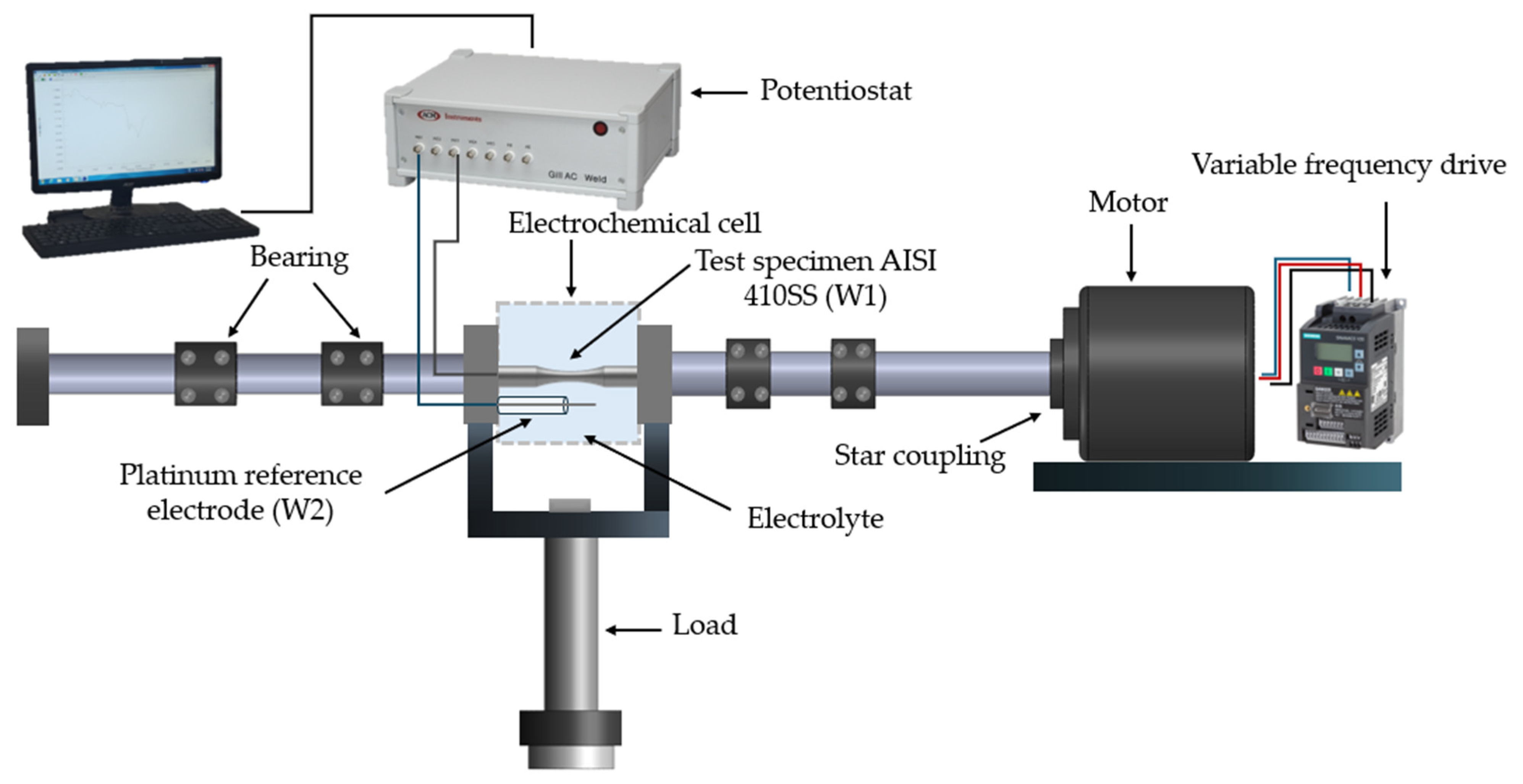
Corrosion fatigue tests were conducted in a 3 wt.% NaCl solution prepared with distilled water at room temperature. In order to reproduce the conditions of an electrochemical environment, a two-electrode electrochemical cell was set up: a working electrode (W1) made of AISI 410 stainless steel (specimen) and a platinum wire (0.5 mm in diameter and 50 mm in length) used as a quasi-reference electrode (W2). Electrochemical activity during corrosion fatigue testing was measured using a two-electrode electrochemical cell connected to an ACM instruments potentiostat model GILL AC (UK) and integrated with the rotating bending fatigue machine, enabling continuous exposure of the gauge section to the electrolyte. For both coated and uncoated specimens, the cell contained 40 mL of NaCl solution that covered only the gauge section; the grip areas were kept out of the electrolyte to avoid unintended electrochemical effects. The data obtained were analyzed to evaluate the electrochemical noise response associated with corrosion in the samples.
2.4. Corrosion Fatigue Test
Rotary bending corrosion fatigue tests were conducted using a Moore-type rotating bending machine, in which a midspan bending load is applied to generate the bending moment in the gauge section. The specimens were divided into two groups of four: the first consisting of uncoated specimens and the second of specimens coated with P3HT/PMMA. All tests were conducted at a frequency of 20 Hz, 1200 RPM, and four stress levels: 667, 583, 500, and 417 MPa. The specimens were subjected to cyclic loading , generating maximum stress on the external surfaces of the specimens. The applied stress (σ) for each test was determined using the following equation:
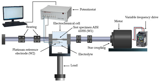
where is the moment, is the distance from the center to a point of interest on the specimen, and is the moment of inertia. During the tests, the coated section of the specimen remained in direct contact with the NaCl solution described in Section 2.3, allowing for the simultaneous action of mechanical loads and the corrosive medium. Subsequently, the recorded number of cycles was used to construct the σ vs. N curves. Figure 3 shows the experimental setup used for corrosion fatigue testing. In addition, the electrochemical noise technique was applied to analyze corrosion activity in the aqueous medium, providing relevant information on crack initiation and propagation.
Figure 3.
Experimental setup for corrosion fatigue testing.
2.5. Crack Propagation Rate Evaluation
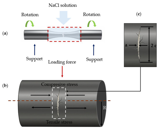
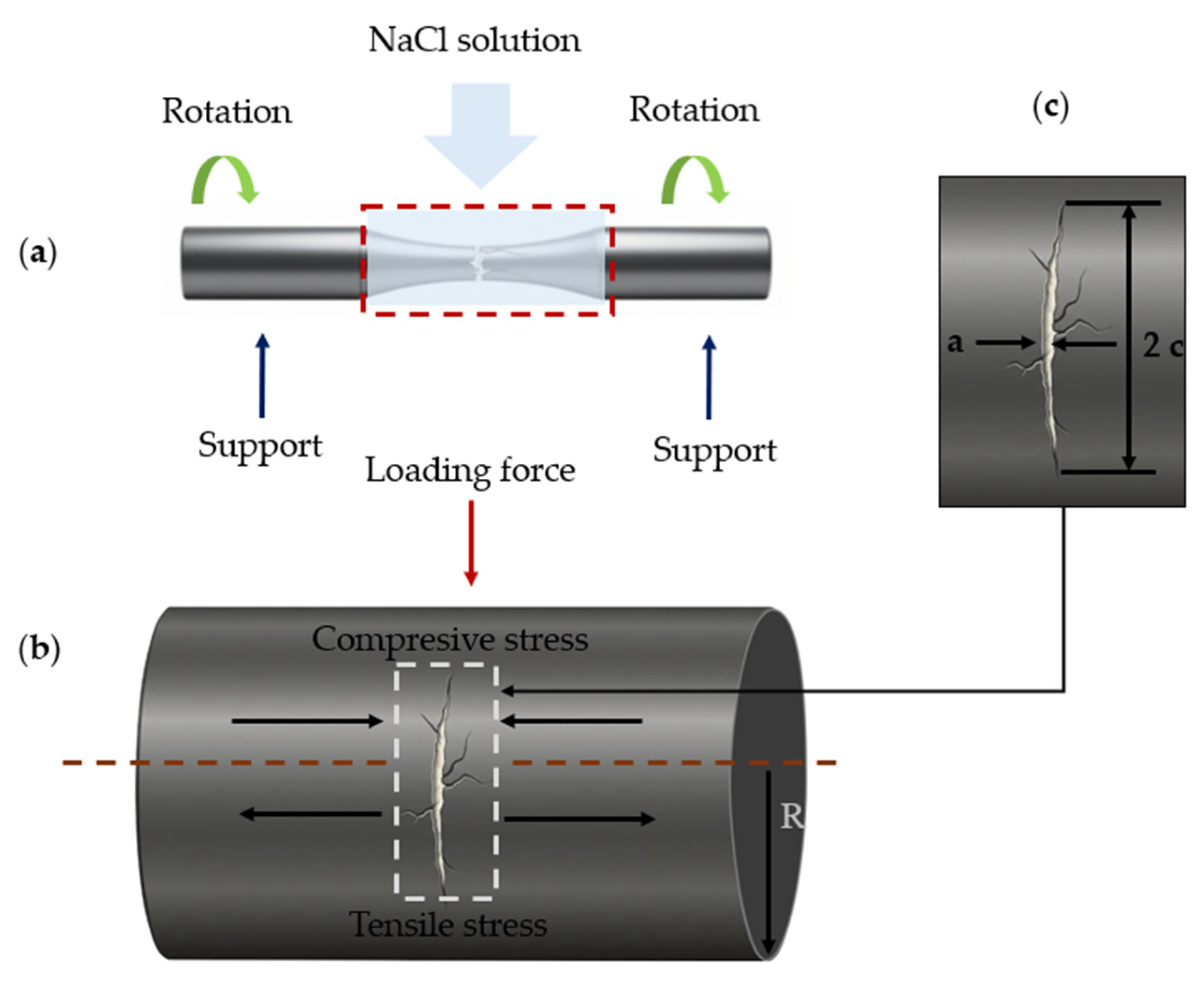
In the rotary bending and corrosion fatigue tests, the specimens were subjected to periodic tensile and compressive stresses in a corrosive environment. To evaluate crack propagation, the surface crack length along the circumference of the circular cross-section and the crack width were measured using SEM for both coated and uncoated specimens. Measurements of the cracks on the sample surface allowed the crack to be modeled as a semielliptical shape. Based on this geometry, crack growth was analyzed using linear elastic fracture mechanics based on the stress intensity factor . Figure 4 shows the geometric diagram of the crack.
Figure 4.
Test Corrosion Fatigue (a) Corrosion fatigue under rotational bending; (b) the specimen is subjected to periodic loading forces in a corrosive environment; (c) semielliptical surface of a crack.
The crack growth rate was determined using the Paris law, which relates the crack growth rate to the stress intensity factor range , as given by the following equation:
where and are dimensionless constants for AISI 410 steel, namely and , respectively [18]. Meanwhile, is determined to quantify the local stress at the crack tip, according to the following equation:
where is the nominal stress range applied to the specimen, is the crack size, and is a geometric factor that accounts for the crack conditions. In this case, values of were used for uncoated specimens and for coated specimens, a value used for surface cracks in cylindrical components valid for ratios, according to the following equation [18,19,20]:
3. Results
This section presents and analyzes the results of the corrosion fatigue in AISI 410 stainless steel with and without a P3HT/PMMA polymer coating exposed to 3 wt.% NaCl solution at room temperature. The analyses are structured as follows: (1) measurements of electrochemical noise in power to identify degradation processes at the interface between the metal, the polymer coating, and the NaCl solution; (2) interfacial degradation of the coated samples via SEM; (3) crack nucleation; (4) crack propagation rate ; (5) fatigue life; and (6) interaction mechanisms in fatigue corrosion controlled by cathodic delamination, with the aim of proposing a model explaining the synergistic behavior between cyclic tensile and compressive loads and the corrosive action in AISI 410 SS.
3.1. Electrochemical Noise Analysis During Corrosion Fatigue
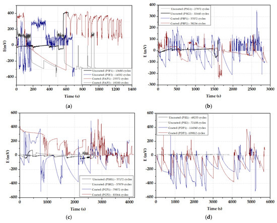
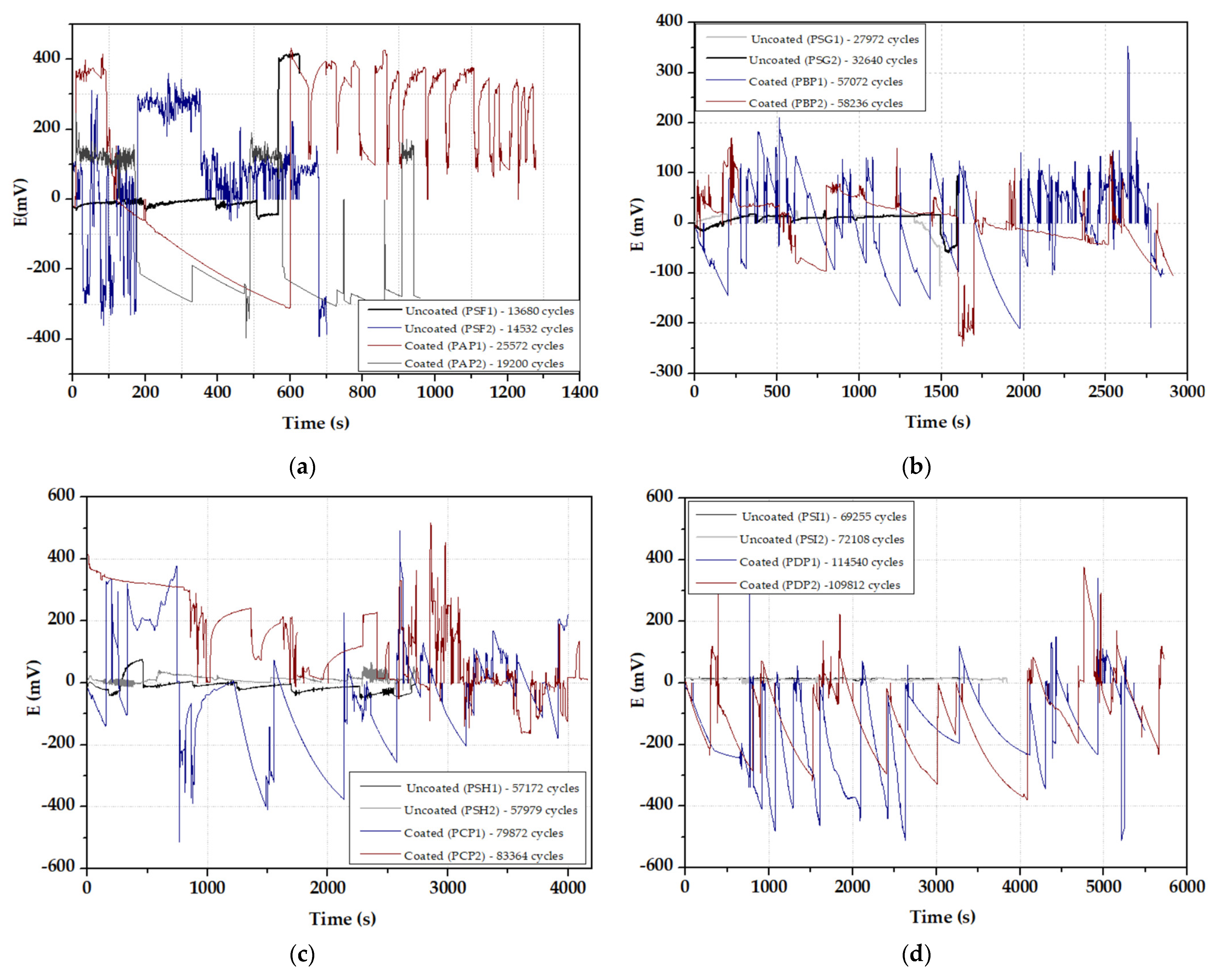
Electrochemical behavior during corrosion fatigue testing was evaluated by recording electrochemical noise patterns (ENP) under open-circuit conditions during cyclic loading, as shown in Figure 5. The ENP signals were obtained under mechanical fatigue conditions and following exposure to a 3 wt.% NaCl solution. Initially, the behavior of uncoated AISI 410 SS was analyzed to establish a reference for the corrosive process in direct contact with the aqueous solution. Subsequently, the steel with a P3HT/PMMA polymer coating was evaluated under the same cyclic loading conditions. The comparison between the two conditions allowed for the identification of the type of ENP, suggesting periodic behavior of positive and negative transients in both cases, indicating localized corrosion and passive recovery. On the other hand, the EPN time series for coated samples exhibits recurrent large-amplitude transients (abrupt potential excursions followed by gradual recovery) and saw tooth-like fluctuations, which are consistent with localized under-film electrochemical events and intermittent activation at the coating/substrate interface, because these features are observed from the early portion of the recordings, before clear evidence of advanced fatigue damage. The EPN response suggests that interfacial degradation begins during cyclic loading and precedes the later stages of corrosion fatigue damage evolution.
Figure 5.
Electrochemical potential noise (EPN) time series recorded under open circuit conditions during corrosion fatigue testing of AISI 410 SS in 3 wt.% NaCl solution, for uncoated samples and samples coated with P3HT/PMMA under maximum stresses of: (a) 667 MPa (80% ); (b) 583 MPa (70% ); (c) 500 MPa (60% ), and (d) 417 MPa (50% ), with a loading frequency and .
To evaluate electrochemical behavior under mechanical loading, the samples were tested under an alternating stress of 667 MPa (80% ). Under these conditions, differences were observed between uncoated and coated steel. The uncoated material exhibited white noise behavior with positive and negative transients associated with surface activation processes, leading to localized attack that caused pitting corrosion [21]. Potential shifts toward more negative values were recorded, followed by progressive recoveries, indicating the rupture of the passive layer during the cyclic opening of cracks and its subsequent repassivation. This behavior is consistent with the propagation of corrosion fatigue cracks controlled by repeated cycles of activation and reconstruction of the passive layer when the microcrack zones are exposed. Figure 4a shows this behavior in cycles 13,680 and 14,532, respectively.
In addition, the coated samples exhibited EPN different from those observed in the exposed steel. Abrupt shifts in potential were recorded in the range of +400 mV to −310 mV (25,572 cycles) and +200 mV to −380 mV (19,200 cycles), followed by gradual recoveries. This pattern is characteristic of localized activation at the interface between the coating and the steel surface (substrate), consistent with under-film corrosion processes. The transients are associated with the formation of anodic regions at coating defects, while the adjacent zones act as cathodic areas where oxygen reduction occurs, promoting progressive degradation of the coating adhesion (Figure 5a) [22,23,24].
The experimental potential time series RE obtained under a load of 583 MPa (70% ) for the uncoated samples at 32,640 and 27,972 cycles showed the same general trend observed previously. The electrochemical noise pattern remained uniform, with positive and negative transients of lesser magnitude than those obtained from the coated samples, associated with localized corrosion and repassivation. However, in the coated samples, an oscillation in the potential magnitude was observed in the range of approximately +370 mV to −250 mV. These fluctuations in the EPNs not only indicate localized electrochemical activity at the steel/coating interface at 57,072 and 58,236 cycles but also demonstrate the interaction between cyclic loading and interfacial degradation. When the coated samples are subjected to cyclic loading, plastic deformations occur repeatedly on the steel surface, generating shear stress at the interface between the coating and the substrate. This allows NaCl to penetrate, and in some areas, occluded cells from under the coating, where anodic dissolution leads to the nucleation of microcracks (Figure 5b).
The time series of potential under a 500 MPa loading cycle (60% ) exhibited a saw tooth pattern associated with localized corrosion processes in the uncoated samples at 57,172 and 57,959 cycles. The magnitude of the potential shifts toward more negative values, suggesting mechanisms of corrosion fatigue and passive layer rupture, leading to anodic dissolution processes that influence the nucleation of pitting and surface microcracks. For the coated samples, the saw tooth pattern at 79,872 and 83,364 cycles observed at the start of the recording is consistent with localized corrosion under the polymer coating due to cyclic deformation and NaCl penetration through the coating. However, around 1500 s and 2000 s, the pattern changes and the potential values oscillate in a range of +500 mV to −500 mV, suggesting a change associated with mechanical degradation of the coating and nucleation of microcracks where bare material is exposed to the electrolyte, followed by localized corrosion and passivation on the exposed material (Figure 5c).
Finally, the electrochemical behavior under a mechanical load of 417 MPa (50% ) was evaluated; the uncoated samples exhibited positive and negative potentials of less magnitude, in the range of approximately +20 mV to −4 mV, in cycles 69,255 and 72,108, respectively. This behavior suggests a more stable electrochemical response under electrolyte exposure, consisting of activation and repassivation processes. In contrast, the coated samples at 109,812 and 114,540 cycles exhibited transients in the form of high-amplitude peaks with fluctuations in the range of approximately +450 mV to −450 mV. These patterns indicate localized and metastable electrochemical events at the interface between the coating and the steel, consistent with the activation of microcells under the polymer. At this level of cyclic loading, the coating integrity is maintained over most of the sample surface, so the NaCl solution penetrates through isolated defects, generating transient responses of greater magnitude (Figure 5d).
Consequently, the electrochemical noise patterns showed significant differences between coated and uncoated steel. The samples with the P3HT/PMMA polymer exhibited transients of a higher amplitude than the uncoated samples , suggesting increased localized electrochemical instability under the polymer film. This behavior is due to confined cell conditions under the coating and local separation of anodic and cathodic regions at the coating/substrate interface, in contrast to the surface exposed to the electrolyte. As a result, these electrochemical patterns point to an interfacial degradation process that is analyzed in the following section through morphological evidence.
3.2. Interfacial Degradation
The surface morphology of AISI 410 stainless steel samples coated with P3HT/PMMA polymer was examined in terms of degradation resulting from the electrochemical interaction between the coated steel system and the corrosive environment, as well as from cyclic loading. The polymer coating suffers progressive damage resulting from the synergistic combination of electrochemical and mechanical effects. Initially, the polymer coating acts as a diffusion barrier to control and slow down the transport of chloride ions toward the stainless steel substrate. However, fatigue induced by cyclic tensile and compressive stress leads to the formation of microcracks and plastic deformation in the polymer matrix. These microcracks allow the diffusion of aggressive species toward the metal substrate, leading to a partial loss of adhesion between the coating and the stainless steel.
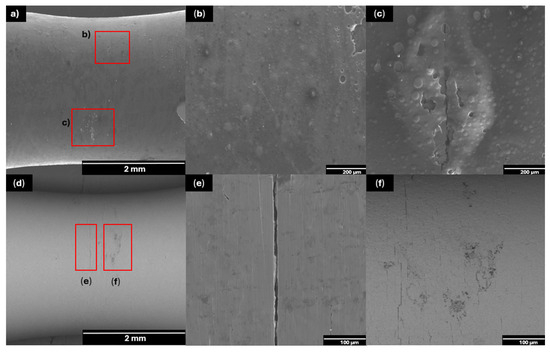
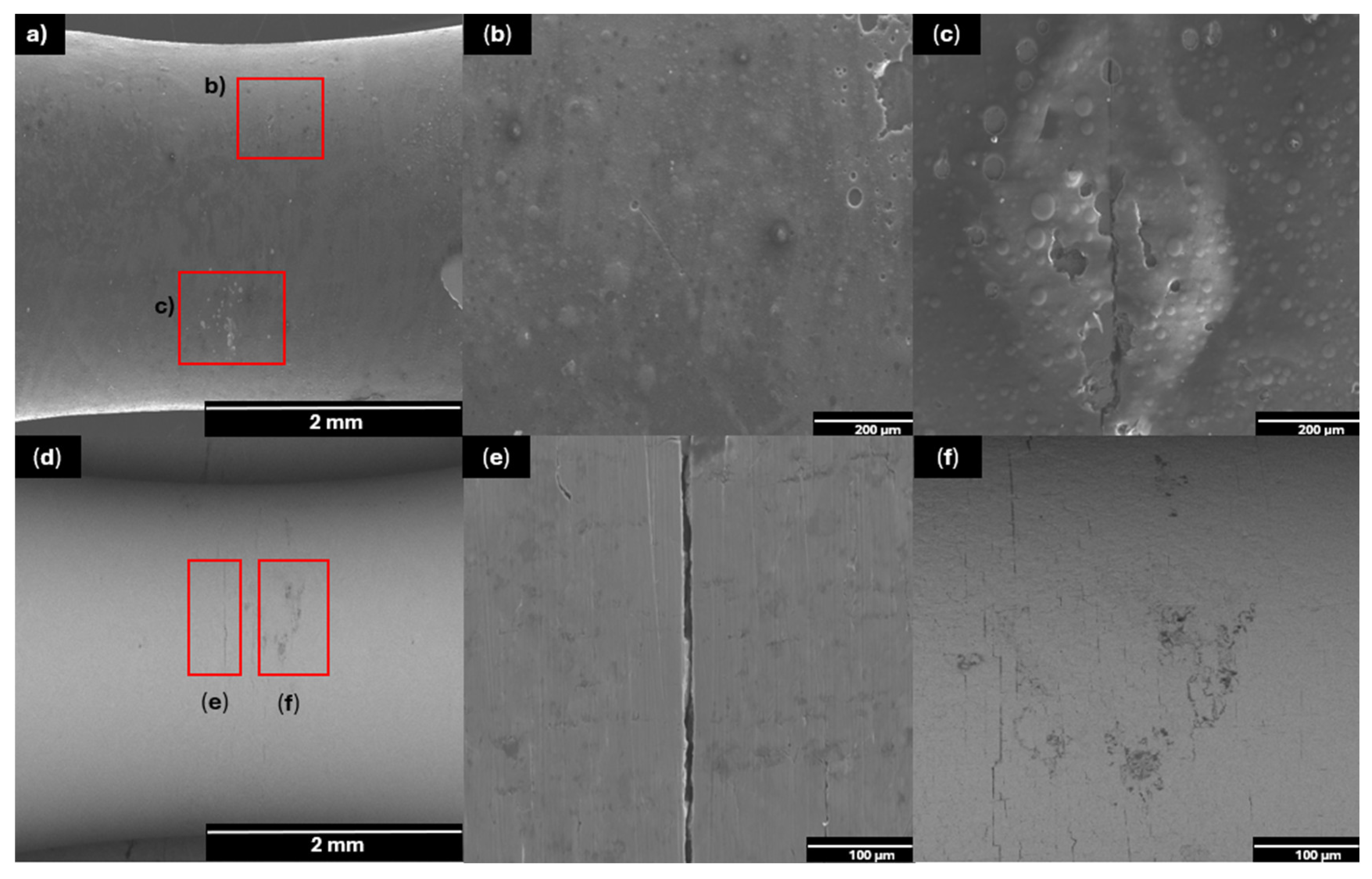
During this process, sodium chloride ions penetrate through cracks in the polymer coating, triggering a corrosion process characterized by localized anodic dissolution, passivation, and repassivation of the stainless steel. This process alters the microstructure of both the polymer and the substrate, leading to pitting corrosion, microcracks in the polymer, and the nucleation of microcracks that act as stress concentrators and accelerate the propagation of cracks in corrosion fatigue. Figure 6, Figure 7, Figure 8 and Figure 9 show the most relevant images, obtained via scanning electron microscopy (SEM), of the sequential evolution of the surface morphology and the degradation mechanism of the coated steel, following its exposure to corrosion fatigue conditions in a 3 wt.% NaCl solution at different load cycle numbers: 667 MPa, 583 MPa, 500 MPa, and 417 MPa.
Figure 6.
Corrosion fatigue evaluation of P3HT/PMMA-coated AISI 410 SS exposed to NaCl at 667 MPa. SEM micrographs show representative regions of the specimen after corrosion fatigue: (a) Surface crack in the polymer coating; (b) localized coating delamination with loss of interfacial adhesion; (c) crack initiation and microcracks in the polymer film; (d) substrate surface after coating removal; (e) crack on the sample surface; (f) cracks on the sample surface and pitting corrosion.
Figure 7.
Corrosion fatigue evaluation of P3HT/PMMA-coated AISI 410 SS exposed to NaCl at 583 MPa. SEM micrographs show representations of the same specimen after corrosion fatigue: (a) delamination of the polymer at the neck of the specimen; (b) blister formation on the polymer coating; (c) microcracks on the substrate; (d) substrate surface after coating removal; (e) cracks on the specimen surfaces; (f) pitting corrosion.
Figure 8.
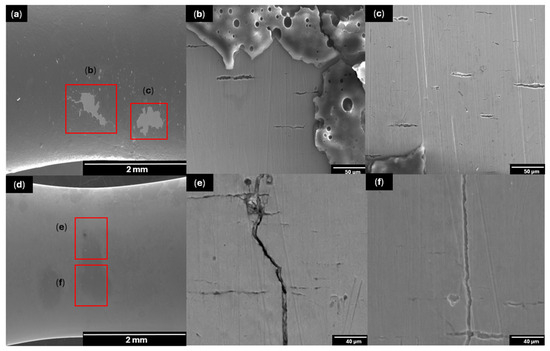
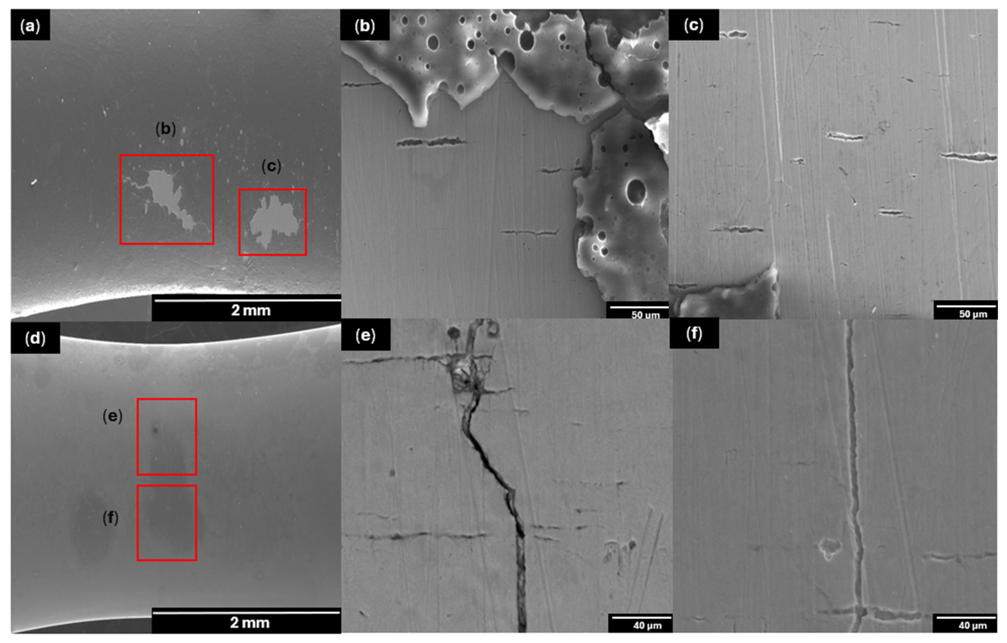
Corrosion fatigue evaluation of P3HT/PMMA-coated AISI 410 SS exposed to NaCl at 500 MPa. SEM micrographs show representations of the same specimen after corrosion fatigue: (a) coating delamination at the specimen neck; (b) localized delamination accompanied by microcrack formation in the polymer film; (c) microcracks in the coating; (d) substrate surface after coating removal; (e) pitting features and cracks on the exposed substrate; (f) cracks on the specimen surface and pitting corrosion.
Figure 9.
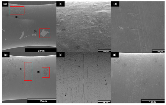
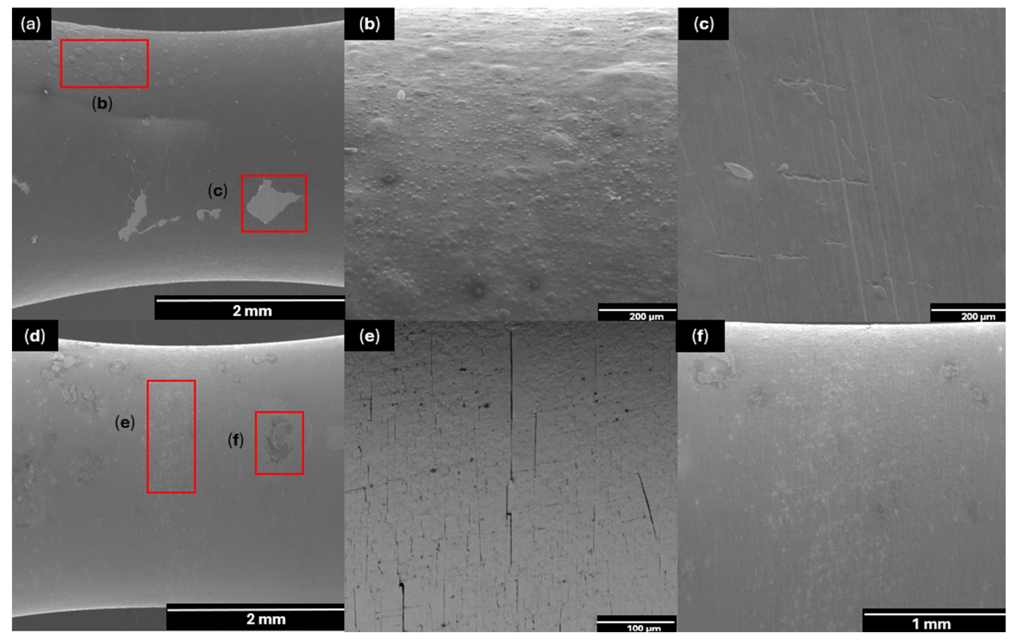
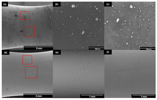
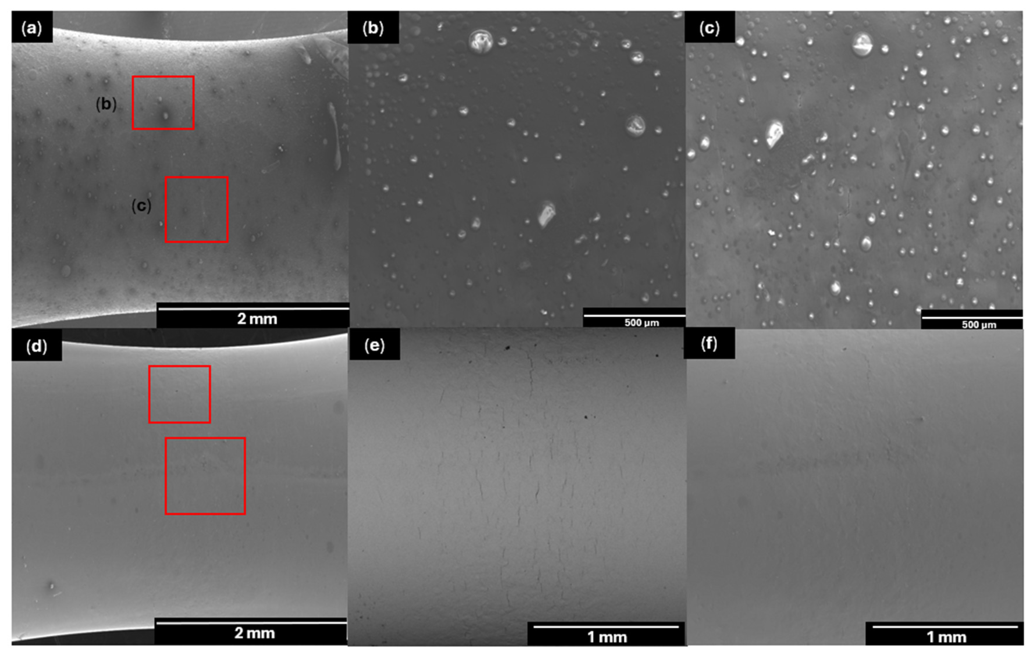
Corrosion fatigue evaluation of P3HT/PMMA-coated AISI 410 SS exposed to NaCl at 417 MPa. SEM micrographs show representations of the same specimen after corrosion fatigue: (a) Surface crack in the polymer coating; (b) salt deposits on the coating surface; (c) salt deposits and microcracks in the polymer coating; (d) substrate surface after coating removal; (e) localized pitting features on the exposed substrate; (f) cracks on the sample surface and pitting corrosion.
Initially, microcracks were identified in the polymer coating, which are consistent with the combined action of the corrosive environment and cyclic loading, where localized stress concentrations promote coating damage (Figure 6a and Figure 7b). These microcracks can be promoted by cyclic deformation of the coating and by changes in the polymer’s mechanical response during exposure to the NaCl solution. The presence of microcracks provides a preferential pathway for electrolyte ingress and promotes interfacial degradation at the coating/substrate interface, facilitating localized ion transport toward the steel surface. However, rather than implying a time-resolved progression, the observation reported here reflects a comparative trend across stress levels and representative regions of the same samples (before and after coating removal). However, although the coating functions as a protective barrier, its impermeability is now incomplete [25,26].
On the other hand, blistering was observed in microzones of the polymer coating, suggesting the accumulation of species under the film and degradation of the coating/substrate interface (Figure 6b and Figure 7a,b). These blisters can be attributed to the absorption of the sodium chloride solution, which generates hygroscopic stresses in the coating plane and surface instability, resulting in a loss of adhesion. As the samples are subjected to fatigue and the simultaneous action of the corrosive medium, the loss of adhesion effect also intensifies due to the diffusion of sodium chloride ions through the weakened microzones of the P3HT/PMMA, allowing the formation of corrosion products at the steel/coating interface. The formation of corrosion products increases the internal pressure of the blister and promotes its growth; as a result, the polymer retains its surface continuity in the form of local swelling, but its function as a protective barrier begins to lose adhesion and eventually leads to the formation of an anodic environment within the blister, which may anticipate subsequent stages of damage [27,28,29].
Similarly, in the samples subjected to higher stress levels, more severe degradation of the P3HT/PMMA coating was observed. The polymer film exhibited localized cracking, which exposed the substrate (Figure 6c, Figure 7c and Figure 8a–c). In these areas, microcracks were identified on the steel surface that originated under the cracked coating. Smooth and rough areas were also observed on the coating surfaces, indicative of brittle fracture as a viscoelastic response dependent on time and the cyclic loading to which the sample was exposed [30]. The presence of rough areas or branched microcracks in the polymer coating also indicates that the corrosive environment leads to local degradation of the polymer, reducing its molecular cohesion. This mechanism is consistent with crack growth in polymeric and viscoelastic materials, where microcrack propagation occurs progressively until critical conditions are reached [25,31,32,33,34]. In addition, hemispherical structures distributed across the polymer surface were observed on the samples coated at lower loading levels (Figure 9a–c). These formations, described as micro-blistering, are associated with a localized hygroscopic effect that represents an early stage of damage preceding macroscopic blistering. This type of surface degradation is consistent with localized electrochemical events under the polymer film, even though the coating retains its uniformity.
Finally, after removing the P3HT/PMMA coating with solvents, the substrate surfaces were analyzed by SEM. This procedure revealed that the load level influences the type of damage that develops on the coating and substrate. At higher stress levels, greater damage to the coating was observed, characterized by film fracture and cracks predominantly on the steel (Figure 6e,f and Figure 7e,f). However, at lower load levels, the damage was less severe, with smaller microcracks and the presence of slip bands on the steel predominating, suggesting a localized plastic deformation process leading to early crack nucleation (Figure 8e,f and Figure 9e,f).
3.3. Crack Propagation Rate
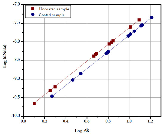
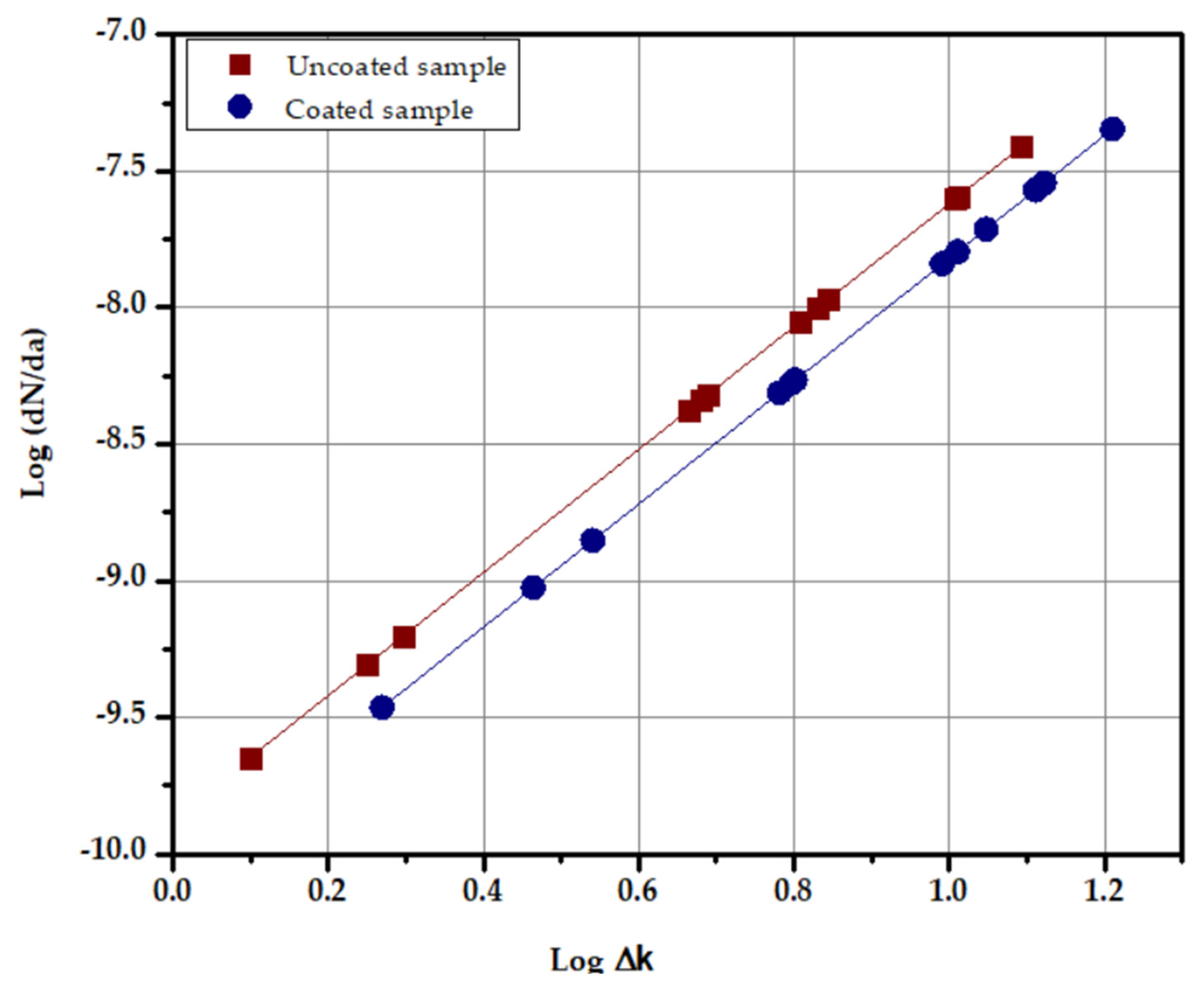
The data for evaluating the crack propagation rate was obtained under experimental conditions of and . Figure 10 shows the relationship between the fatigue crack propagation rate in a 3 wt.% NaCl solution corrosive environment and the stress intensity range for uncoated steel specimens and those with a polymer coating. In the uncoated samples, it is observed that the curve tends toward a greater increase in crack propagation rate. This behavior is due to the synergistic effect between corrosion and fatigue loading, as the exposure of steel to NaCl promotes anodic dissolution on its surface, giving rise to pitting corrosion that acts as a stress concentrator. These pits promote the nucleation of microcracks under the action of loading cycles. As the steel is exposed to the corrosive environment, it undergoes passivation and repassivation processes. Under these conditions, the synergy between loading cycles, anodic dissolution, and repassivation accelerates crack propagation [35,36].
Figure 10.
Crack growth rate (da/dN) as a function of the stress intensity factor range (ΔK) for AISI 410 stainless steel uncoated and P3HT/PMMA-coated samples tested in 3 wt.% NaCl solution at room temperature under cyclic loads of ∆σ = 667 MPa, 583 MPa, 500 MPa, and 417 MPa. Load frequency f = 20 Hz.
On the other hand, samples coated with P3HT/PMMA polymer exhibit a lower crack propagation rate, as the polymer acts as a protective barrier against chloride ions and moisture. Initially, the polymer coating adheres strongly to the steel surface, preventing the formation of pitting corrosion. However, as the process progresses, the appearance of microcracks and the local loss of coating adhesion are affected by the loading cycles. Under these conditions, delamination of the polymer from the steel surface occurs, and the penetration of the corrosive solution reactivates the electrochemical process between the steel and the polymer. This process results in an increase in the crack propagation rate and a progressive convergence toward the curve of uncoated steel.
3.4. Fatigue Life (S-N)
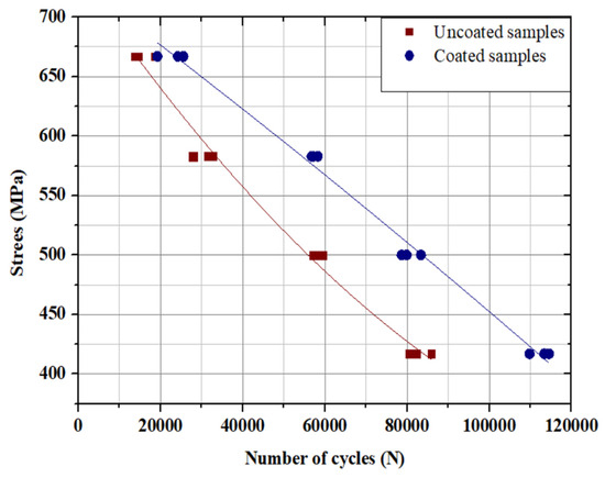
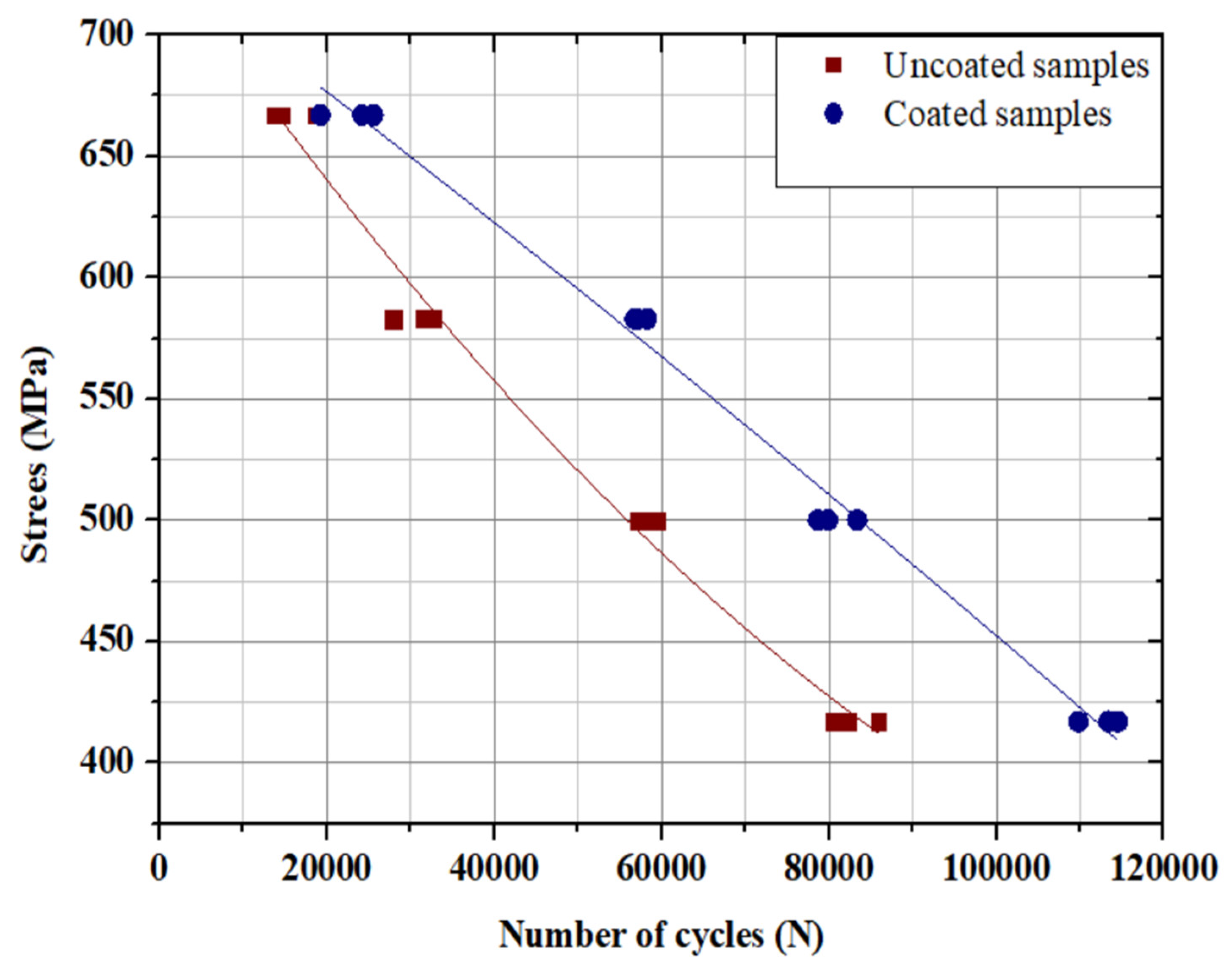
The stress versus cycle number curves were obtained from samples exposed to 3 wt.% NaCl solution, comparing uncoated samples with those coated with P3HT/PMMA. Figure 11 shows the S-N curve from corrosion fatigue tests, indicating that the number of cycles decreases as the applied stress increases. However, the corrosive environment significantly affected the uncoated stainless steel samples, which had shorter fatigue life. Nevertheless, at the same stress level, the polymer/coated stainless steel exhibited greater fatigue resistance. For example, at 500 MPa, the specimens coated with P3HT/PMMA withstood an average of 9.3 × 10⁴ cycles compared to 5.7 × 10⁴ for the samples directly exposed to the corrosive medium, due to pitting formation on the steel surface, which is promoted by exposure to NaCl and anodic zones that act as stress concentrators, favoring the initiation of microcracks and their propagation through anodic dissolution. On the contrary, the polymer coating acted as an electrochemical and physical barrier that limited the penetration of NaCl ions into the steel surface, thereby delaying microcrack nucleation and reducing the crack propagation rate, demonstrating the ability of the polymer coating to reduce the effects of corrosion during fatigue loading by 50%, thus increasing the service life of stainless steel.
Figure 11.
S-N curve for AISI 410 SS with a P3HT/PMMA coating and without a polymer coating, exposed to 3 wt.% NaCl solution at room temperature under a maximum cyclic stress of ∆σ = 667 MPa, 583 MPa, 500 MPa, and 417 MPa. Loading frequency f = 20 Hz.
3.5. Proposed Corrosion Fatigue Interaction Mechanism
Cathodic delamination is a degradation mechanism in a coated metal exposed to corrosive environments, caused by the loss of adhesion of the polymeric coating, which compromises its performance and accelerates damage to the substrate. This mechanism occurs in coatings that detach from local defects where the corrosive solution reaches the interface. The presence and mobility of cations, as well as the increase in interfacial pH, are related to oxygen reduction, which leads to loss of adhesion, indicating that ionic transport through the film thickness is the mechanism controlling the detachment kinetics, as evidenced by the correlation between the rate of debonding and the diffusivity of cations in the coating under cathodic conditions [12].
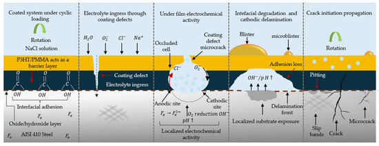
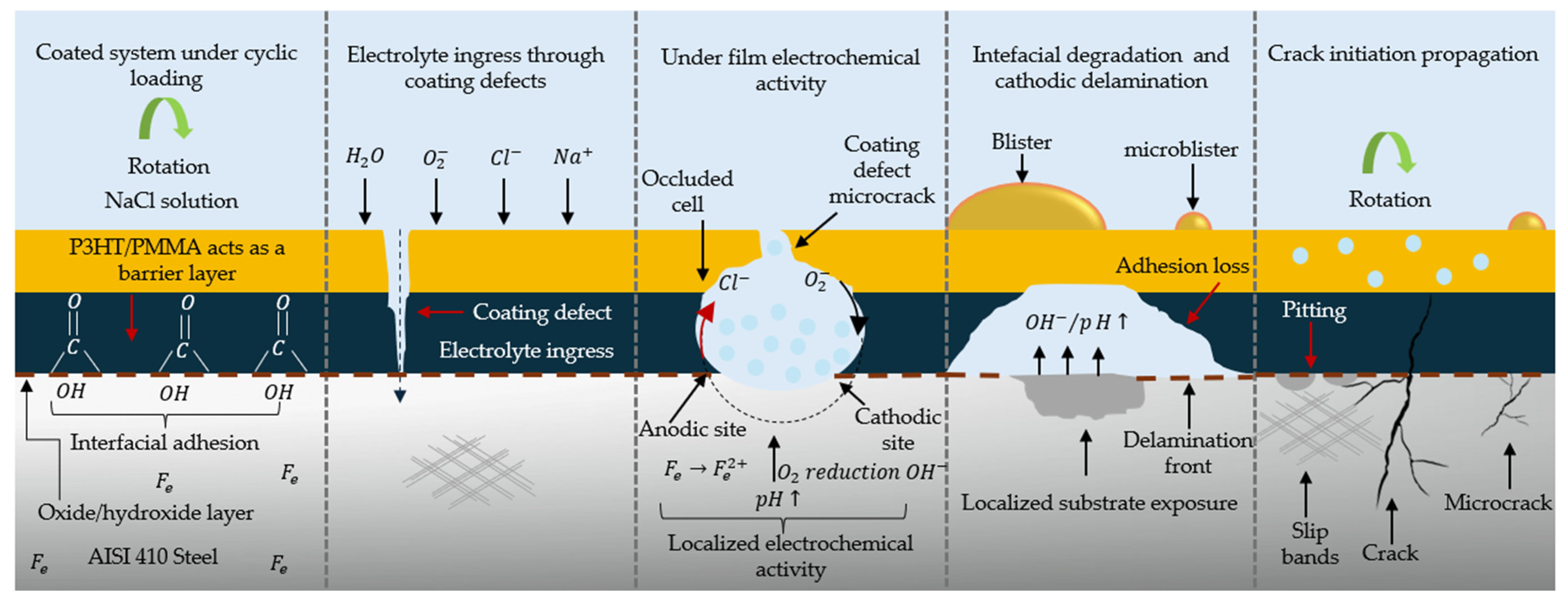
Consequently, based on the electrochemical noise results, SEM observations, and the crack nucleation and propagation behavior, a mechanism for corrosion fatigue interaction is proposed for P3HT/PMMA-coated AISI 410 steel exposed to 3 wt.% NaCl solution (Figure 12). Initially, the electrolyte (H2O, O2, and Cl−) penetrates the coating through defects or microcracks induced by cyclic loading, promoting localized swelling of the polymer and the formation of microblisters and blisters. This early degradation leads to confined conditions beneath the film and localized electrochemical activation at the coating/substrate interface.
Figure 12.
Schematic diagram of the proposed mechanism of corrosion fatigue interaction in AISI 410 stainless steel coated with P3HT/PMMA and exposed to a 3 wt.%NaCl solution. Note: Arrows indicate species ingress (black), cyclic rotation (green), and localized attack/transport paths (red). The brown dashed line denotes the coating–substrate interface; vertical dashed lines separate stages; the dotted circle indicates an occluded electrochemical cell beneath the coating.
Once the electrolyte reaches the interface, an occluded cell is formed beneath the polymer film, with localized anodic and cathodic regions. In the anodic region, iron dissolution occurs according to the following equation:
While in the cathodic region, oxygen is reduced, with the generation of hydroxyl ions according to the following equation:
The production of (OH−) increases the interfacial pH, weakening the coating adhesion and leading to cathodic delamination, which progressively and locally exposes the substrate, in this case, stainless steel, to the corrosive environment. In these exposed areas, cyclic loading promotes localized plastic deformation (slip bands) and crack nucleation from corrosion pitting. Ultimately, these microcracks propagate due to the combined effect of cyclic stresses and localized dissolution, resulting in the crack propagation characteristic of corrosion fatigue.
4. Conclusions
The present study demonstrated that the corrosion fatigue behavior of P3HT/PMMA-coated AISI 410 stainless steel is controlled by interfacial degradation mechanisms associated with cathodic delamination. The combined electrochemical, microstructural, and mechanical analyses confirmed that localized loss of adhesion progressively exposes the substrate to the corrosive environment, promoting crack nucleation and accelerating crack propagation under cyclic loading conditions. Nevertheless, despite the occurrence of interfacial degradation, the polymeric coating provided a significant improvement in corrosion fatigue resistance compared with uncoated steel:
- (1)
- The electrochemical noise in the potential during corrosion fatigue showed significantly higher amplitudes for AISI 410 steel coated with P3HT/PMMA (≈±400 mV) than for uncoated steels (≈±200 mV), indicating greater localized electrochemical instability under the film.
- (2)
- SEM analysis revealed progressive deterioration of the coating and interface, characterized by the formation of microblisters and blisters under low stress, and cracking/delamination under high stress, which compromised the coating adhesion and led to substrate exposure.
- (3)
- Electrochemical noise and SEM evidence indicate localized interfacial degradation consistent with cathodic delamination, while the P3HT/PMMA coating still provided improved overall corrosion fatigue resistance compared with uncoated steel.
- (4)
- Early cracking occurred in locally exposed areas of the substrate, associated with previous damage to the coating or the interface, and was related to localized plastic deformation induced by slip bands under corrosion fatigue conditions.
- (5)
- The results showed lower crack growth rates for P3HT/PMMA-coated AISI 410 than for uncoated steel at the same ; for example, at MPa , the coated condition exhibited log compared with for uncoated steel, corresponding to an reduction, indicating that coating delays corrosion fatigue crack propagation.
- (6)
- The S-N result confirmed the expected inverse relationship between applied stress and fatigue life. At 667 MPa (80% ), the P3HT/PMMA-coated samples sustained 25,572 cycles compared with 18,576 cycles for uncoated steel, corresponding to an % increase in fatigue life in 3 wt.% NaCl solution.
Author Contributions
C.M.C.M.: Conceptualization, methodology, investigation, formal analysis, data curation, visualization, and writing—original draft, project administration. M.A.Z.G.: Conceptualization, methodology, validation, and project administration. J.C.G.C.: Methodology, supervision, and writing—review. J.O.D.R.: Conceptualization, writing—review. L.R.P.: Conceptualization, methodology, and validation. All authors have read and agreed to the published version of the manuscript.
Funding
This research received no external funding.
Institutional Review Board Statement
Not applicable.
Informed Consent Statement
Not applicable.
Data Availability Statement
The original contributions presented in this study are included in the article. Further inquiries can be directed to the corresponding author.
Conflicts of Interest
The authors declare no conflict of interest.
References
- Larrosa, N.O.; Akid, R.; Ainsworth, R.A. Corrosion-Fatigue: A Review of Damage Tolerance Models. Int. Mater. Rev. 2018, 63, 283–308. [Google Scholar] [CrossRef] [Scilit]
- Duquette, D.J. Corrosion Fatigue. In Corrosion Mechanisms; CRC Press: Filadelfia, PA, USA, 2020; pp. 367–395. [Google Scholar]
- Jie, Z.; Zhang, Z.; Susmel, L.; Zhang, L.; Lu, W. Corrosion Fatigue Mechanisms and Evaluation Methods of High-strength Steel Wires: A state-of-the-art review. Fatigue Fract. Eng. Mater. Struct. 2024, 47, 2287–2318. [Google Scholar] [CrossRef] [Scilit]
- Mansor, N.I.I.; Abdullah, S.; Ariffin, A.K.; Syarif, J. A Review of the Fatigue Failure Mechanism of Metallic Materials under a Corroded Environment. Eng. Fail. Anal. 2014, 42, 353–365. [Google Scholar] [CrossRef] [Scilit]
- Ma, X.; Yang, F.; Li, J.; Xue, Y.; Guan, Z. Fatigue Life Assessment Method of In-Service Mechanical Structure. Adv. Mech. Eng. 2021, 13, 168781402199652. [Google Scholar] [CrossRef] [Scilit]
- Shin, A.; Shon, M. Effects of Coating Thickness and Surface Treatment on the Corrosion Protection of Diglycidyl Ether Bisphenol-A Based Epoxy Coated Carbon Steel. J. Ind. Eng. Chem. 2010, 16, 884–890. [Google Scholar] [CrossRef] [Scilit]
- Ohtsuka, T. Corrosion Protection of Steels by Conducting Polymer Coating. Int. J. Corros. 2012, 2012, 915090. [Google Scholar] [CrossRef] [Scilit]
- Encinas-Sánchez, V.; Macías-García, A.; Díaz-Díez, M.A.; Brito, P.; Cardoso, D. Influence of the Quality and Uniformity of Ceramic Coatings on Corrosion Resistance. Ceram. Int. 2015, 41, 5138–5146. [Google Scholar] [CrossRef] [Scilit]
- Song, G.-L.; Feng, Z. Modification, degradation and evaluation of a few organic coatings for some marine applications. Corros. Mater. Degrad. 2020, 1, 408–442. [Google Scholar] [CrossRef] [Scilit]
- Critchlow, G.W.; Webb, P.W.; Tremlett, C.J.; Brown, K. Chemical Conversion Coatings for Structural Adhesive Bonding of Plain Carbon Steels. Int. J. Adhes. Adhes. 2000, 20, 113–122. [Google Scholar] [CrossRef] [Scilit]
- Lyon, S.B.; Bingham, R.; Mills, D.J. Advances in corrosion protection by organic coatings: What we know and what we would like to know. Prog. Org. Coat. 2017, 102, 2–7. [Google Scholar] [CrossRef] [Scilit]
- Leidheiser, H., Jr.; Wang, W.; Igetoft, L. The Mechanism for the Cathodic Delamination of Organic Coatings from a Metal Surface. Prog. Org. Coat. 1983, 11, 19–40. [Google Scholar] [CrossRef] [Scilit]
- Ramírez, J.A.R.; Mirafuentes, C.M.C.; Zalapa Garibay, M.A.; Castrejón, J.C.G.; Anaya, L.G.G. Corrosion Fatigue Analysis in Power Steam Turbine Blade. Metals 2023, 13, 544. [Google Scholar] [CrossRef] [Scilit]
- ASTM 466-15; Standard Practice for Conducting Force Controlled Constant Amplitude Axial Fatigue Tests of Metallic Materials. ASTM International: West Conshohocken, PA, USA, 2021. Available online: https://www.astm.org/e0466-15.html (accessed on 24 February 2026).
- ASTM G1-03; Standard Practice for Preparing, Cleaning, and Evaluating Corrosion Test Specimens. ASTM International: West Conshohocken, PA, USA, 2017. Available online: https://www.astm.org/g0001-03r17e01.html (accessed on 24 February 2026).
- ASTM G31; Standard Practice for Laboratory Immersion Corrosion Testing of Metal. ASTM International: West Conshohocken, PA, USA, 2012. Available online: https://www.astm.org/g0031-72r04.html (accessed on 25 February 2026).
- ASTM D3359-23; ASTM International. Standard Test Methods for Rating Adhesion by Tape Test. ASTM International: West Conshohocken, PA, USA. Available online: https://www.astm.org/d3359-23.html (accessed on 10 March 2026).
- Tada, H.; Paris, P.C.; Irwin, G.R. Stress Analysis of Cracks Handbook, 3rd ed.; American Society of Mechanical Engineers; ASME Press: Fairfield, CA, USA, 2000; ISBN 9780791801536. [Google Scholar]
- Arana, J.L.; González, J.J. Fracture Mechanics; Euskal Herriko Unibersitatea, Argitalpen Zerbitzua: Guipúzcoa, Spain, 2002; pp. 55–58. [Google Scholar]
- Anderson, T.L. Fracture Mechanics: Fundamentals and Applications, 3rd ed.; CRC Press: Boca Ratón, FL, USA, 2005; ISBN 9781420058215. [Google Scholar]
- Girija, S.; Mudali, U.K.; Raju, V.R.; Dayal, R.K.; Khatak, H.S.; Raj, B. Determination of Corrosion Types for AISI Type 304L Stainless Steel Using Electrochemical Noise Method. Mater. Sci. Eng. A Struct. Mater. 2005, 407, 188–195. [Google Scholar] [CrossRef] [Scilit]
- Jamali, S.S.; Mills, D.J. A Critical Review of Electrochemical Noise Measurement as a Tool for Evaluation of Organic Coatings. Prog. Org. Coat. 2016, 95, 26–37. [Google Scholar] [CrossRef] [Scilit]
- Trentin, A.; Pakseresht, A.; Duran, A.; Castro, Y.; Galusek, D. Electrochemical Characterization of Polymeric Coatings for Corrosion Protection: A Review of Advances and Perspectives. Polymers 2022, 14, 2306. [Google Scholar] [CrossRef] [Scilit]
- Frankel, G.S. Fundamentals of Corrosion Kinetics. In Active Protective Coatings; Springer Netherlands: Dordrecht, The Netherland, 2016; pp. 17–32. ISBN 9789401775380. [Google Scholar]
- Leterrier, Y.; Mottet, A.; Bouquet, N.; Gilliéron, D.; Dumont, P.; Pinyol, A.; Lalande, L.; Waller, J.H.; Månson, J.-A.E. Mechanical Integrity of Thin Inorganic Coatings on Polymer Substrates under Quasi-Static, Thermal and Fatigue Loadings. Thin Solid Films 2010, 519, 1729–1737. [Google Scholar] [CrossRef] [Scilit]
- Nabil Bassim, M.; Yannacopoulos, S.; Chaturvedi, M.C. A Study of the Role of Polymeric Coating in Preventing Corrosion Fatigue of Steels. Can. Metall. Q. 1988, 27, 79–83. [Google Scholar] [CrossRef]
- Effendy, S.; Zhou, T.; Eichman, H.; Petr, M.; Bazant, M.Z. Blistering Failure of Elastic Coatings with Applications to Corrosion Resistance. Soft Matter 2021, 17, 9480–9498. [Google Scholar] [CrossRef] [Scilit]
- Tu, Y.; Spelt, J.K. Blistering as a Form of Degradation in Adhesive Joints. J. Adhes. 2000, 72, 359–372. [Google Scholar] [CrossRef] [Scilit]
- Saarimaa, V.; Virtanen, M.; Laihinen, T.; Laurila, K.; Väisänen, P. Blistering of Color Coated Steel: Use of Broad Ion Beam Milling to Examine Degradation Phenomena and Coating Defects. Surf. Coat. Technol. 2022, 448, 128913. [Google Scholar] [CrossRef] [Scilit]
- Mars, W.; Fatemi, A. A Literature Survey on Fatigue Analysis Approaches for Rubber. Int. J. Fatigue 2002, 24, 949–961. [Google Scholar] [CrossRef] [Scilit]
- Hertzberg, R.W.; Nordberg, H.; Manson, J.A. Fatigue Crack Propagation in Polymeric Materials. J. Mater. Sci. 1970, 5, 521–526. [Google Scholar] [CrossRef] [Scilit]
- Chhipa, S.M.; Sharma, S.; Kumar Bagha, A. Recent Development in Polymer Coating to Prevent Corrosion in Metals: A Review. Mater. Today Proc. 2024, in press. [Google Scholar] [CrossRef] [Scilit]
- Bistac, S.; Vallat, M.F.; Schultz, J. Durability of Steel/Polymer Adhesion in an Aqueous Environment. Int. J. Adhes. Adhes. 1998, 18, 365–369. [Google Scholar] [CrossRef] [Scilit]
- Demiral, M. Strength in Adhesion: A Multi-Mechanics Review Covering Tensile, Shear, Fracture, Fatigue, Creep, and Impact Behavior of Polymer Bonding in Composites. Polymers 2025, 17, 2600. [Google Scholar] [CrossRef] [Scilit] [PubMed]
- Pedeferri, P. Corrosion Science and Engineering; Springer International Publishing: Cham, Switzerland, 2018; ISBN 9783319976242. [Google Scholar]
- Ge, H.; Le, J.-L.; Mantell, S.C. Numerical Modeling of Stress Corrosion Cracking of Polymers. Eng. Fract. Mech. 2016, 160, 199–212. [Google Scholar] [CrossRef] [Scilit]

Disclaimer/Publisher’s Note: The statements, opinions and data contained in all publications are solely those of the individual author(s) and contributor(s) and not of MDPI and/or the editor(s). MDPI and/or the editor(s) disclaim responsibility for any injury to people or property resulting from any ideas, methods, instructions or products referred to in the content. |
© 2026 by the authors. Licensee MDPI, Basel, Switzerland. This article is an open access article distributed under the terms and conditions of the Creative Commons Attribution (CC BY) license.