

Numerical Evaluation of Modified Mortar Coatings for Thermal Protection of Reinforced Concrete and Steel Structures Under Standardized Fire Exposure

Abstract
1. Introduction
2. Materials and Methods
2.1. Mortar Characteristics, Parameters and Nomenclatures
2.2. Beams Cross-Sectional Geometries
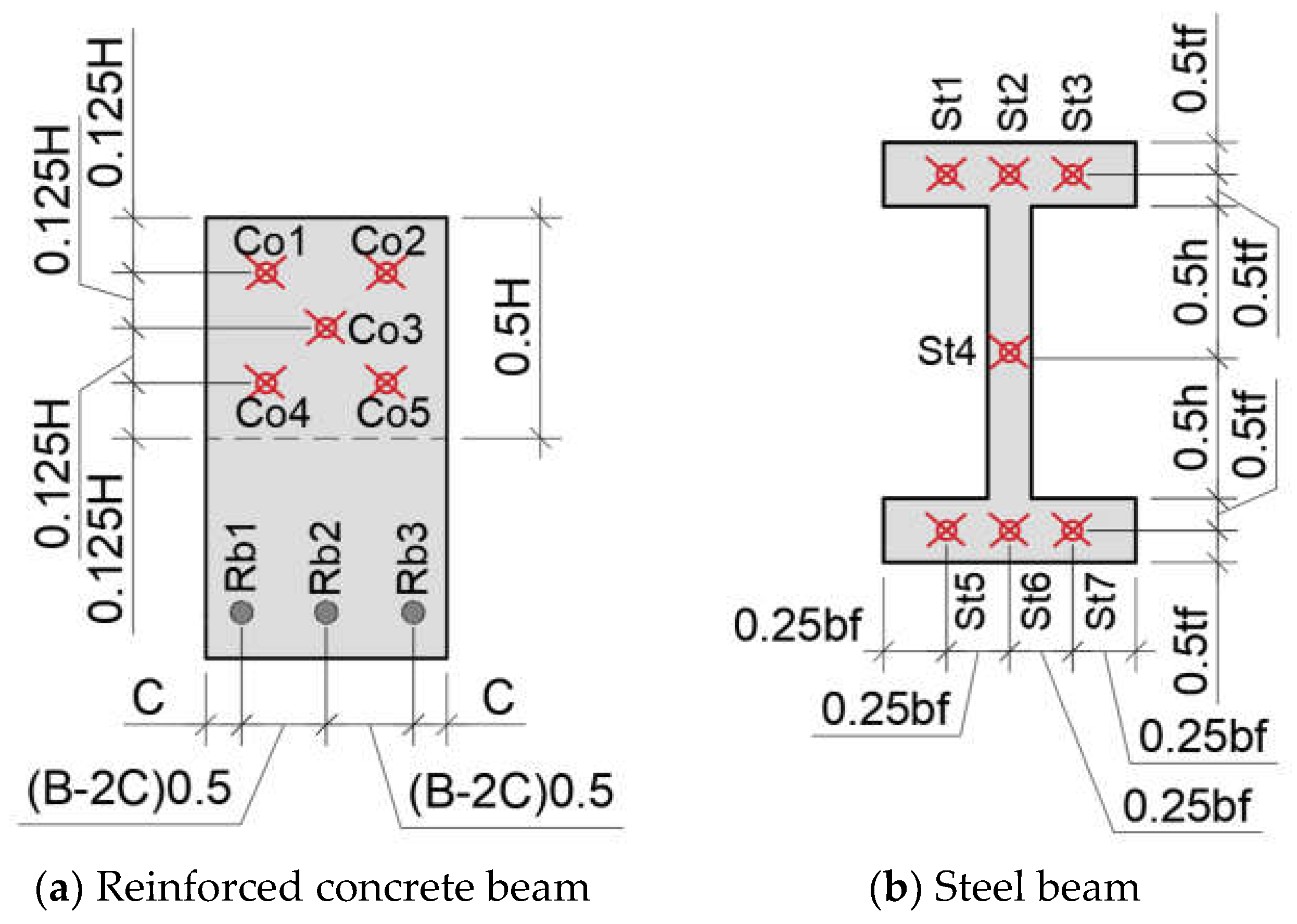
2.3. Control Points
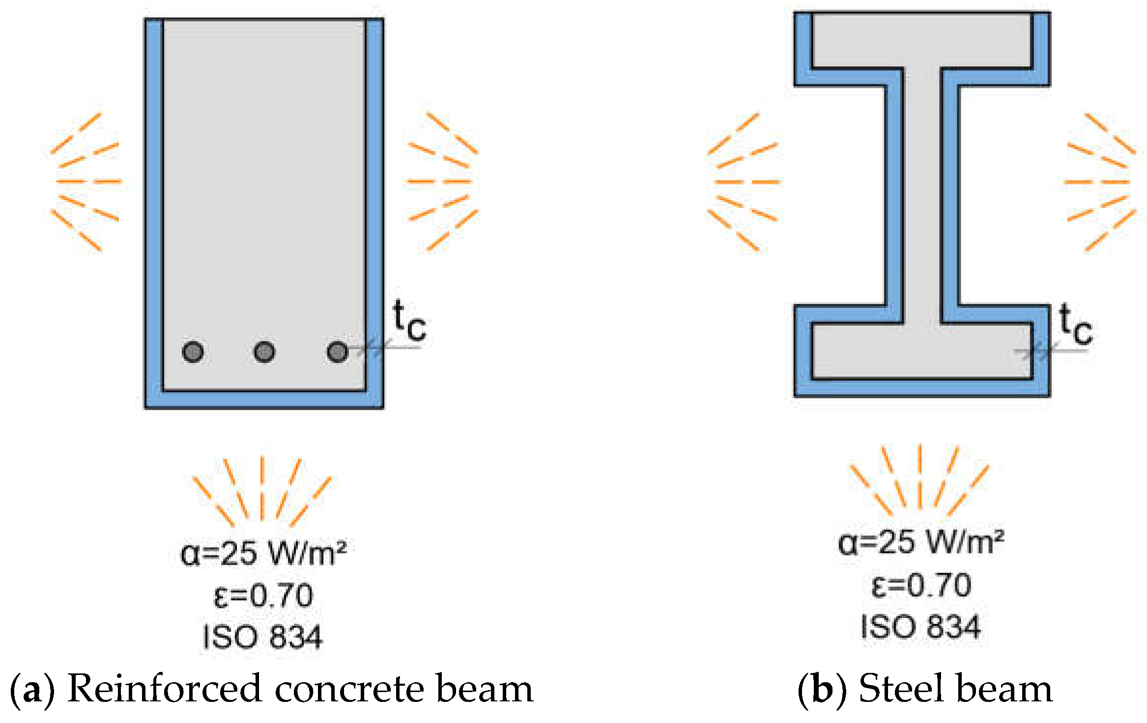
2.4. Finite Element Modeling
3. Results
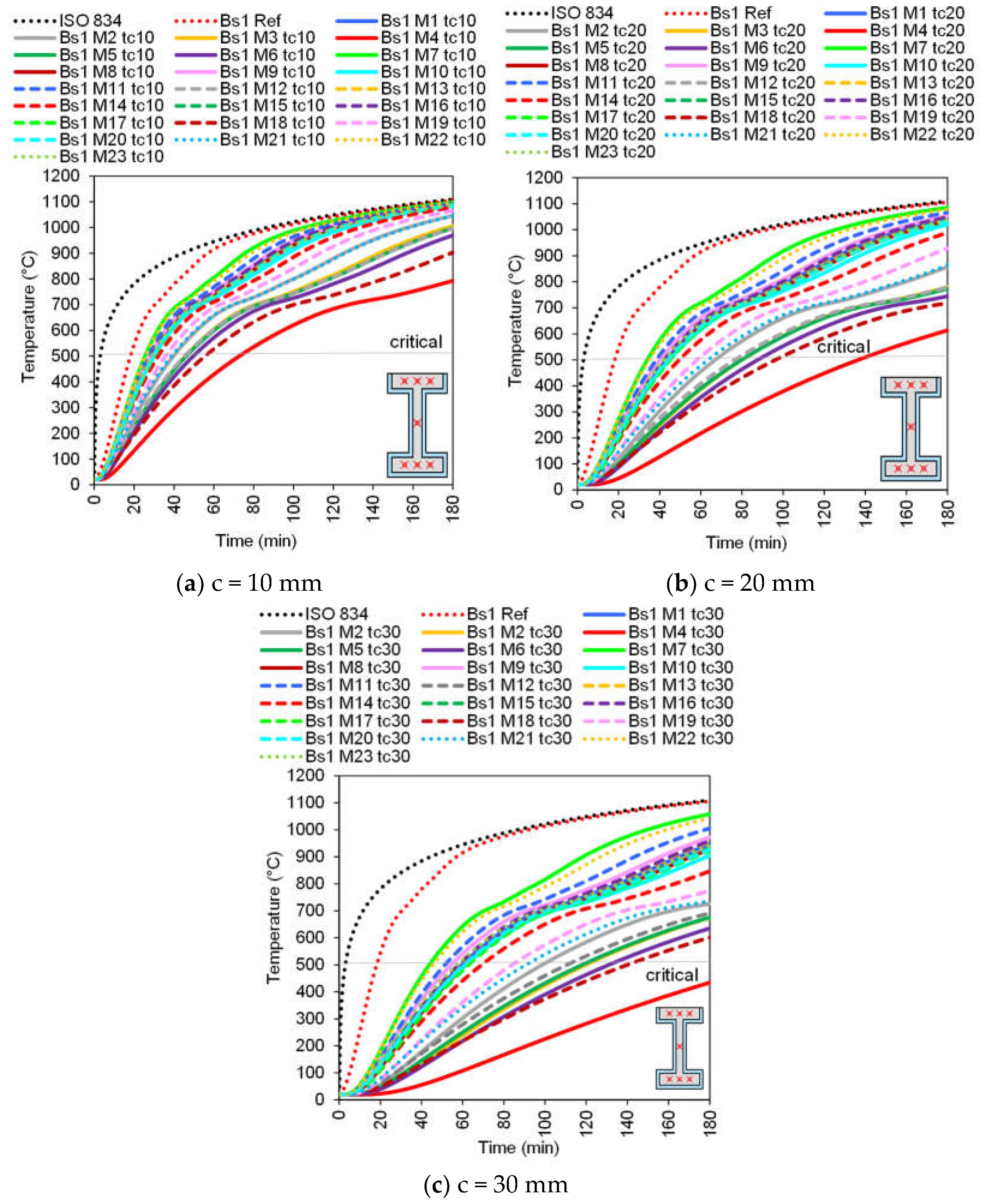
3.1. Bs1 Beams
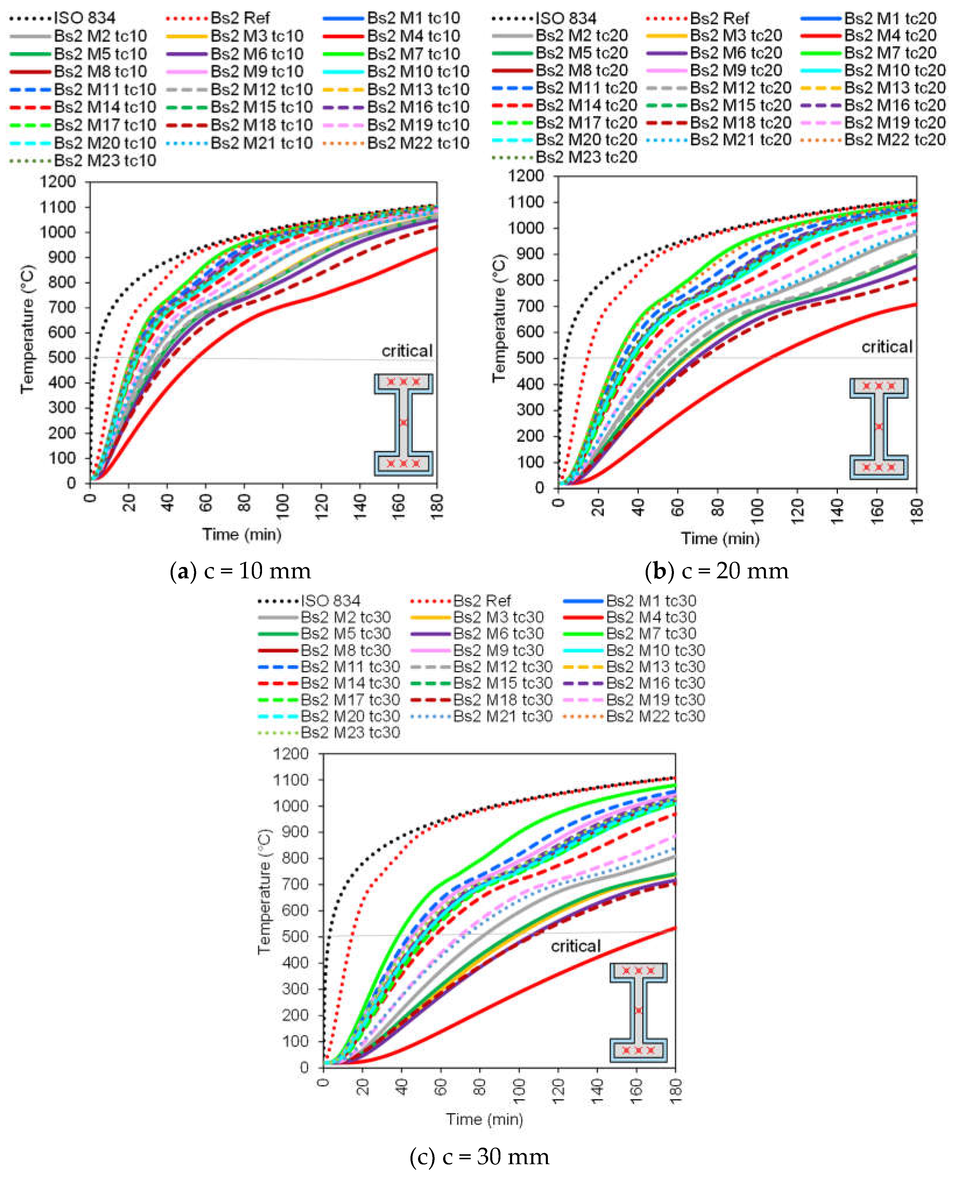
3.2. Bs2 Beams
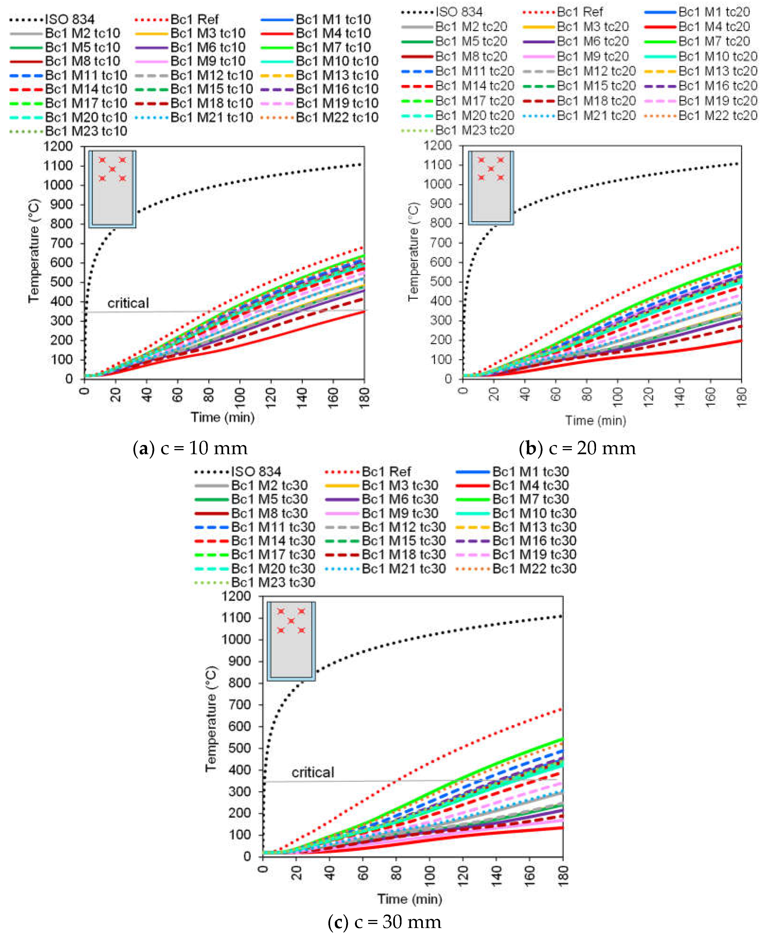
3.3. Bc1 Beams
3.3.1. Average Temperature in the Concrete
3.3.2. Average Temperature in the Reinforcements
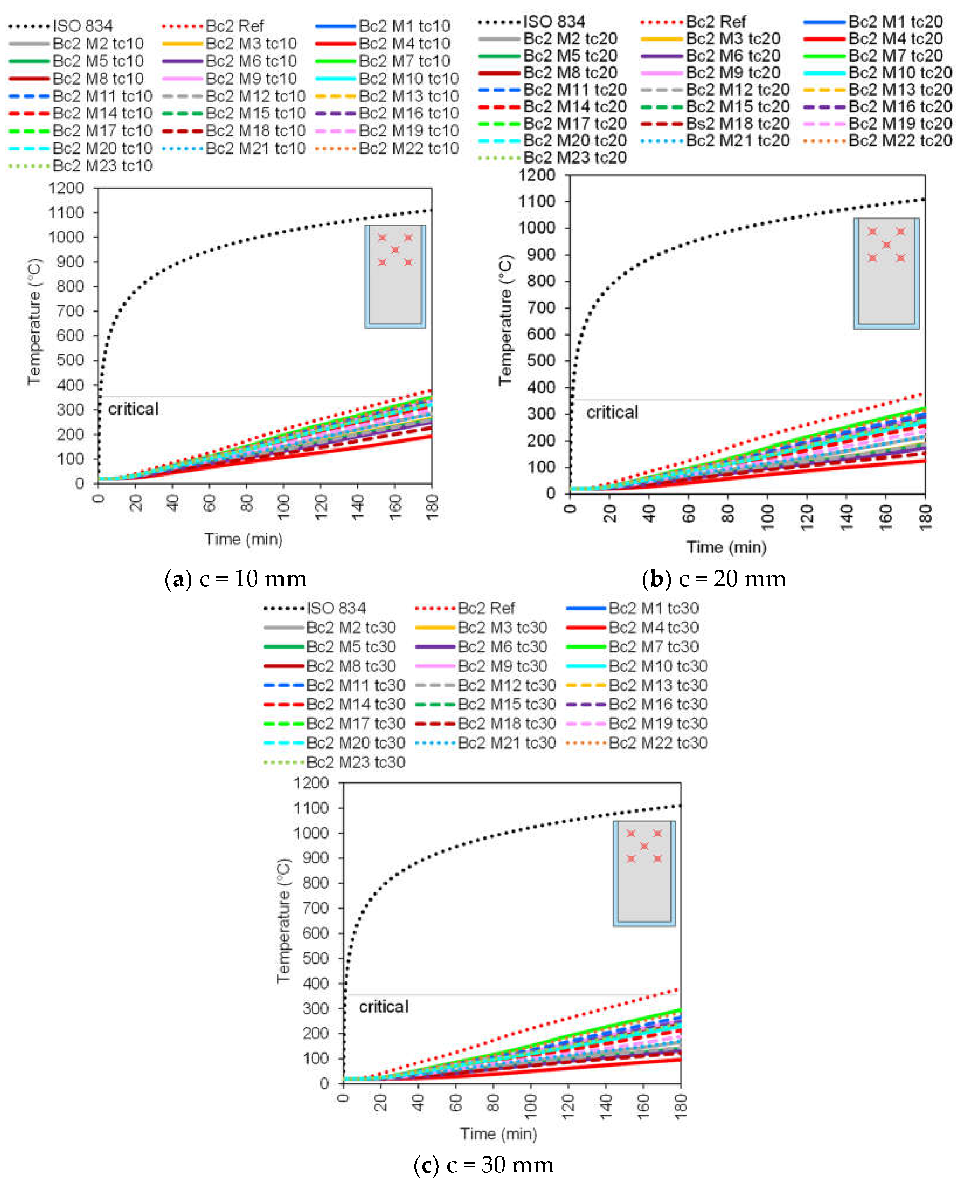
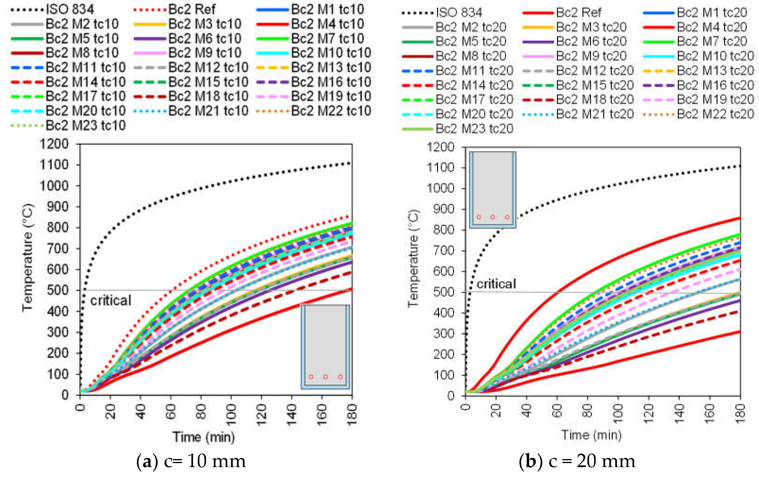
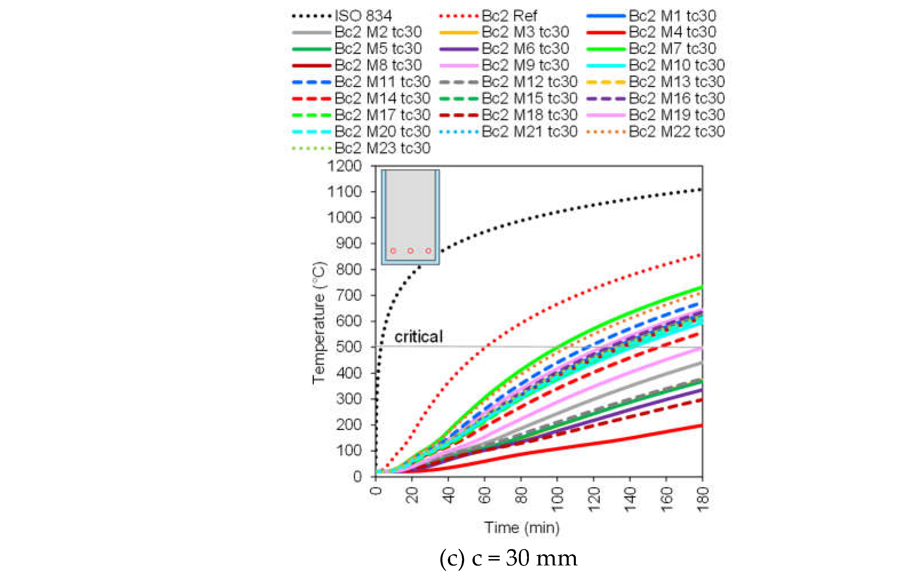
3.4. Bc2 Beams
3.4.1. Average Temperature in the Concrete
3.4.2. Average Temperature in the Reinforcements
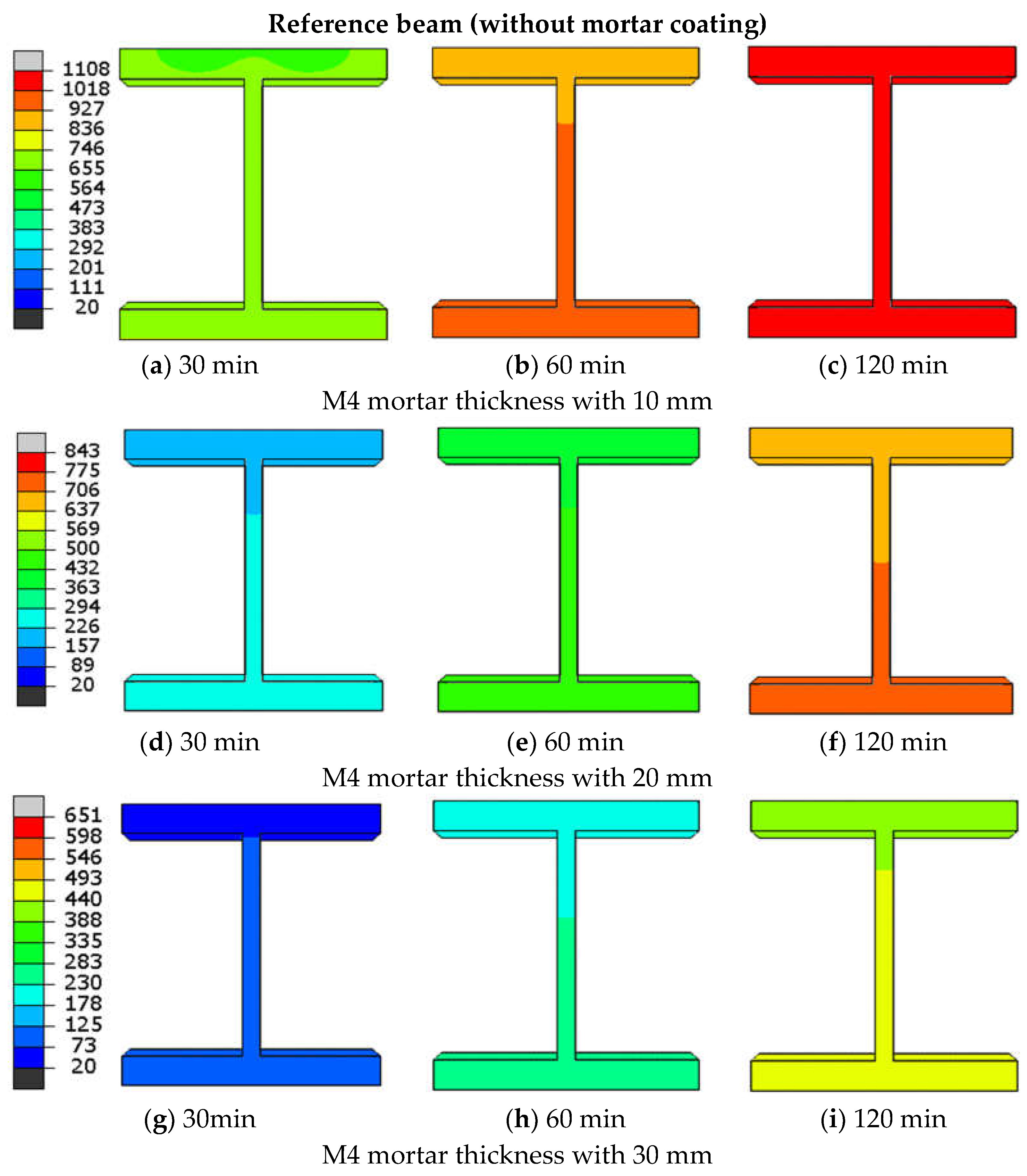
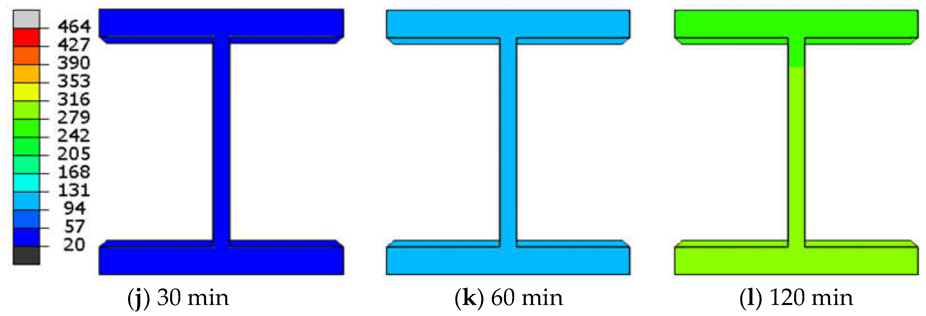
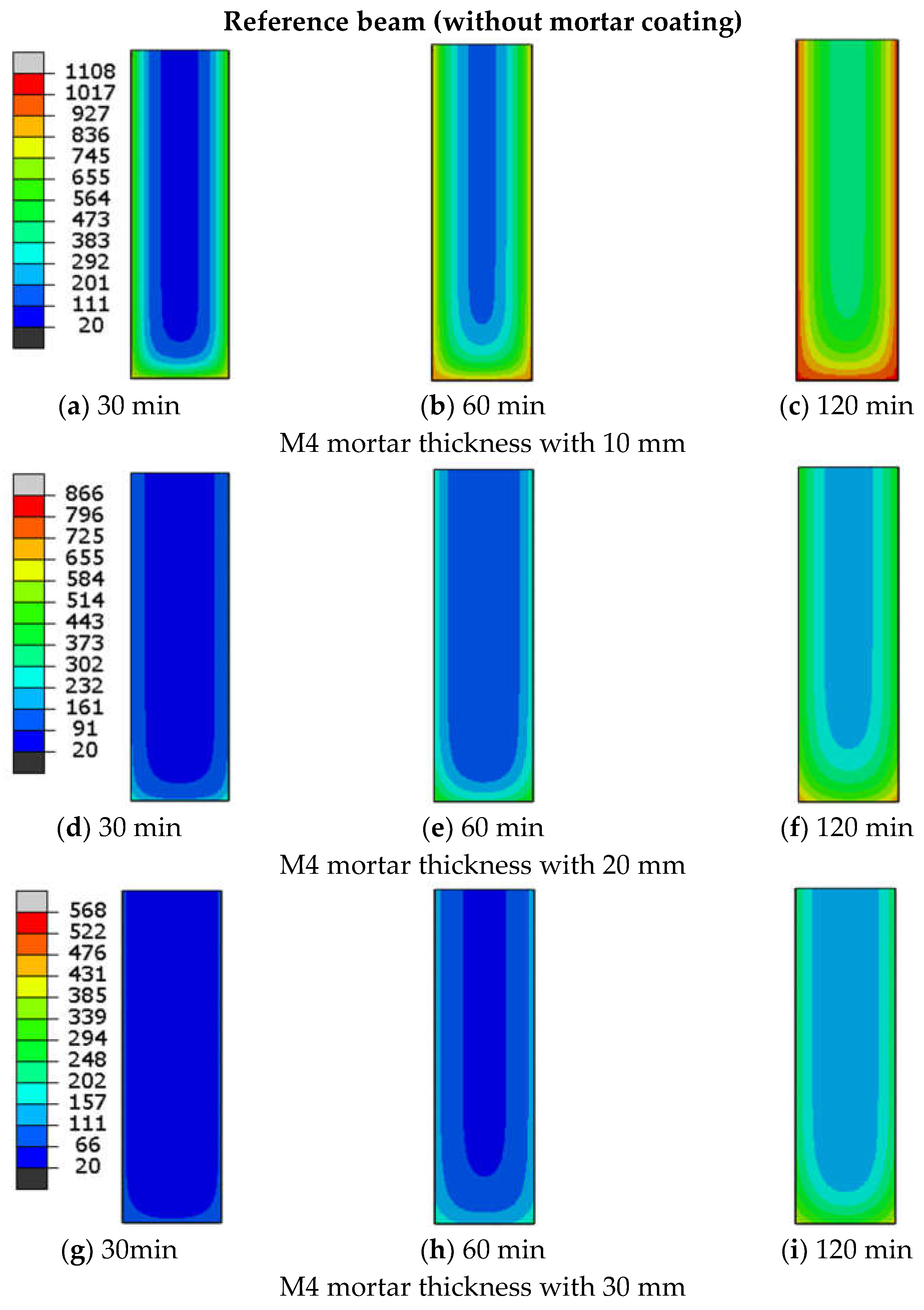
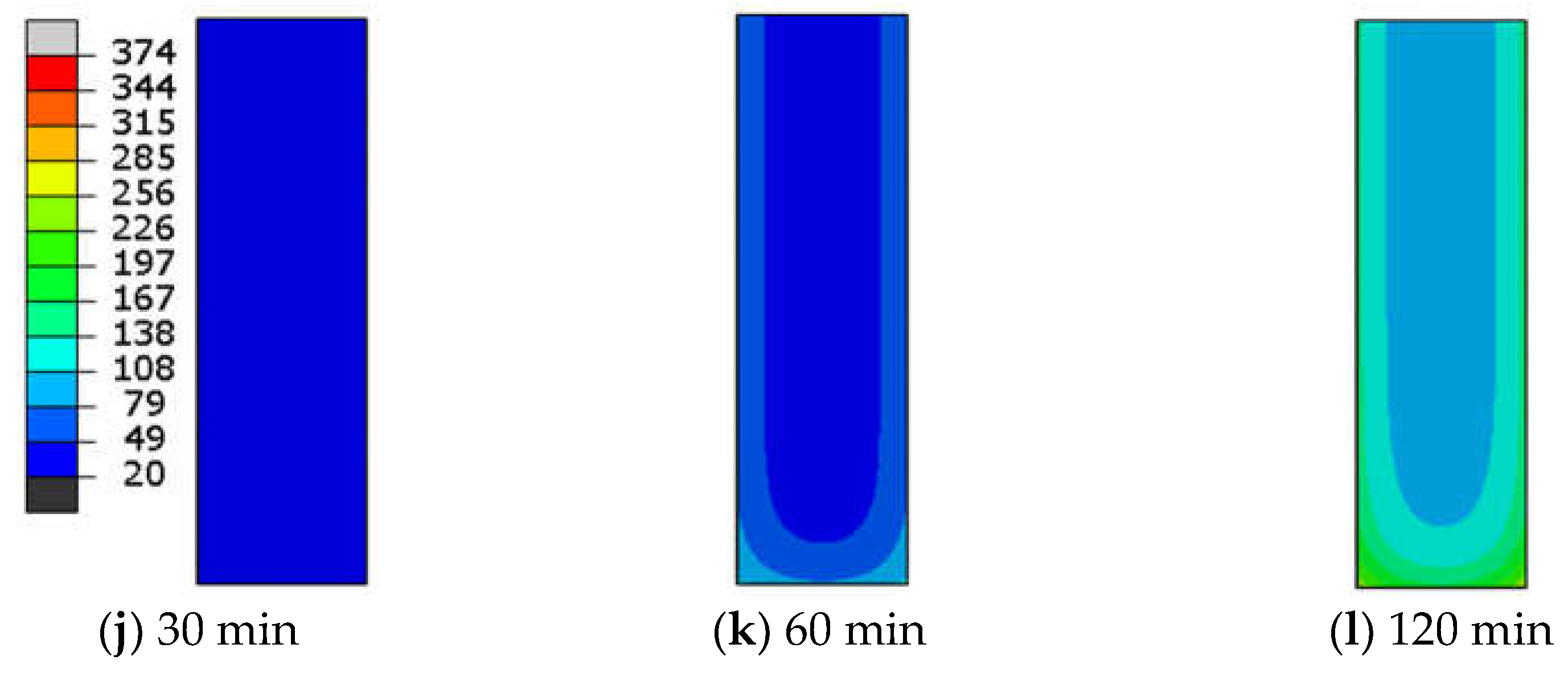
4. Cross-Sectional Temperature Field
5. Critical Discussion of Results
6. Conclusions
- (1).
- Mortars containing glass fiber reinforced polymer (GFRP) as a slag substitute and those incorporating expanded perlite as a sand replacement demonstrated the highest thermal insulation capacity. These mixtures achieved temperature reductions of up to nearly 100% compared to unprotected elements, confirming their superior effectiveness in fire resistance applications.
- (2).
- In contrast, mortars modified with 30% vermiculite or 15% lightweight expanded polyvinyl chloride (PVC) as sand substitutes exhibited the lowest thermal performance, with significantly higher internal temperatures. These results underscore the critical role of material selection in achieving effective thermal protection.
- (3).
- The findings highlight the influence of specific additives on thermal conductivity and overall heat transfer. GFRP powder enhances thermal stability due to the presence of heat-resistant glass fibers, while expanded perlite improves insulation through its highly porous structure, which limits thermal conductivity.
- (4).
- The specific heat was identified as a gap in all the experimental studies reviewed in the literature. Therefore, it is recommended that future experimental research include the measurement of specific heat when conducting thermal analyses of these mortars.
Author Contributions
Funding
Institutional Review Board Statement
Informed Consent Statement
Data Availability Statement
Conflicts of Interest
Appendix A
| Mortar Name | Cement (Kg/m3) | Fayalite Slag (Kg/m3) | Blast Furnace Slag (Kg/m3) | Ladle Slag (Kg/m3) | Fly Ash (Kg/m3) | Slag (Kg/m3) | Sand (Kg/m3) | RV (Kg/m3) | PCM impregnated sepiolite (Kg/m3) | RCB (Kg/m3) | OSW (Kg/m3) | FSA (Kg/m3) | MPCM (Kg/m3) | GFRP (Kg/m3) | EP (Kg/m3) | RP (Kg/m3) | VSS (Kg/m3) | EPVC (Kg/m3) | Water (Kg/m3) | SH (Kg/m3) | SS (Kg/m3) | w/b | Alkali activator (ml) | NA+ (Kg/m3) | SP (%) |
| M1 | 480 | - | - | - | - | - | 1440 | - | - | - | - | - | - | - | - | - | - | - | 288 | - | - | 0.6 | - | - | - |
| M2 | 384 | - | - | - | 76.8 | - | 1440 | - | - | - | - | - | - | 19.2 | - | - | - | - | 276 | - | - | 0.6 | 150 | - | - |
| M3 | - | - | - | - | 76.8 | 384 | 1440 | - | - | - | - | - | - | 19.2 | - | - | - | - | 230 | - | - | 0.5 | 150 | - | - |
| M4 | - | - | - | - | - | 288 | 1440 | - | - | - | - | - | - | 192 | - | - | - | - | 173 | - | - | 0.6 | 150 | - | - |
| M5 | 288 | - | - | - | - | - | 1440 | - | - | - | - | - | - | 192 | - | - | - | - | 173 | - | - | 0.6 | - | - | - |
| M6 | 230 | - | - | - | 57.6 | - | 1440 | - | - | - | - | - | - | 192 | - | - | - | - | 173 | - | - | 0.6 | - | - | - |
| M7 | 520 * | - | - | - | - | - | 1138 ** | 650 | - | - | - | - | - | - | - | - | - | - | 260 | - | - | 0.5 | - | - | - |
| M8 | 520 * | - | - | - | - | - | - | 193 | - | - | - | - | - | - | - | - | - | - | 260 | - | - | 0.5 | - | - | - |
| M9 | 750 | - | - | - | - | - | 1080 | - | 270 | - | - | - | - | - | - | - | - | - | 550 | - | - | 0.7 | - | - | - |
| M10 | 750 | - | - | - | - | - | 810 | - | 540 | - | - | - | - | - | - | - | - | - | 900 | - | - | 1.2 | - | - | - |
| M11 | 520 | - | - | - | - | - | 1138 | - | - | 197 | - | - | - | - | - | - | - | - | 260 | - | - | 0.5 | - | - | - |
| M12 | 520 | - | - | - | - | - | - | - | - | 657 | - | - | - | - | - | - | - | - | 260 | - | - | 0.5 | - | - | - |
| M13 | 450 | - | - | - | - | - | 1282 | - | - | - | 68 | - | - | - | - | - | - | - | 258 | - | - | 0.6 | - | - | - |
| M14 | 450 | - | - | - | - | - | 1147 | - | - | - | 203 | - | - | - | - | - | - | - | 325 | - | - | 0.7 | - | - | - |
| M15 | 645 | - | - | - | - | - | 1290 | - | - | - | - | - | 129 | - | - | - | - | - | 355 | - | - | 0.6 | - | - | - |
| M16 | 488.8 | - | - | - | - | - | 1466.6 | - | - | - | - | - | 97.6 | - | - | - | - | - | 298 | - | - | 0.6 | - | - | - |
| M17 | 389.8 | - | - | - | - | - | 1559.2 | - | - | - | - | - | 77.9 | - | - | - | - | - | 265 | - | - | 0.7 | - | - | - |
| M18 | - | - | - | - | 450 | - | - | - | - | - | - | - | - | - | - | - | - | - | 130 | - | - | 0.3 | - | 45 | - |
| M19 | - | - | - | - | 450 | - | - | - | - | - | - | - | - | - | 100 | - | - | - | 130 | - | - | 0.3 | - | 45 | - |
| M20 | 500 | - | - | - | - | - | 950 | - | - | - | - | - | - | - | - | - | 50 | - | 250 | - | - | 0.5 | - | - | - |
| M21 | 500 | - | - | - | - | - | 800 | - | - | - | - | - | - | - | - | - | 200 | - | 250 | - | - | 0.5 | - | - | - |
| M22 | 450 | - | - | - | - | - | 1148 *** | - | - | - | - | - | - | - | - | - | - | 26.9 | 225 | - | - | 0.5 | - | - | 0.9 |
| M23 | 450 | - | - | - | - | - | 337.5 *** | - | - | - | - | - | - | - | - | - | - | 134.7 | 225 | - | - | 0.5 | - | - | 0.45 |
| * CSA cement; ** Silica Sand; *** 60% quarry sand and 40% sea sand. | |||||||||||||||||||||||||
References
- ISO 23932; Fire Safety Engineering—General Principles. International Organization for Standardization: Geneva, Switzerland, 2018; Volume 1, pp. 1–26.
- ISO 834; Fire-Resistance Tests—Elements of Building Construction. International Organization for Standardization: Geneva, Switzerland, 1999; Volume 1, pp. 1–25.
- Rong, X.; Xu, W.; Zhang, T.; Zhang, J. Mechanical and thermal properties of insulated mortar incorporated with GFRP powder. Constr. Build. Mater. 2024, 416, 135259. [Google Scholar] [CrossRef]
- Tchekwagep, J.J.K.; Yang, F.; Wang, S.; Zhao, P.; Huang, S.; Yang, C.; Cheng, X. Chinese raw vermiculite: A potential additive for improving the thermal properties of calcium sulfoaluminate cement-blended mortars for applications in hot regions. J. Build. Eng. 2024, 92, 109723. [Google Scholar] [CrossRef]
- Topçu, İ.B.; Bayram, M.; Ustaoğlu, A.; Hekimoğlu, G.; Erdoğmuş, E.; Sarı, A.; Gencel, O.; Ozbakkaloglu, T. Innovative cementitious mortar incorporated with sepiolite based shape-stable phase change material for thermal controlling of buildings. Constr. Build. Mater. 2024, 426, 136124. [Google Scholar] [CrossRef]
- Zhao, J.; Huang, G.; Guo, Y.; Gupta, R.; Liu, W.V. Developing thermal insulation cement-based mortars using recycled carbon black derived from scrapped off-the-road tires. Constr. Build. Mater. 2023, 393, 132043. [Google Scholar] [CrossRef]
- EL boukhari, M.; Merroun, O.; Maalouf, C.; Bogard, F.; Kissi, B. Enhancing mechanical and thermal properties of sustainable cement mortar through incorporation of olive solid waste aggregates. Mater. Today Proc. 2023. [Google Scholar] [CrossRef]
- Adediran, A.; Yliniemi, J.; Moukannaa, S.; Ramteke, D.; Perumal, P.; Illikainen, M. Enhancing the thermal stability of alkali-activated Fe-rich fayalite slag-based mortars by incorporating ladle and blast furnace slags: Physical, mechanical and structural changes. Cem. Concr. Res. 2023, 166, 107098. [Google Scholar] [CrossRef]
- Asadi, I.; Ji, G.; Steiner, G. Impact of microencapsulated phase change materials (PCMs) on the thermal and mechanical performance of cement mortar. Dev. Built Environ. 2025, 21, 100594. [Google Scholar] [CrossRef]
- Karakaş, H.; İlKentapar, S.; Durak, U.; Örklemez, E.; Özuzun, S.; Karahan, O.; Atiş, C.D. Properties of fly ash-based lightweight-geopolymer mortars containing perlite aggregates: Mechanical, microstructure, and thermal conductivity coefficient. Constr. Build. Mater. 2023, 362, 129717. [Google Scholar] [CrossRef]
- Salem, T.; Fois, M.; Omikrine-Metalssi, O.; Manuel, R.; Fen-Chong, T. Thermal and mechanical performances of cement-based mortars reinforced with vegetable synthetic sponge wastes and silica fume. Constr. Build. Mater. 2020, 264, 120213. [Google Scholar] [CrossRef]
- Latroch, N.; Benosman, A.S.; Bouhamou, N.E.; Senhadji, Y.; Mouli, M. Physico-mechanical and thermal properties of composite mortars containing lightweight aggregates of expanded polyvinyl chloride. Constr. Build. Mater. 2018, 175, 77–87. [Google Scholar] [CrossRef]
- Abaqus Abaqus Analysis User’s Guide. 2016, Simulia. Available online: https://www.3ds.com/products/simulia/abaqus (accessed on 1 June 2025).
- EN 1992-1.2; Eurocode 2: Design of Concrete Structures—Part 1-2: General Rules—Structural Fire Design. European Committee for Standardization: Brussels, Belgium, 2004.
- Banerji, S.; Kodur, V. Numerical model for tracing the response of Ultra-High performance concrete beams exposed to fire. Fire Mater. 2023, 47, 322–340. [Google Scholar] [CrossRef]
- ASTM E 119; Standard Test Methods for Fire Tests of Building Construction and Materials. ASTM International: Geneva, Switzerland, 2018.
- Bolina, F.L.; Schallenberger, M.; Carvalho, H. Experimental and numerical evaluation of RC ribbed slabs in fire conditions. Structures 2023, 51, 747–759. [Google Scholar] [CrossRef]
- Bolina, F.L.; Poleto, G.; Carvalho, H. Proposition of parametric data for UHPC at high temperatures. J. Build. Eng. 2023, 76, 107222. [Google Scholar] [CrossRef]
- Bolina, F.L.; Rodrigues, J.P.C. Finite element analysis criteria for composite steel decking concrete slabs subjected to fire. Fire Saf. J. 2023, 139, 103818. [Google Scholar] [CrossRef]
- Kodur, V.K.R.; Phan, L. Critical factors governing the fire performance of high strength concrete systems. Fire Saf. J. 2007, 42, 482–488. [Google Scholar] [CrossRef]
- Yeo, H.; Cho, K.S.; Cho, B.Y.; An, J.H.; Kim, H.J. A Study on Relations Between Section Shape Factor and Temperature History of Steel of Composite Beam Subjected to Standard Fire under Same Thickness Condition of Spray-Type Fire Resistant Materials. Adv. Mat. Res. 2013, 671–674, 912–920. [Google Scholar] [CrossRef]
- Shaoqing, L.; Lik-ho, T.; Hongqiang, M.; Jianping, G.; Chao, W. Pozzolanic Analysis of GFRP Powder from Retired Wind Turbine Blades as Supplementary Cementitious Material. J. Mater. Civ. Eng. 2025, 37, 04024543. [Google Scholar] [CrossRef]
- Zhang, M.; Qiu, X.; Shen, S.; Wang, L.; Zang, Y. Mechanical and Thermal Insulation Properties of rGFRP Fiber-Reinforced Lightweight Fly-Ash-Slag-Based Geopolymer Mortar. Sustainability 2023, 15, 7200. [Google Scholar] [CrossRef]
- Oktay, H.; Yumrutaş, R.; Akpolat, A. Mechanical and thermophysical properties of lightweight aggregate concretes. Constr. Build. Mater. 2015, 96, 217–225. [Google Scholar] [CrossRef]
- Demirboğa, R.; Gül, R. The effects of expanded perlite aggregate, silica fume and fly ash on the thermal conductivity of lightweight concrete. Cem. Concr. Res. 2003, 33, 723–727. [Google Scholar] [CrossRef]
- Öztürk, M. Elevated Temperature Resistance of Mortars Including Ground Granulated Blast Furnace Slag, Fly ash and Silica Fume. Osman. Korkut Ata Üniv. Fen Bilim. Enst. Derg. 2022, 5, 143–153. [Google Scholar] [CrossRef]
- Sarkar, A.; Bose, S. Exploring impact of opaque building envelope components on thermal and energy performance of houses in lower western Himalayans for optimal selection. J. Build. Eng. 2016, 7, 170–182. [Google Scholar] [CrossRef]
- Al-Salem, S.M.; Lettieri, P.; Baeyens, J. Recycling and recovery routes of plastic solid waste (PSW): A review. Waste Manag. 2009, 29, 2625–2643. [Google Scholar] [CrossRef] [PubMed]
- Albite-Ortega, J.; Sánchez-Valdes, S.; Ramírez-Vargas, E.; Medellín-Rodríguez, F.J.; Devalle, L.F.R.; Rodriguez-Fernandez, O.S.; Rivera-Salinas, J.E.; Martínez-Colunga, J.G.; Da-Silva, L.; Morales-Cepeda, A.B.; et al. Influence of ammonium polyphosphate-modified polypropylene on flammability characteristics of polypropylene keratin and chitosan sustainable composites. Fire Mater. 2023, 47, 170–181. [Google Scholar] [CrossRef]
- Bolina, F.L.; Henn, A.S. Eco-Friendly Reinforced Concrete Beams Exposed to Standardized Fire: A Thermal Finite Element Analysis. Sustainability 2025, 17, 2951. [Google Scholar] [CrossRef]
- Bolina, F.L.; Fachinelli, E.G.; Rodrigues, J.P.C. Analysis of building structures subjected to electric vehicle fires. J. Build. Eng. 2025, 107, 112769. [Google Scholar] [CrossRef]
- Bolina, F.L.; Henn, A.S.; Lago, B.D. Simplified Design Procedure for RC Ribbed Slabs in Fire Based on Experimental and Numerical Thermal Analysis. Buildings 2025, 15, 1631. [Google Scholar] [CrossRef]


| Mortar Name | Description | Reference |
|---|---|---|
| M1 | Conventional mortar with cement and sand | Rong et al., 2024 [3] |
| M2 | 4% Glass Fiber Reinforced Polymers Powder and 16% Fly Ash cement replacement | |
| M3 | 4% Glass Fiber Reinforced Polymers Powder and 16% Fly Ash Slag replacement | |
| M4 | 40% Glass Fiber Reinforced Polymers Powder Slag replacement | |
| M5 | 40% Glass Fiber Reinforced Polymers Powder Cement replacement | |
| M6 | 40% Glass Fiber Reinforced Polymers Powder and 20% Fly Ash cement replacement | |
| M7 | Raw Vermiculite 30% sand replacement | Tchekwagep et al., 2024 [4] |
| M8 | Raw Vermiculite 100% sand replacement | |
| M9 | Phase Change Material 20% sand replacement | Topçu et al., 2024 [5] |
| M10 | Phase Change Material 40% sand replacement | |
| M11 | Carbon Black 30% sand replacement | Zhao et al., 2023 [6] |
| M12 | Carbon Black 100% sand replacement | |
| M13 | Olive Solid Waste 5% sand replacement | EL boukhari et al., 2023 [7] |
| M14 | Olive Solid Waste 15% sand replacement | |
| M15 | Microencapsulated Phase Change Materials 20% cement weight addition | Asadi et al., 2025 [9] |
| M16 | Microencapsulated Phase Change Materials 20% cement weight addition | |
| M17 | Microencapsulated Phase Change Materials 20% cement weight addition | |
| M18 | Expanded Perlite 100% Sand replacement | Karakaş et al., 2023 [10] |
| M19 | Raw Perlite 100% Sand replacement | |
| M20 | Vegetable Synthetic Sponge 5% sand replacement | Salem et al. 2020 [11] |
| M21 | Vegetable Synthetic Sponge 20% sand replacement | |
| M22 | lightweight aggregates of Expanded Polyvinyl Chloride 15% sand replacement | Latroch et al. 2018 [12] |
| M23 | lightweight aggregates of Expanded Polyvinyl Chloride 75% sand replacement |
| Mortar Name | Thermal Conductivity (W/mK) | Density (Kg/m3) |
|---|---|---|
| M1 | 0.86 | 1900 |
| M2 | 0.39 | 1850 |
| M3 | 0.3 | 1870 |
| M4 | 0.14 | 1700 |
| M5 | 0.28 | 1500 |
| M6 | 0.25 | 1600 |
| M7 | 1.75 | 2100 |
| M8 | 0.8 | 1830 |
| M9 | 0.891 | 1471 |
| M10 | 0.674 | 1240 |
| M11 | 1.094 | 1779 |
| M12 | 0.272 | 1058 |
| M13 | 0.87 | 1750 |
| M14 | 0.58 | 1375 |
| M15 | 0.8 | 1767.8 |
| M16 | 0.9 | 1894.6 |
| M17 | 0.8 | 1956.9 |
| M18 | 0.19 | 880 |
| M19 | 0.48 | 1760 |
| M20 | 0.769 | 1610 |
| M21 | 0.368 | 1170 |
| M22 | 1.4 | 1750 |
| M23 | 0.76 | 1250 |
| Beam Name | B | H |
|---|---|---|
| Bc1 | 150 mm | 500 mm |
| Bc2 | 250 mm | 500 mm |
| Beam Name | d | h | |||
|---|---|---|---|---|---|
| Bs1 | 229 | 210 | 23.7 | 180 | 14.5 |
| Bs2 | 535 | 166 | 16.5 | 502 | 10.3 |
Disclaimer/Publisher’s Note: The statements, opinions and data contained in all publications are solely those of the individual author(s) and contributor(s) and not of MDPI and/or the editor(s). MDPI and/or the editor(s) disclaim responsibility for any injury to people or property resulting from any ideas, methods, instructions or products referred to in the content. |
© 2025 by the authors. Licensee MDPI, Basel, Switzerland. This article is an open access article distributed under the terms and conditions of the Creative Commons Attribution (CC BY) license (https://creativecommons.org/licenses/by/4.0/).
Share and Cite
Bolina, F.L.; Henn, A.S.; Silva, D.B.; Pachla, E.C. Numerical Evaluation of Modified Mortar Coatings for Thermal Protection of Reinforced Concrete and Steel Structures Under Standardized Fire Exposure. Coatings 2025, 15, 806. https://doi.org/10.3390/coatings15070806
Bolina FL, Henn AS, Silva DB, Pachla EC. Numerical Evaluation of Modified Mortar Coatings for Thermal Protection of Reinforced Concrete and Steel Structures Under Standardized Fire Exposure. Coatings. 2025; 15(7):806. https://doi.org/10.3390/coatings15070806
Chicago/Turabian StyleBolina, Fabrício Longhi, Arthur S. Henn, Débora Bretas Silva, and Eduardo Cesar Pachla. 2025. "Numerical Evaluation of Modified Mortar Coatings for Thermal Protection of Reinforced Concrete and Steel Structures Under Standardized Fire Exposure" Coatings 15, no. 7: 806. https://doi.org/10.3390/coatings15070806
APA StyleBolina, F. L., Henn, A. S., Silva, D. B., & Pachla, E. C. (2025). Numerical Evaluation of Modified Mortar Coatings for Thermal Protection of Reinforced Concrete and Steel Structures Under Standardized Fire Exposure. Coatings, 15(7), 806. https://doi.org/10.3390/coatings15070806