
Microstructure, Wear and Corrosion Properties of Inconel 718-CeO2 Composite Coatings


Abstract
1. Introduction
2. Experimental Materials and Methods
2.1. Materials
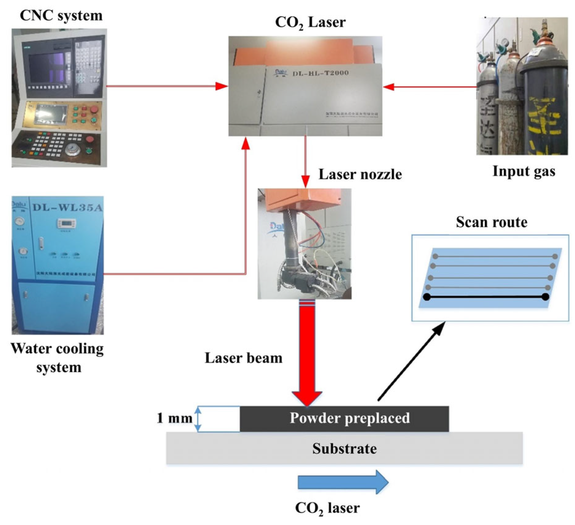
2.2. Experimental Scheme
2.3. Experimental Methods
3. Results
3.1. Phase Analysis
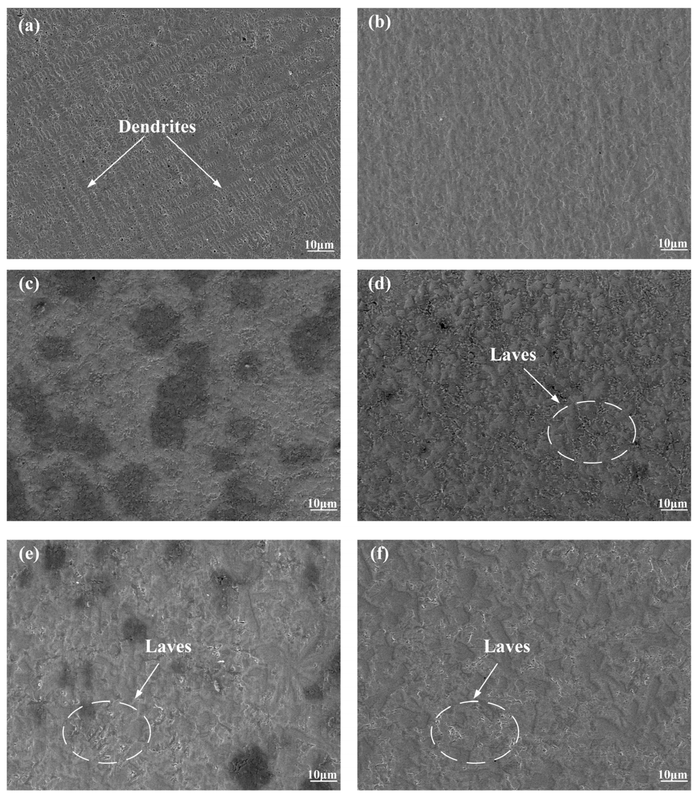
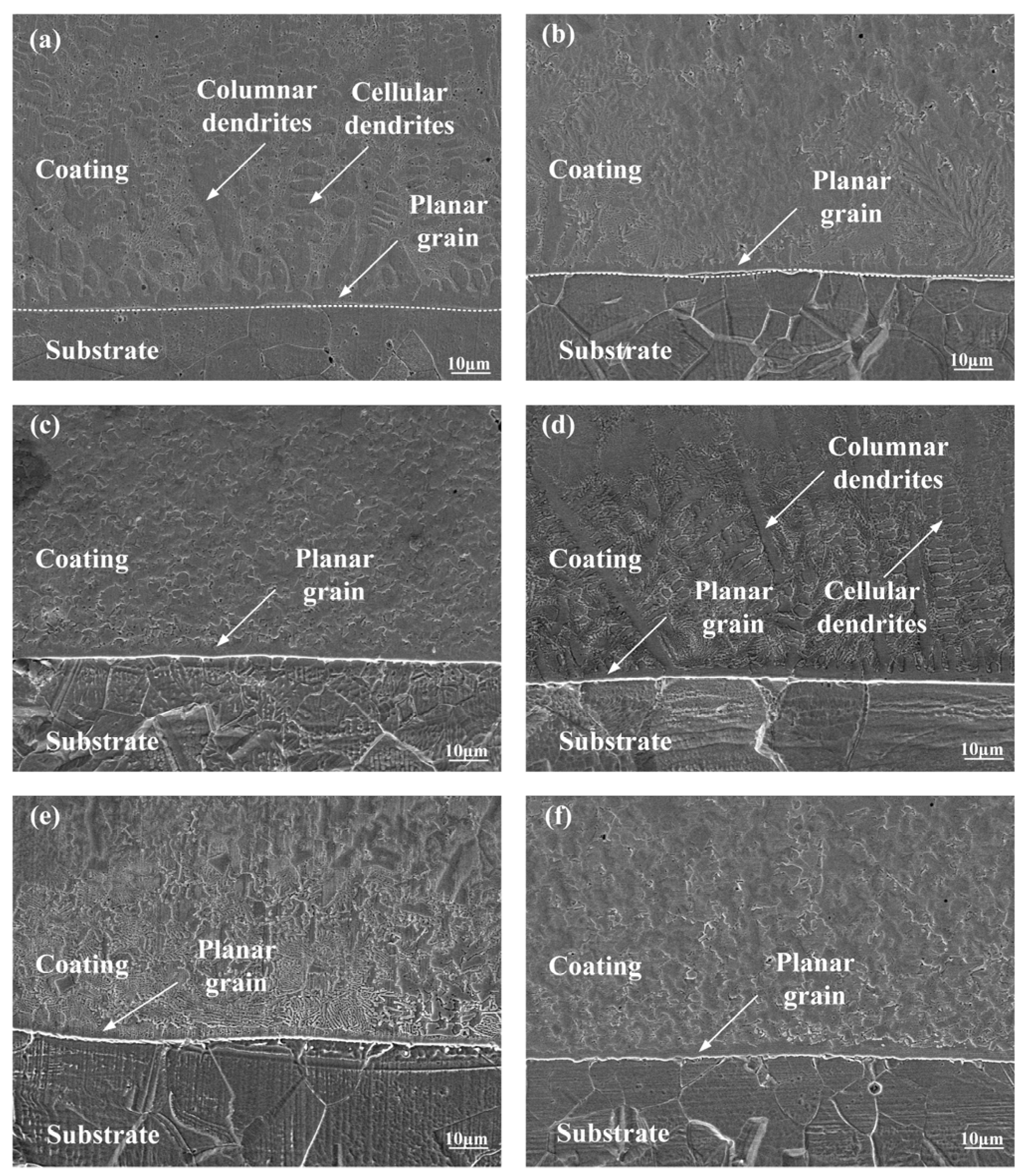
3.2. Microstructure
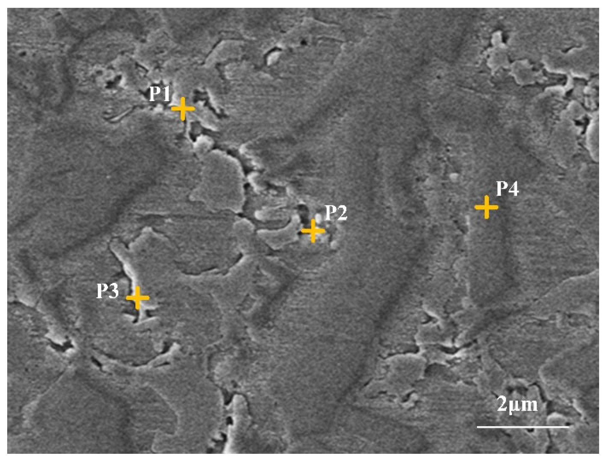
3.3. Elemental Distribution
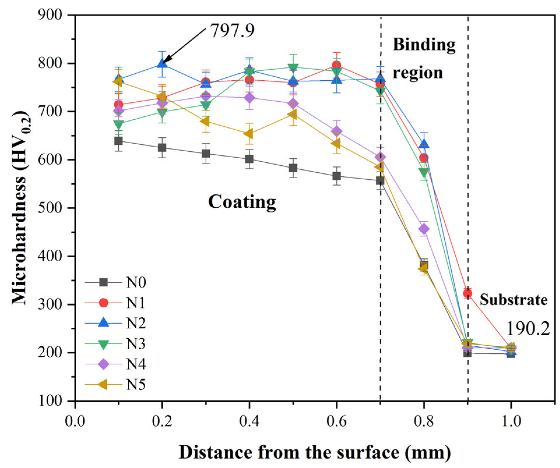
3.4. Microhardness
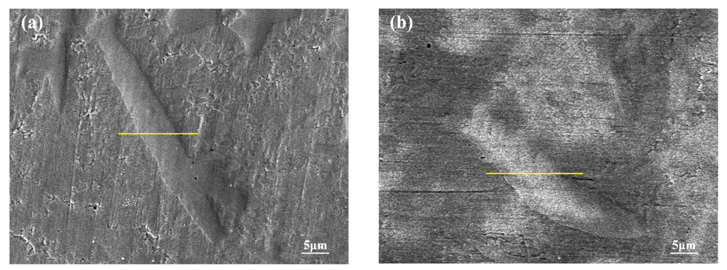
3.5. Friction and Wear
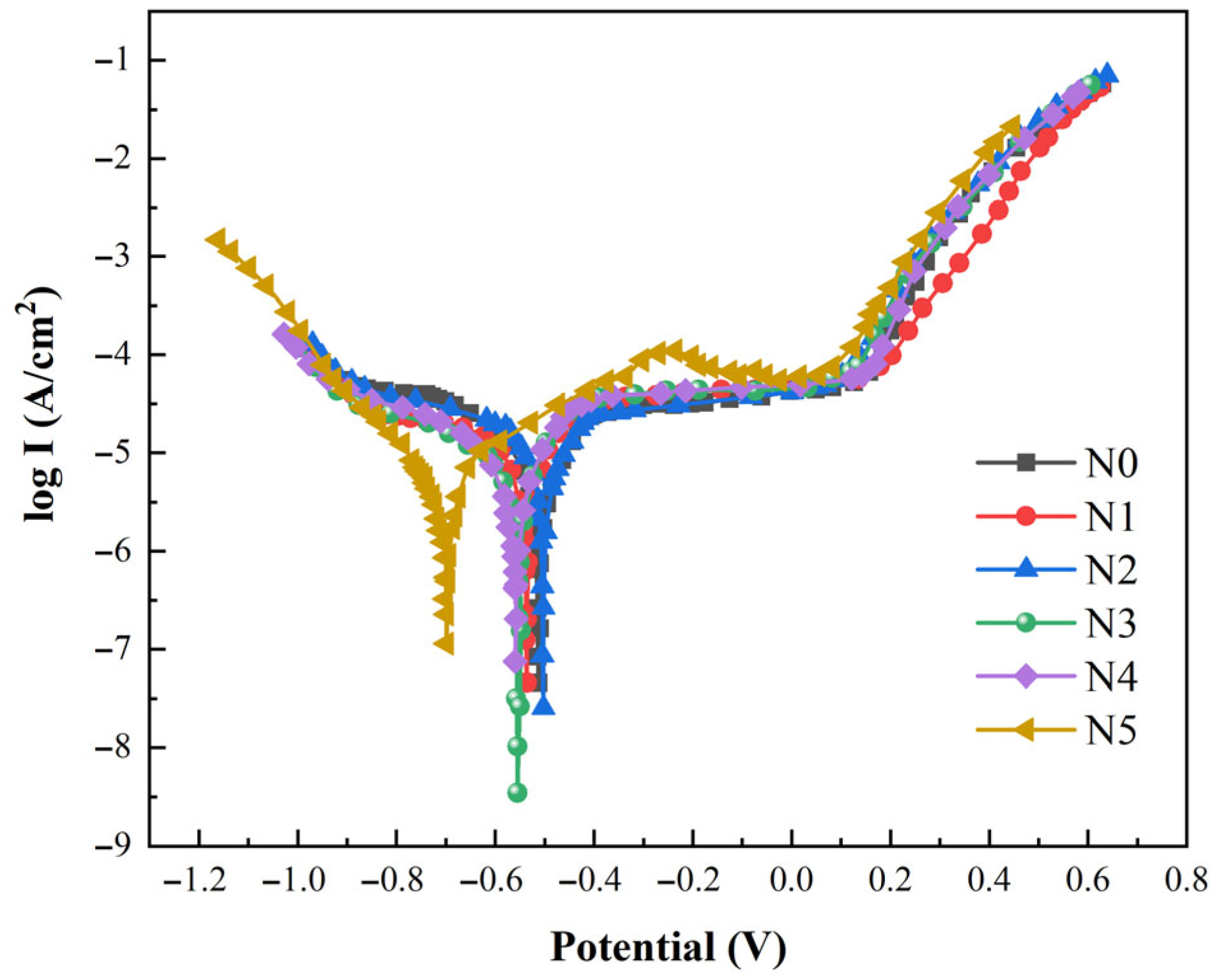
3.6. Electrochemical Corrosion
4. Conclusions
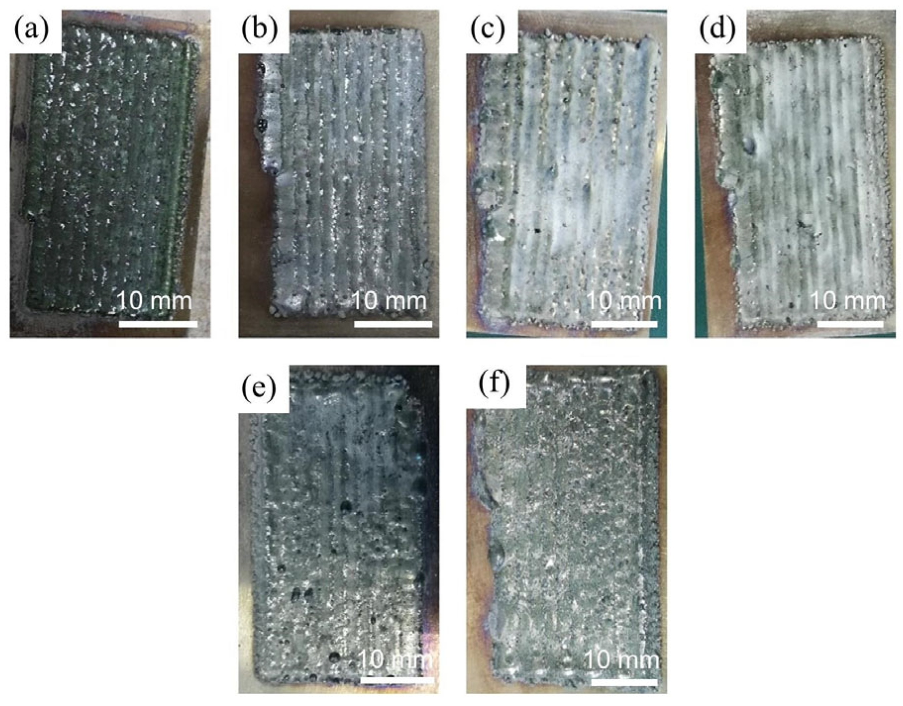
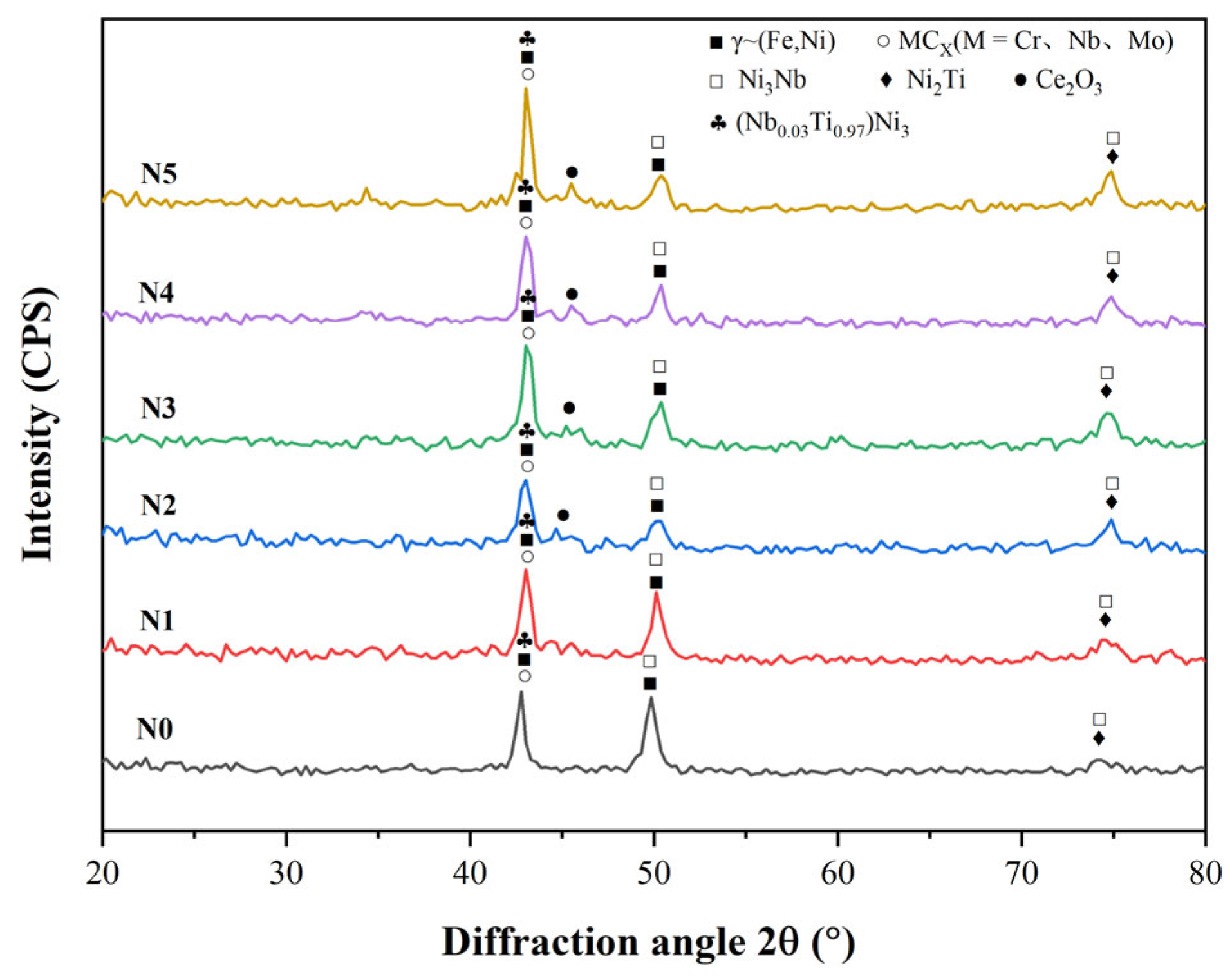
- All six Inconel 718/CeO2 coatings are prepared successfully and have good metallurgical bonding with the 316L substrate. The phases of the N0~N5 coatings are similar, including the γ~(Fe, Ni) solid solution, Ni3Nb, (Nb0.03Ti0.97)Ni3, MCX(M = Cr, Nb, Mo) and others. When the amount of CeO2 particles is greater than 1%, the Ce2O3 phase appears in the N1~N5 coatings. The background region of the N0~N5 coatings is γ~(Fe, Ni) solid solution. The MCX carbides distribute among the γ~(Fe, Ni) solid solution.
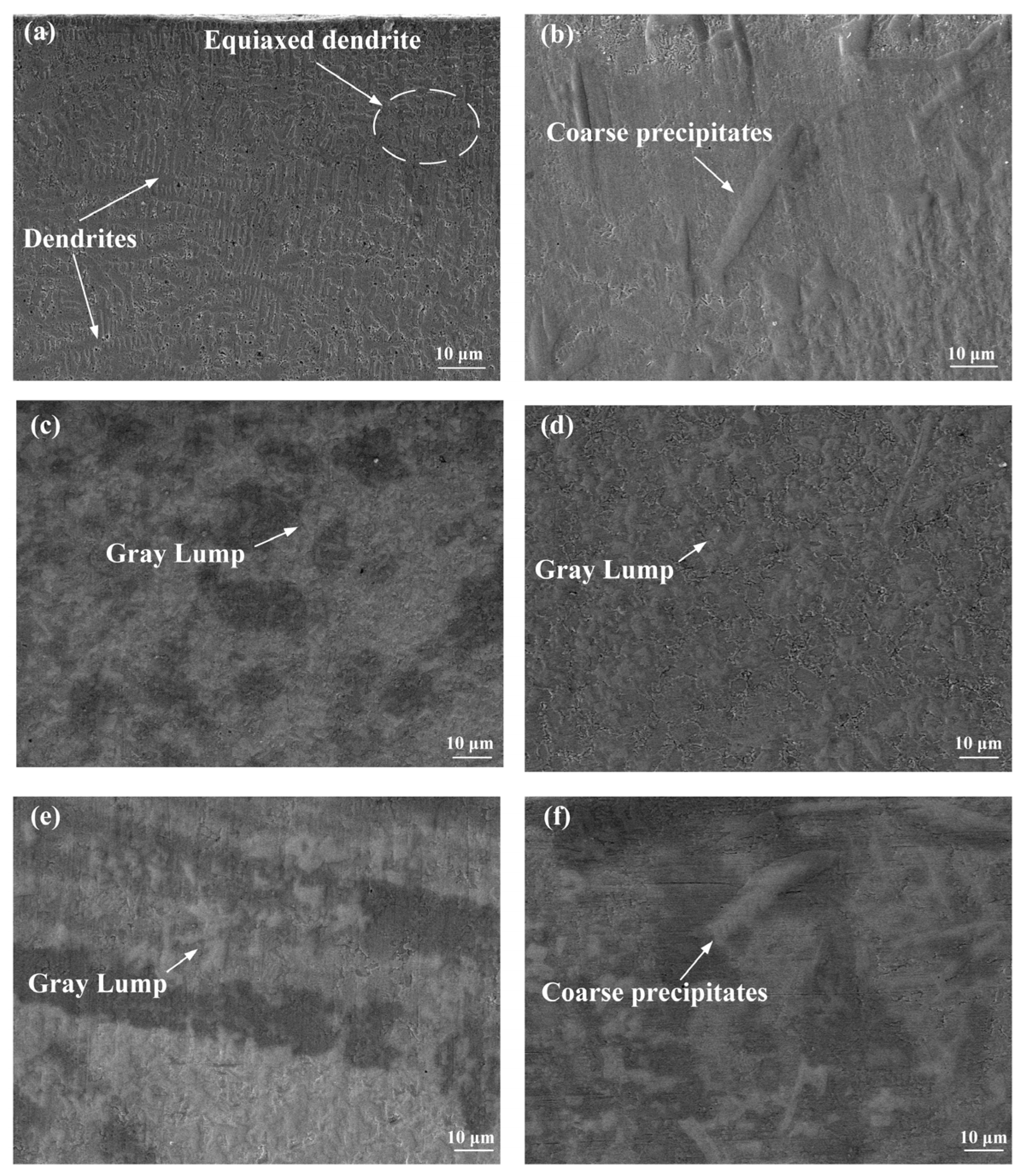
- The values of the average microhardness of the N0~N5 coatings are 604.6, 754.5, 771.6, 741.4, 694.5 and 677.3 HV0.2, respectively. Along with the increase in CeO2, the values of the average microhardness increase first and then decrease. When the amounts of CeO2 are 1% and 2% in the N1 and N2 coatings, the Laves phase decreases. When the amount of CeO2 is more than 3%, some big compounds and Laves appear more than the N2 coating in the coatings. And the formation of Laves phase will consume more Cr, Mo and Nb elements in the coating, which will reduce the number of carbides.
- The wear rates of the N0~N5 coatings are 2.97 × 10⁻⁵, 1.22 × 10⁻⁵, 0.94 × 10⁻⁵, 1.53 × 10⁻⁵, 1.81 × 10⁻⁵ and 2.26 × 10⁻⁵ mm3∙N−1∙min−1, respectively. With the increase in CeO2, the wear rates of the N0~N5 coatings increase first and then decrease. The N2 coating has the lowest wear rate due to the uniform phase distribution. The corrosion potential of the N2 coating is −0.495 V, and the corrosion current density is 2.05 × 10⁻⁴ A∙cm−2. It has the highest corrosion potential and the lowest corrosion current density due to the lower precipitation of the Laves phase and more Cr, Mo and Nb compounds, which shows the better performance of the corrosion resistance. In future studies, it will be beneficial to study a detailed amount of CeO2, such as 1.5%.
Author Contributions
Funding
Institutional Review Board Statement
Informed Consent Statement
Data Availability Statement
Conflicts of Interest
References
- Ding, H.; Yang, T.; Wang, W.; Zhu, Y.; Lin, Q.; Guo, J.; Liu, Q. Optimization and wear behaviors of 316L stainless steel laser cladding on rail material. Wear 2023, 523, 204830. [Google Scholar] [CrossRef]
- Zhao, D.; Long, D.; Niu, T.; Hu, X.; Liu, J. Microstructure and mechanical properties of 316L stainless steel arc additive manufacturing. Mar. Eng. 2002, 44, 14–17+88. [Google Scholar]
- Zhang, Y.; Zhang, X.; Chen, S.; Li, T.; Liu, J.; Wu, M. Effect of phosphoric acid concentration on corrosion resistance and passivation film properties of 316L stainless steel. Chin. J. Corros. Prot. 2022, 42, 819–825. [Google Scholar]
- Tukur, H.; Yonghao, L. Oxidation and deformation behaviours of the 316L stainless-steel weldments in nuclear plants. Int. J. Electrochem. Sci. 2020, 15, 2115–2132. [Google Scholar] [CrossRef]
- ALMisned, G.; Yayla, N.; Albayrak, M.G.; Güler, Ö.; Baykal, D.S.; Alkarrani, H.; Tekin, H.O. Blending effects of boron carbide and lanthanum (III) oxide reinforcements on the structural, physical, mechanical, and radiation shielding properties of 316L-stainless steel composites for nuclear applications. Ann. Nucl. Energy 2025, 221, 111537. [Google Scholar] [CrossRef]
- Li, M.; Zhou, B. Analysis on the failure causes of bearing used in a certain aircraft. Hot Work. Technol. 2019, 48, 256–258. [Google Scholar]
- Yu, P.; Tao, X.; Liu, Z.; Zeng, K.; Jiang, H.; Zhang, Y. Research status and prospect of aircraft gas turbine engine collision. Aero Engines 2023, 49, 1–17. [Google Scholar]
- Davoodi, F.; Ashrafizadeh, F.; Atapour, M.; Akbari-Kharaji, E.; Mokhtari, R. Anticorrosion performance of TiN coating with electroless nickel-phosphorus interlayer on Al 6061 Alloy. Mater. Chem. Phys. 2023, 296, 127170. [Google Scholar] [CrossRef]
- Liu, Y.; Cui, X.; Fang, Y.; Wen, X.; Chen, H.; Jin, G. Research progress on erosion damage and protective coatings of aero engines. China Surf. Eng. 2022, 35, 31–47. [Google Scholar]
- Ertugrul, O.; Enrici, T.M.; Paydas, H.; Saggionetto, E.; Boschini, F.; Mertens, A. Laser cladding of TiC reinforced 316L stainless steel composites: Feedstock powder preparation and microstructural evaluation. Powder Technol. 2020, 375, 384–396. [Google Scholar] [CrossRef]
- Lakkannavar, V.; Yogesha, K.B.; Prasad, C.D.; Phanden, R.K.; Prasad, S.C. Thermal spray coatings on high-temperature oxidation and corrosion applications–a comprehensive review. Results Surf. Interfaces 2024, 16, 100250. [Google Scholar] [CrossRef]
- Lakkannavar, V.; Yogesha, K.B.; Prasad, C.D.; Mruthunjaya, M.; Suresh, R. A review on tribological and corrosion behaviour of thermal spray coatings. J. Inst. Eng. Ser. D 2024, 106, 753–769. [Google Scholar] [CrossRef]
- Augustyn, P.; Rytlewski, P.; Moraczewski, K.; Mazurkiewicz, A. A review on the direct electroplating of polymeric materials. J. Mater. Sci. 2021, 50, 14881–14899. [Google Scholar] [CrossRef]
- Zhang, Y.; An, M.; Yang, P.; Zhang, J. Recent advances in electroplating of through-hole copper interconnection. Electrocatalysis 2021, 12, 619–627. [Google Scholar] [CrossRef]
- Abouda, E.; Dal, M.; Aubry, P.; Tarfa, T.N.; Demirci, I.; Gorny, C.; Malot, T. Effect of laser cladding parameters on the microstructure and properties of high chromium hardfacing alloys. Phys. Procedia 2016, 83, 684–696. [Google Scholar] [CrossRef]
- Pejaković, V.; Berger, L.M.; Thiele, S.; Rojacz, H.; Ripoll, M.R. Fine grained titanium carbonitride reinforcements for laser deposition processes of 316L boost tribocorrosion resistance in marine environments. Mater. Des. 2021, 207, 109847. [Google Scholar] [CrossRef]
- Ren, X.; Sun, W.; Sheng, Z.; Liu, M.; Hui, H.; Xiao, Y. Effects of nano-CeO2 on microstructure and properties of WC/FeCoNiCrMo0.2 composite high entropy alloy coatings by laser cladding. Nanomaterials 2023, 13, 1104. [Google Scholar] [CrossRef]
- An, G.; Sun, J.; Sun, Y.; Cao, W.; Zhu, Q.; Bai, Q.; Zhang, L. Fiber laser welding of fuel cladding and end plug made of La2O3 dispersion-strengthened molybdenum alloy. Materials 2018, 11, 1071. [Google Scholar] [CrossRef]
- Zhao, Y.; Sun, J.; Li, J. Effect of rare earth oxide on the properties of laser cladding layer and machining vibration suppressing in side milling. Appl. Surf. Sci. 2014, 321, 387–395. [Google Scholar] [CrossRef]
- Feng, Y.; Feng, K.; Yao, C.; Li, Z. Effect of LaB6 addition on the microstructure and properties of (Ti3Al+TiB)/Ti composites by laser cladding. Mater. Des. 2019, 181, 107959. [Google Scholar] [CrossRef]
- Shu, F.; Tian, Y.; Jiang, S.; Sui, S.; Zhang, X.; Zhao, H. Effect of rare earth oxide CeO2 on microstructure and surface properties of laser cladded CoFeCrNiSiB high-entropy alloy coatings. Mater. Res. Express 2019, 6, 106517. [Google Scholar] [CrossRef]
- Chen, L.; Zhao, Y.; Guan, C.; Yu, T. Effects of CeO2 addition on microstructure and properties of ceramics reinforced Fe-based coatings by laser cladding. Int. J. Adv. Manuf. Technol. 2021, 115, 2581–2593. [Google Scholar] [CrossRef]
- Liu, Y.; Zhu, L.; Li, Z.; Yu, M.; Gao, Y.; Liang, H. Microstructure and properties of Inconel 718 coatings with different laser powers on the surface of 316L stainless steel substrate. Coatings 2023, 13, 1947. [Google Scholar] [CrossRef]
- Du, F.; Liu, S.; Mi, Z.; Zhang, G.; Shen, Y.; Liu, Y. Influence of laser scanning speed on the microstructure and wear resistance properties of Inconel 718 coating. J. Mater. Sci. 2024, 59, 18651–18661. [Google Scholar] [CrossRef]
- Yang, C.; Jing, C.; Fu, T.; Lin, T.; Guo, W.; Liu, N. Effect of CeO2 on the microstructure and properties of AlCoCrFeNi2.1 laser cladding coatings. J. Alloys Compd. 2024, 976, 172948. [Google Scholar] [CrossRef]
- Liu, C.; Li, C.; Zhang, Z.; Sun, S.; Zeng, M.; Wang, F.; Guo, Y.; Wang, J. Modeling of thermal behavior and microstructure evolution during laser cladding of AlSi10Mg alloys. Opt. Laser Technol. 2020, 123, 105926. [Google Scholar] [CrossRef]
- Das, A.K. Effect of rare earth oxide additive in coating deposited by laser cladding: A review. Mater. Today Proc. 2022, 52, 1558–1564. [Google Scholar] [CrossRef]
- Sun, P.; Wang, D.; Song, W.; Tang, C.; Yang, J.; Xu, Z.; Hu, Q.; Zeng, X. Influence of W content on microstructure and corrosion behavior of laser cladded Inconel 718 coating. Surf. Coat. Technol. 2023, 15, 129079. [Google Scholar] [CrossRef]


| Element | Fe | C | Mn | S | P | Ni | Si | Mo | Cr |
|---|---|---|---|---|---|---|---|---|---|
| Amount | Bal | ≤0.08 | ≤2.00 | ≤0.04 | ≤0.03 | 10.00~14.00 | ≤1.00 | 2.00~3.00 | 16.00~18.50 |
| Element | Ni | Si | Mo | Cr | Co | Ti | Nb | Fe |
|---|---|---|---|---|---|---|---|---|
| Amount | Bal | 0.35 | 2.80~3.30 | 17.00~21.00 | 1.00 | 0.65~1.15 | 4.75~5.50 | 14.15 |
| Elements | P1 | P2 | P3 | P4 |
|---|---|---|---|---|
| Fe | 17.97 | 14.03 | 11.31 | 32.52 |
| Ni | 34.16 | 32.67 | 37.25 | 41.96 |
| Cr | 13.25 | 14.68 | 15.36 | 19.94 |
| Mo | 6.98 | 7.56 | 6.74 | 2.36 |
| Nb | 25.48 | 28.56 | 26.74 | 1.65 |
| Si | 1.12 | 1.52 | 1.48 | 0.75 |
| Mn | 1.04 | 0.98 | 1.12 | 0.82 |
Disclaimer/Publisher’s Note: The statements, opinions and data contained in all publications are solely those of the individual author(s) and contributor(s) and not of MDPI and/or the editor(s). MDPI and/or the editor(s) disclaim responsibility for any injury to people or property resulting from any ideas, methods, instructions or products referred to in the content. |
© 2025 by the authors. Licensee MDPI, Basel, Switzerland. This article is an open access article distributed under the terms and conditions of the Creative Commons Attribution (CC BY) license (https://creativecommons.org/licenses/by/4.0/).
Share and Cite
Liu, Y.; Li, G.; Liang, H.; Zhang, Z.; Li, Z.; Jin, H. Microstructure, Wear and Corrosion Properties of Inconel 718-CeO2 Composite Coatings. Coatings 2025, 15, 783. https://doi.org/10.3390/coatings15070783
Liu Y, Li G, Liang H, Zhang Z, Li Z, Jin H. Microstructure, Wear and Corrosion Properties of Inconel 718-CeO2 Composite Coatings. Coatings. 2025; 15(7):783. https://doi.org/10.3390/coatings15070783
Chicago/Turabian StyleLiu, Yu, Guohui Li, Hui Liang, Zhanhui Zhang, Zeyu Li, and Haiquan Jin. 2025. "Microstructure, Wear and Corrosion Properties of Inconel 718-CeO2 Composite Coatings" Coatings 15, no. 7: 783. https://doi.org/10.3390/coatings15070783
APA StyleLiu, Y., Li, G., Liang, H., Zhang, Z., Li, Z., & Jin, H. (2025). Microstructure, Wear and Corrosion Properties of Inconel 718-CeO2 Composite Coatings. Coatings, 15(7), 783. https://doi.org/10.3390/coatings15070783