Article

Synergistic Effect of Organic Silane and Water Glass Solution on Simultaneously Enhancing the Structural Strength and Water Resistance of Loess Blocks for the Water Conservancy Projects

1
Faculty of Printing, Packaging Engineering and Digital Media Technology, Xi’an University of Technology, Xi’an 710048, China
2
Laboratory of Nanosystem and Hierarchical Fabricatione, National Center for Nanoscience and Technology, Beijing 100190, China
3
Shaanxi Province Institute of Water Resources and Electric Power Investigation and Design (Group) Co., Ltd., Xi’an 700001, China
4
College of Materials Science and Opto-Electronic Technology, University of Chinese Academy of Sciences, Beijing 101408, China
*
Authors to whom correspondence should be addressed.
Coatings 2025, 15(7), 782; https://doi.org/10.3390/coatings15070782
Submission received: 26 May 2025 / Revised: 24 June 2025 / Accepted: 30 June 2025 / Published: 2 July 2025

Abstract

Because the loess widely used in the channel water conservancy projects in the Loess Plateau has a loose structure, low mechanical strength, and is prone to collapse when immersed in water, its comprehensive properties, such as structural strength and water resistance, must be greatly improved. Based on our previous work on the modification of Aga soil in Tibet, China, this study added hydrophobic n-dodecyltrimethoxysilane (WD10) to water glass solution (the main components are potassium silicate (K2SiO3) and silicic acid (H2SiO3) gel, referred to as PS) to obtain a composite coating PS-WD10, which was sprayed on the surface of loess blocks to achieve a full consolidation effect. We not only systematically investigated the morphology, chemical composition, and consolidation mechanism of the composite coating but also conducted in-depth and detailed research on its application performance such as friction resistance (structural strength), hydrophobicity, resistance to pure water and salt water immersion, and resistance to freeze–thaw cycles. The results showed that the PS-WD10 composite coating had better consolidation performance for loess blocks than the single coating of PS solution and WD10. For the loess block samples coated with the composite coatings, after 50 friction cycles, the weight loss rate was less than 15 wt%, and the water contact angle was above 120°. The main reason is that the good permeability of the PS solution and the excellent hydrophobicity of WD10 produce a good synergistic effect. The loess blocks coated with this composite coating are expected to replace traditional functional materials for water conservancy projects, such as cement and lime, in silt dam water conservancy projects, and also have better environmental protection and sustainability.

1. Introduction

Loess is widely distributed in various parts of the world, including northwest China in Asia, Ukraine and Czech Republic in Europe, Sudan in Africa, central United States in North America, and Argentina in South America, accounting for about 9.3% of the world’s land area [1,2,3,4]. In China, loess is not only the most important building material in northwestern provinces such as Shaanxi, Shanxi, Gansu, and Ningxia but also plays a great role in local water conservancy projects such as silt dam projects. A silt dam is a water and soil conservation project built on the ditch in the Loess Plateau of China to intercept floodwaters, store sediment, and reclaim land [5,6]. Loess is widely used as a dam material because it is easy to obtain and construct. However, after being immersed in static water, eroded by water flow, wet–dry cycles, and freeze–thaw cycles, the performance of loess deteriorates rapidly and seriously, which is mainly manifested in a significant decrease in structural strength, leakage, and even serious accidents such as dam sliding and collapse.
The existing literature has studied the permeability [7,8,9,10], collapsibility [11,12,13], and erosion resistance [14,15,16] of pure loess and modified loess through experimental tests, numerical simulations, and theoretical analysis. It shows that loess has the characteristics of metastable structure, high porosity, low plasticity, and high sensitivity to water. Once soaked by water, the structural strength of loess will decrease rapidly, leading to serious disasters such as collapse, sliding, and even collapse of buildings and dams [17,18,19,20,21,22]. In recent years, the rapid economic development of China and other countries requires the construction of more water conservancy projects, while traditional water conservancy materials such as cement and lime have disadvantages such as high transportation and manufacturing costs and environmental damage. Therefore, it is necessary to further improve the core properties of the loess block itself, such as structural strength and water resistance, so as to partially replace traditional functional materials for water conservancy projects and achieve economic and environmental benefits.
At present, there are two main strategies for improving the performance of loess: improving structural strength and improving water resistance. Among them, the methods of improving structural strength include mechanical compaction and chemical reaction by adding reagents. In terms of chemical reactions, cement, as a traditional curing agent, has a significant effect on improving the structural strength of loess when added moderately [23], but its shortcomings as a traditional water conservancy engineering material are also obvious. Therefore, in recent years, many studies have begun to focus on environmentally friendly reinforcement materials other than cement and lime [24,25,26]. For example, water glass, which is mainly composed of sodium silicate (Na2SiO3), potassium silicate (K2SiO3), and silicic acid (H2SiO3) gel, has been used to improve the structural strength of loess [27,28]. For example, Chen et al. explored its strengthening mechanism from the two aspects of particles and gel produced during the curing of water glass [27]. Combining water glass with other materials can better achieve the improvement of structural strength [29,30,31,32]. For example, Fei et al. improved the structural strength of loess by adding modified bamboo fiber (BF) and cement to water glass [33]. Jiang et al. added fly ash to water glass to improve the structural strength of kaolin and tested its microstructure, compressive strength and freeze–thaw cycle resistance [34].
In terms of improving the water resistance of loess, Duan et al. improved its hydrophobicity and water resistance by adding organic silicon hydrophobic materials and compacting it [35]. The results showed that the addition of organic silicon could effectively reduce the water permeability coefficient of loess at the same degree of compaction, thereby effectively improving the water resistance of loess. Liu et al. found that tetraethyl orthosilicate (TEOS) modified by polymethylhydrogensiloxane (PMHS) as a consolidation coating could significantly improve the structural strength, hydrophobicity, and water resistance of loess [36]. Li et al. added sodium methyl silicate to form a uniformly distributed waterproof film on the surface of loess particles, making the surface of the block material hydrophobic [37].
Although the above works have their own highlights, most of the processes are relatively complex and the cost is relatively high, and the comprehensive performance of the modified loess block is still relatively insufficient. In our previous work [38], we used n-dodecyltrimethoxysilane (WD10) to modify the Aga soil in Tibet, China, which made its surface have good superhydrophobicity and water resistance and greatly improved its comprehensive properties such as wear resistance and UV aging resistance. By comparing the similarities and differences between loess and Aga soil, we realized that WD10 might also be used to improve the performance of loess. However, considering that the excessive hydrophobicity of WD10 might lead to its insufficient permeability, we mixed it with water glass to achieve excellent hydrophobicity and water resistance, as well as good permeability, thereby optimizing the preparation of loess consolidation coating. We chose water glass (PS for short) with the main components of K2SiO3 and H2SiO3 gel. Through in-depth and detailed research on its ability to simultaneously improve the core properties of loess such as structural strength and water resistance in the composite coating PS-WD10 due to the synergistic effect of components, it is expected to provide an excellent long-term solution for significantly improving the performance of loess.

2. Experimental Part

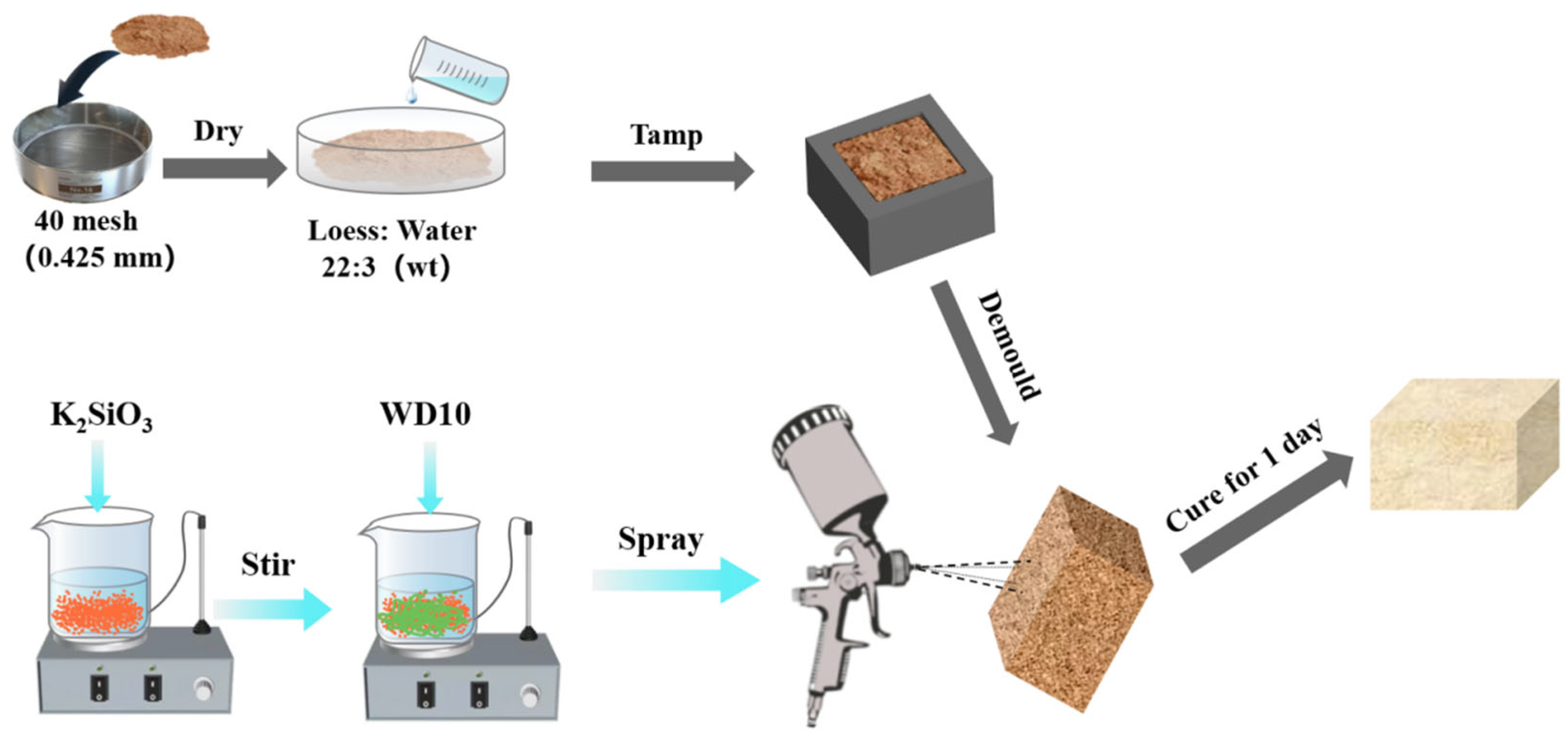
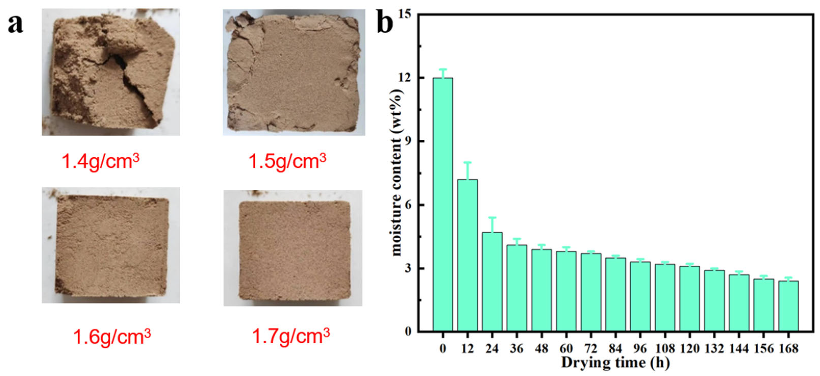
2.1. Preparation of Loess Block Samples

The loess samples used in this study were the surface loess taken from Yulin, Shaanxi Province, China, and were the representative soil samples of the Loess Plateau in China. The preparation process of loess block samples is shown in the upper part of Figure 1. First, the soil blocks of different sizes were crushed, and then the fine particles passing through a 40-mesh (0.425 mm) sieve were collected. They were placed in an oven and dried at 105 °C for 8 h to obtain completely dry loess particle samples. In order to simulate the actual moisture content of loess in the field, we added an appropriate amount of pure water to the loess particle samples to reach a moisture content of about 12 wt%. Then, different masses of humidified loess particle samples were weighed and poured into a rectangular mold with a size of 30 mm × 30 mm × 20 mm. They were evenly hammered on both sides with a rubber hammer until the thickness of the soil block was equal to the height of the mold (20 mm) and then demolded. Finally, it was left to dry for 24 h in a laboratory environment (temperature of about 23 ± 3 °C and relative humidity of about 50%). After weighing, the apparent densities of the prepared loess block samples were calculated to be 1.4, 1.5, 1.6, and 1.7 g cm−3, respectively. As shown in Figure 2a, only the loess block with an apparent density of 1.7 g cm−3 has good integrity and a smooth surface, while other samples with lower density have surface cracks, holes, and even collapse to varying degrees, and, as the apparent density decreases, its surface incompleteness becomes more serious. The loess block sample with an apparent density of 1.4 g cm−3 has almost no integrity. Therefore, in the subsequent experiments, except for special instructions, block samples with an apparent density of 1.7 g cm−3 were used. Figure 2b shows the decrease in moisture content of the loess block sample with an apparent density of 1.7 g cm−3 as the drying time in the laboratory environment increases. It can be seen that, after 24 h, the surface of the sample has been fully dried, and the rate of loss of internal moisture has slowed down significantly, so its moisture content has entered a relatively stable state.

2.2. Preparation of Composite Coatings and Coating Process of Loess Block Samples

The K2SiO3-type water glass (PS for short) with a molar ratio of SiO2 to K2O of 1.8, the solvent of water, and the solid content of about 28 wt% and n-dodecyltrimethoxysilane (WD10, molecular formula is C15H34O3Si) with a viscosity of about 5.7 mPa s at 25 °C were purchased from Beijing Lanyi Chemical Products Co., Ltd., China. The preparation process of the composite coating is shown on the left side of the lower part of Figure 1. First, the PS solution and WD10 were mixed in different proportions as listed in Table 1, and then the composite coating was obtained by stirring at 300 r min−1 for 5 min with a magnetic stirrer. For convenience, the composite coating was named PS-Wx, where x was the mass percentage of WD10 in the composite coating, which was 10, 20, 30, 40, and 50, respectively.
The coating process of the composite coating on the loess block sample is shown on the right side of the lower part of Figure 1. The composite coating was evenly sprayed on all the outer surfaces of the sample with a spray gun at a pressure of about 5 MPa for 5–20 s on each side at a distance of about 10 cm [39], and the spraying amount was about 0.05 g cm−2. The block sample after spraying was placed in the laboratory environment for 3 d, and the subsequent related tests were carried out after the reaction was complete.

2.3. Basic Performance Tests of Loess Block Samples

2.3.1. Determination of Moisture Content of the Loess Samples Collected in the Field

A certain amount of loess samples collected in the field was weighed and put in an oven and dried at 105 °C for 8 h before weighing again. Their moisture content (fw) was calculated with the following formula:
fw = (w0wd)/w0 × 100%
where w0 and wd are the weights of the initial sample and the dried sample, respectively.

2.3.2. Particle Size Test of Loess Particle Samples

The Mastersizer-2000 laser particle size analyzer (LPS) of Malvern, UK, and PANalytical, Almelo, The Netherlands, was used to test the particle size and distribution of loess particle samples.

2.3.3. Determination of Chemical Composition of Loess Particle Samples

The AXIOS max X-ray fluorescence spectrometer (XRF) of PANalytical, Almelo, The Netherlands, was used to test the chemical composition and content of each component of loess particle samples.

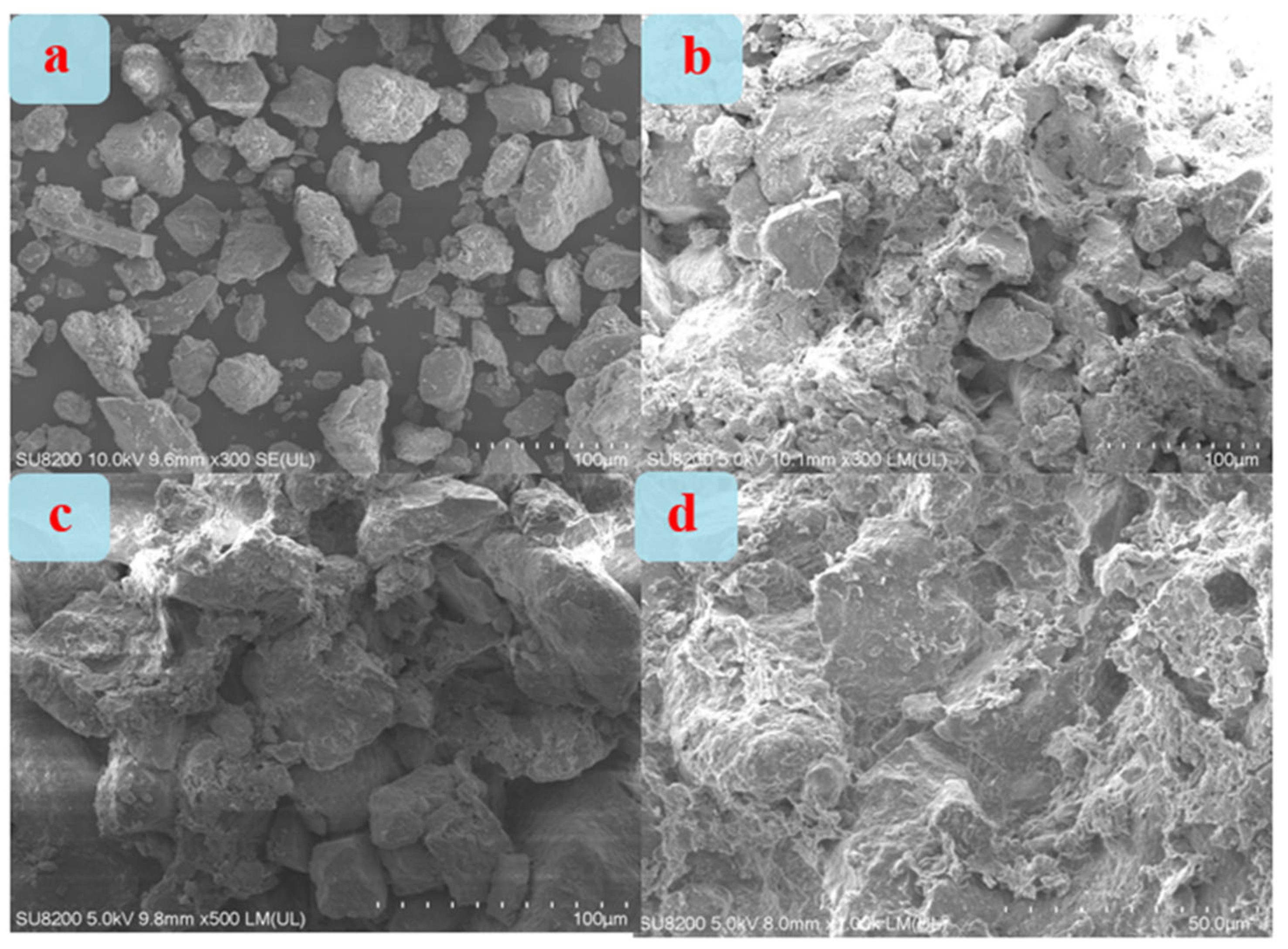
2.3.4. Surface Morphology Observation of Loess Block Samples

A small amount of samples at a depth of about 5 mm were cut from the uncoated and coated loess block samples with different composite coatings using a paper cutter for morphology observation and subsequent other basic performance tests. The sample surface was sprayed with gold before morphology observation to improve the conductivity of the sample. Then, the gold-sprayed loess block sample was bonded to the substrate with conductive tape, and the floating particles on the sample surface were removed. The observation was carried out using an ultra-high-resolution cold field emission scanning electron microscope (Hitachi-SU8220 SEM, Tokyo, Japan) under 10 kV and 0.05 μA. Different magnifications of 300–2000 times were selected for observation.

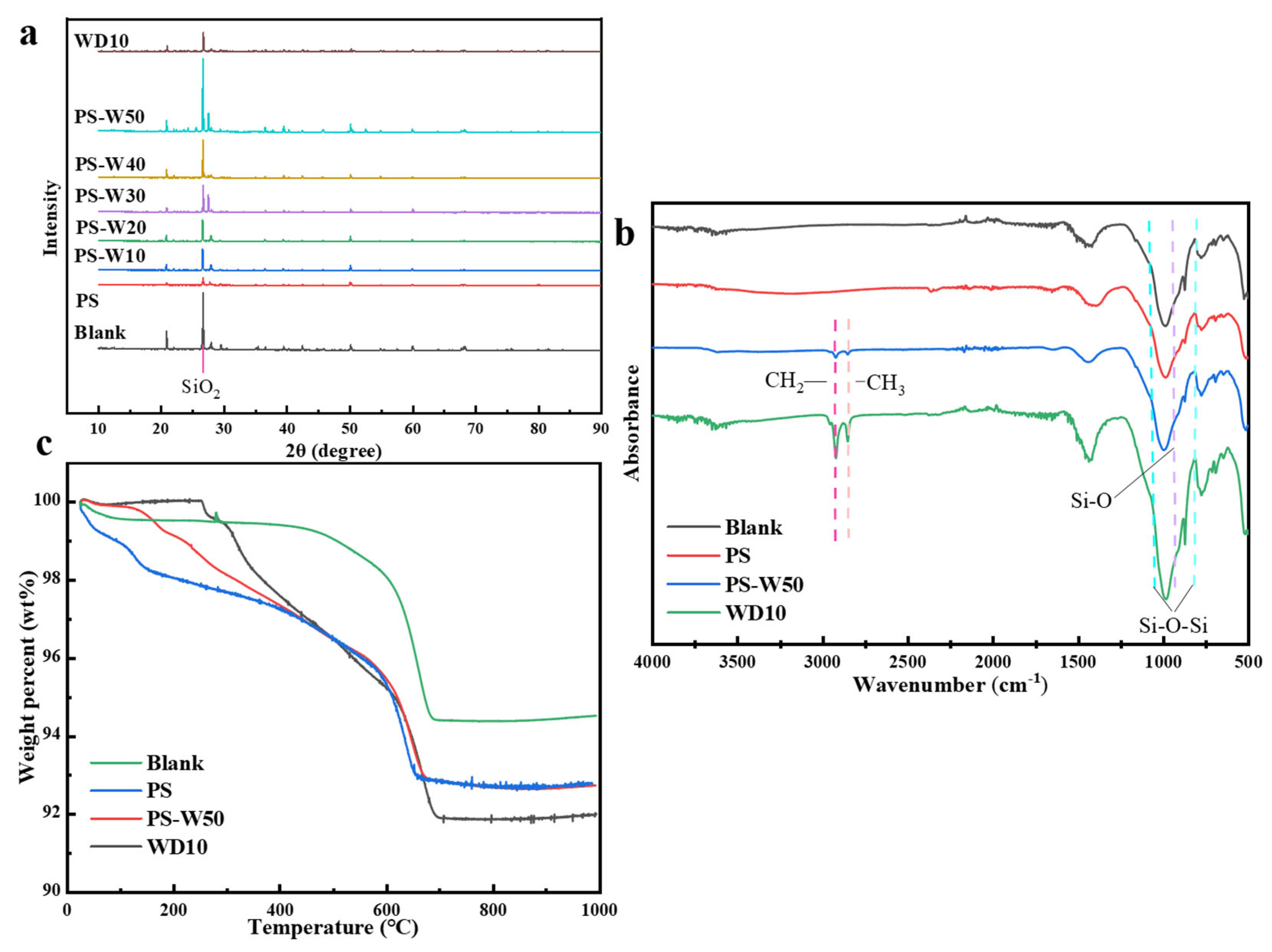
2.3.5. X-Ray Diffractometry (XRD) Test of Loess Block Samples

The samples were tested using the Rigaku Smart Lab 9 kW XRD of Rigaku Co., Ltd. of Tokyo, Japan. Continuous scanning was used. The scanning rate was 10.0° min−1, the scanning range was 10°–90°, and the step length was 0.01°. The Jade 6 software was used to qualitatively analyze the test results.

2.3.6. Fourier Transform Infrared Spectroscopy (FTIR) Test of Loess Block Samples

The iS50 FTIR from Nicolet, Waltham, MA, USA, was used to test the IR spectrum of the samples. Due to the opacity of the samples, ATR mode was used for the measurements. The resolution was 4 cm−1. The direct scanning method was used, and each sample was scanned 32 times, and the average value was taken as the test result.

2.3.7. Thermal Stability Test of Loess Block Samples

The thermal gravimetric analyzer (Q500 TGA from TA, New Castle, DE, USA) was used to test the thermal stability of the samples in a nitrogen/air (4/6, vol/vol) mixed atmosphere. The test was carried out at a rate of 10 °C min−1 from 25 °C to 1000 °C.

2.4. Application Performance Tests of Loess Block Samples

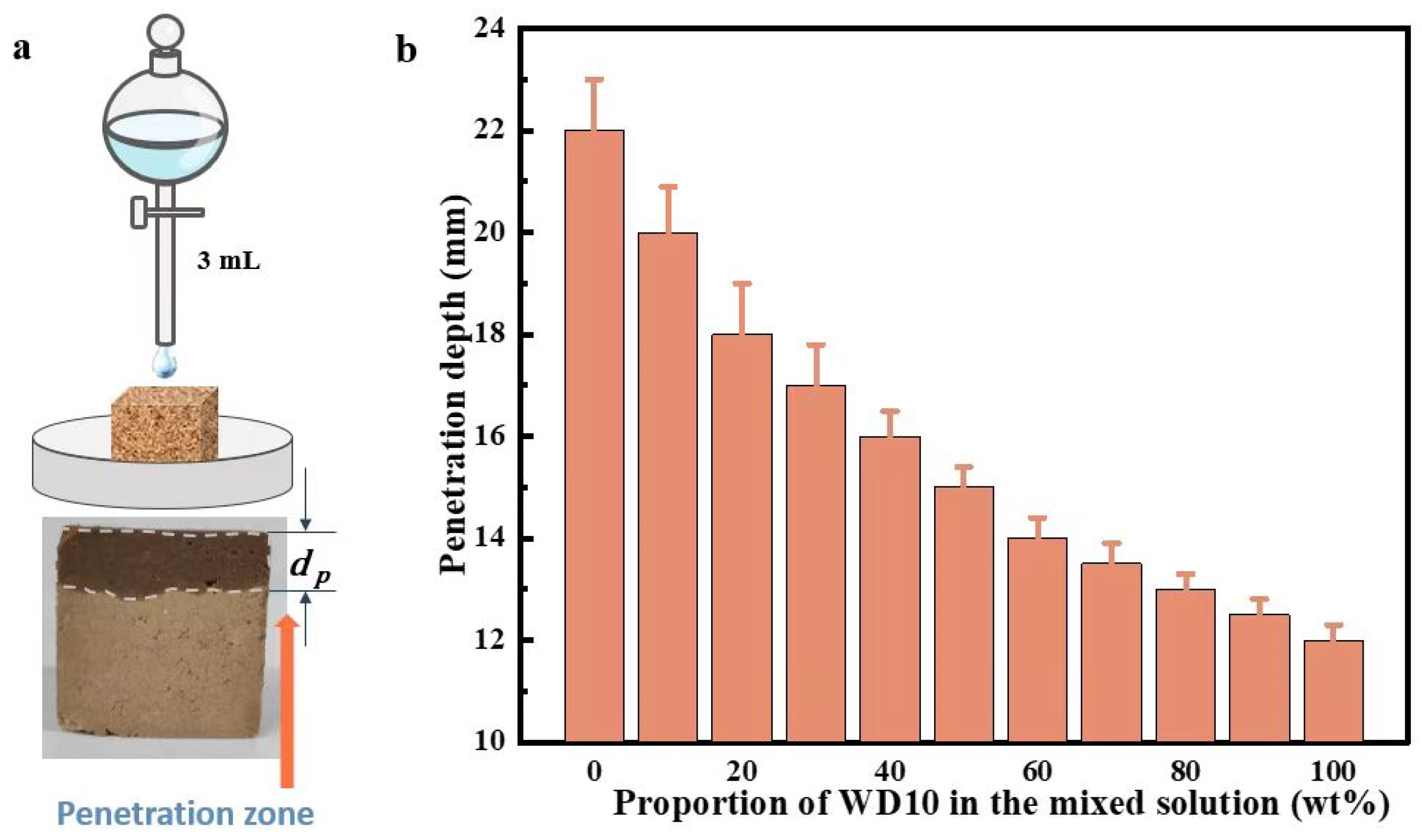
2.4.1. Penetration Test of Coating on Loess Block Samples

The prepared uncoated loess block sample with a size of 30 mm × 30 mm × 20 mm was placed vertically in a Petri dish and the sides were sealed with thin polyvinyl chloride (PVC) film and adhesive. Then 3 mL of composite coating was dropped on the center of the 30 mm × 20 mm upper surface of the sample and allowed to penetrate downward naturally, as shown in the upper part of Figure 3a. After drying for 1 d in the laboratory environment, the sample was cut vertically from the middle along the flat surface, and then an appropriate amount of deionized water was applied to the cross-section. Since the part of the block sample immersed in the composite coating was hydrophobic, the penetration depth could be observed from the boundary between the dry and wet parts, as shown in the lower part of Figure 3a.

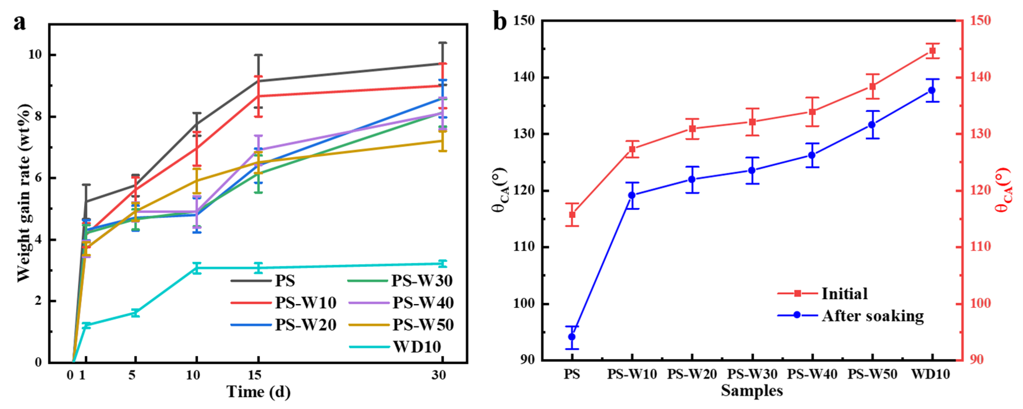
2.4.2. Hydrophobicity Test of Loess Block Samples

The water contact angle test of loess block samples coated with different composite coatings was carried out using the DSA100 contact angle meter of Kruss Company of Germany. A 4 μL water droplet was vertically dropped on the upper surface of the loess block sample, and then the contact angle was immediately observed under a microscope.

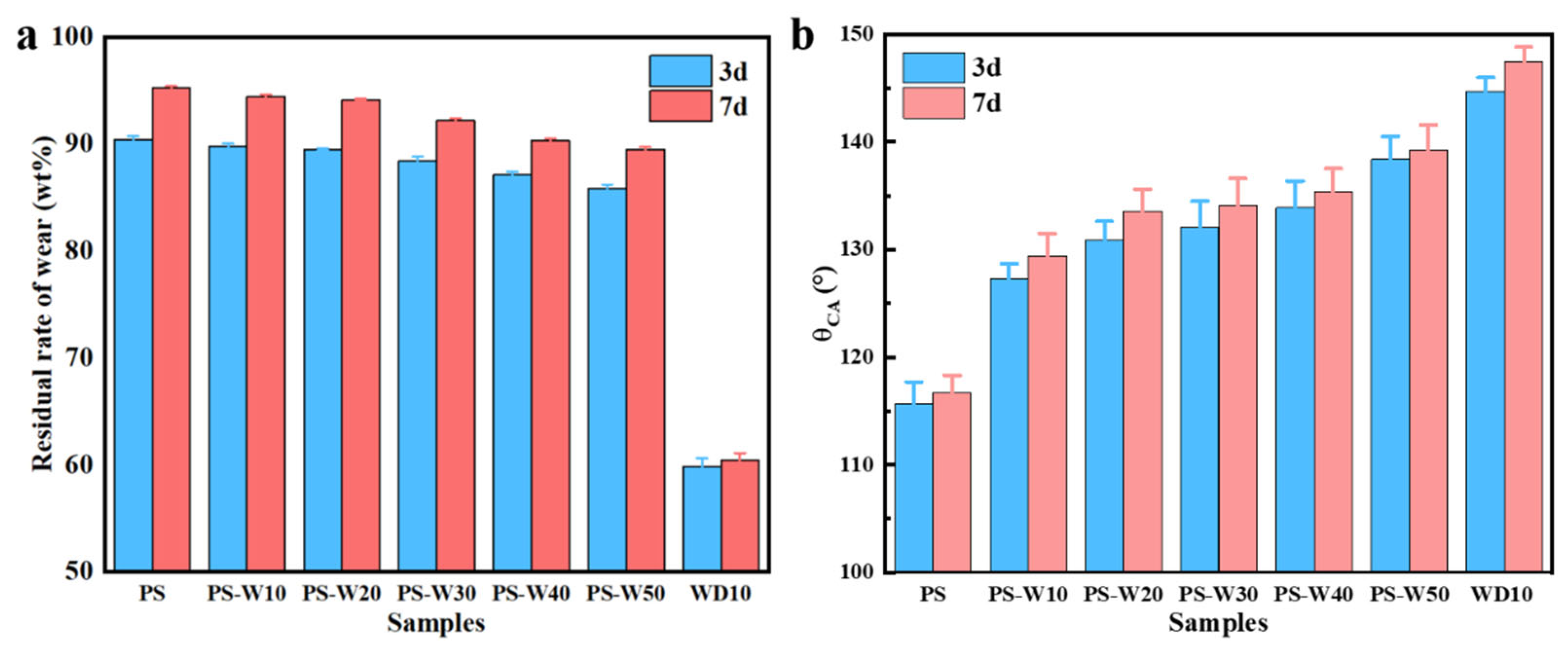
2.4.3. Abrasion Resistance (Structural Strength) Test of Loess Block Samples

As shown in Figure 4, the pre-test sprayed surface of the loess block sample sprayed with different composite coatings was placed face down on the sanded surface of 200-grit sandpaper, and a 200 g metal sheet was placed on the sample as a weight to apply pressure to the contact surface between the sample and the sandpaper. Then the sandpaper strip was slowly and evenly pulled from the bottom of the sample to cause friction between the coating surface of the sample and the sandpaper. Each 50 cm back-and-forth movement was recorded as one cycle, and a total of 50 cycles were tested. The weight of the sample was weighed after 1, 5, 10, 25, and 50 cycles, respectively. Ten samples of each composite coating were tested repeatedly, and the average value was taken to calculate the wear residual rate of the sample. The water contact angle of the friction surface of the block sample was measured after 50 cycles.

2.4.4. Salt Water Resistance Test of Loess Block Samples

Multiple loess block samples coated with different composite coatings were placed in a mixed salt water solution of 3 wt% NaCl and 7 wt% Na2SO4 at the same time. The liquid level of the solution was maintained at about 50 mm above the upper surface of the immersed sample. The samples were separated by more than 10 mm to eliminate interference with each other. The solution was kept in the laboratory environment and renewed every 3 d. The sample was taken out every 5 d to observe whether there were cracks or disintegration on its surface and then put back. After 30 d, all samples were taken out and dried in the laboratory environment for 7 d, and their surface weathering was observed at the same time.

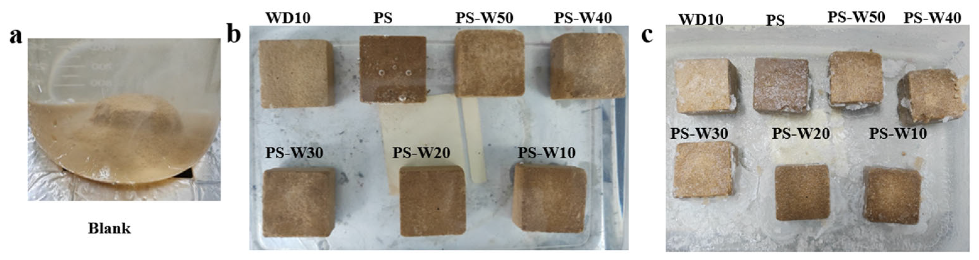
2.4.5. Water Resistance Test of Loess Block Samples

The block samples coated with different composite coatings were put into a beaker containing 1 L of distilled water, and the liquid level of the solution was maintained at about 150 mm above the upper surface of the immersed sample. Each sample was placed in a different beaker to eliminate interference with each other. The evaporated water was replenished every 5 d to keep the liquid level basically unchanged. The samples were taken out at 1, 7, 15, and 30 d, respectively, and the surface was covered with absorbent paper, and then the sample was weighed to calculate the water absorption weight gain rate. At the same time, the corresponding time of particle shedding, wet collapse, and block disintegration on the sample surface was recorded. Then it was put back. After 30 d, all samples were taken out and their water contact angles were measured. They were kept for subsequent freeze–thaw resistance tests.

2.4.6. Freeze–Thaw Resistance Test of Loess Block Samples

After wiping the surface of the block sample after the 30 d water resistance test with absorbent paper, it was placed at 20 °C for 12 h and then at −20 °C for 12 h, which was recorded as one cycle. After a total of 30 cycles, it was thawed in the laboratory environment for 6 h, and then its surface integrity, surface particle shedding, and block disintegration were observed. If particle shedding or even block disintegration occurred before 30 cycles, the corresponding cycle number was recorded.

3. Results and Discussion

3.1. Basic Properties of Loess Particles

As shown in Table 2, XRF test shows that the main components of loess particle samples are oxides such as SiO2, Al2O3, Fe2O3, and CaO, and there is also water content of about 0.6 wt%. As shown in Figure 5, the laser particle size analysis shows that the particle size distribution range of loess particle samples is mainly 40–60 μm. The calculated specific surface area is about 0.298 m2 g−1, the area average particle size is about 20.1 μm, and the volume average particle size is about 50.6 μm.

3.2. Improvement of Structural Strength and Hydrophobicity of Loess Block Samples by Surface Coating

Figure 3b shows the different penetration depths of different composite coatings in loess block samples. It can be seen that the penetration depth of PS solution is the largest, reaching about 22 mm, while the penetration depth of WD10 is the smallest, only about 12 mm; the penetration depth of other mixed solutions is between the two and gradually decreases with the increase in WD10 content. The reason might be that the hydrophobicity and viscosity of WD10 are much higher than those of PS solution, and loess itself has a high hydrophilicity. Therefore, with the increase in WD10 content, the hydrophobicity and viscosity of the composite coating increase, making it more difficult to penetrate into the pores of the loess block sample.
The main components of PS solution are K2SiO3 and H2SiO3 gel. Its most common preparation method is to first dissolve potassium hydroxide (KOH) in water, then add silicon dioxide (SiO2), and stir evenly to obtain it. The reaction formula is:
2KOH + nSiO2·+ (m − 1)H2O → K2O·nSiO2·mH2O
When the PS aqueous solution penetrates into the pores of the loess block, the K+ ions in K2SiO3 can exchange with Ca2+, Mg2+, etc., in the loess and generate salt particles such as CaSiO3 and MgSiO3 after dehydration. At the same time, due to the effect of H2SiO3 gel, the pores between loess particles are filled together, and the connection strength between different particles is greatly improved, thereby improving the structural strength of the soil.
After WD10 is sprayed, the alkoxy group (-OC2H5) in it will react with the water molecules in the PS solution and hydrolyze to form silanol. The reaction formula is:
R-Si(OC2H5)3 + 3H2O → R-Si(OH)3 + 3HOC2H5
As a highly reactive intermediate, silanol groups will self-polymerize with each other. The reaction formula is:
2R-Si(OH)3 → R-Si(OH)2-O-Si(OH)2-R + H2O
Silanol may also react with the hydroxyl (-OH) on the surface of loess particles to form a -Si-O-Si- crosslinked network [40,41], which plays a role in connecting different loess particles, thereby improving its structural strength. The reaction formula is:
R-Si(OH)3 + -Si(Loess)≡(OH)3 → R-SiO3≡Si(Loess)- + 3H2O
As shown in Figure 6, for the loess block samples sprayed with different composite coatings, as the drying and reaction time in the laboratory environment increased from 3 d to 7 d, the weight wear residual rate and surface water contact angle of the coating increased, which could be attributed to the continuous formation of silicate, H2SiO3 gel, and -Si-O-Si- crosslinked network.
Figure 7 shows SEM photos of different loess block samples. As shown in Figure 7a, the uncoated loess particles are irregular in shape, relatively smooth in surface, weakly connected to each other, and have a large number of pores in the block, which cannot hinder the rapid penetration of water in it. As shown in Figure 7b, there are a large number of small particles attached to the surface of large particles in the sample coated with PS coating. These small particles are mainly salt particles such as K2SiO3, CaSiO3, MgSiO3, and H2SiO3 gel precipitated after dehydration of PS solution. They all play the role of filling the pores between loess particles and connecting different loess particles, thus greatly reducing the porosity of the loess block and can hinder the penetration of water in it to a certain extent. As shown in Figure 7c, there are flocculent substances wrapped on the surface of loess particles in the sample coated with WD10 coating. These are mainly crosslinked products produced after WD10 reaction. They can not only fill the pores between loess particles and connect different loess particles but also have excellent hydrophobicity, so they can well hinder the penetration of water in the loess block. As shown in Figure 7d, the particle morphology of the sample coated with PS-W50 coating has the characteristics of both of the previous two, that is, there are a certain amount of small particles attached to the surface of large particles and a certain amount of flocculent substances wrapped on the loess surface. Therefore, its block’s ability to hinder water penetration is also between the previous two but closer to the sample coated with WD10 coating.
Figure 8a is the XRD spectrum of different loess block samples. The principle of XRD for measuring the proportion of each element in the samples is as follows. After the sample is pressed with a backing sheet, the atoms in the sample are excited by appropriate high-energy radiation, and characteristic X-rays with specific properties are emitted by these atoms. The intensity of these characteristic X-rays is proportional to the concentration of the corresponding element in the sample. Thus, by measuring the intensity of the characteristic X-rays, the content of each element in the sample can be quantitatively determined. It can be seen that the diffraction peaks of the uncoated loess sample in the range of 20–40° (non-clay minerals) are larger than those in the range of 10–20° (clay minerals), which indicates that non-clay minerals (such as quartz, albite, etc.) dominate the composition of loess [42,43]. The diffraction peak at 26° belongs to SiO2, whose intensity decreases with the increase in PS content in the composite coating, but its position does not change.
Figure 8b shows the FTIR spectra of different loess block samples. It can be seen that the main absorption peaks of the uncoated loess sample are the Si-O-Si asymmetric vibration peaks at 786 cm−1 and 1032 cm−1, the Si-O stretching vibration peak at 876 cm−1, and the -OH stretching vibration peak near 3400 cm−1. The Si-O-Si peak intensity of the sample coated by PS solution is reduced, which may be due to the breakage of Si-O bonds in the system. The Si-O-Si peaks at 786 cm−1 and 1032 cm−1 of the sample coated by WD10 are slightly enhanced and there are stretching vibration peaks and bending vibration peaks corresponding to -CH3 and -CH2 at 2925 cm−1 and 2850 cm−1, respectively. For the sample coated by the composite coating, the intensity of its Si-O-Si peak does not change significantly, because there are both the generation of Si-O-Si groups caused by the crosslinking reaction of WD10 and the cleavage of Si-O groups in the system.
Figure 8c is the TGA curves of different loess block samples. It can be seen that the thermal decomposition process of the uncoated loess sample can be divided into two stages; the weight loss before heating to 400 °C is only about 0.5 wt%, which is mainly due to the loss of adsorbed water and bound water in the sample; the weight loss to 650 °C is about 5 wt%, which is due to the thermal decomposition of organic matter in the sample that decomposes into gas and solid residues. The weight loss of the sample coated by PS solution to 400 °C is about 2.5 wt%, which is mainly due to the thermal decomposition of H2SiO3 gel in PS, and its weight loss trend to 650 °C is basically the same as that of the uncoated loess. The weight loss of the sample coated by WD10 to 400 °C is also about 2.5 wt%, which is mainly due to the thermal decomposition of the crosslinked network formed by WD10, and its weight loss trend to 650 °C is also basically the same as that of the uncoated loess. The weight loss curve of the loess sample coated by PS-W50 is between the sample coated by PS solution and the sample coated by WD10.

3.3. Improvement of Practical Performance of Loess Block Samples by Surface Coating

Figure 9 shows the changes in surface water contact angle and residual weight percentage of loess block samples coated with different composite coatings with the number of frictions. It can be seen that the surface water contact angle and residual weight percentage of all samples gradually decrease with the increase in the number of frictions. Among them, the water contact angle of the sample coated with WD10 decreases the most, and its weight is only about 60 wt% after 50 frictions. This is because the penetration depth of WD10 in the block is lower than that of other coatings, resulting in a lower thickness of the consolidated layer on the surface of the sample than other samples. After 5 cycles of grinding, the contact angle of the sample coated with PS solution decreases the least and remains near 113°; after 25 cycles, although the weight loss is close to 5 wt%, the water contact angle is still above 110°; after 50 cycles, the weight loss rate is close to 10 wt%, but the water contact angle is still above 110°. This should be attributed to the penetration depth of PS solution in the loess block, which is greater than that of all other samples. The loess block sample coated with the composite coating is between the samples coated with the single coating of WD10 and the PS solution and has a greater decrease in water contact angle and weight loss with the increase in WD10 content. Interestingly, the water contact angle of the samples coated with several composite coatings decreases closer to that of the samples coated with WD10, while their weight loss rate is closer to that of the samples coated with PS solution. For the loess block samples coated with the composite coatings, after 50 cycles of friction, the weight loss rate is still less than 15 wt%, and the water contact angle is still above 120°. Therefore, the hydrophobicity of the composite coating depends more on WD10, while the penetration depth depends more on the PS solution.
Figure 10 shows the state of the uncoated loess block sample after immersion in salt water for 30 s, as well as the initial state and the state after immersion for 7 d of the loess block sample coated with different composite coatings. It was found in the experiment that the uncoated loess block sample immediately began to absorb water and generate bubbles after contacting the salt water, then quickly disintegrated from the edge, and severely disintegrated after 30 s (as shown in Figure 10a); after 10 min, it completely disintegrated and formed fine particles. This shows that the uncoated loess block sample has extremely poor salt water resistance. As for the loess block samples coated with different composite coatings, a small amount of bubbles overflowed from the samples coated with PS solution after contacting with salt water; after immersion for 7 d, the number of bubbles attached to its surface was still slightly higher than that of the samples coated with other coatings, and particles began to fall off from the edge of the sample (as shown in Figure 10b); after immersion for 15 d, there were still a small number of bubbles on its surface, but the particle shedding did not increase significantly. These results show that the loess block samples consolidated by PS have a certain salt water resistance. However, only trace bubbles appeared in the loess block samples coated with WD10, PS-W10, PS-W20, PS-W30, and PS-W40 coatings after contacting with salt water. Among them, after immersion for 7 d, a very small amount of bubbles attached to the side of the PS-W10 sample, but its surface remained intact; after immersion for 15 d, the bubbles on its surface disappeared, and no particles fell off. However, no bubbles appeared on the surface of the loess block samples coated with PS-W50 and WD10 coatings after contacting with salt water; after immersion for 7 d, there were still no bubbles attached to the surface and it remained intact; after immersion for 15 d, there were still no bubbles on the surface, and no particles fell off. This shows that the addition of WD10 greatly improved the salt water resistance of the loess block samples. The possible mechanism is that, after WD10 enters the pores of the loess block, it covers the surface of the particles, which not only reduces the volume of the pores but also hinders the entry of salt water into the pores due to its hydrophobicity. In addition, the crosslinking reaction of WD10 also makes the originally loose loess particles have a stronger connection. After immersion in salt water for 15 d, all loess block samples were taken out and placed in a laboratory environment to dry for 60 d. The samples coated with WD10 and PS-W30, PS-W40, and PS-W50 composite coatings did not show surface weathering, and the surface showed a certain white color (as shown in Figure 10c). This is because the hydrophobicity imparted by WD10 hinders the infiltration of salt water, so that salt particles were deposited on the surface of the sample after the salt water dried, while no white salt particles were seen on the surface of the sample coated with less WD10 content and PS solution coating and, as the WD10 content decreased, the surface weathering phenomenon became more serious.
The pure water immersion test of the block samples without coating and coated with different composite coatings showed that there was not much difference from the salt water resistance test for the uncoated sample, while the weight gain rate of the samples coated with different composite coatings gradually decreased with the increase in WD10 content in the composite coating, as shown in Figure 11a. Among them, the samples coated with PS solution had more bubbles at the beginning of immersion because the PS solution was not enough to fill the pores on the surface of the sample, so a small amount of water molecules could still penetrate from the pores into the sample, and the air inside the sample escaped. Correspondingly, its weight gain rate was higher at the beginning of immersion; after immersion for 30 d, fine particles fell off at its edge, but the block did not disintegrate; after immersion for 60 d, larger particles fell off on the surface, accompanied by slight disintegration. This shows that, although the water resistance of the loess block samples consolidated by PS solution has been greatly improved compared with the samples without coating, it still does not meet the requirements of long-term waterproofing. However, the surfaces of the blocks coated with WD10 or composite coatings remained intact after immersion for 60 d, and no particles fell off. This fully demonstrates that the addition of WD10 further improves the water resistance of loess. However, after immersion for 60 d, the blocks coated with WD10 or composite coatings were taken out and dried in the laboratory environment for 3 d, and the surface water contact angle test showed that they had basically lost their hydrophobic properties. After grinding off a layer of about 1 mm on the surface of these samples with 200-grit sandpaper, the surface water contact angle was measured. The block samples coated with WD10 or composite coatings still showed good hydrophobicity, although slightly lower than the hydrophobicity of the samples before immersion, while the samples coated with PS solution almost lost their hydrophobicity, as shown in Figure 11b. This shows that the addition of WD10 effectively hinders the water penetration.
Figure 12 shows the surface morphology of loess block samples coated with different composite coatings after 30 freeze–thaw cycles. It can be seen that the surface of the sample coated only by PS solution has missing corners. In fact, particles began to fall off after the 10th cycle and then gradually became serious in the subsequent cycles, but there was no large-scale shedding or even disintegration until the 30th cycle. The samples coated by WD10 and composite coatings remained basically intact after 30 cycles. This fully demonstrates that the good hydrophobicity of WD10 almost completely blocks the penetration of water, while the PS single coating is more easily penetrated by water. The good freeze–thaw resistance of the samples coated by WD10 and composite coatings gives them good weather resistance to the change in winter and spring seasons. This is very important for its practical application.
To sum up, as shown in Figure 13, PS has much better permeability but much poorer hydrophobicity than WD10. The PS-W50, which combines the advantages of both PS and WD10, can produce the good synergistic effect of both good permeability and excellent hydrophobicity, which is beneficial to the significant improvement in structural strength and water resistance of loess blocks for the silt dam.

4. Conclusions

In response to the drawbacks of loose structure, low mechanical strength, and easy collapse of loess used in water conservancy projects such as silt dams, this study optimized the improvement in the structural strength and water resistance of loess blocks by adding WD10 with excellent hydrophobicity to PS solution to prepare composite coatings. Through in-depth and systematic research on the morphology, chemical composition, consolidation mechanism, friction resistance, hydrophobicity, resistance to pure water and salt water immersion, and resistance to freeze–thaw cycles of the material system, it was found that the composite coating had better consolidation performance for loess blocks than the single coating of PS solution and WD10. This can be attributed to the good synergistic effect of the good permeability of the PS solution and the excellent hydrophobicity of WD10. The loess blocks coated with such composite coatings are expected to replace traditional functional materials for water conservancy projects, such as cement and lime, in silt dam water conservancy projects, to achieve the maximum benefits in terms of environmental protection, sustainability, and economy.

Author Contributions

Conceptualization, J.Z. and H.Z.; methodology, J.Z. and H.Z.; investigation, Y.X., B.J., K.Z. and G.Z.; resources, H.Z.; data curation, Y.X., B.J. and H.J.; writing—original draft preparation, Y.X. and B.J.; writing—review and editing, J.Z., H.Z., X.Z. and L.X.; supervision, J.Z. and H.Z.; project administration, H.Z.; funding acquisition, H.Z. All authors have read and agreed to the published version of the manuscript.

Funding

The Shaanxi Provincial Water Conservancy Science and Technology Project “Application Research of Nano-Coatings in the Construction of New Silt Dams” (Grant No. 2023slkj-11) and the National Key R&D Program of China (Grant No. 2016YFC0207104).

Institutional Review Board Statement

Not applicable.

Informed Consent Statement

Not applicable.

Data Availability Statement

Data are contained within the article.

Conflicts of Interest

Authors Kai Zhang and Gang Zhang are employed by the company Shaanxi Province Institute of Water Resources and Electric Power Investigation and Design (Group) Co., Ltd. The remaining authors declare that the research was conducted in the absence of any commercial or financial relationships that could be construed as a potential conflict of interest.

References

  1. Costantini, E.A.; Carnicelli, S.; Sauer, D.; Priori, S.; Andreetta, A.; Kadereit, A.; Lorenzetti, R. Loess in Italy: Genesis, characteristics and occurrence. Catena 2018, 168, 14–33. [Google Scholar] [CrossRef]
  2. Furlan, A.P.; Razakamanantsoa, A.; Ranaivomanana, H.; Amiri, O.; Levacher, D.; Deneele, D. Effect of fly ash on microstructural and resistance characteristics of dredged sediment stabilized with lime and cement. Constr. Build. Mater. 2021, 272, 121637. [Google Scholar] [CrossRef]
  3. Gu, K.; Chen, B. Loess stabilization using cement, waste phosphogypsum, fly ash and quicklime for self-compacting rammed earth construction. Constr. Build. Mater. 2020, 231, 117195. [Google Scholar] [CrossRef]
  4. Jiang, P.; Chen, Y.; Li, N.; Zhou, L.; Pu, S.; Wang, W. Strength properties and microscopic mechanism of lime and fly ash modified expandable poly styrene lightweight soil reinforced by polypropylene fiber. Case Stud. Constr. Mater. 2022, 17, e01250. [Google Scholar] [CrossRef]
  5. Romero-Diaz, A.; Marin-Sanleandro, P.; Ortiz-Silla, R. Loss of soil fertility estimated from sediment trapped in check dams. South-eastern Spain. Catena 2012, 99, 42–53. [Google Scholar] [CrossRef]
  6. Galicia, S.; Navarro-Hevia, J.; Martínez-Rodríguez, A.; Mongil-Manso, J.; Santibáñez, J. ‘Green’, rammed earth check dams: A proposal to restore gullies under low rainfall erosivity and runoff conditions. Sci. Total Environ. 2019, 676, 584–594. [Google Scholar] [CrossRef]
  7. Xu, P.; Qian, H.; Zhang, Q.; Zheng, L. Exploring the saturated permeability of remolded loess under inorganic salt solution seepage. Eng. Geol. 2021, 294, 106354. [Google Scholar] [CrossRef]
  8. Xu, P.; Zhang, Q.; Qian, H.; Li, M.; Yang, F. An investigation into the relationship between saturated permeability and microstructure of remolded loess: A case study from Chinese Loess Plateau. Geoderma 2021, 382, 114774. [Google Scholar] [CrossRef]
  9. Zhang, Y.; Qian, H.; Hou, K.; Qu, W. Investigating and predicting the temperature effects of permeability for loess. Eng. Geol. 2021, 285, 106050. [Google Scholar] [CrossRef]
  10. Xu, P.; Qian, H.; Zhang, Q.; Shang, J.; Guo, Y.; Li, M. Response mechanism of permeability change of remolded loess to seepage parameters. J. Hydrol. 2022, 612, 128224. [Google Scholar] [CrossRef]
  11. Yang, H.; Xie, W.; Liu, Q.; Zhu, R.; Liu, Y. Three-stage collapsibility evolution of Malan loess in the Loess Plateau. Catena 2022, 217, 106482. [Google Scholar] [CrossRef]
  12. Yao, Y.; Zhang, Y.; Gao, X.; Huang, H.; Liu, D.; Hui, X. Study on permeability and collapsibility characteristics of sandy loess in northern Loess Plateau, China. J. Hydrol. 2021, 603, 126883. [Google Scholar] [CrossRef]
  13. Zheng, Z.; Li, X.; Wang, L.; Li, L.; Shi, J.; Bi, M. A new approach to evaluation of loess collapsibility based on quantitative analyses of colloid-clay coating with statistical methods. Eng. Geol. 2021, 288, 106167. [Google Scholar] [CrossRef]
  14. Sun, X.; Miao, L.; Chen, R.; Wang, H.; Xia, J. Surface rainfall erosion resistance and freeze-thaw durability of bio-cemented and polymer-modified loess slopes. J. Environ. Manag. 2022, 301, 113883. [Google Scholar] [CrossRef]
  15. Cheng, Y.; Tang, C.; Pan, X.; Liu, B.; Xie, Y.; Cheng, Q.; Shi, B. Application of microbial induced carbonate precipitation for loess surface erosion control. Eng. Geol. 2021, 294, 106387. [Google Scholar] [CrossRef]
  16. Zhang, H.; Liu, G.; Zhao, C.; Zhang, L.; Zhang, Q.; Fu, H.; Cao, S. Loess erosion change modeling during heavy rainfall, International. J. Sediment Res. 2023, 38, 24–32. [Google Scholar] [CrossRef]
  17. Wu, Z.; Zhang, D.; Wang, S.; Liang, C.; Zhao, D. Dynamic-response characteristics and deformation evolution of loess slopes under seismic loads. Eng. Geol. 2020, 267, 105507. [Google Scholar] [CrossRef]
  18. Li, Y. A review of shear and tensile strengths of the Malan Loess in China. Eng. Geol. 2018, 236, 4–10. [Google Scholar] [CrossRef]
  19. Wang, J.; Gu, T.; Zhang, M.; Xu, Y.; Kong, J. Experimental study of loess disintegration characteristics. Earth Surf. Process. Landf. 2019, 44, 1317–1329. [Google Scholar] [CrossRef]
  20. Li, X.; Wang, L.; Yan, Y.; Hong, B.; Li, L. Experimental study on the disintegration of loess in the Loess Plateau of China. Bull. Eng. Geol. Environ. 2019, 78, 4907–4918. [Google Scholar] [CrossRef]
  21. Lin, H.; Wang, J.; Xu, Y. Synergistic effects and mechanism of locomotive vibration and chemical dissolution on loess disintegration. J. Soils Sediments 2022, 22, 3106–3118. [Google Scholar] [CrossRef]
  22. Li, H.; Yang, M.; Guo, X. Study of the disintegration of loess modified with fly ash and Roadyes. Sci. Rep. 2023, 13, 7253. [Google Scholar] [CrossRef]
  23. Axel, M.; Li, X.; Wen, F.; An, M. Microstructure and strength parameters of cement-stabilized loess. Geotechnics 2023, 3, 161–178. [Google Scholar] [CrossRef]
  24. Zhao, W.; Guo, C.; Wang, C.; Wang, Y.; Wang, L. Study on mechanical properties of permeable polymer treated loess. Materials 2022, 15, 6647. [Google Scholar] [CrossRef]
  25. Dassekpo, J.-B.M.; Zha, X.; Zhan, J. Synthesis reaction and compressive strength behavior of loess-fly ash based geopolymers for the development of sustainable green materials. Constr. Build. Mater. 2017, 141, 491–500. [Google Scholar] [CrossRef]
  26. Zhang, X.; Zhong, Y.; Pei, X.; Duan, Y. A cross-linked polymer soil stabilizer for hillslope conservation on the Loess Plateau. Front. Earth Sci. 2021, 9, 771316. [Google Scholar] [CrossRef]
  27. Chen, G.; Xu, Y.; Zhang, Y.; Yan, M. Study on the differential disintegration mechanism of water glass cured sandy soil: Analysis from the perspective of the coexistence state of gel and particles. Acta Geotech. 2024, 19, 2191–2212. [Google Scholar] [CrossRef]
  28. Xu, Y.; Zhang, Y.; Huang, J.; Chen, G. Mechanical properties, microstructure and consolidation of sand modified with sodium silicate. Eng. Geol. 2022, 310, 106875. [Google Scholar] [CrossRef]
  29. Yu, X.; Lu, H.; Peng, J.; Ren, J.; Wang, Y.; Chen, J. Modified lignin-based cement solidifying material for improving engineering residual soil. Materials 2023, 16, 7100. [Google Scholar] [CrossRef]
  30. Kuang, L.; Li, G.; Xiang, J.; Ma, W.; Cui, X. Effect of seawater on the properties and microstructure of metakaolin/slag-based geopolymers. Constr. Build. Mater. 2023, 397, 132418. [Google Scholar] [CrossRef]
  31. Li, J.; Du, M.; Cheng, Y.; Wang, S.; Chen, J.; Hu, S.; Zhang, H.; Zhang, H. Condensation and hydrophobicity of the surface hydroxyl groups between organosilane modified water glass and microsilica. Ceram. Int. 2023, 49, 21278–21286. [Google Scholar] [CrossRef]
  32. Hu, S.; Zhang, W. Effect of spent waterglass foundry sand on the performance of MgO-activated slag materials. Front. Mater. 2023, 10, 1207246. [Google Scholar] [CrossRef]
  33. Fei, M.; Fu, W.; Zheng, X.; Chen, Y.; Liu, W.; Qiu, R. Enhancing cement composite interface with waterglass modification on bamboo fiber: A viable and effective approach. Constr. Build. Mater. 2024, 411, 134338. [Google Scholar] [CrossRef]
  34. Jiang, F.; Hao, Y.; Wu, H.; Liu, Y.; Wang, Z.; Tan, B.; Zhang, C.; Lan, M. Study on damage degradation and radon emission from uranium tailing polymer-solidified soil under freeze-thaw cycles. J. Radioanal. Nucl. Chem. 2022, 331, 1573–1583. [Google Scholar] [CrossRef]
  35. Duan, X.; Xiao, D.; Zou, Y.; Dong, Q.; Ye, W.; Tang, L. Permeability characteristics and mechanism of silicone-hydrophobic-powder-modified compacted loess. Sustainability 2023, 15, 6606. [Google Scholar] [CrossRef]
  36. Liu, Z.; Wang, J. TEOS modified with PMHS as consolidating coating to improve the strength and hydrophobicity of earthen structures. Constr. Build. Mater. 2022, 322, 126165. [Google Scholar] [CrossRef]
  37. Li, X.; Ma, Q.; Ji, Y.; Cheng, K.; Sun, Z. Study on the improvement of waterproof performance of historical silt sites with silicone waterproofing agent. Coatings 2022, 12, 1162. [Google Scholar] [CrossRef]
  38. Zhu, M.; Zhang, H.; Jiang, Z.; Zhang, L.; Xue, X.; Zhang, Z. Water-proof organosilicon coating for Aga soil in Tibet. Synth. Mater. Aging Appl. 2021, 50, 1–6+13. (In Chinese) [Google Scholar]
  39. Nadaraia, K.V.; Suchkov, S.N.; Imshinetskiy, I.M.; Mashtalyar, D.V.; Kosianov, D.Y.; Belov, E.A.; Sinebryukhov, S.L.; Gnedenkov, S.V. New superhydrophobic composite coatings on Mg-Mn-Ce magnesium alloy. J. Magnes. Alloys 2023, 11, 1721–1739. [Google Scholar] [CrossRef]
  40. Paquet, O.; Salon, M.-C.B.; Zeno, E.; Belgacem, M.N. Hydrolysis-condensation kinetics of 3-(2-amino-ethylamino)propyl-trimethoxysilane. Mater. Sci. Eng. C 2012, 32, 487–493. [Google Scholar] [CrossRef]
  41. Salon, M.-C.B.; Belgacem, M.N. Competition between hydrolysis and condensation reactions of trialkoxysilanes, as a function of the amount of water and the nature of the organic group. Colloids Surf. A Physicochem. Eng. Asp. 2010, 366, 147–154. [Google Scholar] [CrossRef]
  42. Mu, Q.Y.; Zhou, C.; Ng, C.W.W. Compression and wetting induced volumetric behavior of loess: Macro- and micro-investigations. Transp. Geotech. 2020, 23, 100345. [Google Scholar] [CrossRef]
  43. Liu, Y.; Yang, Y.; Dong, Y.; Lv, Y.; Wang, D.; Qi, L. Mechanical properties and microstructure characteristics of the loess modified by the consolid system. Adv. Mater. Sci. Eng. 2022, 2022, 1628985. [Google Scholar] [CrossRef]
Figure 1. Schematic diagram of the preparation of loess block samples (upper part) and composite coatings (lower part left) and the coating process of composite coatings on loess block samples (lower part right).
Coatings 15 00782 g001
Figure 2. Morphology of the loess block samples with different apparent densities (a) and change in moisture content of the loess block samples with an apparent density of 1.7 g cm−3 with drying time (b). In part a, all the samples are in the same rectangular shape with the same size of 30 mm × 30 mm × 20 mm.
Coatings 15 00782 g002
Figure 3. Measurement of coating permeability of loess by direct titration: experimental schematic diagram and cross-sectional diagram after the coating penetrates the sample (a) and penetration depth of 3 mL of different composite coatings in the loess block sample (b).
Coatings 15 00782 g003
Figure 4. Schematic diagram of wear resistance test (a), actual wear resistance test device (b), and the shape of water droplets on the friction surface of the loess block sample sprayed with PS-W50 coating after 50 cycles of friction (c).
Coatings 15 00782 g004
Figure 5. Particle size distribution of loess particle samples.
Coatings 15 00782 g005
Figure 6. Effect of reaction time on the weight wear residual rate (a) and water contact angle (b) of loess block samples coated with different composite coatings.
Coatings 15 00782 g006
Figure 7. SEM photos of different loess block samples: uncoated (a) and coated with PS (b), WD10 (c), and PS-W50 (d) coatings.
Coatings 15 00782 g007
Figure 8. XRD spectrum (a), FTIR spectrum (b), and TGA curves (c) of loess block samples coated with different composite coatings.
Coatings 15 00782 g008
Figure 9. Changes in surface water contact angle (a) and residual weight percentage (b) of loess block samples coated with different composite coatings with the number of frictions.
Coatings 15 00782 g009
Figure 10. The state of the uncoated loess block sample after immersion in salt water for 30 s (a), and the loess block samples coated with different composite coatings after immersion for 7 d (b) and after immersion for 15 d and then drying for 60 d (c). In parts b and c, all the samples are in the same rectangular shape with the same size of 30 mm × 30 mm × 20 mm.
Coatings 15 00782 g010
Figure 11. Changes in weight gain rate of loess block samples coated with different composite coatings during pure water immersion (a) and comparison of water contact angles of block samples coated with different composite coatings before immersion and after immersion and scraping off the 1 mm thick surface layer (b).
Coatings 15 00782 g011
Figure 12. Surface morphology of loess block samples coated with different composite coatings after 30 freeze–thaw cycles. All the samples are in the same rectangular shape with the same size of 30 mm × 30 mm × 20 mm.
Coatings 15 00782 g012
Figure 13. Schematic diagram of the significantly different permeabilities of PS (a), WD10 (b), and PS-W50 (c), respectively, in the loess block samples, where the yellow polygons represent the loess particles, the white space represents the pores between loess particles, and the blue, red, and purple blocks represent PS, WD10, and PS-W50, respectively. The arrows indicate the spray direction of the coatings.
Coatings 15 00782 g013
Table 1. Composition of composite coatings.
Composite CoatingPS-W10PS-W20PS-W30PS-W40PS-W50
PS percentage (wt%)9080706050
WD10 percentage (wt%)1020304050
Table 2. Chemical composition and content of loess particle samples.
Chemical CompositionSiO2Al2O3CaOFe2O3MgOK2ONa2OTiO2H2O
Weight percentage (wt%)64.412.99.93.93.02.21.71.40.6
Disclaimer/Publisher’s Note: The statements, opinions and data contained in all publications are solely those of the individual author(s) and contributor(s) and not of MDPI and/or the editor(s). MDPI and/or the editor(s) disclaim responsibility for any injury to people or property resulting from any ideas, methods, instructions or products referred to in the content.

