Article

Crack Propagation Mechanism in Thermal Barrier Coatings Containing Different Residual Grit Particles Under Thermal Cycling

1
Key Laboratory of Testing Technology for Manufacturing Process in Ministry of Education, Southwest University of Science and Technology, Mianyang 621010, China
2
State Key Laboratory of Clean and Efficient Turbomachinery Power Equipment, Deyang 618000, China
3
School of Materials Science and Engineering, Hubei University of Automotive Technology, Shiyan 442002, China
4
National United Engineering Laboratory for Advanced Bearing Tribology, Henan University of Science and Technology, Luoyang 471023, China
*
Authors to whom correspondence should be addressed.
Coatings 2025, 15(7), 747; https://doi.org/10.3390/coatings15070747
Submission received: 26 May 2025 / Revised: 18 June 2025 / Accepted: 19 June 2025 / Published: 23 June 2025

Abstract

Residual particles embedded at the bond coat/substrate (BC/SUB) interface after grit blasting can affect the failure behavior of thermal barrier coatings (TBCs) under thermal cycling. This study employed a 2D finite element model combining the cohesive zone method (CZM) and extended finite element method (XFEM) to analyze the effect of interfacial grit particles. Specifically, the CZM was used to simulate crack propagation at the BC/thermally grown oxide (TGO) interface, while XFEM was applied to model the arbitrary crack propagation within the BC layer. Three models were analyzed: no grit inclusion, 20 μm grit particles, and 50 μm grit particles at the BC/SUB interface. This systematic variation allowed isolating the influence of particle size on the location of crack propagation onset, stress distribution, and crack growth behavior. The results showed that grit particles at the SUB/BC interface had negligible influence on the crack propagation location and rate at the BC/TGO interface, due to their spatial separation. However, their presence significantly altered the radial tensile stress distribution within the BC layer. Larger grit particles induced more intense stress concentrations and promoted earlier and more extensive vertical crack propagation within the BC. However, due to plastic deformation and stress redistribution in the BC, the crack propagation was progressively suppressed in the later stages of thermal cycling. Overall, grit particles primarily promoted vertical crack propagation within the BC layer. Optimizing grit blasting to control grit particle size is crucial for improving the durability of TBCs.

1. Introduction

During operation, heavy-duty gas turbine blades are exposed to temperatures exceeding 1600 °C. However, conventional directionally solidified, nickel-based single-crystal superalloys can no longer meet such extreme thermal demands, due to the intrinsic limitations of nickel’s solidus temperature [1]. To improve the high-temperature and corrosion resistance of gas turbine blades in these harsh environments, thermal barrier coatings (TBCs) are commonly deposited on their surfaces via thermal spraying processes. These coatings offer low thermal conductivity and high thermal stability, providing effective thermal insulation [2,3]. TBCs typically exhibit a multilayered structure composed of a porous ceramic top coat (TC) and a metallic bond coat (BC). The TC provides thermal insulation, while the BC serves both as an oxidation barrier and as a buffer layer to alleviate thermal mismatch stresses between the TC and the underlying superalloy substrate (SUB). Prolonged exposure to high temperatures promotes elemental interdiffusion, resulting in the formation of a dense thermally grown oxide (TGO) layer at the TC/BC interface [4]. However, mismatches in thermal expansion coefficients and mechanical properties between constituent layers induces interfacial thermal stress gradients during the service life of TBCs. These gradients promote surface crack initiation and interfacial delamination. As cracks propagate and coalesce, they form interconnected channels through the coating, ultimately resulting in catastrophic spallation failure of the TBC system [5].
To elucidate the dynamic crack propagation behavior and failure mechanisms of TBCs under service conditions, researchers have systematically investigated the effects of multilayer material properties, the growth morphology of TGO, and cyclic thermal loading parameters on the evolution of surface and interfacial cracks through computational approaches. Ranjbar et al. [6] utilized the nodal release technique (Debond) coupled with a fracture criterion to simulate crack propagation at the TC/TGO and TGO/BC interfaces under varying TGO thicknesses and interfacial amplitudes. Wei et al. [7] applied an elastomechanics-based virtual crack closure technique (VCCT) to investigate the effects of TGO growth and BC creep on cracking in the TC layer. Abdelgawad et al. [8] employed the extended finite element method (XFEM), incorporating damage mechanics, to investigate the influence of pores on the initiation and propagation of surface cracks in the TC layer under varying TGO thicknesses. A geometric model incorporating realistic pores and interfacial morphology was constructed from binarized scanning electron microscope (SEM) images of TBCs. Shi et al. [9] used the cohesive zone method (CZM) to study the distribution characteristics of vertical, horizontal, and TC/TGO interfacial cracks in the TC layer under both uniform and non-uniform temperature fields. Although prior studies have revealed the failure mechanisms of TBCs, some limitations remain in current research: investigations have predominantly focused on the microstructural evolution at the TC/BC interface and the variation in parameters of constituent materials under thermal loading, while neglecting the influence of interfacial inclusions induced by grit-blasting treatment on coating failure.
Prior to the deposition of TBCs, grit-blasting is typically applied to the surface of the metallic substrate using alumina particles [10]. This process enhances the surface roughness of the superalloy, which in turn improves the interfacial bonding strength between the coating and the substrate [11]. However, grit-blasting may also induce plastic deformation on the substrate surface and result in the embedding of residual grit particles [12]. During thermal cycling, the mismatch in thermal expansion coefficients between the residual grit, substrate, and coating can lead to local stress concentrations at the grit/substrate interface. Once the accumulated stress exceeds a critical threshold, cracks begin propagating and the subsequent propagation tends to occur near these embedded particles, eventually compromising the integrity of the TBC system [13].
Current research on the effects of grit-blasting on coating failure is mostly concentrated on the experimental analysis stage [12,13,14,15,16]. Notably, Lai et al. [17] demonstrated that variation in the size of residual abrasive particles embedded at the BC/SUB interface significantly affected crack propagation within TBCs.
Therefore, this study employed numerical simulation to investigate how grit-blasting-induced interfacial residual abrasive particles influenced crack development and propagation in TBCs during thermal cycling. Considering the presence of interfacial inclusions, the evolution of the stress distribution within the BC layer and BC/TGO interface during thermal cycling was evaluated. Furthermore, cracking within BC layer was resolved via XFEM, while interfacial delamination at the BC/TGO interface was simulated using CZM, both based on continuum damage mechanics. The influence of the geometric parameters of alumina particle inclusions on crack initiation locations and propagation patterns was also systematically investigated.

2. Model Description
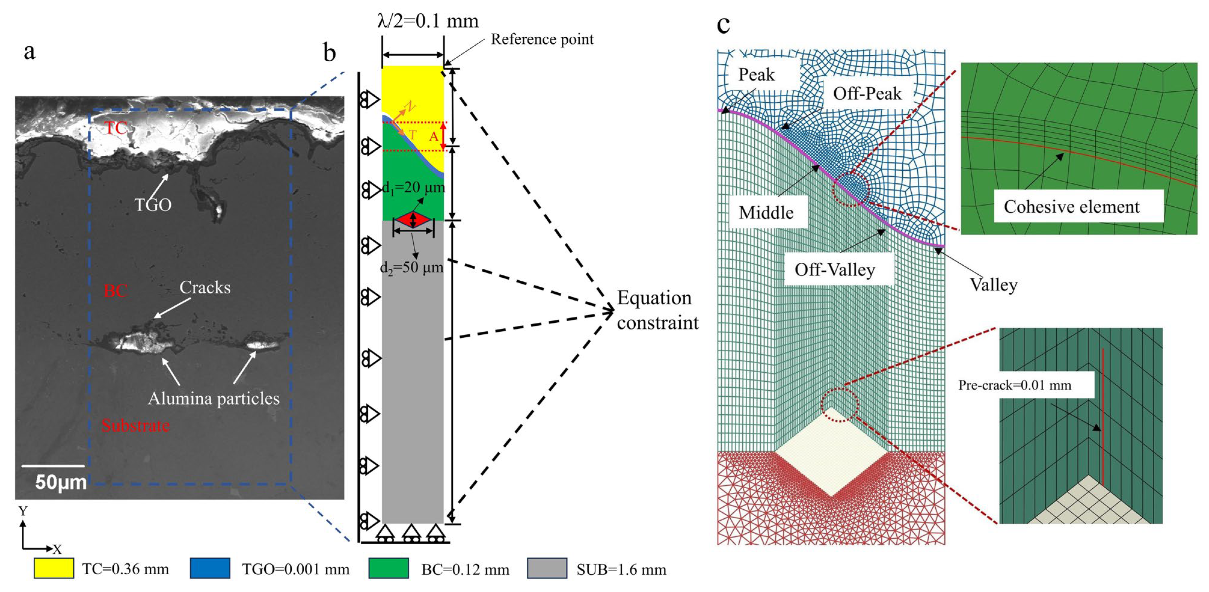
2.1. Geometry Model

The finite element software Abaqus 2022 was used to establish a computational model of the TBCs [18]. While Abaqus 2022 offers some multi-physics capabilities, it may not fully integrate all the relevant physical phenomena in TBCs, such as the coupling between thermal, mechanical, and chemical processes. Under identical boundary conditions, the difference in stress characteristics between 3D and 2D models resides solely in the stress magnitude. To reduce computational costs, a localized 2D planar finite element model was constructed based on the cross-sectional geometry of the TBCs [19,20]. The coating system consisted of four distinct layers from top to bottom: a 0.36 mm thick 8 wt.% yttria-stabilized zirconia (8YSZ) TC, a 0.001 mm thick α-Al2O3 TGO layer, a 0.12 mm thick NiCoCrAlY (MCrAlY) BC, and a 1.6 mm thick Inconel DZ125 SUB. To investigate the crack propagation mechanisms induced by alumina abrasive particles (Al2O3), interfacial residual grit particles were geometrically reconstructed at the SUB/BC interface using Abaqus partition tools. Their morphology was calibrated against cross-sectional SEM images (see Figure 1a), which revealed irregularly flattened particle shapes and an undulating TGO interface. For computational tractability, large grit particles were simplified as rhombic quadrilaterals with diagonals d2 = 50 μm and d1 = 20 μm, while small particles were modeled with d2 = 20 μm and d1 = 15 μm. The TGO interface morphology was approximately characterized by a cosine function with an amplitude of A = 0.03 mm and wavelength λ = 0.2 mm, which has been adopted by many scholars [19,21] (see Figure 2b).

2.2. Boundary Condition and Meshing

As shown in Figure 1b, since the TBC model in this study represented a segment of the entire system, periodic boundary conditions were applied. Symmetry constraints were enforced on the left boundary ( U X = 0 ), while equation constraints synchronized U X displacements between all right boundary nodes and a designated reference node. The bottom boundary was fully constrained in the U y direction to suppress rigid-body motion, whereas the top of the model was not constrained, representing a free surface.
The numerical model adopted a transient, sequentially coupled thermal/mechanical framework to analyze the thermomechanical behavior of the TBCs. During the thermal analysis phase, the whole model domain was discretized using 4-node heat transfer linear quadrilateral elements (DC2D4). For the subsequent mechanical analysis, 4-node bilinear plane strain quadrilateral elements (CPE4) were applied to the TC, TGO layer, BC, and alumina particles, while 3-node linear plane strain triangle (CPE3) elements were used to discretize the SUB. To address TGO growth anisotropy, a sweeping meshing technique generated stratified elements within the 0.001 mm thick TGO layer. Zero-thickness 4-node two-dimensional cohesive elements (COH2D4) were embedded at the BC/TGO interface to simulate interfacial delamination. Additionally, a 0.01 mm vertical pre-crack was introduced near the upper tip of the alumina particle to simulate the subsequent crack propagation within the BC layer. (see Figure 2c).

2.3. Material Property

All material constituents within the TBCs, except for the TGO layer, were modeled as isotropic and homogeneous continua. Since the BC plastic deformation severely influences the stress distribution within TBCs, the BC layer as represented as an elastic/plastic material, with its properties listed in Table 1 [22]. As shown, increasing the temperature led to a significant reduction in the yield strength and plastic strain capacity of the BC layer, which decreased its load-bearing capability and promoted localized plastic deformation. The TC and SUB were assumed to behave as linear elastic materials, as the creep and plastic deformation of the SUB had negligible influence on the TBC’s stress distribution [23,24]. Residual stresses originating from the coating deposition processes, high-temperature phase transformations, and time-dependent creep behavior were not considered in the simulation of any layer. Given the substantial temperature variations that occur during the operational life of TBCs, all material properties were defined as temperature-dependent to improve the accuracy of the simulation. The thermomechanical parameters for each layer are shown in Table 2 [25,26].
The anisotropic growth behavior of the TGO during the dwelling phase was simulated through the Abaqus user subroutine UEXPAN, which imposes growth strains with two orthotropic components: (i) a through-thickness strain normal to the TC/BC interface and (ii) an in-plane strain parallel to the interfacial plane. To reflect the preferential growth in the thickness direction, an anisotropic growth ratio of 0.1 was maintained between the in-plane and through-thickness components per thermal cycle [27]

2.4. Thermal Cycling History

To investigate the evolution of stress distribution and the effect of grit particle size on crack propagation in TBCs under thermal cycling, thermal cycling was applied to the whole model. The initial temperature was set to 20 °C. The cyclic thermal loading of the model is shown in Figure 3. A cycle consisted of three stages: First, the TBC was heated from the initial temperature of 20 °C to 1100 °C within 300 s. Then, the model underwent a 600 s dwelling stage at the peak temperature. Finally, the system was cooled back to 20 °C within 300 s. A total of 20 cycles (N = 20) were applied. The whole model imposed a uniform temperature field and there was no temperature gradient between the layers during the temperature change [9].

2.5. Crack Initiation and Growth Criterion

Interfacial crack propagation in TBCs under thermal cycling can be effectively simulated through the CZM. ABAQUS provides two implementations of the cohesive zone method: surface-based and element-based cohesive behavior [28]. In this study, element-based cohesive behavior was employed to simulate delamination at the BC/TGO interface. As shown in Figure 4, a bilinear traction/separation law was adopted to control the damage initiation and evolution processes at the BC/TGO interface [25], where zero-thickness cohesive elements were embedded. The equations for this constitutive relationship are expressed as
σ i = K δ i δ i max δ i 0 ( 1 D i ) K δ i δ i 0 < δ i max < δ i f ( i = n , s ) 0 δ i max δ i f
where the damage variable D i is defined as
D i = δ i f ( δ i max δ i 0 ) δ i max ( δ i f δ i 0 ) ( i = n , s )
where σ i represents the cohesive traction, and δ i denotes the separation displacement. When the maximum historical separation displacement satisfies δ i max δ i 0 , the material behaves in a linear elastic manner with stiffness K , and the traction increases linearly with displacement. For intermediate separation states where δ i 0 < δ i max < δ i f , interfacial damage initiates and evolves, described by the damage variable D i . Upon reaching δ i max δ i f , the interface is fully degraded and considered to have failed. Here, i = n , s , where n and s represent the normal and first shear directions, respectively; the second shear direction is neglected due to the 2D model assumption. The superscripts 0, f , and max refer to the damage initiation state, complete failure state, and the current maximum separation displacement, respectively. Once D i = 1 , the stiffness of the cohesive element is reduced to zero, and the corresponding element is deleted to simulate crack propagation.
For mixed-mode fracture, the onset of material degradation is characterized using the quadratic nominal stress criterion, which serves as the initial damage initiation criterion and is expressed as
σ n σ n 0 2 + σ s σ s 0 2 = 1
where σ n 0 = 200 MPa and σ s 0 = 100 MPa represent the critical stresses in the normal and first shear directions at the BC/TGO interface, respectively [25]. A power criterion is employed to assess the mixed-mode growth behavior of BC/TGO cracks and is described as
G n G n c α n + G s G s c α s = 1
where G n c = 20 J/m2 and G s c = 60 J/m2 are the critical fracture energies in the normal and shear direction at the BC/TGO interface, respectively. The power law exponents α n and α s are both set to 1.0 [25,29,30]. When the sum of the normal and shear fracture energies satisfies the specified criterion, the cohesive element is deleted, thus allowing crack propagation.
The propagation of internal cracks along an arbitrary path in thermal barrier coatings was simulated using the XFEM [31]. Heterogeneous multilayered and conventional finite element approaches require iterative mesh refinement to accommodate geometric discontinuities, while XFEM circumvents this limitation through nodal enrichment functions and additional degrees of freedom, as originally formulated by Belytschko and Black [32]. In this study, XFEM was applied to the BC layer to simulate the crack evolution under thermal cycling. The maximum principal stress criterion was employed to describe crack propagation at the BC and is expressed as
σ max σ max c = 1
where σ max c = 600 MPa is the critical maximum principal stress of the BC layer [33]. The mixed-mode crack propagation behavior within the BC was governed by a power-law fracture criterion, which is formulated as
G n G n c α n + G s G s c α s = 1
where G n c and G s c denote the critical fracture energies required to cause failure in the normal and first shear directions, respectively. The exponent was set to 1, assuming an isotropic distribution of fracture energy in which all directional components shared a uniform critical value of 50 J/m2 [34].

3. Results and Discussion

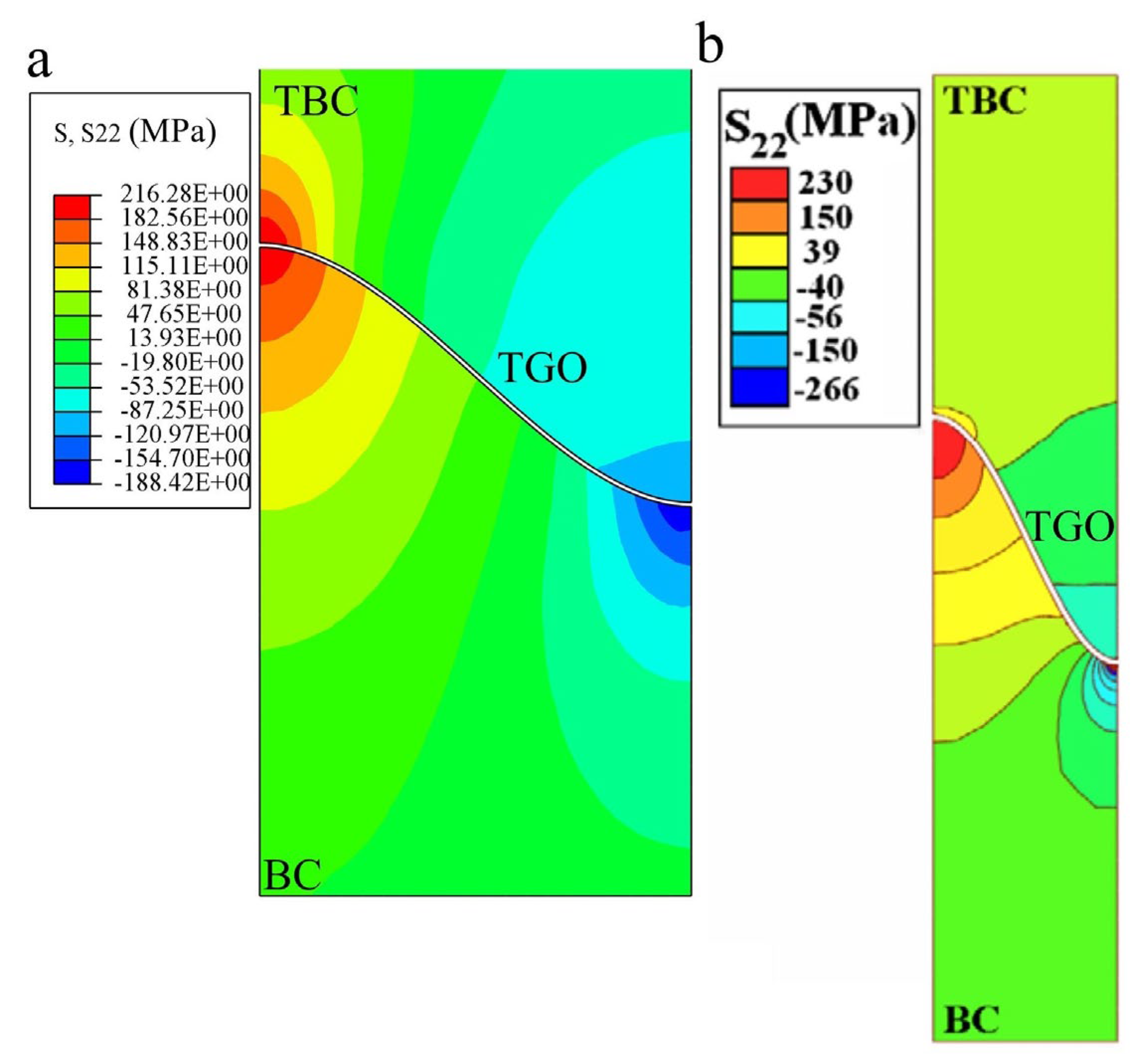
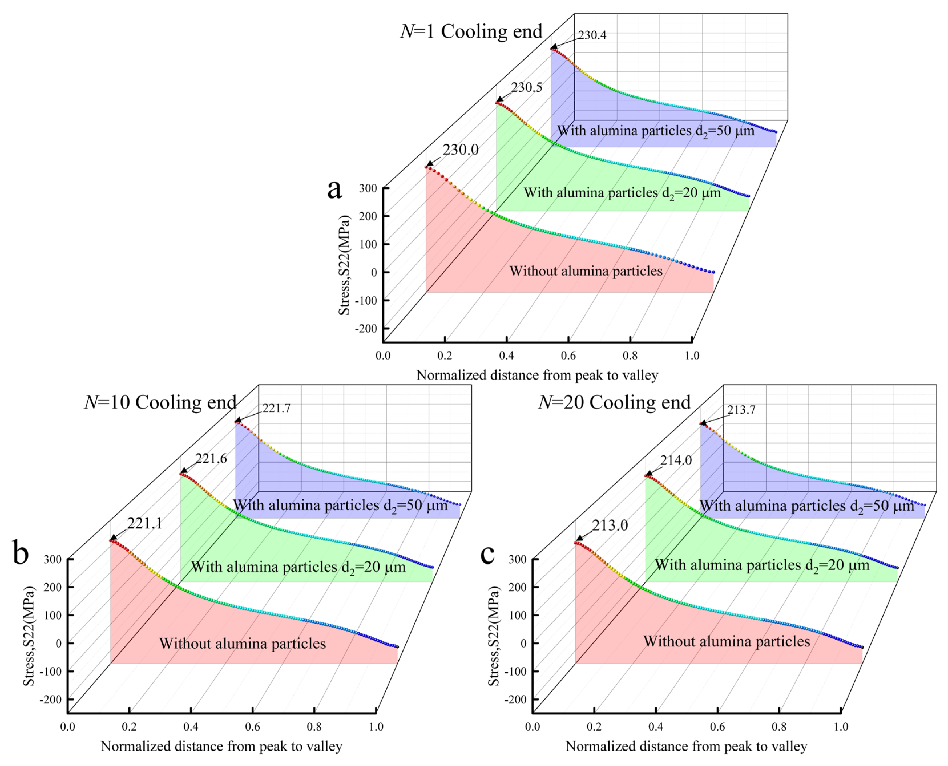
3.1. Stress Distribution During Thermal Cycling

The evolution of internal stresses during thermal cycling significantly influences the spatial distribution of potential crack nucleation sites. Therefore, analyzing the stress evolution characteristics within the coating is critical. Radial tensile stress (S11) and normal tensile stress (S22) are the main contributors to mode I fracture. S22 promotes the growth of horizontally oriented cracks, while positive S11 drives the propagation of vertically oriented cracks [35].
To elucidate the effect of grit-blasting-induced residual abrasive particles on interfacial and internal crack evolution, this section focuses on the evolution of S22 at the BC/TGO interface and S11 within the BC layer under varying sizes of alumina inclusions embedded at the SUB/BC interface.
To validate the accuracy and reliability of the established computational model, a grit-free interface configuration was constructed under identical boundary conditions as those employed by Ranjbar et al. [36]. As shown in Figure 5, a comparative analysis indicated that the S22 stress distributions of both models were nearly identical after cooling to 20 °C following thermal cycling. The observed thermomechanical mismatch near the interface arose from differences in thermal expansion coefficients between the constituent layers, leading to tensile stress concentrations at the interface peak in both the TC and BC layers and compressive stress accumulations at the valley. Minor discrepancies in stress magnitudes were mainly attributed to differences in the material properties, interface geometry (such as TGO amplitude and wavelength), and physical assumptions—including the consideration of creep in Ranjbar’s model versus TGO growth model in the present study—as well as differences in meshing strategies, such as the use of quadratic triangular elements with generalized plane strain approximation in Ranjbar’s work. This agreement confirmed the validity of the current boundary condition settings and ensured the robustness of the model for simulating crack propagation behavior in the subsequent grit-inclusion scenarios.
Crack propagation in TBCs is predominantly induced during the cooling phase of thermal cycling due to the accumulation of thermomechanical stresses [36,37]. In this study, particular attention was given to the evolution of S22 stress at the BC/TGO interface during cooling termination across multiple thermal cycles. The analysis focused on how the presence of and size variation in grit-blasting-induced interfacial alumina particles influenced the stress distribution
Figure 6 illustrates the S22 stress distribution at the BC/TGO interface after 1, 10, and 20 thermal cycles under different interfacial configurations. Positive values denote tensile stresses, whereas negative values signify compressive stresses. As shown in Figure 6a–c, under conditions without alumina particles, the tensile stress at the interface peak decreased from 230 MPa (N = 1) to 213 MPa (N = 20). This trend is attributed to the interplay between TGO-growth-induced stress buildup and stress relaxation caused by accumulated plastic deformation in the BC layer [38,39], with the latter effect becoming increasingly dominant as the number of thermal cycles increased. Further comparative analysis of the stress distribution curves in Figure 6a–c, considering various grit particles sizes, reveals that, regardless of the size of the grit particles, the BC/TGO interface consistently exhibited higher tensile stresses at the peak and compressive stresses at the valley, with stress magnitudes remaining nearly identical across cases. This indicates that the presence of grit particles had a limited effect on the overall stress distribution at the interface. Moreover, delamination cracks at the BC/TGO interface were more likely to develop at the peak regions, primarily driven by localized stress concentrations rather than the influence of grit particles.
Figure 7 presents the S11 stress distribution within the BC layer following the end of cooling for 1, 10, and 20 thermal cycles in the model. Comparative analysis of Figure 7a–c (grit-free interface) and Figure 7d–f (grit-inclusion interface) reveals that the embedment of grit particles at the SUB/BC interface during bond coat deposition induced irregular deformation zones. These zones generated interfacial discontinuities that acted as stress concentrators near the grit particle tips within the BC layer. As thermal cycling progressed, these localized stress concentrations became increasingly severe, with the maximum tensile stress in the BC layer increasing significantly from 55.18 MPa (see Figure 7c) to 640.18 MPa (see Figure 7f).
As shown in Figure 7d–i, tensile stresses were localized near the upper tip of the grit particles within the BC layer, while compressive stresses developed along the lateral grit surfaces. This stress distribution pattern indicates that the upper grit tip is a location where crack propagation is likely to begin, driven by localized tensile stress concentrations. Under the influence of interfacial grit particle embedment, the S11 stress in the BC layer exhibited a non-monotonic trend: it increased over the first 10 thermal cycles and subsequently decreased. In the early stages of thermal cycling, the accumulation of thermally induced mismatch stresses at the grit tips dominated over the limited plastic stress relaxation in the BC layer. However, after approximately 10 cycles, the accumulated plastic deformation became significant enough to relieve the stress concentration, thereby suppressing further crack propagation.
Further comparative analysis of the effect of grit particle size on the BC layer stress distribution (see Figure 7d–i) reveals that after one thermal cycle (N = 1), increasing the grit size from d2 = 20 μm to 50 μm increased the maximum tensile stress from 413.77 MPa to 465.83 MPa, with simultaneous expansion of the tensile stress distribution zones. As thermal cycling progressed, the stress difference between the two grit sizes became more pronounced, demonstrating that larger grit particles intensified stress concentrations within the BC layer. This enhanced stress concentration facilitated the propagation of vertical cracks at the grit particle/BC interface.

3.2. Effect of Grit Particles on BC/TGO Interfacial Crack Propagation

Stress analysis of a coating can only identify regions with high tensile stress where cracks are likely to begin propagating, and this indicates the general trend of crack growth. However, it does not provide precise information about the actual crack path or the extent of propagation. To more intuitively reveal the influence of grit particle sizes on crack extension at the BC/TGO interface, cohesive elements were inserted at the BC/TGO interface to extract and compare the overall scale stiffness degradation (SDEG) and crack length under different grit particle sizes. As shown in Figure 8a, after 20 thermal cycles, varying degrees of damage were observed along the BC/TGO interface from the peak to the valley. An SDEG value of 1 indicates complete failure of the element, while 0 indicates no damage. It can be seen from Figure 8a that the SDEG value was 1 in the region near the peak of the BC/TGO interface (normalized distance approximately 0~0.25), followed by a sharp drop in the range to about 0.25~0.3, and remaining at 0 beyond that. This suggests that interfacial cracks developed at the peak and gradually propagated toward the near-peak region, but were arrested as they approached the middle region of the interface. These crack evolution characteristics are consistent with the findings of Jiang et al. [26], who similarly reported interfacial crack propagation originating from peak regions induced by TGO growth under thermal cycling.
Further analysis was conducted to investigate the evolution of BC/TGO interfacial crack length during thermal cycling under the influence of grit particle size. As shown in Figure 8b, the interfacial crack propagated rapidly during the first two thermal cycles, then gradually slowed and stabilized after the fourth cycle, ultimately reaching a final crack length of approximately 0.03 mm. These results indicate that neither the crack propagation rate nor the final crack length at the BC/TGO interface was significantly affected by the size of embedded grit particles. The rapid crack extension observed in the early stages of thermal cycling was accompanied by a swift release of local stress at the BC/TGO interface, resulting in a progressive reduction in the stress concentration region. Consequently, the local stress driving crack growth diminished with each cycle. Once the driving force for crack growth became balanced by the fracture resistance of the material, further crack propagation was suppressed.
The numerical results confirmed that grit particle size exerted minimal influence on the stress distribution at the BC/TGO interface, which is consistent with the physical expectation due to the spatial separation from the BC/SUB interface. Interfacial delamination cracks consistently developed at the interface peaks, driven predominantly by localized tensile stress concentrations rather than by the presence of residual grit particles.

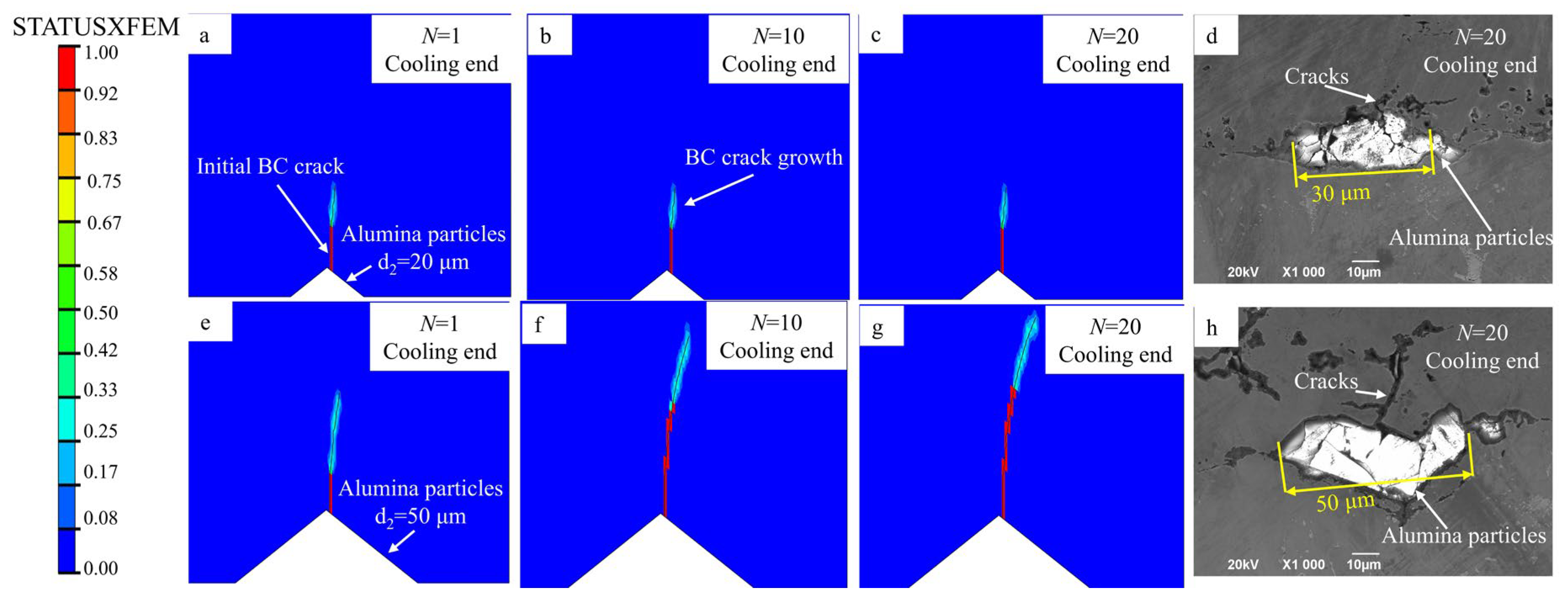
3.3. Effect of Grit Particles on Crack Propagation Within the BC Layer

As shown in Figure 7, the S11 distribution in the BC layer after 20 thermal cycles indicated that grit particles embedded at the SUB/BC interface induced significant stress concentrations in the BC layer near the particle sites. These localized stresses contributed to crack propagation within the BC layer during thermal cycling, with more pronounced surface cracks observed around larger grit particles. To further investigate the effect of grit particle size on crack propagation within the BC layer during thermal cycling, numerical simulations were conducted.
Although actual materials contain micro-defects, the initial geometry in our simulation was defined without any predefined cracks and was used solely for stress analysis. This allowed the identification of high-risk regions where localized tensile stress concentrations occurred. After these potential damage initiation sites were identified, a short pre-crack (0.01 mm) was introduced in a second-stage simulation using XFEM, specifically to model crack propagation under thermal cycling conditions. As described in Figure 2c, a 0.01 mm long vertical pre-crack was introduced within the BC layer near the upper tip of the embedded grit particle. The BC layer was modeled as an enriched element region, where a value of 1 for the enriched element status (STATUSXFEM) indicates complete fracture, and a value of 0 indicates an intact element.
With increasing thermal cycles, the propagation behavior of cracks within the BC layer was affected by the size of the embedded grit particles. Comparative analysis of Figure 9a–c,e–g shows that when the grit particle size was d2 = 20 μm, cracks began to propagate within the BC layer near the upper tip of the embedded grit particle, where tensile stress concentration occurred at the end of the first cooling cycle. The crack then extended vertically to a limited extent. In the subsequent thermal cycles, crack growth was significantly suppressed. In contrast, when the grit particle size was increased to d2 = 50 μm, the larger particles induced a broader stress concentration zone within the BC layer, resulting in progressive crack propagation from the initial pre-crack upward toward the geometric valley of the BC/TGO interface during thermal cycling.
To further compare the effects of different grit particle sizes on the evolution of crack length and propagation rate within the BC layer during thermal cycling, the results are shown in Figure 10. As shown, when the grit particle size was d2 = 20 µm, the crack within the BC layer rapidly grew during the first thermal cycle, then remained stable in length throughout the subsequent cycles. This was due to the redistribution and partial relaxation of tensile stress around the crack tip, which reduced the local driving force for further extension. This behavior is consistent with the crack evolution observed in Figure 9a–c.
In contrast, under the condition of a grit particle size d2 = 50 μm, cracks within the BC layer started to grow earlier than in the case with smaller grit particles, although the crack length remained comparable to that of the small-particle case during the first 0.5 thermal cycles. However, after the tenth thermal cycle, the crack propagation rate decreased significantly, with the final crack length reaching approximately 0.056 mm.
These results indicate that larger grit particles introduced more extensive and intense stress concentrations within the BC layer, leading to earlier onset of crack propagation and longer crack lengths. Nevertheless, in the later stages of thermal cycling, the redistribution of stress due to prior crack extension and accumulated plastic deformation in the BC layer reduced the local energy driving crack growth, thereby suppressing further propagation according to the mixed-mode energy-based damage criterion. The simulation results are in good agreement with the experimental observations.

4. Conclusions

In this study, a crack propagation model was developed to investigate the effect of grit-blasting-induced residual abrasive particles at the SUB/BC interface on the crack evolution behavior of TBCs under thermal cycling, using the CZM and XFEM. The influence of grit particle size on stress evolution at the interface and within the BC layer, as well as crack propagation patterns, was quantitatively evaluated. The main conclusions are as follows:
1. The size of grit particles embedded at the SUB/BC interface had negligible influence on the stress distribution and crack propagation behavior at the BC/TGO interface. This was primarily due to the spatial separation between the two interfaces.
2. The presence of grit particles induced localized tensile stress concentrations in the BC layer near the particle tip, which promoted vertical crack propagation in this region. As thermal cycling progressed, these cracks tended to extend upward through the BC layer toward the BC/TGO interface.
3. Larger grit particle sizes led to higher tensile stress concentrations and longer vertical cracks within the BC layer, making early-stage coating failure more likely. When the grit size was increased from 20 μm to 50 μm, the peak tensile stress in the BC layer increased significantly, resulting in longer final crack lengths. However, in later thermal cycles, crack growth was gradually suppressed due to stress relief and accumulated plastic deformation.
It is noted that the present model does not account for crack propagation through grit particles or into the substrate. Although such behavior is observed in SEM images, this study focused on the surface cracking behavior in the BC layer to isolate the dominant damage mechanisms. These additional crack paths will be addressed in future studies, to provide a more comprehensive understanding.

Author Contributions

Conceptualization, Z.J., Q.L., J.L. and J.Y.; Methodology, X.S. and Z.W.; Software, D.L., X.G., Q.L. and F.Z.; Validation, Z.J.; Formal analysis, Q.L.; Investigation, X.S. and Z.W.; Resources, J.Z.; Data curation, X.S. and Z.W.; Writing—original draft, X.S.; Writing—review & editing, X.S., Z.W., Z.J., J.Z., D.L., X.G. and F.Z.; Visualization, D.L., X.G. and F.Z.; Supervision, Z.J., J.Z., J.L. and J.Y.; Project administration, J.Z.; Funding acquisition, J.L. All authors have read and agreed to the published version of the manuscript.

Funding

The authors are grateful for financial support from the Sichuan Science and Technology Program [Grant No. 2024NSFSC2014, 2024NSFTD0019, 2024ZDZX0039], the Open Research Project of State Key Laboratory of Clean and Efficient Turbomachinery Power Equipment (DEC8300CG202319357EE280491), the Open Fund Project of National United Engineering Laboratory for Advanced Bearing Tribology (No. 202402), the Postgraduate Innovation Fund Project by Southwest University of Science and Technology (No. 24ycx3010), the Doctoral Scientific Research Foundation of Hubei University of Automotive Technology (BK202468), and the construction project of the Fujiang Laboratory Nuclear Medicine Artificial Intelligence Research Center (No. 2023ZYDF074).

Institutional Review Board Statement

Not applicable.

Informed Consent Statement

Not applicable.

Data Availability Statement

Data are contained within the article.

Conflicts of Interest

The authors declare no conflicts of interest.

References

  1. Long, H.; Mao, S.; Liu, Y.; Zhang, Z.; Han, X. Microstructural and compositional design of Ni-based single crystalline superalloys―A review. J. Alloys Compd. 2018, 743, 203–220. [Google Scholar] [CrossRef]
  2. Padture, N.P.; Gell, M.; Jordan, E.H. Thermal Barrier Coatings for Gas-Turbine Engine Applications. Science 2002, 296, 280–284. [Google Scholar] [CrossRef] [PubMed]
  3. Clarke, D.R.; Oechsner, M.; Padture, N.P. Thermal-barrier coatings for more efficient gas-turbine engines. MRS Bull. 2012, 37, 891–898. [Google Scholar] [CrossRef]
  4. Thakare, J.G.; Pandey, C.; Mahapatra, M.M.; Mulik, R.S. Thermal Barrier Coatings—A State of the Art Review. Met. Mater. Int. 2021, 27, 1947–1968. [Google Scholar] [CrossRef]
  5. Liu, K.; Du, Y.; Guo, X.; Ma, J.; He, W.; Cao, Y.; Du, J. Study of stress-driven cracking behavior and competitive crack growth in functionally graded thermal barrier coatings. Surf. Coat. Technol. 2023, 473, 129969. [Google Scholar] [CrossRef]
  6. Ranjbar-far, M.; Absi, J.; Mariaux, G.; Smith, D.S. Crack propagation modeling on the interfaces of thermal barrier coating system with different thickness of the oxide layer and different interface morphologies. Mater. Des. 2011, 32, 4961–4969. [Google Scholar] [CrossRef]
  7. Wei, Z.; Cai, H.; Feng, R.; Zhang, H. The Combined Effect of Creep and TGO Growth on the Cracking Driving Force in a Plasma-Sprayed Thermal Barrier System. J. Therm. Spray Technol. 2019, 28, 1000–1016. [Google Scholar] [CrossRef]
  8. Abdelgawad, A.; Al-Athel, K.; Albinmousa, J. Analysis of crack initiation and propagation in Thermal Barrier Coatings using SEM-Based geometrical model with extended finite element method. Ceram. Int. 2021, 47, 33140–33151. [Google Scholar] [CrossRef]
  9. Shi, D.; Song, J.; Li, S.; Qi, H.; Yang, X. Cracking behaviors of EB-PVD thermal barrier coating under temperature gradient. Ceram. Int. 2019, 45, 18518–18528. [Google Scholar] [CrossRef]
  10. Mohammadi, Z.; Ziaei-Moayyed, A.A.; Mesgar, A.S.-M. Grit blasting of Ti–6Al–4V alloy: Optimization and its effect on adhesion strength of plasma-sprayed hydroxyapatite coatings. J. Mater. Process. Technol. 2007, 194, 15–23. [Google Scholar] [CrossRef]
  11. Moreau, C.; Gougeon, P.; Lamontagne, M. Influence of substrate preparation on the flattening and cooling of plasma-sprayed particles. J. Therm. Spray Technol. 1995, 4, 25–33. [Google Scholar] [CrossRef]
  12. Giouse, J.B.; White, K.; Tromas, C. Nanoindentation characterization of the surface mechanical properties of a 17-4PH stainless steel substrate treated with grit blasting and coated with a Cr3C2-NiCr coating. Surf. Coat. Technol. 2019, 368, 119–125. [Google Scholar] [CrossRef]
  13. Nowak, W.J.; Ochał, K.; Wierzba, P.; Gancarczyk, K.; Wierzba, B. Effect of Substrate Roughness on Oxidation Resistance of an Aluminized Ni-Base Superalloy. Metals 2019, 9, 782. [Google Scholar] [CrossRef]
  14. Abbas, M.; Smith, G.M.; Munroe, P.R. Microstructural study of HVOF sprayed Ni particles on a grit-blasted stainless-steel substrate. Surf. Coat. Technol. 2021, 409, 126832. [Google Scholar] [CrossRef]
  15. Hernández, L.; Oliveira, F.; Berríos, J.A.; Villalobos, C.; Pertuz, A.; Puchi Cabrera, E.S. Fatigue properties of a 4340 steel coated with a Colmonoy 88 deposit applied by high-velocity oxygen fuel. Surf. Coat. Technol. 2000, 133–134, 68–77. [Google Scholar] [CrossRef]
  16. Antoš, J.; Duliškovič, J.; Bejblíková, S. Aluminium oxide grid blasting: Grid size and blasting pressure influence on the substrate surface contamination, roughness and ceramic plasma spray coating adhesion strength. J. Phys. Conf. Ser. 2023, 2572, 012009. [Google Scholar] [CrossRef]
  17. Lai, J.; Shen, X.; Yuan, X.; Li, D.; Gong, X.; Zhao, F.; Liao, X.; Yu, J. The Effect of Shot Blasting Abrasive Particles on the Microstructure of Thermal Barrier Coatings Containing Ni-Based Superalloy. Coatings 2024, 14, 1312. [Google Scholar] [CrossRef]
  18. ABAQUS Analysis User’s Guide, version 6.22; Dassault Systèmes: Vélizy-Villacoublay, France, 2022; Available online: https://help.3ds.com/HelpProductsDS.aspx (accessed on 20 June 2025.).
  19. Cen, L.; Qin, W.; Yu, Q. A three-dimensional finite element model for the oxide growth mechanism and growth-induced stress within thermal barrier system. Mater. Today Commun. 2021, 29, 102790. [Google Scholar] [CrossRef]
  20. Wei, Z.; Liu, Y.; Cheng, B.; Tahir, A. Influence of non-uniform feature of thermally grown oxide thickness on the local stress state and cracking behavior in TBC. Surf. Coat. Technol. 2022, 443, 128607. [Google Scholar] [CrossRef]
  21. Xiao, Y.Q.; Yang, L.; Zhu, W.; Zhou, Y.C.; Pi, Z.P.; Wei, Y.G. Delamination mechanism of thermal barrier coatings induced by thermal cycling and growth stresses. Eng. Fail. Anal. 2021, 121, 105202. [Google Scholar] [CrossRef]
  22. Aktaa, J.; Sfar, K.; Munz, D. Assessment of TBC systems failure mechanisms using a fracture mechanics approach. Acta Mater. 2005, 53, 4399–4413. [Google Scholar] [CrossRef]
  23. Song, J.; Qi, H.; Shi, D.; Yang, X.; Li, S. Effect of non-uniform growth of TGO layer on cracking behaviors in thermal barrier coatings: A numerical study. Surf. Coat. Technol. 2019, 370, 113–124. [Google Scholar] [CrossRef]
  24. Yu, Q.M.; Zhou, H.L.; Wang, L.B. Influences of interface morphology and thermally grown oxide thickness on residual stress distribution in thermal barrier coating system. Ceram. Int. 2016, 42, 8338–8350. [Google Scholar] [CrossRef]
  25. Białas, M. Finite element analysis of stress distribution in thermal barrier coatings. Surf. Coat. Technol. 2008, 202, 6002–6010. [Google Scholar] [CrossRef]
  26. Jiang, J.; Wang, W.; Zhao, X.; Liu, Y.; Cao, Z.; Xiao, P. Numerical analyses of the residual stress and top coat cracking behavior in thermal barrier coatings under cyclic thermal loading. Eng. Fract. Mech. 2018, 196, 191–205. [Google Scholar] [CrossRef]
  27. Wei, Z.; Cai, H.; Li, C. Comprehensive dynamic failure mechanism of thermal barrier coatings based on a novel crack propagation and TGO growth coupling model. Ceram. Int. 2018, 44, 22556–22566. [Google Scholar] [CrossRef]
  28. Bostancı, S.M.; Gürses, E.; Çöker, D. Finite Element Modelling of TBC Failure Mechanisms by Using XFEM and CZM. Procedia Struct. Integr. 2019, 21, 91–100. [Google Scholar] [CrossRef]
  29. Zhu, W.; Zhang, Z.B.; Yang, L.; Zhou, Y.C.; Wei, Y.G. Spallation of thermal barrier coatings with real thermally grown oxide morphology under thermal stress. Mater. Des. 2018, 146, 180–193. [Google Scholar] [CrossRef]
  30. Fartash, A.H.; Lyavoli, H.F.; Poursaeidi, E.; Schmauder, S. Interfacial delamination of porous thermal barrier coatings based on SEM image processing in finite element model. Theor. Appl. Fract. Mech. 2023, 125, 103915. [Google Scholar] [CrossRef]
  31. Wang, L.; Li, D.C.; Yang, J.S.; Shao, F.; Zhong, X.H.; Zhao, H.Y.; Yang, K.; Tao, S.Y.; Wang, Y. Modeling of thermal properties and failure of thermal barrier coatings with the use of finite element methods: A review. J. Eur. Ceram. Soc. 2016, 36, 1313–1331. [Google Scholar] [CrossRef]
  32. Belytschko, T.; Black, T.A. Elastic crack growth in finite elements with minimal remeshing. Int. J. Numer. Methods Eng. 1999, 45, 601–620. [Google Scholar] [CrossRef]
  33. Zhou, Q.Q.; Yang, L.; Luo, C.; Chen, F.W.; Zhou, Y.C.; Wei, Y.G. Thermal barrier coatings failure mechanism during the interfacial oxidation process under the interaction between interface by cohesive zone model and brittle fracture by phase-field. Int. J. Solids Struct. 2021, 214–215, 18–34. [Google Scholar] [CrossRef]
  34. Li, B.; Fan, X.; Okada, H.; Wang, T. Mechanisms governing the failure modes of dense vertically cracked thermal barrier coatings. Eng. Fract. Mech. 2018, 189, 451–480. [Google Scholar] [CrossRef]
  35. Ranjbar-Far, M.; Absi, J.; Shahidi, S.; Mariaux, G. Impact of the non-homogenous temperature distribution and the coatings process modeling on the thermal barrier coatings system. Mater. Des. 2011, 32, 728–735. [Google Scholar] [CrossRef]
  36. Ranjbar-Far, M.; Absi, J.; Mariaux, G.; Dubois, F. Simulation of the effect of material properties and interface roughness on the stress distribution in thermal barrier coatings using finite element method. Mater. Des. 2010, 31, 772–781. [Google Scholar] [CrossRef]
  37. Rösler, J.; Bäker, M.; Aufzug, K. A parametric study of the stress state of thermal barrier coatings: Part I: Creep relaxation. Acta Mater. 2004, 52, 4809–4817. [Google Scholar] [CrossRef]
  38. Wei, Z.; Cai, Y.; Li, F.; Huang, H.; Wang, M. Heterogeneous multilayered delamination of thermally grown oxide accelerating spallation of thermal barrier coatings. Ceram. Int. 2024, 50, 49300–49310. [Google Scholar] [CrossRef]
  39. Bäker, M.; Rösler, J.; Heinze, G. A parametric study of the stress state of thermal barrier coatings Part II: Cooling stresses. Acta Mater. 2005, 53, 469–476. [Google Scholar] [CrossRef]
Figure 1. (a) Cross-sectional SEM image of TBCs after thermal cycling. (bf) Elemental mapping of interfacial microstructure of the TBCs.
Coatings 15 00747 g001
Figure 2. Geometry and meshing of the model: (a) highly magnified scanning electron microscopy (SEM) image of the TBCs after thermal cycling; (b) geometric characterization with boundary conditions; (c) finite element method mesh.
Coatings 15 00747 g002
Figure 3. Thermal cycling load.
Coatings 15 00747 g003
Figure 4. Bilinear traction separation law.
Coatings 15 00747 g004
Figure 5. Comparing normal stress after 20 thermal cycles: (a) current model simulation; (b) results from Ranjbar [36].
Coatings 15 00747 g005
Figure 6. Comparison of S22 stress distribution along the normalized BC/TGO interface for different alumina particle sizes at the end of thermal cycling: (a) N = 1; (b) N = 10; (c) N = 20.
Coatings 15 00747 g006
Figure 7. Radial stress (S11) distribution in the BC layer during thermal cycling for different alumina particle sizes: (ac) without alumina particles; (df) alumina particle d2 = 20 μm; (gi) alumina particle d2 = 50 μm.
Coatings 15 00747 g007
Figure 8. Quantitative analysis of the effect of alumina particle size on interfacial crack propagation at the BC/TGO interface: (a) SDEG distribution along the normalized BC/TGO interface after 20 thermal cycles; (b) BC/TGO interfacial crack length vs. thermal cycles.
Coatings 15 00747 g008
Figure 9. Evolution of BC surface crack propagation with different alumina particle sizes during thermal cycling: (ad) small alumina particles; (eh) large alumina particles.
Coatings 15 00747 g009
Figure 10. BC surface crack length vs. thermal cycles with different sized alumina particles.
Coatings 15 00747 g010
Table 1. Plastic parameters of bond coat (MCrAlY).
Plastic ParametersTemperature/(°C)
4006008009001000
σ/(Mpa)110025001100220030038045601015
εp00.2300.3000.0200.0200.01
Table 2. Thermal/mechanical properties of TBC.
MaterialTemperature/
(°C)
Elastic Modulus/
(GPa)
μDensity/
(kg∙m−3)
CTE/
10−6∙°C−1
TC (8YSZ)20480.1052809.0
200470.1052809.2
600400.10528010.1
800340.11528010.8
1100220.12528012.2
BC (MCrAlY)202000.30810013.6
2001900.30810014.2
6001600.31810015.2
8001450.32810016.1
11001100.35810017.6
TGO (α-Al2O3)204000.2340008.0
2003900.2340008.2
6003700.3240008.7
8003550.3240009.0
11003200.3340009.6
SUB (Inconel DZ125)202200.31820014.8
2002100.32820015.2
6001700.33820016.2
8001550.34820016.9
11001200.35820018.0
Alumina particle (Al2O3)203800.2738,7005.08
2203690.2738,7005.90
4203700.2738,7006.73
6203550.2738,7007.55
10203200.2738,7009.20
Disclaimer/Publisher’s Note: The statements, opinions and data contained in all publications are solely those of the individual author(s) and contributor(s) and not of MDPI and/or the editor(s). MDPI and/or the editor(s) disclaim responsibility for any injury to people or property resulting from any ideas, methods, instructions or products referred to in the content.

