
Assessing the Printability of Rene 65 Powder for Repairing Degraded GTD 111 Gas Turbine Blades Using L-DED and L-PBF

 , , and
Abstract
1. Introduction
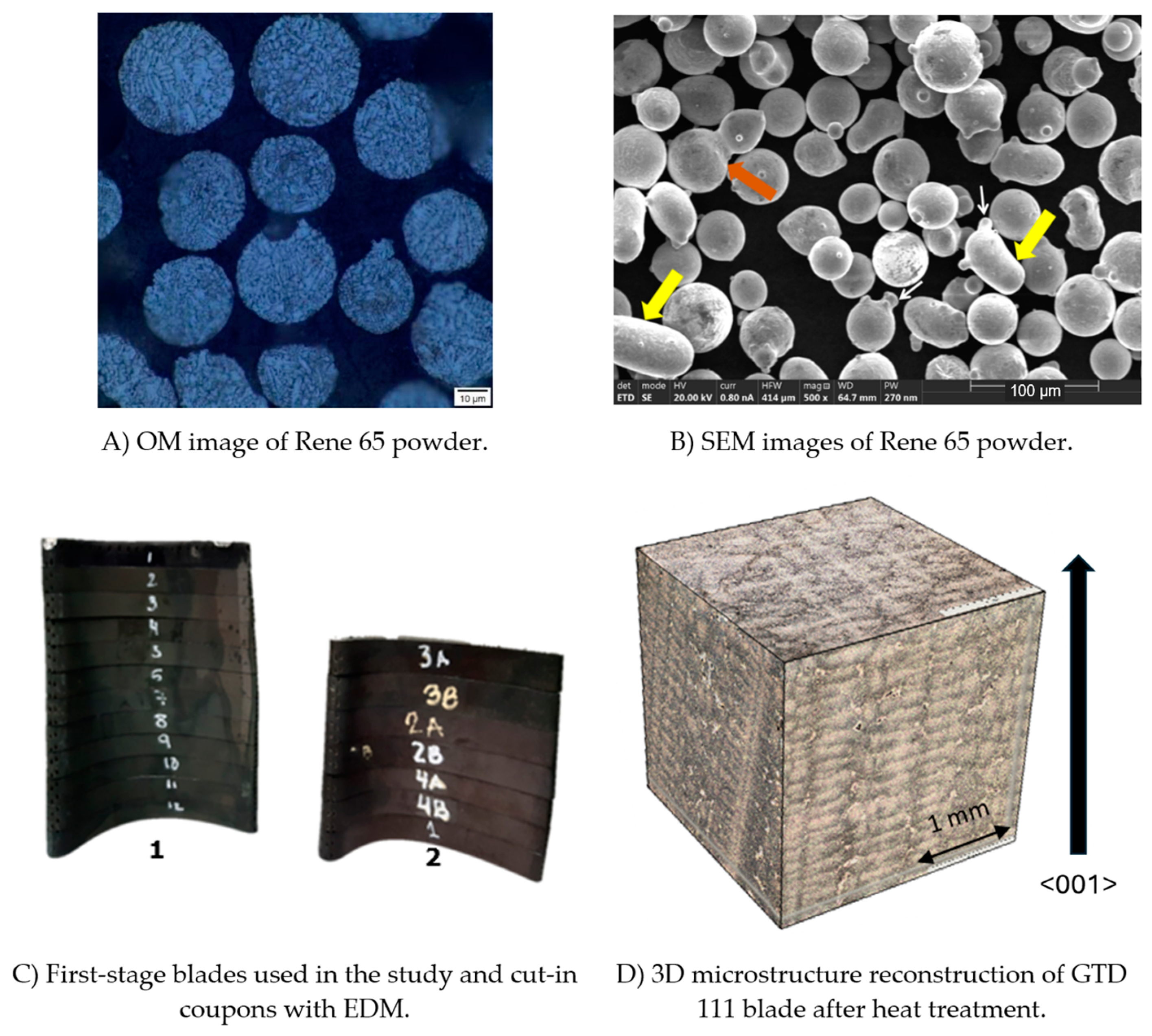
2. Materials and Methods
2.1. L-DED
2.2. L-PBF
3. Results and Discussion
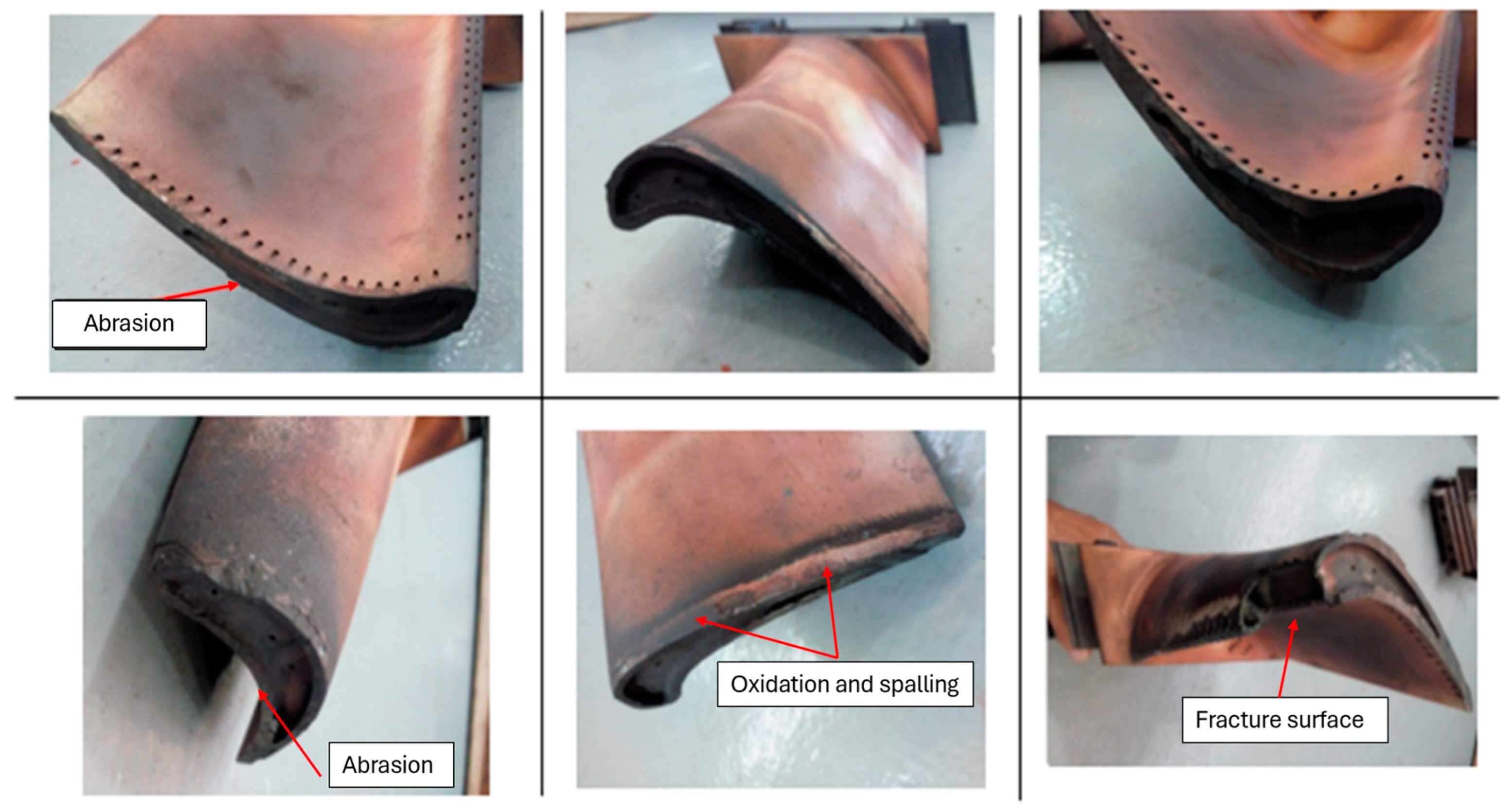
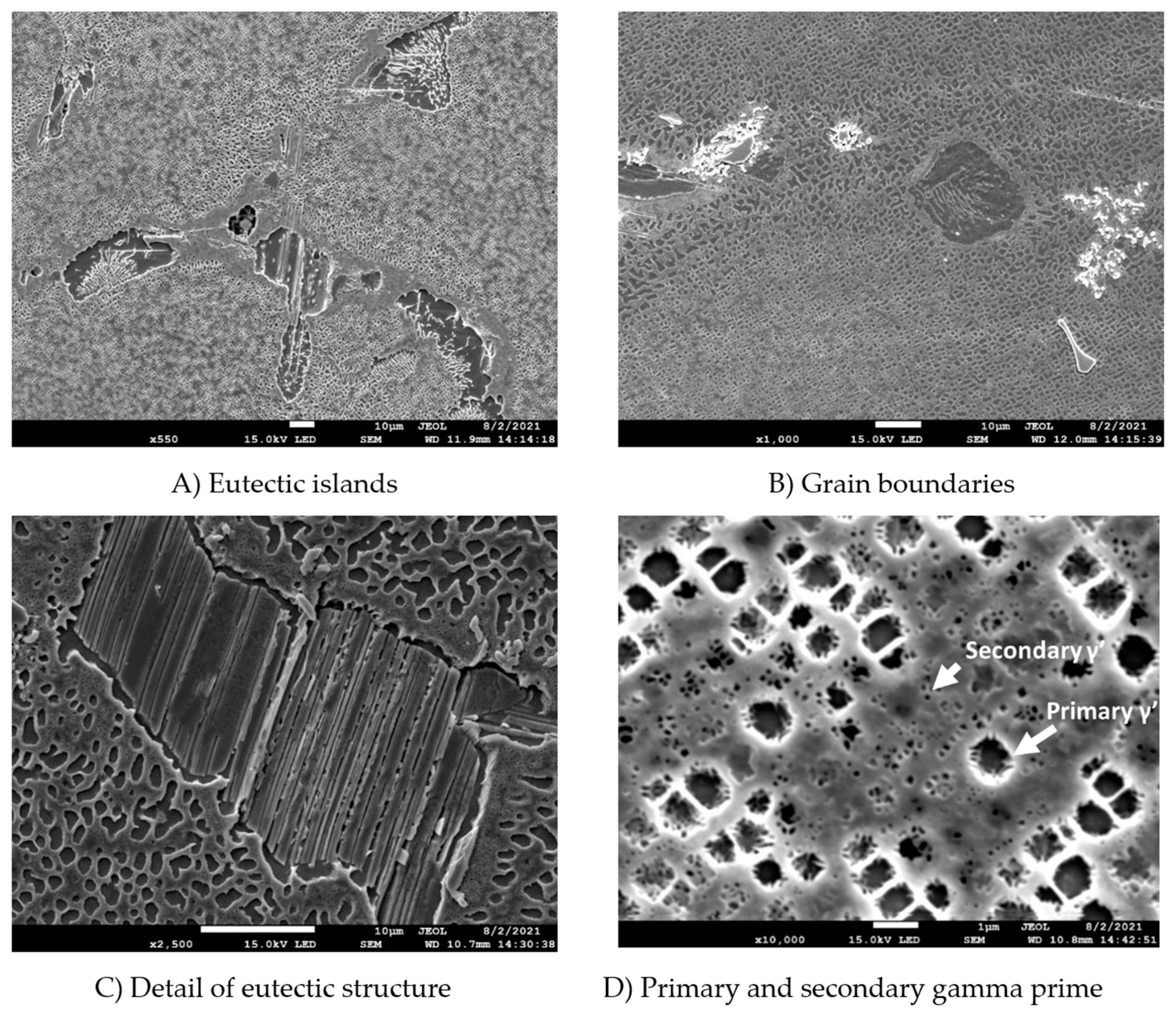
3.1. Characterization of Degraded, Post-Service Blades
3.2. L-DED Manufacturing
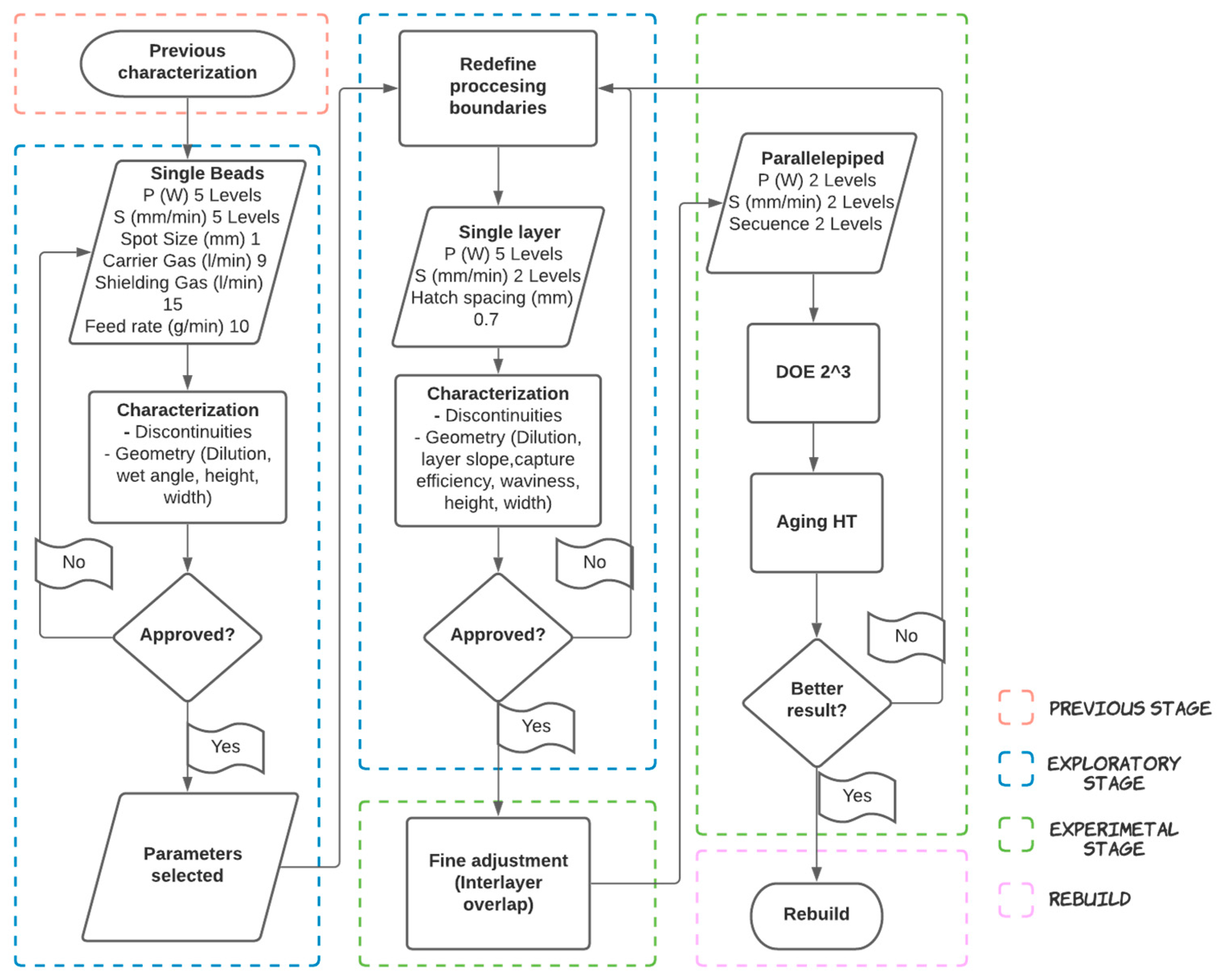
3.2.1. Experimental Stage
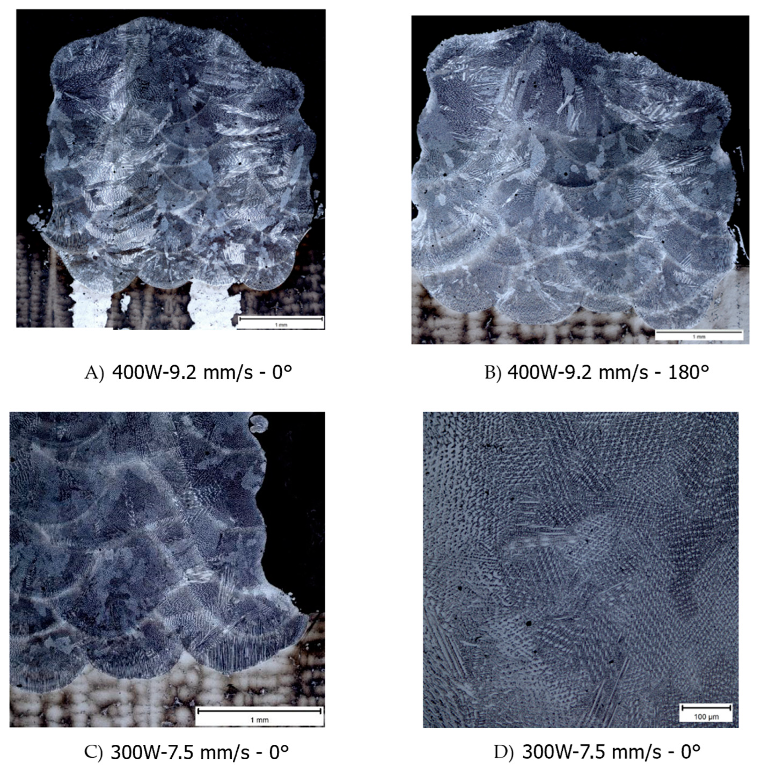
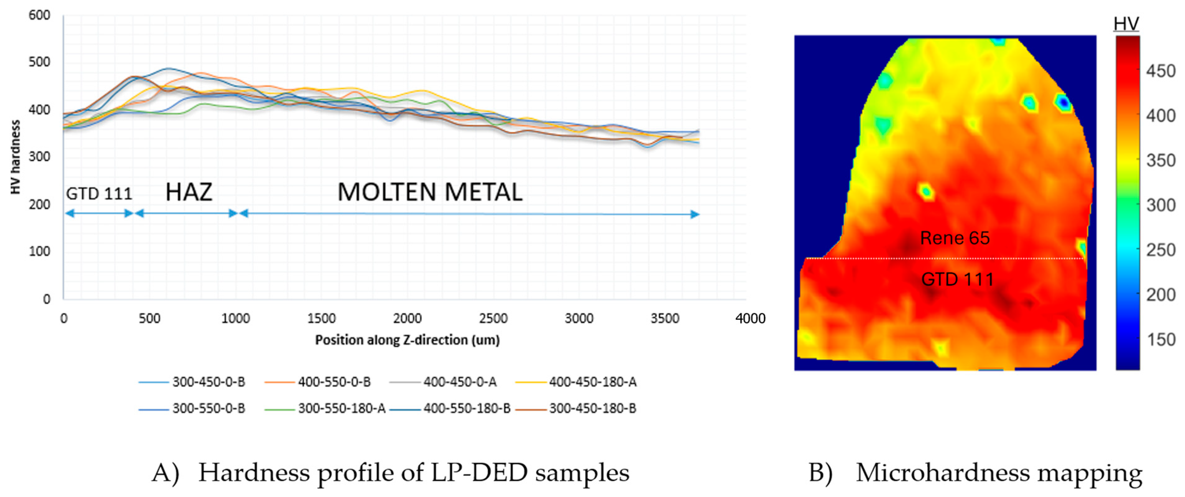
3.2.2. Wall-Tip Repair
3.3. L-PBF Manufacturing
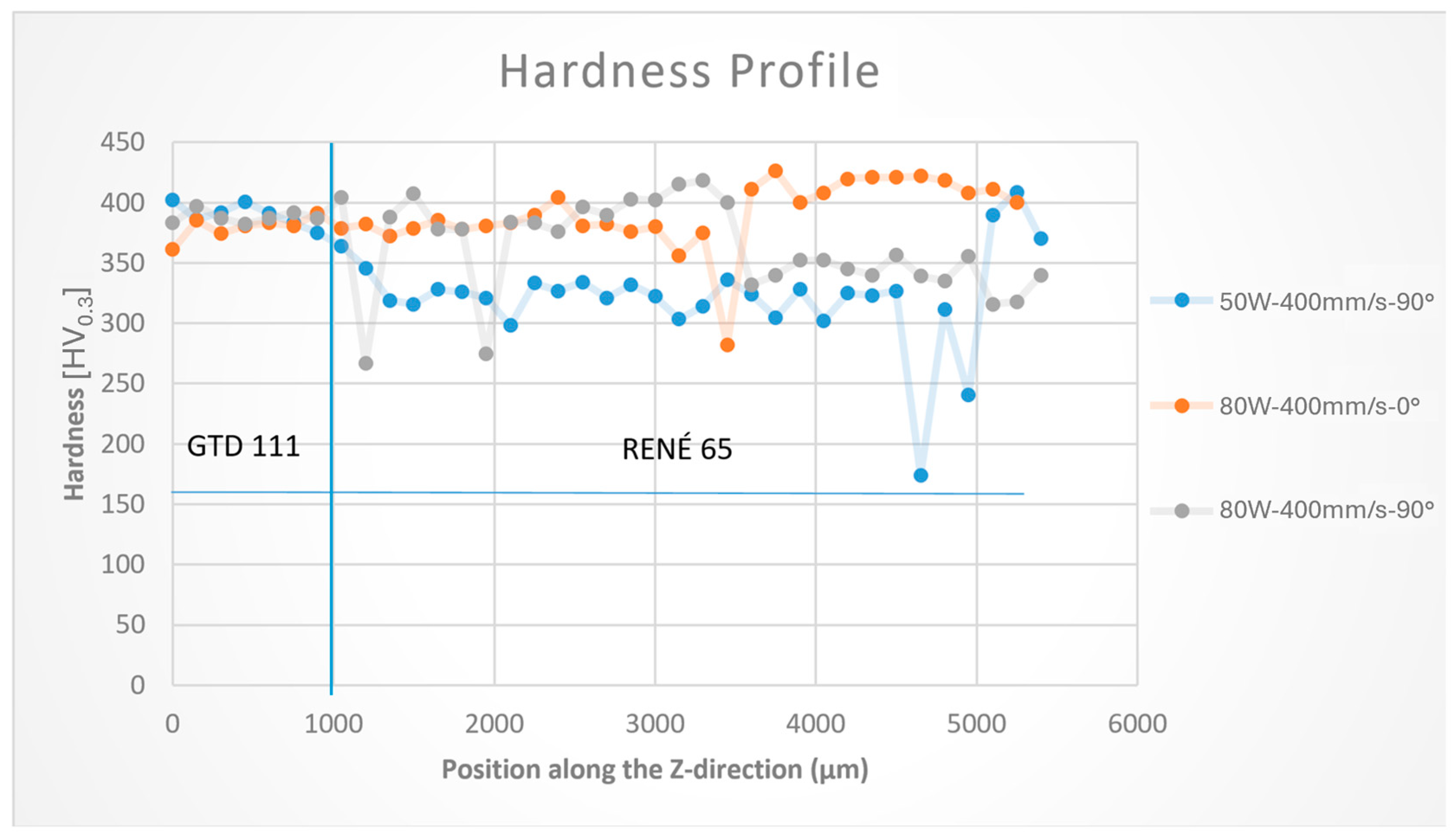
3.3.1. Experimental Stage
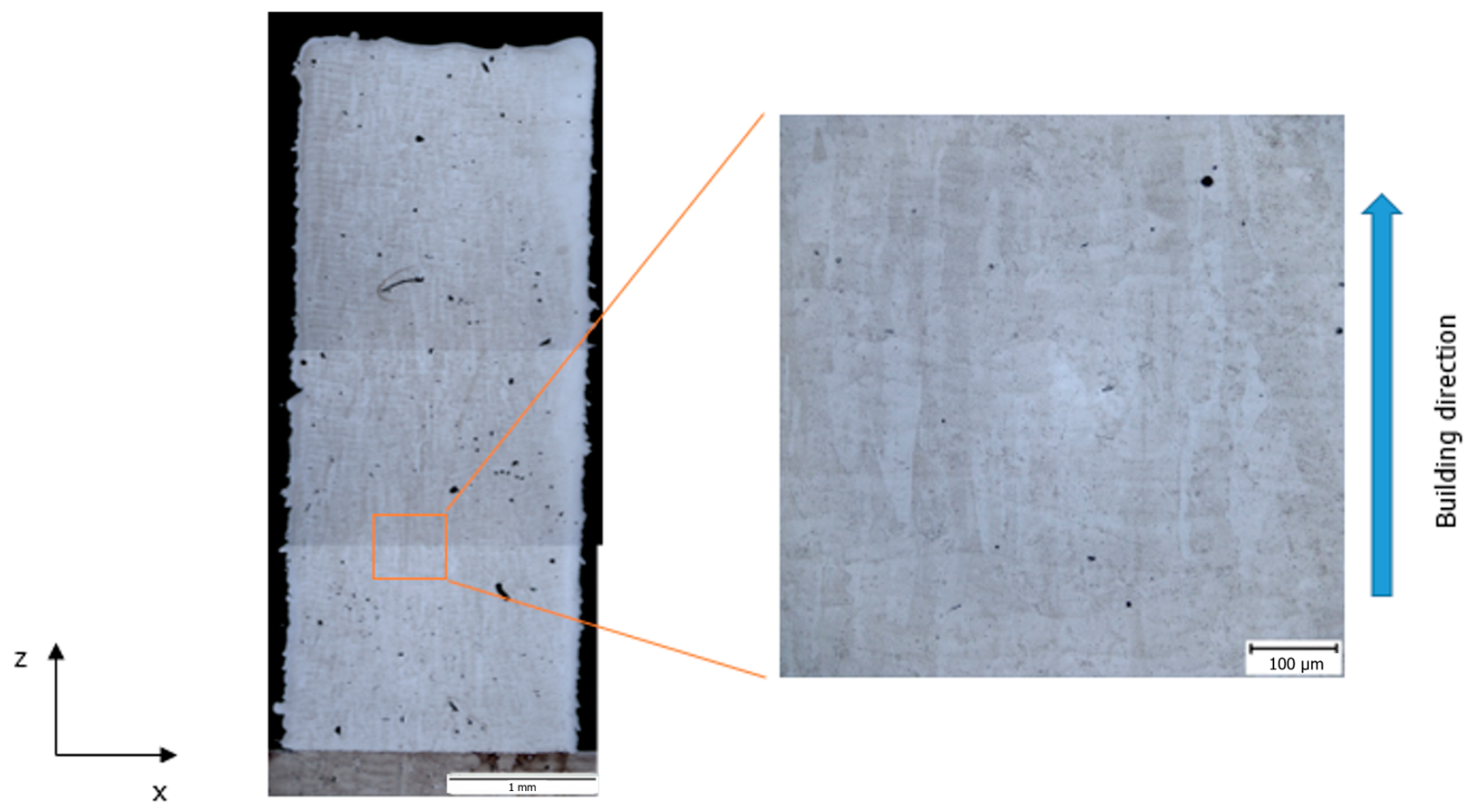
3.3.2. Wall-Tip Repair
4. Conclusions
Author Contributions
Funding
Institutional Review Board Statement
Informed Consent Statement
Data Availability Statement
Acknowledgments
Conflicts of Interest
References
- Li, P.; Yang, T.; Li, S.; Liu, D.; Hu, Q.; Xiong, W.; Zeng, X. Direct laser fabrication of nickel alloy samples. Int. J. Mach. Tools Manuf. 2005, 45, 1288–1294. [Google Scholar] [CrossRef]
- Chen, C.; Wu, H.C.; Chiang, M.F. Laser cladding in repair of IN738 turbine blades. Int. Heat Treat. Surf. Eng. 2008, 2, 140–146. [Google Scholar] [CrossRef]
- Jones, J.B.; McNutt, P.; Tosi, R.; Perry, C.; Wimpenny, D.I. Remanufacture of Turbine Blades by Laser Cladding, Machining, and in-Process Scanning in a Single Machine; The University of Texas at Austin: Austin, TX, USA, 2012. [Google Scholar]
- Yilmaz, O.; Gindy, N.; Gao, J. A repair and overhaul methodology for aeroengine components. Robot. Comput.-Integr. Manuf. 2010, 26, 190–201. [Google Scholar] [CrossRef]
- Pauzi, A.A.; Berahim, N.; Husin, S. Degradation of gas turbine blades for a thermal power plant. MATEC Web Conf. 2016, 54, 03002. [Google Scholar]
- Ünal-Saewe, T.; Gahn, L.; Kittel, J.; Gasser, A.; Scheinbaum, J.H. Process development for tip repair of complex-shaped turbine blades with IN718. Procedia Manuf. 2020, 47, 1050–1057. [Google Scholar] [CrossRef]
- Keshavarz, M.K.; Gontcharov, A.; Lowden, P.; Chan, A.; Kulkarni, D.; Brochu, M. Turbine Blade Tip Repair by Laser Directed Energy Deposition Additive Manufacturing Using a Rene 142–MERL 72 Powder Blend. J. Manuf. Mater. Process. 2021, 5, 21. [Google Scholar] [CrossRef]
- Gandini, E.; Agnesone, F.; Taricco, F.; Arrighi, L. Advances in gas turbine blade repair by laser welding. In Turbo Expo: Power for Land, Sea, and Air; ASME: New York, NY, USA, 1997; Volume 78712, p. V004T12A011. [Google Scholar]
- DebRoy, T.; Wei, H.L.; Zuback, J.S.; Mukherjee, T.; Elmer, J.W.; Milewski, J.O.; Zhang, W. Additive manufacturing of metallic components–process, structure and properties. Prog. Mater. Sci. 2018, 92, 112–224. [Google Scholar]
- Ergene, B. Simulation of the production of Inconel 718 and Ti6Al4V biomedical parts with different relative densities by selective laser melting (SLM) method. J. Fac. Eng. Archit. Gazi Univ. 2022, 37, 469–484. [Google Scholar]
- Patterson, A.E.; Messimer, S.L.; Farrington, P.A. Overhanging features and the SLM/DMLS residual stresses problem: Review and future research need. Technologies 2017, 5, 15. [Google Scholar] [CrossRef]
- Hardy, M.C.; Detrois, M.; McDevitt, E.T.; Argyrakis, C.; Saraf, V.; Jablonski, P.D.; Tin, S. Solving recent challenges for wrought Ni-base superalloys. Metall. Mater. Trans. A 2020, 51, 2626–2650. [Google Scholar] [CrossRef]
- Groh, J.; Gabb, T.; Helmink, R.; Wusatowska-Sarnek, A. Rene 65 billet material for forged turbine components. In Proceedings of the 8th International Symposium on Superalloy 718 and Derivatives, Pittsburgh, PA, USA, 28 September–1 October 2014; John Wiley & Sons: Hoboken, NJ, USA, 2014; p. 107. [Google Scholar]
- Li, L. Repair of directionally solidified superalloy GTD-111 by laser-engineered net shaping. J. Mater. Sci. 2006, 41, 7886–7893. [Google Scholar] [CrossRef]
- Schilke, P.W. Advanced Gas Turbine Materials and Coatings; GE ENERGY: Schenectady, NY, USA, 2004. [Google Scholar]
- Jovanović, M.T.; Mišković, Z.; Lukić, B. Microstructure and stress-rupture life of polycrystal directionally solidified, and single crystal castings of nickel-based IN 939 superalloys. Mater. Charact. 1998, 40, 261–268. [Google Scholar]
- Choi, B.G.; Kim, I.S.; Kim, D.H.; Jo, C.Y. Temperature dependence of MC decomposition behavior in Ni-base superalloy GTD 111. Mater. Sci. Eng. A 2008, 478, 329–335. [Google Scholar]
- Li, X.W.; Wang, L.; Dong, J.S.; Lou, L.H. Effect of solidification condition and carbon content on the morphology of MC carbide in directionally solidified nickel-base superalloys. J. Mater. Sci. Technol. 2014, 30, 1296–1300. [Google Scholar]
- Geranmayeh, A.; Malekan, M.; Forghani, F.; Ghorbani, H. Microstructural and mechanical investigations on the heat treatment rejuvenation of a long-term service-exposed GTD-111 Ni-based superalloy. Mater. Sci. Eng. A 2023, 862, 144381. [Google Scholar]
- Sun, W.R.; Lee, J.H.; Seo, S.M.; Choe, S.J.; Hu, Z.Q. The eutectic characteristic of MC-type carbide precipitation in a DS nickel-base superalloy. Mater. Sci. Eng. A 1999, 271, 143–149. [Google Scholar] [CrossRef]
- Beretta, S.; Romano, S. A comparison of fatigue strength sensitivity to defects for materials manufactured by AM or traditional processes. Int. J. Fatigue 2017, 94, 178–191. [Google Scholar] [CrossRef]
- Deng, D. Additively Manufactured Inconel 718: Microstructures and Mechanical Properties; Linköping University Electronic Press: Linköping, Sweden, 2018; Volume 1798. [Google Scholar]
- León-Henao, H. Technical Feasibility of Recovering Degraded GTD 111 Blades in Service Through Heat Treatment and Additive Manufacturing. Master Thesis, Universidad Nacional de Colombia, Medellin, Colombia, 2022. [Google Scholar]


| Alloy | Ni | C | Al | B | Co | Cr | Fe | Mo | Nb | Ti | W | Zr | Ta |
|---|---|---|---|---|---|---|---|---|---|---|---|---|---|
| Rene 65 | Bal. | --- | 1.8 | 0.01 | 12.3 | 15.6 | 0.8 | 3.2 | 0.7 | 3.5 | 3.7 | 0.03 | --- |
| GTD 111 | Bal. | 0.1 | 3.4 | --- | 10.8 | 14.1 | --- | 1.6 | --- | 5.1 | 4.4 | --- | 3.2 |
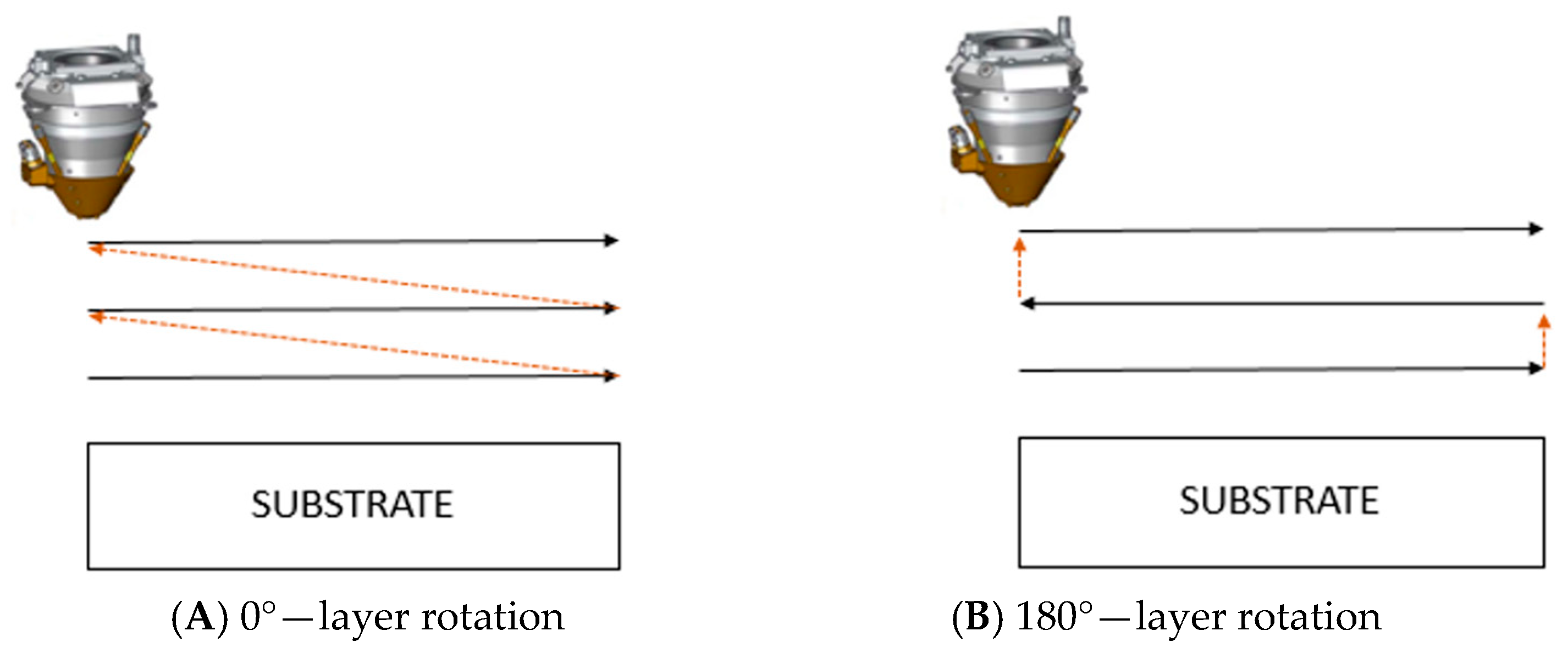
| Power (W) | Scanning Speed (mm/s) | Rotation (°) |
|---|---|---|
| 400 | 7.5, 9.2 | 0, 180 |
| 300 | 7.5, 9.2 | 0, 180 |
| Power (W) | Scanning Speed (mm/s) | Rotation (°) |
|---|---|---|
| 50 | 200, 400 | 0, 90 |
| 80 | 200, 400 | 0, 90 |
Disclaimer/Publisher’s Note: The statements, opinions and data contained in all publications are solely those of the individual author(s) and contributor(s) and not of MDPI and/or the editor(s). MDPI and/or the editor(s) disclaim responsibility for any injury to people or property resulting from any ideas, methods, instructions or products referred to in the content. |
© 2025 by the authors. Licensee MDPI, Basel, Switzerland. This article is an open access article distributed under the terms and conditions of the Creative Commons Attribution (CC BY) license (https://creativecommons.org/licenses/by/4.0/).
Share and Cite
León-Henao, H.; Herderick, E.D.; Toro, A.; Giraldo-Barrada, J.E.; Ramirez, A.J. Assessing the Printability of Rene 65 Powder for Repairing Degraded GTD 111 Gas Turbine Blades Using L-DED and L-PBF. Coatings 2025, 15, 410. https://doi.org/10.3390/coatings15040410
León-Henao H, Herderick ED, Toro A, Giraldo-Barrada JE, Ramirez AJ. Assessing the Printability of Rene 65 Powder for Repairing Degraded GTD 111 Gas Turbine Blades Using L-DED and L-PBF. Coatings. 2025; 15(4):410. https://doi.org/10.3390/coatings15040410
Chicago/Turabian StyleLeón-Henao, Henry, Edward D. Herderick, Alejandro Toro, Jorge E. Giraldo-Barrada, and Antonio J. Ramirez. 2025. "Assessing the Printability of Rene 65 Powder for Repairing Degraded GTD 111 Gas Turbine Blades Using L-DED and L-PBF" Coatings 15, no. 4: 410. https://doi.org/10.3390/coatings15040410
APA StyleLeón-Henao, H., Herderick, E. D., Toro, A., Giraldo-Barrada, J. E., & Ramirez, A. J. (2025). Assessing the Printability of Rene 65 Powder for Repairing Degraded GTD 111 Gas Turbine Blades Using L-DED and L-PBF. Coatings, 15(4), 410. https://doi.org/10.3390/coatings15040410