Article

Effect of Liquid CO2 on Wear Behaviour of TiAlN Hard Coating at Elevated Temperatures

1
Jožef Stefan Institute, Department of Thin Films and Surfaces, Jamova 39, SI-1000 Ljubljana, Slovenia
2
Faculty of Mechanical Engineering, University of Ljubljana, Aškerčeva 6, SI-1000 Ljubljana, Slovenia
*
Author to whom correspondence should be addressed.
Coatings 2025, 15(5), 553; https://doi.org/10.3390/coatings15050553
Submission received: 4 April 2025 / Revised: 30 April 2025 / Accepted: 3 May 2025 / Published: 5 May 2025
(This article belongs to the Section Corrosion, Wear and Erosion)

Abstract

:
PVD hard coatings improve the wear and frictional properties in metal cutting and, therefore, extend the lives of cutting tools. Cutting fluids, including the novel use of liquid carbon dioxide (LCO2), are crucial for reducing tool wear and enhancing machining efficiency. This experimental research is focused on ball-on-disc wear tests of TiAlN hard coatings in environmental, N2 and CO2 atmospheres. In the latter case, the experiments were also performed by adding LCO2 directly into the contact zone. In order to achieve the same temperatures as real cutting conditions, tests were performed at 250 °C, 500 °C and 700 °C, in addition to room temperature. Results show that the TiAlN coating had the highest wear rate in room-temperature tests, regardless of the atmosphere. The wear significantly dropped with the test temperature. It was the lower in the CO2 atmosphere at all temperatures than in all gas-only atmospheres. When LCO2 was introduced to the contact, the wear was at its highest at 500 °C, which is the opposite of all other gas-only atmospheres, where it was at its lowest. In all tribological LCO2 tests, we noticed increased friction coefficient fluctuations. In all gas-only atmospheres, adhered material was observed on the wear tracks, but in LCO2, wear debris was not detected either on the disk or on the ball.

Graphical Abstract

1. Introduction

In metal machining processes, heat is generated in the tool–chip interface zone and transferred to the tool, workpiece and chip. Heat generation depends on several factors, such as machining parameters, properties of the workpiece and tool material, cooling and lubricating effectiveness. The generated heat influences tool wear, the integrity of the workpiece surface and chip formation mechanisms [1,2,3]. Although high cutting temperatures usually soften the workpiece material and, therefore, decrease the cutting forces, they also have a negative effect on the tool material. Chemical reactivity at high temperatures can lead to adhesion and diffusion wear on the tool, resulting in a reduced lifetime of the tool [4,5]. When machining difficult-to-machine materials, the generated heat is mainly transferred to the tool due to the poor thermal conductivity of the workpiece material. Difficult-to-machine materials also better maintain their strength and hardness at elevated temperatures [4,6]. However, research [5] has shown that each material has an optimal cutting temperature where the ratio between cutting forces, tool life and the effect on surface integrity is optimal. Therefore, the goal of machining process optimization is to reach and maintain this optimal temperature throughout the cutting process.
The machining process can be improved by the use of tools protected with hard coatings based on transition metal nitrides with poor thermal conductivity; the use of such protective coatings deflects the heat flow from the tool to the chip [5,7,8]. In dry cutting, the cutting edge of the tool is exposed to high stresses in the cutting zone and high temperatures [9,10]. Hence, a protective coating with high hardness, thermal stability and oxidation resistance is required to improve the tool life. TiAlN-based coatings are widely used for forming and machining applications due to their mechanical properties and thermal stability [11]. At high temperatures, the TiAlN coating forms a thin Al2O3 layer, slowing oxygen diffusion and further protecting the coating from excessive wear. As spinodal decomposition processes occur, the hardness of the coating is further increased, making it more resilient to wear [12,13,14,15].
Another well-established way to enable high cutting speeds and the cutting of modern materials is to use cooling lubrication fluids (CLFs) to decrease the temperature in the cutting area during metal cutting. These fluids have multiple functions. They cool the machining area (the workpiece and the tool), decrease the friction between the workpiece and the tool and help remove chips and fine dust from the machining area. Better cooling can be achieved using liquid nitrogen (LN2) or liquid carbon dioxide (LCO2), without the harmful effects on the environment caused by existing CLFs [16,17].
The utilization of both approaches, i.e., tools covered with a hard protective coating and cooling with LCO2, is relatively new and not sufficiently well understood. Studies conducted so far show that the usage of LCO2 significantly decreases tool wear. Sadik et al. [18] showed that cooling with LCO2 reduces the tendency of thermal cracks to propagate laterally on the surface of TiAlN-coated cutting tools, which delays the chipping of the cutting edge, leading to an extended tool life. A similar increase in tool lifetime was obtained by Klocke et al. [19], who suggested that the reason could be the suppression of oxygen by CO2 gas. Studies by Nimel Sworna Ross [20] and Manimaran [21] showed that tool wear decreases as a result of low temperatures of the LCO2 stream. Tool wear analysis revealed that adhesion and abrasion wear were less intensive in cryogenic cooling compared to other cooling strategies. Similar conclusions were drawn by Halim et al. [22], who confirmed abrasive, adhesive and oxidation wear as the mechanisms causing tool wear.
Several studies have addressed the tribological behaviour of TiAlN at room and elevated temperatures [23,24,25,26,27,28,29,30,31,32] and in various atmospheres, such as nitrogen and oxygen atmospheres [33,34]. But only limited information is available on the tribological behaviour of TiAlN PVD coatings using cryogenic LCO2.
Therefore, the present work separates the influence of CO2 or different inert environments (N2) from the cooling effect of LCO2 and examines the wear and friction properties of TiAlN hard coatings at room and elevated temperatures in these environments.

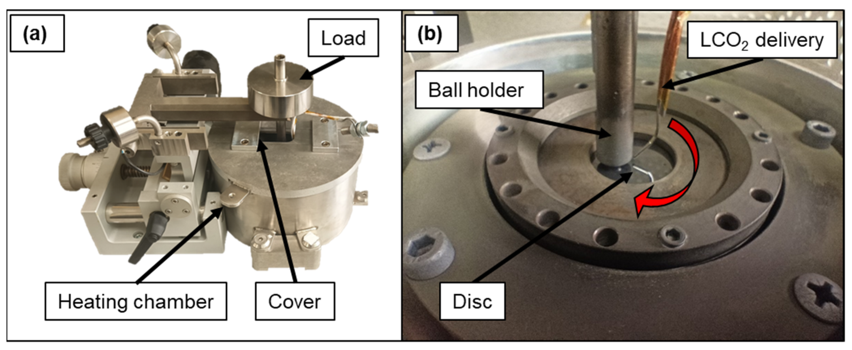
2. Materials and Methods

The deposition of the TiAlN coating was carried out in an industrial Kobelco AIPocket cathodic arc evaporation unit using TiAl (Ti:Al = 40:60; at. %) targets. Disc samples that were used for our studies had a diameter of 30 mm and were made of K10-grade WC-Co (WC 94%, Co 6%; hardness 1840 HV30). They were polished to reach a final roughness of Ra = 10 nm. All samples were cleaned in an ultrasonic bath and sputter-etched before coating deposition. The final coating thickness, as measured using the ball crater technique, was 4.0 µm. The final roughness of the TiAlN-coated samples was Ra = 0.126 µm ± 0.006 µm. A representative cross-section of the as-deposited coating is presented Figure 1a. The coating has a uniform thickness, with no visible structural defects. On the surface, randomly scattered growth defects are visible, which is typical for PVD techniques [35,36]. The XRD diffraction pattern of the TiAlN coating is presented in Figure 1b. Peaks show a face-centred cubic structure with a strong (200) orientation [37,38].
The friction and wear ball-on-disc tests were performed using a standard high-temperature tribometer with a built-in heater and gas inlet (High Temperature Tribometer, Anton Paar), as presented in Figure 2a. The normal load was 5 N, and the linear speed was set to 180 mm/s. The tests were performed at room temperature and elevated temperatures (200 °C, 500 °C and 700 °C) in different atmospheres (ambient air, nitrogen, CO2 and LCO2). The number of cycles was set to 2500 to avoid excessive wear of the coating at a 5 mm radius. As a counter body, a 6 mm tungsten carbide ball was used (ISO Grade K20; Ra < 0.025 µm, diameter variation < 0.25 µm, spherical form < 0.25 µm and hardness 1450 HV30). The maximum Hertzian pressure at the tribological contact was 1.72 GPa. Before tribological testing, the TiAlN-coated samples were cleaned in an ultrasonic bath with ethanol for 5 min, dried, wiped with 2-propanol and purged with dry nitrogen.
During tests under N2 and CO2 atmospheres, a constant flow of pure gas was blown through the tribometer’s inner chamber throughout the whole measurement. The purity of the applied CO2/LCO2 was ≥99.5%, and the purity of N2 was 5.0. Before the test was performed, the gas was fed into the inner chamber continuously for at least 10 min in the case of room temperature and from the start of heating in the case of elevated temperature experiments. LCO2 was added just before the ball-on-disc test began. When performing the tests in an air atmosphere at room temperature, the room conditions were 25 °C and ≈50% relative humidity (RH, measured with a Voltcraft HT-200 humidity meter). For the LCO2 test, the conditions were the same as for the CO2 test, with the addition of LCO2 delivered directly into the contact zone as shown in Figure 2b. We used the liquid phase, delivered through a capillary with a diameter of 0.4 mm at a flow rate of ≈83 g/min. The LCO2 outflow was positioned perpendicular to the direction of rotation with an angle of 45° relative to the disc close to the ball-coating contact (1–2 mm).
For the evaluation of wear tracks, we used confocal optical microscopy (Zeiss Axio CSM 700, Oberkochen, Germany), stylus profilometry (Bruker DektakXT, Billerica, MA, USA) and scanning electron microscopy (SEM, Thermo Fisher Quanta 650 ESEM, Waltham, MA, USA and Helios Nanolab 650, Hillsboro, OR, USA). From each disc, we extracted 100 profiles of wear tracks from a scanned area of 500 µm × 500 µm. Wear volume was calculated based on the measured average wear area and wear-track radius (5 mm). The wear rate was calculated according to the following equation:
K = V / ( F   N ) ,
where V is the wear volume, F is the normal load and N is the number of cycles.
A selected set of tests was repeated several times to demonstrate that the obtained results are reproducible. To measure the nanohardness, we used a Bruker Hysitron, Billerica, MA, USA TS77 nanoindenter.

3. Results

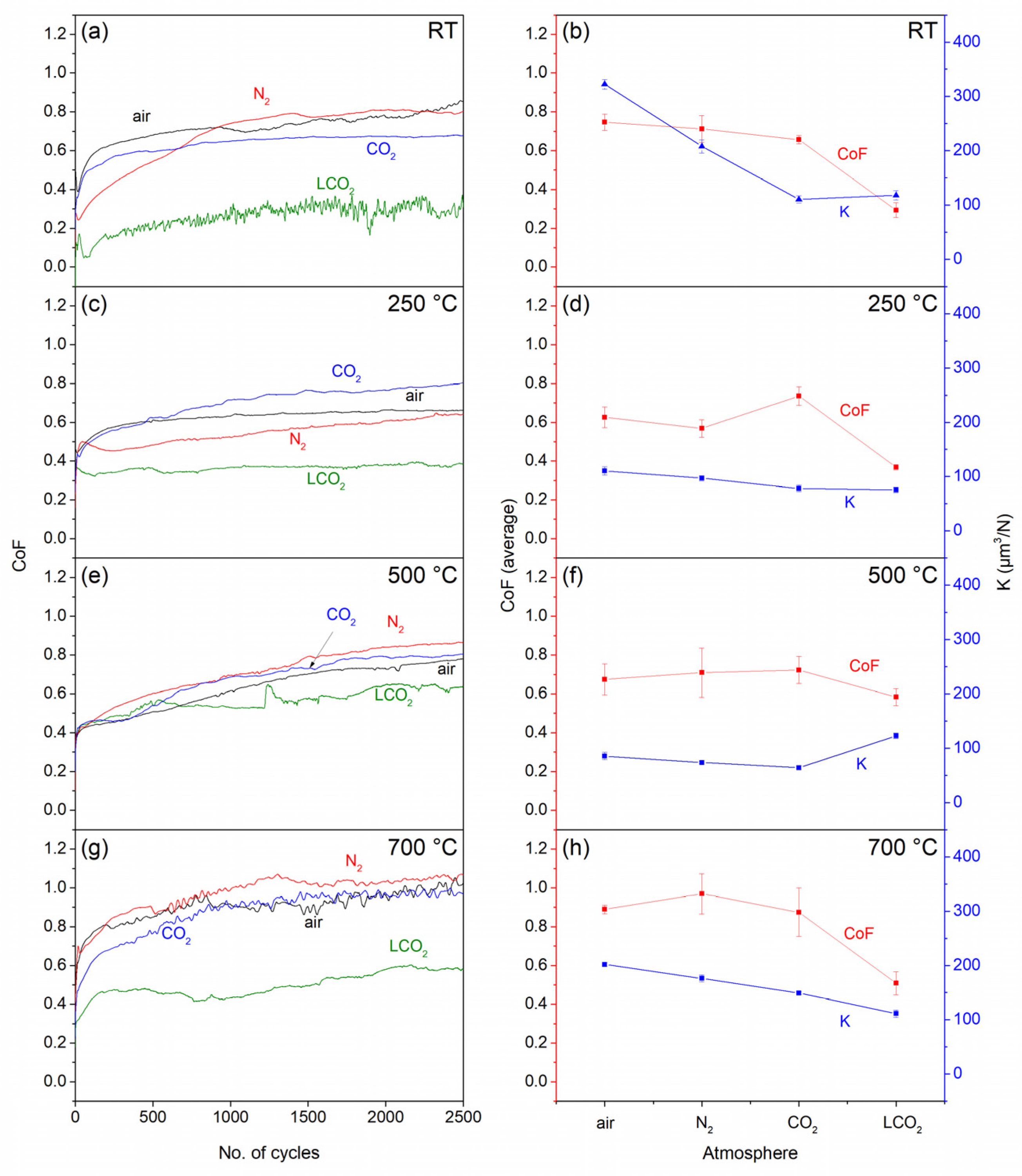
3.1. Friction and Wear Rate

The values of the CoF as a function of the number of cycles at room temperature are presented in Figure 3a. In an ambient air atmosphere, the CoF of the WC-Co ball sliding on a TiAlN-coated disc continuously increases, indicating that the stationary state is not yet been reached. The CoF starts at 0.4 and increases to above 0.8 at the end of the test. At first, he CoF increased due to the increase in the real contact area as the growth defects are broken off and the surfaces are smoothed out. This process generates some heat in the form of flash temperatures, which causes local thin oxide growth. The kinetics of oxidation are different in oxygen-free gas atmospheres, influencing the overall wear. In an N2 atmosphere, the CoF of the WC-Co ball appears similar to that in an air atmosphere, while it reaches a steady-state value of 0.75 at ≈1500 laps. In a CO2 atmosphere, the friction curve is smooth, reaching a steady state after ≈1000 laps at 0.6, which is slightly lower than that of ambient air and N2. Tests performed in a CO2 atmosphere with additional LCO2 delivered into the contact zone are substantially different compared to a pure CO2 atmosphere. The friction curve in LCO2 is not smooth, showing small oscillations, but the CoF does reach a steady-state value after ≈1000 laps at a much lower CoF value of ≈0.3.
From the wear rate coefficient presented in Figure 3b, it can be seen that in the CO2 atmosphere and CO2 atmosphere with LCO2, the wear coefficient is reduced by two-thirds compared to the air atmosphere and by half compared to the N2 atmosphere. The wear depth on the wear track follows a trend similar to that of the wear coefficients, with minor deviations. The wear-track depth is the largest in the case of an air atmosphere (0.95 µm), followed by a nitrogen atmosphere (0.65 µm), while a CO2 atmosphere significantly decreased the depth (0.39 µm). However, when the LCO2 is introduced into the contact zone, the wear depth is similar to that under a CO2 atmosphere, although the CoF is noticeably lower compared to the other atmospheric conditions. Considering a coating thickness of 4.0 µm, the wear depth does not exceed the coating thickness in any case.
Increasing the sample temperature to 250 °C causes changes on the sample surface. Moisture adhered to the surface evaporates, and the sample surface may oxidase, influencing the tribo-chemical reactions promoted by the temperature increase. This results in a different CoF and wear response.
In air (Figure 3c), the average CoF value of 0.6 is reached after ≈500 laps, marking a stationary state. Similarly, in an N2 atmosphere, the CoF steadily increases but does not exceed the value of 0.6. In a CO2 atmosphere, it reaches a steady state after 1500 laps. Different CoF behaviour is observed with additional LCO2 flow into the contact region. The CoF is noticeably the lowest among all atmospheres, without any distinct running-in behaviour at a constant value of ≈0.35.
The wear values at 250 °C (Figure 3d) are similar for all atmospheric conditions. On average, the most significant changes occur in the air and nitrogen environments, with values four and two times lower than at room temperature, respectively. Reductions in wear are also observed in CO2 and LCO2 atmospheres, with changes in the range of 25%.
With a further temperature increase to 500 °C, the CoF behaviour is similar for all atmospheric conditions, as seen in Figure 3e. The lowest friction is obtained when additional cooling is applied with LCO2. The friction curves in the first 500 cycles appear similar, indicating that the surrounding atmosphere has a minimal influence on the initial levelling of the coating surface at this temperature. It is only after this initial stage that the LCO2 conditions stabilize, while in air, N2 and CO2 atmospheres, the friction slowly rises up to 0.8.
Compared to 250 °C, the wear at 500 °C is further decreased for all gas-only atmospheres. The wear is higher by a factor of ≈2 in LCO2 compared to the other atmospheres. An increase is also observed compared to lower temperatures (Figure 3f). While the wear differs between individual atmospheres, the wear-track depths are very close to each other, with similar values at 250 °C and 500 °C.
At the maximum testing temperature of 700 °C, the tribological test shows similar friction for the air, nitrogen and CO2 atmospheres (Figure 3g). After ≈1000 laps, the CoF in all gas-only atmospheres reaches a stationary state, with values ranging from 0.9 up to 1.05 in the nitrogen atmosphere. The lowest friction is detected in LCO2, reaching CoF values between 0.4 and 0.6 after the initial few hundred cycles. Compared to 500 °C, the CoF and wear do not change for LCO2.
The wear rate at 700 °C, as presented in Figure 3h, shows that, similar to other temperatures, the highest wear is in an air atmosphere, with a value of 0.6 µm3/N. Significant reduction in wear, compared to the air atmosphere, is observed in the CO2 and LCO2 atmospheres in the range of 30 to 40%. Wear in the nitrogen atmosphere is ≈15% lower compared to the air atmosphere. Several trends regarding the CoF and wear behaviour in different atmospheres can be observed. In air, one can notice that friction increases as the temperature reaches its peak at 700 °C. Increases in friction with increased temperature have also been measured in some other studies [28,34,37,39], although comparison is not straightforward due to the use of different ball materials and different testing parameters in some cases. These influence the removal of the oxide layer in the wear track that grows faster at increased temperature. In TiAlN, as a high-temperature coating, wear decreases with temperature, reaching a minimum at 500 °C before increasing by more than twice at 700 °C. The reason for this behaviour may be the degradation of mechanical properties above the deposition temperature, where the coating loses a part of its hardness due to pore growth around structural defects and stress relaxation [35]. In the literature, higher a CoF and increased wear air are described as the result of the formation of Al2O3 and TiO2 [11,28,29,37,38], which are formed due to the exposure of the coating to an oxidative environment and (frictional) heat. The upper layer oxidizes and is subsequently removed by a counter body when it reaches a certain critical thickness. Therefore, wear is determined by the rate of oxygen diffusion and the subsequent removal of the oxide layer by the counter body. The breaking of the oxide layer causes an increase in the coefficient of friction due to the particles that are formed in the process [40].
In an inert atmosphere, there is no formation of new oxides on the surface due to the absence of oxygen. However, in our case, although we used inert atmospheres, there was still the possibility of traces of oxygen being present. This may be due the limited design of the tribometer chamber, as oxygen can still enter the chamber through the narrow gap between the top cover and the ball holder. In the nitrogen atmosphere, the wear at room and elevated temperatures is about 35% and 13% lower, respectively, compared to that in the air atmosphere. A trend of lower wear in a nitrogen atmosphere compared to ambient air was also observed by Drnovšek et al. [34] and Terek et al. [24], with the lowest wear values reported at 500 °C. Wear in CO2 is generally ≈25% lower than in an air atmosphere, with the exception of room temperature, where it is 65% lower. The trend of temperature dependence of wear in CO2 is the same as in air or nitrogen, but at a temperature of 700 °C, it exceeds the room-temperature values. While friction and wear behaviour differ between atmospheres, oxidative wear is still the main wear mechanism. In this sense, a CO2 atmosphere provides a purer atmosphere at the contact region, as CO2 is heavier than air and, therefore, fills the entire volume of the testing chamber. At 700 °C, there is a larger oscillation of CoF curves in all three gas-only atmospheres. Similar observations have been confirmed by other authors [24,34,35,41,42], corresponding to an increased amount of oxides, which indicates a change in the wear mechanism at elevated temperatures [42,43].
A significant decrease in the CoF is observed when, in addition to CO2, liquid-phase LCO2 is introduced into the contact zone. This provides effective cooling of the contact region, as well as a protective atmosphere. In contrast to the results obtained by Courbon et al. [44], who observed that LCO2 did not affect the CoF compared to an ambient air atmosphere and, therefore, concluded that it had no lubricating effect, our measurements show a consistently lower friction behaviour in the whole temperature region. Several differences between the measurement setups could have resulted in different frictional behaviours. In our case, prolonged exposure to the LCO2 caused the sample surface to cool down more. This can lead to decelerated evaporation of CO2 flakes from the surface, which may create a thin lubricating layer, confirming the friction-reducing effect of LCO2. We also noticed increased CoF fluctuations at room temperature in the LCO2 atmosphere. The mechanism of the delivery of the liquid phase to the contact may cause additional vibrations. The LCO2 is transferred from the gas cylinder through a capillary tube. Although the flow rate of the LCO2 is set to constant, during the expansion at the nozzle, the LCO2 turns into dry ice, which forms flakes of different sizes [45]. Large fluctuations of the CoF curve can be explained by forces that are caused by uneven distribution or amounts of these flakes coming out of the nozzle. At elevated temperatures, this effect is reduced but not completely eliminated. As mentioned, the CoF in the LCO2 atmosphere is low compared to other atmospheres, with a highest value at 500 °C.
When interpreting the results of tests using LCO2, we must consider the error in measuring the actual contact temperature. In the tribometer, the temperature is measured below the sample, relatively far from the coated sample surface. The actual temperature on the surface is lower than that of the bulk. When LCO2 is added, the surface is further cooled [46,47], and thus, significantly lower temperatures are achieved at the ball–disc contact. Despite the active operation of a heater in the tribometer, the temperature of the thermocouple drops to ≈410 °C at 500 °C and to ≈480 °C at 700 °C; therefore, we can assume that the actual temperature at the contact is significantly lower. This could explain the decrease in the CoF from 500 °C to 700 °C. In all other atmospheres, the CoF reaches its minimum at 500 °C; in LCO2, a similar contact temperature occurs at a much higher set temperature due to the effective cooling of LCO2.
Wear of the TiAlN coating in all decreases from room temperature to 500 °C in all atmospheres, where it reaches a minimum; then, at 700 °C, it increases again, reaching higher values than at 250 °C. The greatest drop in wear at 500 °C occurs in an ambient air atmosphere, where the wear coefficient drops by a factor of ≈3.7, and in N2, where it drops by a factor ≈ 2.8 compared to room temperature. In a CO2 atmosphere, the drop is not as steep but constant.
However, when LCO2 is used, the results at elevated temperatures are completely reversed. At 500 °C, the wear is the most intense, while at 250 °C, it is the least intense, which aligns with the CoF trend. At 700 °C, the wear rate, again, slightly drops compared to the values at 500 °C, and the maximum wear-track depth noticeably drops, reaching the lowest values under all testing conditions (0.17 µm), suggesting that counter-body wear increases the width of the wear track on the coating. Therefore, to better understand of coating wear, it is also important to consider the wear behaviour of the counter body. The wear coefficient (K) as a function of temperature is shown in Figure 4. It is obvious that K does not noticeably change up to a temperature of 500 °C, regardless of the atmosphere. At 700 °C, it increases by a factor of ≈10 in ambient air and by a factor of ≈3 in N2 and CO2 atmospheres. This is consistent with findings [28,48,49] that WC-Co hardness decreases at elevated temperatures. In the case of LCO2, K does not change as the temperature rises, which confirms the effectiveness of the cooling effect of LCO2.

3.2. Analysis of Wear Tracks

SEM and EDS analyses were performed in several areas across the wear track on discs after the ball-on-disc tests. Figure 5 presents SEM top-view images of the wear track after tests at room temperature. The coating surface has plenty of micro-droplets, which result from the use of the cathodic arc deposition process [36]. Th EDS analysis presented in Table 1 shows the composition of the coating, wear track and wear debris on the surface. At room temperature, in all atmospheres, a large amount of adhered material is present at the sides and in the middle of the wear track; however, in the case of LCO2 delivered in the contact zone, the wear track has no visibly adhered material. The composition of the material in the wear track in the case of air and nitrogen atmospheres is similar to the undisturbed coating, while in the case of the CO2 atmosphere, it contains a significant amount of oxygen. These results suggest that CO2 molecules can react with the coating surface or debris under high pressure [50].
From analysis of adhered material on the wear tracks, it can be concluded that oxidation of the transferred counter-body material is less probable, as there no tungsten oxides are observed. In the case of ambient air, N2 and CO2 atmospheres, wear debris contains oxygen, which proves the presence of oxidized elements of the coating. This could be attributed to the formation of an Al2O3–TiO2 oxide layer on top of the coatings [51]. Therefore, the content of oxides in the wear debris in all atmospheres is most likely due to low wear, with the top layer of the coating wearing out. Since this layer contains oxides, this is also noticeable in the composition of wear debris that is deposited along the wear track. Visible deep grooves in the middle and along the edge of the wear tracks (Figure 5a,b) indicate the presence of abrasive wear, while plastic deformation of the edge and loose particles (Figure 5a–c) indicate an adhesive wear mechanism. The absence of adhered material in the case of LCO2 can be attributed to the flow of LCO2, which removes material from the contact zone and prevents the sticking of material on the disc surface. Oxygen is not detected in the case of LCO2, either in the undisturbed coating nor on the worn surface, indicating the effectiveness of the protective atmosphere against oxidation at room temperature. Considering the absence of oxides, the reduction in wear is unlikely due to the formation of Al2O3, but it can be attributed to other factors.
In the CO2 atmosphere, we observe fish scale-like debris, as shown in inset in Figure 5c. Similar behaviour was reported by Drnovšek et al. [34], who observed such a pattern in an oxygen atmosphere. Debris in the form of fish scales is formed by oxides; however, the surrounding wear track contains no oxygen. In our study, we found the presence of oxides throughout the wear track, with the proportion of oxygen being higher in the area where there is fish scale-like debris. This indicates that the CO2 atmosphere has a significant influence on the shape and formation of debris. Similar debris is also observed at 700 °C in a CO2 atmosphere.
In an air atmosphere, we also observe roll-like debris, which is typical for TiAlN coatings [39,52,53,54], accumulated on both edges of the wear track—only at 250 °C. Debris with a length of 2–6 µm is aligned mostly perpendicularly to the sliding direction. Zhou et al. [55] and Drnovšek et al. [34] reported roll-like debris, mainly in nitrogen atmospheres in low-temperature tribological tests with low wear rate. The mechanism of formation of this debris is not entirely clear; however, Zhou et al. [53] suggested that there is a strong connection between the absorbed water content in the coating and the formation of debris. This finding could confirm our observations of the formation of roll-like debris structures only in an air atmosphere, since under all other conditions, there is less moisture present, especially at elevated temperatures. The EDS spectrum of roll-like debris presented in Figure 6 shows the presence of oxygen and confirms the presence of the ball material.
The wear-track analysis presented in Figure 7 shows that, compared to a pure CO2 atmosphere at elevated temperatures, the LCO2 atmosphere does not significantly differ, either in terms of the visual appearance of the wear track or in terms of its composition. There is no visible wear debris under any temperature condition (Figure 7c,d). At higher magnifications (inset of Figure 7d), smearing of the coating in the wear track is visible, with no groves present. This suggests the very limited presence or absence of an abrasive wear mechanism. However, there is a significant difference in the proportion of oxygen, which, at all elevated temperatures, is ≈3 at. % in the undisturbed coating and ≈10 at. % in the wear track. Clear differences in the topography and composition of the wear tracks at individual temperatures are observed in the CO2 atmosphere, similar to the ambient LCO2 atmosphere, but there is no cooling effect, and no wear parts are removed due to the flow of LCO2. The EDS analysis presented in Table 2 shows the composition of the coating, wear track and wear debris on the surface in tests performed at room and elevated temperatures. At room temperature, a large amount of adhered material is present at the sides and in the middle of the wear track; however, the amount of debris is noticeably lower at 250 °C and 500 °C, which is also consistent with the lower wear rate at these temperatures. At room temperature, 250 °C and 500 °C, the oxygen content in the unworn part of the coating is similar, while at 700 °C the oxygen content is higher by a factor of two. At this temperature, the wear debris also contains the highest proportion of oxygen. In all three cases of tests at elevated temperatures, traces of the ball material are detected in the wear debris. The highest proportion is detected at 700 °C, which is consistent with the observed ball wear trend. In the inset of Figure 7b, groves and adhered material are clearly visible in the middle of the wear track, confirming both the abrasive and adhesive wear mechanisms. The proportion of oxygen in the LCO2 atmosphere in the undisturbed coating confirms the non-reactivity of the coating with CO2. In the wear track, where the pressure is increased due to mechanical contact, oxidation of the coating or wear debris occurs, which may be a consequence of the reactivity of CO2 at increased pressure [50].
The nanohardness of the undisturbed TiAlN coating after the ball-on-disc experiments at room temperature and elevated temperatures in different atmospheres is presented in Figure 8. In the hardness analysis, it is necessary to consider the large scatter of values, which is the result of the ratio between the indentation depth and surface roughness. Despite the large scatter of values, it can be seen that the lines follow a consistent trend. The hardness of the undisturbed coating is similar in all inert atmospheres, with a room-temperature value of 33 GPa. Although the hardness in ambient air at room temperature is higher than in other atmospheres, at all elevated temperatures, it is ≈5 GPa lower compared to inert atmospheres, which is a consequence of oxidation.

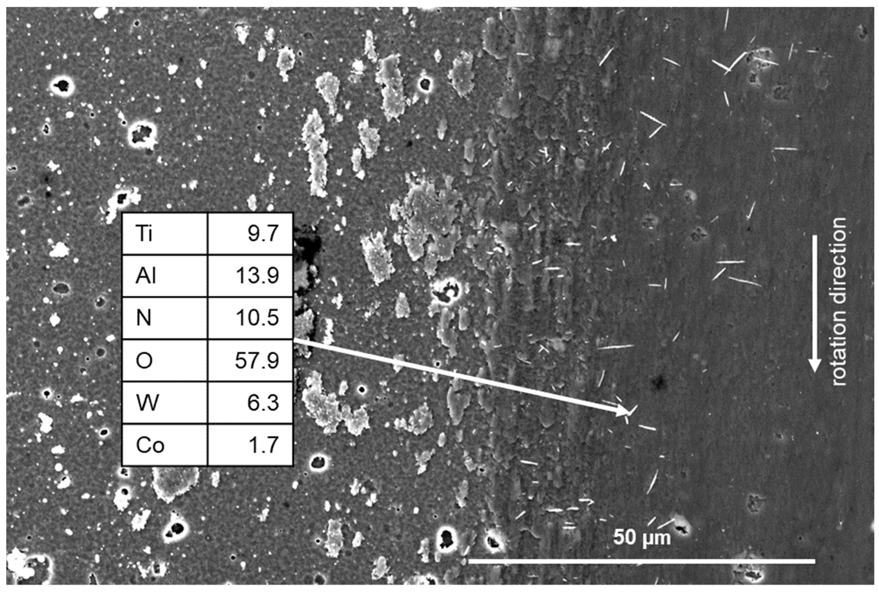
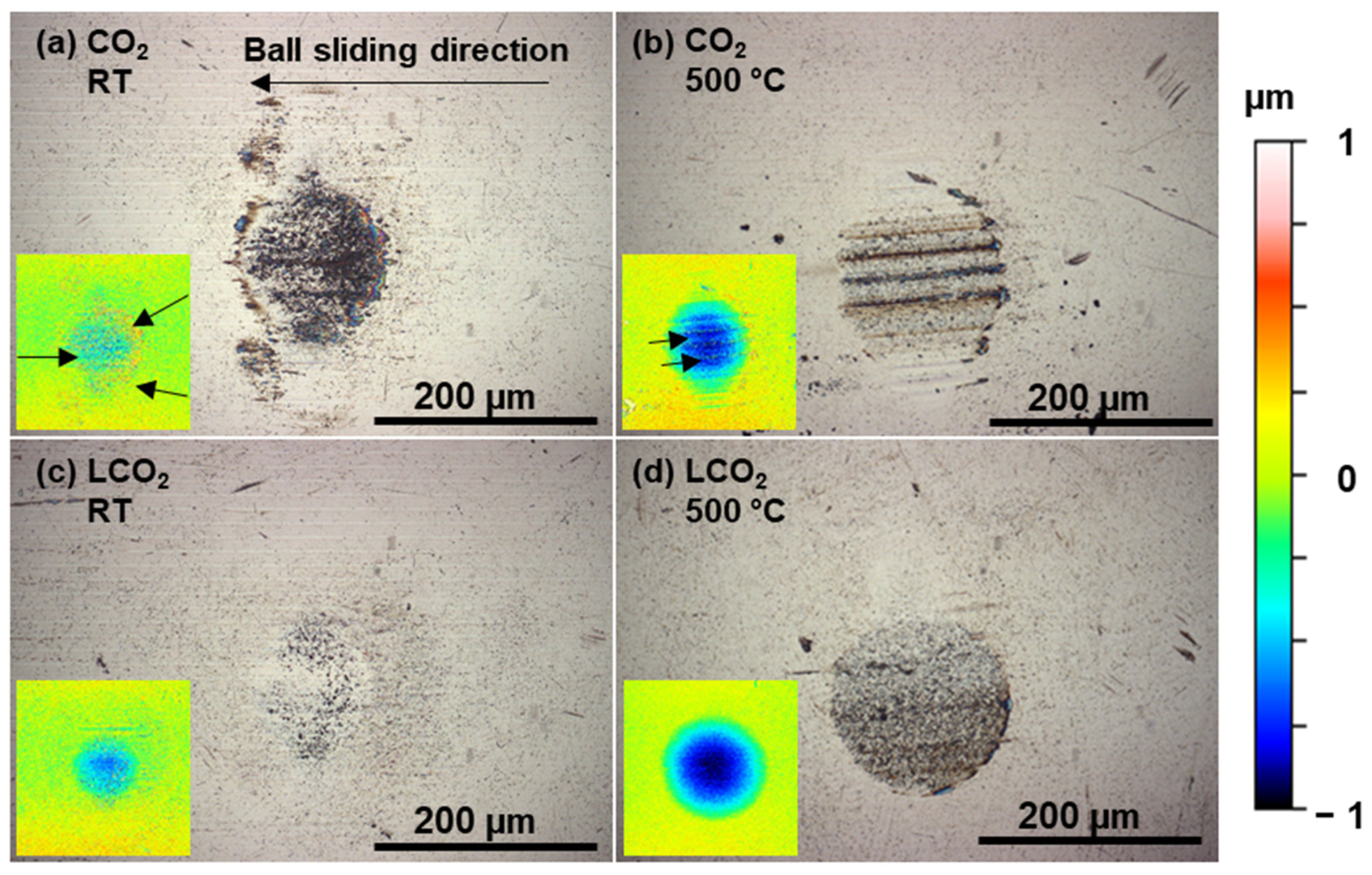
3.3. Counter-Body Analysis

In all gas-only atmospheres, the material adheres to the worn area. On the inserts showing levelled 3D profilometry scans (Figure 9a,b), visibly adhered material on the surface of the ball used in the CO2 atmosphere is marked with arrows. When additional LCO2 was added to the contact zone in a CO2 atmosphere, the wear mechanisms changed significantly. The surface roughness of the wear track on the disc is noticeably lower, and there is no visible debris on the worn surface either. Analysis of the ball surface (Figure 9c,d) shows that the diameters of the worn area are slightly smaller compared to CO2, the surface has a lower roughness and the adhered material is not visible.
This observation supports the conclusion that LCO2 flow prevents the material from sticking to the surface of both the ball and the disc. This also explains the observed lower wear of TiAlN, since LCO2 flow removes abrasive particles from the contact zone and the surrounding area, reducing adhesive and abrasive wear.
Furthermore, research [56,57] has shown that cooling a TiAlN coating to cryogenic temperatures improves its mechanical properties, such as by increasing its hardness and significantly increasing its wear resistance. Temperatures in the contact zone could drop to the boiling point of LCO2, which is −78.5 °C under ambient pressure. The contact and the surroundings cool down due to the influence of latent heat, which is the result of the expansion of LCO2 and the associated phase transformation [57]. Despite the rapid change in temperature, we did not observe any cracks on the surface of the coating or on the wear track using SEM analysis.

4. Conclusions

In this work, the tribological behaviour of a TiAlN hard coating was evaluated in different atmospheres at room and high temperatures. The impact of LCO2, used as a cooling fluid, was given special attention. The following conclusions can be drawn from the presented results:
-
The coefficient of friction (CoF) in CO2 was similar to that in air and N2 atmospheres. In LCO2 the CoF consistently resulted in the lowest values at all temperatures. The decrease in the CoF in LCO2 can be attributed to the lower temperature in the contact zone and the presence of a thin lubricating layer, confirming the friction-reducing effect of LCO2.
-
In LCO2, we noticed increased CoF fluctuations caused by uneven distribution or amounts of dry ice flakes coming out of the nozzle during the expansion of the LCO2. At elevated temperatures, this effect is reduced but not completely eliminated.
-
The wear rate was the lower in the CO2 atmosphere at all temperatures compared to all gas-only atmospheres. In LCO2, the wear rate was similar to that under CO2 at room temperature and 250 °C and lower at 700 °C, but at 500 °C, it was the highest among all atmospheres.
-
The counter-body wear rate was similar at all temperatures up to 500 °C, independent of atmosphere. At 700 °C, it increased in all gas-only atmospheres, but under LCO2, there were no significant changes. This confirms the cooling effect of LCO2.
In all gas-only atmospheres, adhered material was observed on the wear tracks, but in LCO2, wear debris was not detected, either on the disk or on the ball. This finding confirms that LCO2 flow prevents the material from sticking to the surface of both the ball and the disc. Furthermore, LCO2 flow removes abrasive particles from the contact zone and the surrounding area.

Author Contributions

Conceptualization, M.D., F.P. and M.Č.; Methodology, M.D. and M.Č.; Validation, M.D., A.D., F.P. and M.Č.; Formal analysis, M.D. and A.D.; Investigation, M.D. and A.D.; Resources, M.Č.; Writing—original draft, M.D.; Writing—review & editing, A.D., F.P. and M.Č.; Visualization, M.D.; Supervision, F.P. and M.Č.; Project administration, M.Č.; Funding acquisition, M.Č. All authors have read and agreed to the published version of the manuscript.

Funding

This research was financially supported by the Slovenian Research and Innovation Agency (ARIS) within the framework of the Young Researcher program and research core funding program P2-0082.

Data Availability Statement

The data presented in this study are available upon request from the corresponding author.

Conflicts of Interest

The authors declare no conflicts of interest.

References

  1. Kitagawa, T.; Kubo, A.; Maekawa, K. Temperature and wear of cutting tools in high-speed machining of Inconel 718 and Ti6Al6V2Sn. Wear 1997, 202, 142–148. [Google Scholar] [CrossRef]
  2. Dewes, R.C.; Ng, E.; Chua, K.S.; Newton, P.G.; Aspinwall, D.K. Temperature measurement when high speed machining hardened mould/die steel. J. Mater. Process. Technol. 1999, 92–93, 293–301. [Google Scholar] [CrossRef]
  3. Ogedengbe, T.; Okediji, A.P.; Yussouf, A.A.; Aderoba, O.A.; Alabi, I.O.; Alonge, O.I. The Effects of Heat Generation on Cutting Tool and Machined Workpiece. J. Phys. Conf. Ser. 2019, 1378, 022012. [Google Scholar] [CrossRef]
  4. Shokrani, A.; Dhokia, V.; Newman, S. Environmentally conscious machining of difficult-to-machine materials with regard to cutting fluids. Int. J. Mach. Tools Manuf. 2012, 57, 83–101. [Google Scholar] [CrossRef]
  5. Abukhshim, N.A.; Mativenga, P.T.; Sheikh, M.A. Heat generation and temperature prediction in metal cutting: A review and implications for high speed machining. Int. J. Mach. Tools Manuf. 2006, 46, 782–800. [Google Scholar] [CrossRef]
  6. Wegener, K.; Kuster, F.; Weikert, S.; Weiss, L.; Stirnimann, J. Success Story Cutting. Procedia CIRP 2016, 46, 512–524. [Google Scholar] [CrossRef]
  7. Kryzhanivskyy, V.; M’saoubi, R.; Ståhl, J.-E.; Bushlya, V. Tool–chip thermal conductance coefficient and heat flux in machining: Theory, model and experiment. Int. J. Mach. Tools Manuf. 2019, 147, 103468. [Google Scholar] [CrossRef]
  8. Schalk, N.; Tkadletz, M.; Mitterer, C. Hard coatings for cutting applications: Physical vs. chemical vapor deposition and future challenges for the coatings community. Surf. Coat. Technol. 2022, 429, 127949. [Google Scholar] [CrossRef]
  9. Ning, Y.; Rahman, M.; Wong, Y. Investigation of chip formation in high speed end milling. J. Mech. Work. Technol. 2001, 113, 360–367. [Google Scholar] [CrossRef]
  10. Weinert, K.; Inasaki, I.; Sutherland, J.; Wakabayashi, T. Dry Machining and Minimum Quantity Lubrication. CIRP Ann. 2004, 53, 511–537. [Google Scholar] [CrossRef]
  11. Koller, C.; Hollerweger, R.; Sabitzer, C.; Rachbauer, R.; Kolozsvári, S.; Paulitsch, J.; Mayrhofer, P. Thermal stability and oxidation resistance of arc evaporated TiAlN, TaAlN, TiAlTaN, and TiAlN/TaAlN coatings. Surf. Coat. Technol. 2014, 259, 599–607. [Google Scholar] [CrossRef]
  12. Bartosik, M.; Rumeau, C.; Hahn, R.; Zhang, Z.L.; Mayrhofer, P.H. Fracture toughness and structural evolution in the TiAlN system upon annealing. Sci. Rep. 2017, 7, 16476. [Google Scholar] [CrossRef]
  13. Grzesik, W.; Małecka, J.; Kwaśny, W. Identification of oxidation process of TiALN coatings versus heat resistant aerospace alloys based on diffusion couples and tool wear tests. CIRP Ann. 2020, 69, 41–44. [Google Scholar] [CrossRef]
  14. Gao, C.; Yan, J.; Dong, L.; Li, D. Influence of Al2O3 layer thickness on high-temperature stability of TiAlN/Al2O3 multilayers. Appl. Surf. Sci. 2013, 285, 287–292. [Google Scholar] [CrossRef]
  15. Chim, Y.C.; Ding, X.Z.; Zeng, X.T.; Zhang, S. Oxidation resistance of TiN, CrN, TiAlN and CrAlN coatings deposited by lateral rotating cathode arc. Thin Solid Films 2009, 517, 4845–4849. [Google Scholar] [CrossRef]
  16. Benedicto, E.; Carou, D.; Rubio, E. Technical, Economic and Environmental Review of the Lubrication/Cooling Systems Used in Machining Processes. Procedia Eng. 2017, 184, 99–116. [Google Scholar] [CrossRef]
  17. Proud, L.; Tapoglou, N.; Slatter, T. A Review of CO2 Coolants for Sustainable Machining. Metals 2022, 12, 283. [Google Scholar] [CrossRef]
  18. Sadik, M.I.; Isakson, S.; Malakizadi, A.; Nyborg, L. Influence of Coolant Flow Rate on Tool Life and Wear Development in Cryogenic and Wet Milling of Ti-6Al-4V. Procedia CIRP 2016, 46, 91–94. [Google Scholar] [CrossRef]
  19. Klocke, F.; Lung, D.; Krämer, A.; Cayli, T.; Sangermann, H. Potential of Modern Lubricoolant Strategies on Cutting Performance. Key Eng. Mater. 2013, 554–557, 2062–2071. [Google Scholar] [CrossRef]
  20. Ross, K.N.S.; Manimaran, G. Effect of cryogenic coolant on machinability of difficult-to-machine Ni–Cr alloy using PVD-TiAlN coated WC tool. J. Braz. Soc. Mech. Sci. Eng. 2019, 41, 44. [Google Scholar] [CrossRef]
  21. Ross, K.N.S.; Manimaran, G. Machining Investigation of Nimonic-80A Superalloy Under Cryogenic CO2 as Coolant Using PVD-TiAlN/TiN Coated Tool at 45° Nozzle Angle. Arab. J. Sci. Eng. 2020, 45, 9267–9281. [Google Scholar] [CrossRef]
  22. Halim, N.H.A.; Haron, C.H.C.; Ghani, J.A.; Azhar, M.F. Tool wear and chip morphology in high-speed milling of hardened Inconel 718 under dry and cryogenic CO2 conditions. Wear 2019, 426–427, 1683–1690. [Google Scholar] [CrossRef]
  23. Geng, Z.; Shi, G.; Shao, T.; Liu, Y.; Duan, D.; Reddyhoff, T. Tribological behavior of patterned TiAlN coatings at elevated temperatures. Surf. Coat. Technol. 2019, 364, 99–114. [Google Scholar] [CrossRef]
  24. Terek, V.; Kovačević, L.; Drnovšek, A.; Panjan, P.; Škorić, B.; Kovač, J.; Bobić, Z.; Terek, P. High-temperature tribological behavior of nanolayered TiAlN/TiSiN coating deposited on WC-Co cemented carbide. Surf. Coat. Technol. 2024, 477, 130316. [Google Scholar] [CrossRef]
  25. Pflüger, E.; Schröer, A.; Voumard, P.; Donohue, L.; Münz, W.-D. Influence of incorporation of Cr and Y on the wear performance of TiAlN coatings at elevated temperatures. Surf. Coat. Technol. 1999, 115, 17–23. [Google Scholar] [CrossRef]
  26. Qi, Z.B.; Sun, P.; Zhu, F.P.; Wu, Z.T.; Liu, B.; Wang, Z.C.; Peng, D.L.; Wu, C.H. Relationship between tribological properties and oxidation behavior of Ti0.34Al0.66N coatings at elevated temperature up to 900 °C. Surf. Coat. Technol. 2013, 231, 267–272. [Google Scholar] [CrossRef]
  27. Staia, M.H.; D’alessandria, M.; Quinto, D.T.; Roudet, F.; Astort, M.M. High-temperature tribological characterization of commercial TiAlN coatings. J. Phys. Condens. Matter 2006, 18, S1727–S1736. [Google Scholar] [CrossRef] [PubMed]
  28. Rodríguez-Baracaldo, R.; Benito, J.; Puchi-Cabrera, E.; Staia, M. High temperature wear resistance of (TiAl)N PVD coating on untreated and gas nitrided AISI H13 steel with different heat treatments. Wear 2007, 262, 380–389. [Google Scholar] [CrossRef]
  29. Jianxin, D.; Aihua, L. Dry sliding wear behavior of PVD TiN, Ti55Al45N, and Ti35Al65N coatings at temperatures up to 600 °C. Int. J. Refract. Met. Hard Mater. 2013, 41, 241–249. [Google Scholar] [CrossRef]
  30. Dejun, K.; Haoyuan, G.; Wenchang, W. Effects of Loadings on Friction and Wear Behaviors of Cathodic Arc Ion Plating AlTiN Coating at High Temperature. Tribol. Trans. 2016, 59, 604–612. [Google Scholar] [CrossRef]
  31. Liu, A.H.; Deng, J.X. Elevated temperature tribological properties of AlTiN coating up to 700 °C. Surf. Eng. 2015, 31, 17–23. [Google Scholar] [CrossRef]
  32. Courbon, C.; Fallqvist, M.; Hardell, J.; M’Saoubi, R.; Prakash, B. Adhesion tendency of PVD TiAlN coatings at elevated temperatures during reciprocating sliding against carbon steel. Wear 2015, 330–331, 209–222. [Google Scholar] [CrossRef]
  33. Gant, A.; Gee, M.; Orkney, L. The wear and friction behaviour of engineering coatings in ambient air and dry nitrogen. Wear 2011, 271, 2164–2175. [Google Scholar] [CrossRef]
  34. Drnovšek, A.; Panjan, P.; Panjan, M.; Paskvale, S.; Buh, J.; Čekada, M. The influence of surrounding atmosphere on tribological properties of hard protective coatings. Surf. Coat. Technol. 2015, 267, 15–20. [Google Scholar] [CrossRef]
  35. Panjan, P.; Drnovšek, A.; Dražić, G. Influence of Growth Defects on the Oxidation Resistance of Sputter-Deposited TiAlN Hard Coatings. Coatings 2021, 11, 123. [Google Scholar] [CrossRef]
  36. Panjan, P.; Drnovšek, A.; Gselman, P.; Čekada, M.; Panjan, M. Review of Growth Defects in Thin Films Prepared by PVD Techniques. Coatings 2020, 10, 447. [Google Scholar] [CrossRef]
  37. Ohnuma, H.; Nihira, N.; Mitsuo, A.; Toyoda, K.; Kubota, K.; Aizawa, T. Effect of aluminum concentration on friction and wear properties of titanium aluminum nitride films. Surf. Coat. Technol. 2004, 177–178, 623–626. [Google Scholar] [CrossRef]
  38. Ikeda, T.; Satoh, H. Phase formation and characterization of hard coatings in the Ti–Al–N system prepared by the cathodic arc ion plating method. Thin Solid Films 1991, 195, 99–110. [Google Scholar] [CrossRef]
  39. Luo, Q. Temperature dependent friction and wear of magnetron sputtered coating TiAlN/VN. Wear 2011, 271, 2058–2066. [Google Scholar] [CrossRef]
  40. Geng, Y.; Tan, H.; Cheng, J.; Chen, J.; Sun, Q.; Zhu, S.; Yang, J. Microstructure, mechanical and vacuum high temperature tribological properties of AlCoCrFeNi high entropy alloy based solid-lubricating composites. Tribol. Int. 2020, 151, 106444. [Google Scholar] [CrossRef]
  41. Ma, H.; Miao, Q.; Liang, W.; Sun, S.; Qi, Y.; Jia, F.; Chang, X. Wear Behavior of TiN/TiAlSiN Nanocomposite Multilayer Coatings from Ambient Temperature to Medium Temperature. Coatings 2024, 14, 1139. [Google Scholar] [CrossRef]
  42. Hamdi, H.; Abedi, H.R.; Zhang, Y. A Study on Outstanding High-Temperature Wear Resistance of High-Entropy Alloys. Adv. Eng. Mater. 2023, 25, 202201915. [Google Scholar] [CrossRef]
  43. Zhang, Z.; Li, Z.; Pan, S.; Chai, X. Enhanced Strength and High-Temperature Wear Resistance of Ti6Al4V Alloy Fabricated by Laser Solid Forming. J. Manuf. Sci. Eng. 2022, 144, 4054901. [Google Scholar] [CrossRef]
  44. Courbon, C.; Sterle, L.; Cici, M.; Pusavec, F. Tribological Effect of Lubricated Liquid Carbon Dioxide on TiAl6V4 and AISI1045 under Extreme Contact Conditions. Procedia Manuf. 2020, 47, 511–516. [Google Scholar] [CrossRef]
  45. Liu, Y.-H.; Maruyama, H.; Matsusaka, S. Agglomeration process of dry ice particles produced by expanding liquid carbon dioxide. Adv. Powder Technol. 2010, 21, 652–657. [Google Scholar] [CrossRef]
  46. Sterle, L.; Krajnik, P.; Pušavec, F. The effects of liquid-CO2 cooling, MQL and cutting parameters on drilling performance. CIRP Ann. 2021, 70, 79–82. [Google Scholar] [CrossRef]
  47. Jawahir, I.; Attia, H.; Biermann, D.; Duflou, J.; Klocke, F.; Meyer, D.; Newman, S.; Pusavec, F.; Putz, M.; Rech, J.; et al. Cryogenic manufacturing processes. CIRP Ann. 2016, 65, 713–736. [Google Scholar] [CrossRef]
  48. Milman, Y.; Chugunova, S.; Goncharuck, V.; Luyckx, S.; Northrop, I. Low and high temperature hardness of WC-6 wt%Co alloys. Int. J. Refract. Met. Hard Mater. 1997, 15, 97–101. [Google Scholar] [CrossRef]
  49. Teppernegg, T.; Klünsner, T.; Kremsner, C.; Tritremmel, C.; Czettl, C.; Puchegger, S.; Marsoner, S.; Pippan, R.; Ebner, R. High temperature mechanical properties of WC–Co hard metals. Int. J. Refract. Met. Hard Mater. 2016, 56, 139–144. [Google Scholar] [CrossRef]
  50. Wu, X.; Cong, P.; Nanao, H.; Minami, I.; Mori, S. Tribological Behaviors of 52100 Steel in Carbon Dioxide Atmosphere. Tribol. Lett. 2004, 17, 925–930. [Google Scholar] [CrossRef]
  51. Chavee, L.; Serag, E.; Pires, M.d.S.; Lucas, S.; Haye, E. A mechanistic approach of oxidation resistance, structural and mechanical behaviour of TiAlN coatings. Appl. Surf. Sci. 2022, 586, 152851. [Google Scholar] [CrossRef]
  52. Luo, Q. Origin of Friction in Running-in Sliding Wear of Nitride Coatings. Tribol. Lett. 2010, 37, 529–539. [Google Scholar] [CrossRef]
  53. Zhou, Z.; Rainforth, W.; Luo, Q.; Hovsepian, P.; Ojeda, J.; Romero-Gonzalez, M. Wear and friction of TiAlN/VN coatings against Al2O3 in air at room and elevated temperatures. Acta Mater. 2010, 58, 2912–2925. [Google Scholar] [CrossRef]
  54. Chen, L.; Zhang, Z.; Lou, M.; Xu, K.; Wang, L.; Meng, F.; Music, D.; Chang, K. High-temperature wear mechanisms of TiNbWN films: Role of nanocrystalline oxides formation. Friction 2023, 11, 460–472. [Google Scholar] [CrossRef]
  55. Zhou, Z.; Rainforth, W.; Tan, C.; Zeng, P.; Ojeda, J.; Romero-Gonzalez, M.; Hovsepian, P. The role of the tribofilm and roll-like debris in the wear of nanoscale nitride PVD coatings. Wear 2007, 263, 1328–1334. [Google Scholar] [CrossRef]
  56. Liu, W.J.; Duan, J.H.; Zhao, H.C.; Ye, Y.W.; Chen, H. Effect of cryogenic treatment time on microstructure and tribology performance of TiAlN coating. Surf. Topogr. Metrol. Prop. 2021, 9, 035055. [Google Scholar] [CrossRef]
  57. Pušavec, F.; Grguraš, D.; Koch, M.; Krajnik, P. Cooling capability of liquid nitrogen and carbon dioxide in cryogenic milling. CIRP Ann. 2019, 68, 73–76. [Google Scholar] [CrossRef]
Figure 1. SEM cross-sectional image (a) and XRD diffraction pattern (b) of the as-deposited TiAlN coating (S-substrate).
Coatings 15 00553 g001
Figure 2. Experimental setup for ball-on-disc experiments (a) and the interior of the chamber with the capillary for LCO2 delivery (b).
Coatings 15 00553 g002
Figure 3. CoF measurements at RT (a), 250 °C (c), 500 °C (e) and 700 °C (g) and average CoF and wear rate at RT (b), 250 °C (d), 500 °C (f) and 700 °C (h), measured in ambient air, N2 and CO2 atmospheres, as well as a CO2 atmosphere with additional LCO2.
Coatings 15 00553 g003
Figure 4. Wear rate of the ball in ambient air, N2 and CO2 atmospheres, as well as a CO2 atmosphere with additional LCO2.
Coatings 15 00553 g004
Figure 5. SEM images and profile cross-sections of wear tracks obtained in ambient air (a), N2 (b) and CO2 (c) atmospheres, as well as a CO2 atmosphere with additional LCO2 in the contact zone (d). Tests were performed at room temperature. Fish scale-like debris is present in the centre of the wear track in the CO2 atmosphere (see inset, (c)).
Coatings 15 00553 g005
Figure 6. SEM image of the wear track obtained in an air atmosphere at 250 °C with visible roll-like debris.
Coatings 15 00553 g006
Figure 7. SEM images and profile cross-sections of wear tracks obtained in a CO2 atmosphere at 500 °C (a) and 700 °C (b) and with additional LCO2 in the contact zone at 500 °C (c) and 700 °C (d).
Coatings 15 00553 g007
Figure 8. Nanohardness of the undisturbed coating at room temperature, 250 °C, 500 °C and 700 °C in various atmospheres.
Coatings 15 00553 g008
Figure 9. Optical images of tungsten carbide balls used in ball-on-disc tests in a CO2 atmosphere at room temperature (a) and 500 °C (b) and with additional LCO2 in the contact zone in a CO2 atmosphere at room temperature (c) and 500 °C (d). Inserts show levelled 3D profilometry scans with visibly adhered material. Arrows indicate the adhered material on the ball surface.
Coatings 15 00553 g009
Table 1. Results of EDS analysis after tribo-test at room temperature.
Spot No.AtmosphereElemental Concentration (at. %)Position
TiAlNO
1air20.829.346.53.4Undisturbed coating
2air20.729.647.72.0Wear track
3N221.229.846.12.9Wear track
4CO217.523.943.315.3Wear track
5LCO222.431.945.70.0Wear track
Table 2. Results of EDS analysis after tribological testing in a CO2 atmosphere at 500 °C and 700 °C and with additional LCO2 in the contact zone at 500 °C and 700 °C.
Spot No.AtmosphereTemperatureElemental Concentration (at. %)Position
TiAlNOW
6CO2500 °C19.728.448.73.20.0Undisturbed coating
7CO2500 °C19.427.744.78.10.1Wear track
8LCO2500 °C19.328.749.03.00.0Undisturbed coating
9LCO2500 °C19.028.243.39.50.0Wear track
10CO2700 °C20.428.641.39.70.0Undisturbed coating
11CO2700 °C18.526.229.125.50.7Wear track
12LCO2700 °C22.231.546.30.00.0Undisturbed coating
13LCO2700 °C18.927.238.415.50.0Wear track
Disclaimer/Publisher’s Note: The statements, opinions and data contained in all publications are solely those of the individual author(s) and contributor(s) and not of MDPI and/or the editor(s). MDPI and/or the editor(s) disclaim responsibility for any injury to people or property resulting from any ideas, methods, instructions or products referred to in the content.

