Article

Optimizing Parameter Sets for Laser-Textured Piston Rings Using Design of Experiments and Multibody Dynamics Calculations

Department of Propulsion Technology, Széchenyi István University, Egyetem tér 1, H-9026 Győr, Hungary
*
Author to whom correspondence should be addressed.
Coatings 2025, 15(5), 528; https://doi.org/10.3390/coatings15050528 (registering DOI)
Submission received: 25 March 2025 / Revised: 11 April 2025 / Accepted: 22 April 2025 / Published: 28 April 2025

Abstract

:
Friction and wear reduction in internal combustion engines are crucial for improving efficiency and durability. This study investigates the effect of microtextured surfaces on friction power loss in an engine’s piston ring-cylinder system. A numerical analysis was conducted on piston rings equipped with dimple-shaped microtextures using AVL Excite Piston & Rings, modelling a hard chromium-coated piston ring and a cast iron cylinder. The goal was to determine the optimal surface texture parameters that minimize friction power loss under typical urban driving conditions with SAE 0W-30 oil. A two-step Design of Experiments (DoE) approach was employed, where the first step involved mapping the effects of texture parameters, i.e., dimple depth (A = 0.5, 1, 1.5 µm), dimple distance (B = 120, 160, 240 µm), and dimple diameter (C = 50, 60, 70 µm), to identify influential factors. The second step aimed at locating a parameter configuration with minimal friction power loss. The results demonstrated that the optimized texture parameters can significantly reduce friction power loss. The lowest friction power loss of 8.96 W was achieved with a dimple depth of 2 µm, distance of 80 µm, and diameter of 60 µm, which contributed to an 8.3% improvement over the reference surface. The model built to describe the investigated texturing approach exhibited a strong correlation with an R2 value of 0.93, and the deviation between predicted and measured values was below 1%. Future work will involve tribometer tests to experimentally validate the optimized parameters and confirm the simulation results.

1. Introduction

Exhaust gas emission associated with internal combustion engines is a critical topic due to its significant contribution to air pollution and associated health risks. Although fully electric vehicles offer a solution to practically eliminate local exhaust emissions, the high cost coupled with prevailing scepticism regarding factors such as range anxiety and depreciation rates, along with the continued acceptance of hybrid powertrains, underscores the potential for further advancements in internal combustion engine technology. Various strategies have been suggested and explored to mitigate exhaust emissions, including advancements in engine design, after-treatment technologies, and operational practices [1,2]. Traditional catalytic converters have limited effectiveness, highlighting the need for engine-side emission reduction [3]. Reducing fuel consumption in internal combustion engines is a critical area of research aimed at enhancing efficiency and minimizing environmental impact [4,5]. One method of reducing fuel consumption can be achieved through friction reduction. Friction and wear in a contact pair are governed by surface properties—such as hardness, roughness, and chemistry—as well as lubricant parameters, including viscosity and additive content. A widely used technique for optimizing friction and wear performance between the piston ring and cylinder in internal combustion engines is cylinder honing [6,7,8]. Cylinder honing is a precision surface finish widely employed in internal combustion engine production for both passenger cars and commercial vehicles. As a result of honing, a crosshatched pattern of fine grooves is created on the cylinder bore surface. This characteristic surface topography promotes effective oil retention, facilitates rapid plateau formation, minimizes abrasive interactions, and supports the development of a stable tribofilm [9,10]. Modern honing processes are highly controlled to achieve specific roughness parameters, which can achieve improved sealing efficiency and reduced oil consumption [11]. On the other hand, honing will wear off during the lifetime of an internal combustion engine, especially in the top dead center region of the cylinder. Reproducing the factory-honed structure requires purpose-built equipment and experienced technicians and requires the engine to be fully disassembled. Other techniques used to improve the tribological properties of the piston ring and cylinder system are hard coating (e.g., chromium coatings for piston rings, alloyed steel spray coatings for cylinders), heat treatment, or traditionally using cylinder inserts made of materials with good tribological properties [12]. Laser surface texturing provides a complementary solution by enabling precise, repeatable application of microdimples that enhance lubricant film formation, reduce friction, and lower wear. Microtexturing allows for tailored surface patterns optimized for specific engine conditions, offering potential gains in efficiency and longevity without major alterations to existing manufacturing workflows [13]. Du et al. showed an 8.9% friction work reduction by using nitride piston pins [14]. Bhutta et al. successfully used the “Wonder Process Craft” surface treatment on cam-roller contact, with 8% to 28% friction reduction depending on the operating point [15]. Laser surface texturing offers a wide range of alternatives for the same cause [16].
Laser texturing enhances tribological performance through the creation of specific surface patterns that improve lubrication and wear resistance. Creating micro-patterns facilitates lubricant retention and reduces direct metal-to-metal contact, leading to lower friction coefficients [17]. Laser texturing promotes the formation of thinner tribofilms, which are crucial for reducing friction and wear during boundary lubrication conditions [18]. Specific textures combined with solid lubricants like hexagonal boron nitride can reduce wear coefficients by up to 97.61% [19]. According to Zhang et al., textured surfaces improve oil film formation, leading to better lubrication and reduced wear, as evidenced by a 49.2% reduction in friction for laser-textured specimens [20]. Laser texturing has shown significant potential in internal combustion engines, with reductions in friction of up to 54% in cylinder liner applications [21]. According to Ju et al., laser surface texturing effectively reduces friction by altering the surface topography and microstructure of materials. In graphite cast iron, textured samples exhibited lower friction and wear compared to untextured samples, particularly with an intermediate dimple density [22]. Ancona et al. highlighted the contribution of micro-cavitation, wear debris trapping, and lubricant entrapment as key factors of friction reduction performance [23].
Computational simulations have been effectively employed in tribological studies to predict performance outcomes and minimize experimental testing time. Cheng et al. analyzed the influence of surface texturing on YG6X cemented carbide and validated their simulation framework [24]. Berardo et al. examined the tribological behavior of micro-holed surfaces on silicon carbide and carbon through finite element simulations and statistical analyses, identifying hole diameter as the dominant parameter affecting friction under dry conditions, while material stiffness also contributed significantly [25]. Narayanan et al. developed a computational model for predicting the topography of nanosecond pulsed laser-textured metallic surfaces to facilitate the design of engineered topographies. Their model demonstrated an accuracy of 90% in predicting surface roughness, core and valley void volumes, and surface parameters relevant to functional performance requirements [26].
To optimize tribological performance and minimize the number of physical experiments, various studies have employed Design of Experiments (DOE) approaches—such as response surface methodology and central composite design—applied to both experimental and simulation-based investigations. These methods have successfully identified key factors affecting friction and wear in nanoparticle-enhanced lubricants [27], magnesium-based composites [28], and mixed-matrix membranes studied via molecular dynamics simulations [29], enabling accurate performance prediction and efficient parameter optimization.
This study presents the findings of a multibody internal combustion engine simulation aimed at optimizing piston ring surface texturing to reduce friction power loss. Simulations were performed using AVL Excite Piston & Rings 2023 R1 under fixed conditions. Microtexture geometries were digitally applied to the top piston ring surface. A two-step Design of Experiments approach was used, combining Box–Behnken, Face-Centered, and central composite designs to evaluate the influence of dimple depth, spacing, and diameter. Screening and optimization phases were conducted in R (version 4.3.3) and Python (version 3.11), with model quality validated through R2 values and Pareto analysis to identify key parameter effects and optimal configurations.

2. Materials, Methods and Parameters

The primary objective of this study was to determine the optimal surface texture for minimizing friction power loss in the upper piston ring-cylinder segment of an internal combustion engine. For this purpose, multibody dynamics simulations were carried out, that incorporated a thin film lubrication numerical model, which solves the modified Reynolds equation to account for both surface roughness and cavitation. Figure 1 presents an example of the unadulterated piston ring surface topography, two distinct digitally dimpled piston ring surface configurations, as well as the unadulterated honed cylinder surface topography, which were used as input surfaces. Measured real surface topographies were digitally modified to incorporate microdimples and were subsequently used as input geometries for the contact and friction analysis. Original ring surfaces are characterized by an arithmetic mean roughness (Ra) of 0.0895 μm and a ten-point height of irregularities (Rz) of 0.55 μm. The corresponding values for the cylinder are Ra = 0.489 μm and Rz = 3.87 μm.
The selection and definition of simulation parameters played a crucial role in establishing the experimental design methodology. In the simulations, the material properties of the cylinder wall and piston ring [30], along with the engine speed and lubricant type, were set as constant parameters. An operating point of 1750 rpm engine speed and 20% load was chosen, as it represents one of the most common operating conditions in urban driving cycles for an average user [31]. The selection of SAE 0W-30 viscosity-grade lubricant was based on previous tribometer experiments, which were conducted using the same oil.
The generic SAE 0W-30 lubricant model used in this study has a density of 872 kg/m3, a dynamic viscosity of 0.02412 Pa·s, a specific heat capacity of 2083 J/kg·K, a thermal conductivity of 0.14 W/m·K, and a vapor pressure of 300 Pa at a temperature of 473.15 K. Texture parameters are determined considering machining parameters, which are constrained by the fiber laser intended for generating the validation test surfaces in an upcoming study.

Design of Experiments

Three key texture parameters were investigated in this study: dimple depth (parameter A), distance (parameter B), and diameter (parameter C) between the centers of the dimples. Dimple depth was set at three levels: 0.5, 1, and 1.5 µm. This range was determined based on prior tribometer measurements, which explored depths between 0 and 20 µm, where depths below 5 µm were found to yield lower friction power losses. As a reference, the to-be-textured ring surface has an Ra arithmetic mean roughness of 0.0895 μm. Dimple diameter values were set at 50, 60, and 70 µm, as the minimum achievable diameter of the available laser equipment. Although this study does not aim to validate the findings through tribometer experiments, selecting realistic parameters establishes a solid foundation for future validation measurements. The distance between dimples was defined at three levels: 120, 160, and 240 µm. The spacing values were selected considering production costs and simulation constraints, which required the spacing to be an integer divisor of 480, the lateral pixel resolution of a single topography scan. This criterion dictated the selection of larger spacing values. Selected microdimple configurations were engineered by intersecting geometrical primitives with surface topography scans of the modelled piston ring’s original running face. The fabricated microtextured topographies were subsequently analyzed using the micro-contact analysis module and multibody dynamics calculations in AVL Excite Piston & Rings. Further details and challenges of using surface scans of original running face topographies are discussed in [30].
For the virtual experiments a two-step Design of Experiments (DoE) methodology was employed, with model construction carried out in R and Python. In the first step, the impact of texture parameters was systematically assessed utilizing the Box–Behnken design in order to identify the most influential factors. The second step aimed to determine the configuration yielding the lowest friction power loss, for which a Central Composite Circumscribed (CCC) model was employed. Additionally, an intermediate Face-Centered Design (FCD) was used to refine the system boundaries. This intermediate step was necessary, as the initial model suggested that continuously reducing the distance between the centers of the dimples (parameter B) would yield the lowest friction power loss. The goal was to identify an inflection point where this trend reversed, which was successfully achieved using the FCD model. In the context of the applied experimental design methodologies, repeatability at the model center points was not assessed, given that simulations with a deterministic model and identical input parameters were not expected to yield divergent outcomes. The selected parameters for each model were defined as previously described while considering both simulation constraints and technological limitations. DoE model formulation requires the transformation of real-world physical values into unitless, normalized coded values to mitigate model errors arising from skewness and differences in scale across the original variables. For the reader’s convenience, the authors avoided using coded values where possible.

3. Results and Discussion

3.1. Screening with Box–Behnken Designs

A total of 13 simulations were conducted following the Box–Behnken design as shown in Figure 2a. The primary objective of the methodology was to identify which variable exerts the most significant influence on the system, as modifying this parameter would result in the most substantial change in the output value (friction power loss). This preliminary screening design did not aim to establish a predictive model; therefore, the model’s R2 value of 0.74 was deemed acceptable. According to the results of the Pareto analysis, parameter “B”, representing the distance between dimples, exhibited the most pronounced impact on variations in friction power loss, as demonstrated in Figure 2b. Consequently, reducing the distance between dimples resulted in progressively lower friction power loss. Considering these results, the values of the other two variables were selected from the previously specified ranges, with a focus on higher values (A = 1 µm, 1.25 µm, 1.5 µm; C = 60 µm, 65 µm, 70 µm). To build the second Box–Behnken design, 11 additional simulations were performed beyond the simulation points used in the previous model, as shown in Figure 2c. The resulting model achieved an R2 value of 0.96, indicating its potential for prediction and estimation. Nevertheless, the analysis of variable effects remained the primary objective at this stage, rather than prediction. Pareto analysis continued to demonstrate the significant influence of parameter “B” (distance between dimples) on friction power loss, as illustrated in Figure 2d.
Subsequently, it was necessary to verify that the simulation model did not mistakenly attribute the optimum to an unstructured surface. The objective was to identify a threshold distance at which further reduction would lead to an increase in friction power loss. To assess this, a boundary model was established, in which the value of “C” was minimized to 60 µm—the lowest feasible value within this system due to simulation constraints. Specifically, the distance between dimples cannot be smaller than the diameter and needs to be an integer divisor of 480. Additionally, further reduction of diameter values was avoided, as the laser focusing capabilities required for future validation measurements were also limited.

3.2. Face-Centered Design for Boundary Definition

As outlined in Section 3.1, the boundary model consisting of nine points was created by fixing parameter “C” at 60 µm, while “A” (1 µm, 1.25 µm, 1.5 µm) and “B” (60 µm, 80 µm, 96 µm) were adjusted. Based on the 2D contour plot shown in Figure 3a and the Pareto analysis presented in Figure 3b, the significant impact of variable “B” on the system is evident, complemented by the interactions between parameters “A” and “B”. The lowest achievable friction power loss for this model was predicted by increasing “A” while fixing “B” at 96 µm, indicating the success of introducing a boundary in the model. However, simulation issues arose with identical distance and diameter values, leading to the exclusion of the 60 µm distance in subsequent analyses. Upon analyzing the resulting friction power loss (PLF) values, the lowest results were achieved with the variables listed in Table 1.
As a result, variable “B” was fixed at 80 µm, and variable “A” was increased accordingly, as shown in Figure 3a.

3.3. Central Composite Circumscribed Design for Finding the Optimum

To identify the minimum friction power loss, a two-dimensional Central Composite Circumscribed design (CCC) was created based on nine simulation points. The parameters are listed in Table 2. As previously discussed, parameter B was fixed at 80 µm.
The coefficient of determination (R2 = 0.93) indicated that the model was suitable for estimating friction power loss values, even though the axial point distance from the center (α) was two coded values large instead of the ideal 1.44 for CCC designs. This alteration was necessary due to the use of discrete variables during the simulations, which required adjustments within the model. As shown in Figure 3c, contour lines indicate that reducing parameter “C” and increasing parameter “A” are required to achieve the minimum friction power loss. Consequently, this Central Composite Circumscribed design was extended with six additional points, as depicted in Figure 3d. Corresponding parameters are listed in Table 3.
The extended model clearly illustrated the expected location of the minimum friction power loss. Since the models were constructed using discrete real-world values, the lowest friction power loss was chosen from the set of values closest to the identified optimum, which will be validated in an upcoming experimental study through tribometer testing.
Two parameter pairs were selected from the CCC model for cross-validation with the multibody dynamics simulation results: A = 1.5 µm, C = 60 µm and A = 2 µm, C = 65 µm, as shown in Table 4. The characteristic friction power loss values for these parameter pairs estimated using the CCC quadratic model were 9.028 W and 9.027 W, respectively, whereas the values obtained from simulations were 9.001 W and 9.022 W, which corresponds to a deviation of −0.3% and −0.06% from the predicted values.
Through the application of discrete variables and careful consideration of the imposed constraints, the minimum achievable friction power loss was determined to be 8.96 W, which is expected to be achieved by applying a texture depth of 2 µm, a distance between centers of 80 µm, and a texture diameter of 60 µm, representing an 8.3% improvement over to the reference surface.
Examples of achieved friction reduction in laser-textured surfaces span a wide range, with specific values depending on texture type, testing conditions, and lubrication states. Minimal friction reductions were observed in the region of a 4% decrease during engine testing with dimple-textured piston rings compared to untreated ones; this relatively modest improvement still resulted in a 4% reduction in fuel consumption, as reported by Etsion et al. [32]. Similarly, Yin et al. recorded reductions between 1.8% and 6.1% at high oil temperatures (100 °C ± 1 °C) when using dimpled piston rings in comparison to plateau-honed samples [33]. In the average range, Akbarzadeh et al. documented a 15% friction force reduction using trapezoidal textures on coated piston rings tested in a cranktrain rig [34]. Yin et al. also reported friction reductions ranging from 18.6% to 37.6% under low-temperature lubrication conditions (5 °C ± 1 °C) with dimpled piston rings [33]. Additionally, Shen et al. found that surface textures with a depth of 5.2 μm and an area ratio of 25% yielded optimal friction reduction of around 25%, based on both simulation and experimental data [35]. The results obtained in this study align with the previously presented ranges reported by independent investigations, further supporting their validity and relevance within the broader research context.

4. Conclusions

Utilizing a combination of complex physical multibody dynamics simulations and statistical modelling through “Design of Experiments”-based observations, an optimum surface microtexture configuration was determined for the piston ring-cylinder liner tribosystem, considering an overwhelmingly in-city vehicle utilization scenario. This study systematically analyzed the effect of circular microdimples on the surface, assuming the previously outlined use case. Varying dimple depth, distance, and diameter over a series of numerical experiments, three distinct quadratic models were built and analyzeed, leading to the following observations:
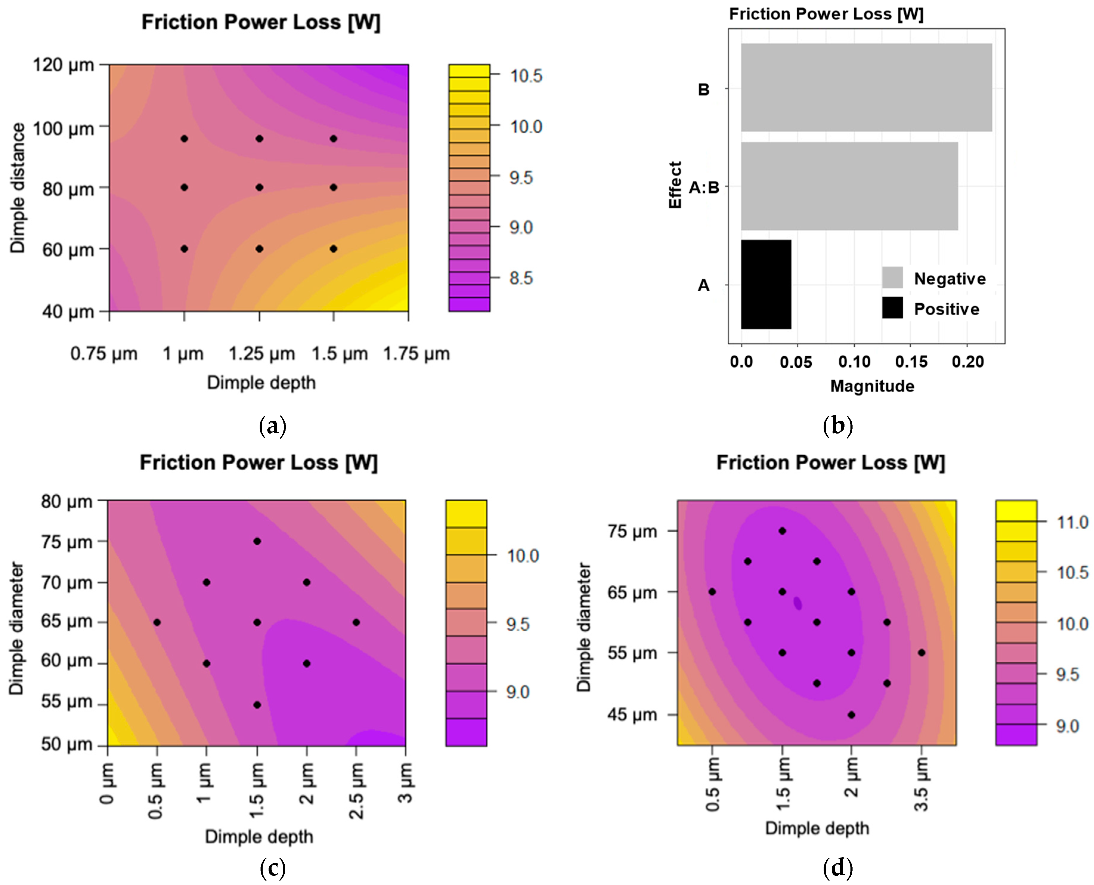
  • Utilizing a Box–Behnken experimental screening design, dimple distance was determined to have the largest influence over the system. A Face-Centered secondary model was introduced to understand the behavior of the system around the boundaries. Based on the insights of these steps, considering also some constraints arising from the utilized simulation workflow, an optimal dimple distance of 80 µm was chosen for further experimentation.
  • A Central Composite Circumscribed design was then introduced to find an optimal depth and diameter configuration for a dimple distance of 80 µm. The initial nine-point model was extended with additional six points to find a local optimum, which is accepted to be a sweet spot, based on the findings of previous experimental investigations. An 8.3% improvement compared to the untextured surface was demonstrated using a depth of 2 µm, a center-to-center distance of 80 µm, and a diameter of 60 µm.
The existence of a global optimum other than the presumed local optimum presented in this study resulting in a lower friction power loss cannot be ruled out; however, given the examined variables, the presented optimum is a parameter configuration that can be transferred to the available laser equipment. Consequently, it is not only interpretable within the simulation environment but can also be validated through future tribometer experiments.

Author Contributions

Conceptualization, G.L. and A.L.N.; methodology, G.L., D.P. and A.L.N.; software, L.B. and D.P.; validation, L.B. and D.P.; investigation, G.L. and D.P.; resources, A.L.N.; data curation, L.B. and D.P.; writing—original draft preparation, G.L. and D.P.; writing—review and editing, A.L.N.; visualization, D.P.; supervision, A.L.N.; project administration, A.L.N.; funding acquisition, A.L.N. All authors have read and agreed to the published version of the manuscript.

Funding

This article is published in the framework of the project “Production and Validation of Synthetic Fuels in Industry-University Collaboration”, project number “ÉZFF/956/2022-ITM_SZERZ”. This study was partially supported by the EKÖP-24-3-I-SZE-76 UNIVERSITY RESEARCH FELLOWSHIP PROGRAM of the Ministry for Culture and Innovation from the source of the National Research, Development and Innovation Fund.

Institutional Review Board Statement

This study does not concern ethical questions related to experimentation on humans and animals.

Informed Consent Statement

No personal data were collected during the experiments.

Data Availability Statement

Data for the study are available upon request from the corresponding author.

Acknowledgments

The authors would like to express their gratitude to Attila Schweighardt and Jan Rohde-Brandenburger for their support.

Conflicts of Interest

The authors declare no conflicts of interest.

Abbreviations

The following abbreviations are used in this manuscript:
SAESociety of Automotive Engineers
RaArithmetic mean roughness in µm
DoEDesign of Experiments
CCCCentral Composite Circumscribed (experimental design)
FCDFace-Centered Design (experimental design)
R2Coefficient of determination

References

  1. Sonawane, U.; Agarwal, A.K. Engine Emission Control Devices for Particulate Matter and Oxides of Nitrogen: Challenges and Emerging Trends. In Novel Internal Combustion Engine Technologies for Performance Improvement and Emission Reduction; Singh, A.P., Agarwal, A.K., Eds.; Springer: Singapore, 2021; pp. 197–220. [Google Scholar] [CrossRef]
  2. Morgunov, B.; Chashchin, V.; Gudkov, A.; Chashchin, M.; Popova, O.; Nikanov, A.; Thomassen, Y. Health Risk Factors of Emissions from Internal Combustion Engine Vehicles: An Up-to-Date Status of the Problem. Здoрoвье Населения И Среда Обитания-ЗНиСО/Public Health Life Environ. 2022, 30, 7–14. [Google Scholar] [CrossRef]
  3. Sitdikov, V.M.; Dudareva, N.Y.; Ishemguzhin, A.A.; Dautov, I. Emission Control and Reduction in the Combustion Chamber of an Internal Combustion Engine. Trudy NAMI 2023, 4, 83–95. [Google Scholar] [CrossRef]
  4. Vorob’ev, Y.V.; Dunaev, A.V. Reducing Motor Fuel Consumption Using Mechanochemical Methods. J. Mach. Manuf. Reliab. 2019, 48, 268–274. [Google Scholar] [CrossRef]
  5. Galovic, J.; Hofmann, P. Thermochemical Heat Storage for Consumption Reduction in Internal Combustion Engines. MTZ Worldw. 2019, 80, 134–139. [Google Scholar] [CrossRef]
  6. El Mansori, M.; Goeldel, B.; Sabri, L. Performance impact of honing dynamics on surface finish of precoated cylinder bores. Surf. Coat. Technol. 2013, 215, 334–339. [Google Scholar] [CrossRef]
  7. Zhmud, B.; Tomanik, E.; Grabon, W.; Schorr, D.; Brodmann, B. Optimizing the piston/bore tribology: The role of surface specifications, ring pack, and lubricant. In SAE Technical Paper; SAE: Warrendale, PA, USA, 2020. [Google Scholar] [CrossRef]
  8. Yousfi, M.; Ţălu, Ş. The impact of helical slide honing on surface microtexture compared to plateau honing process through relevant characterization methods. Microsc. Res. Tech. 2022, 85, 2397–2408. [Google Scholar] [CrossRef]
  9. Kim, E.S.; Kim, S.M.; Lee, Y.Z. The effect of plateau honing on the friction and wear of cylinder liners. Wear 2018, 400, 207–212. [Google Scholar] [CrossRef]
  10. Baby, A.K.; Rajendrakumar, P.K. Influence of honing angle on tribological behaviour of cylinder liner–piston ring pair: Experimental investigation. Tribol. Int. 2022, 167, 107355. [Google Scholar] [CrossRef]
  11. Specification and Measurement of Plateau Honed Surfaces. Available online: https://digitalmetrology.com/tutorials/plateauhoning (accessed on 10 April 2025).
  12. Rastegar, F.; Craft, A.E. Piston ring coatings for high horsepower diesel engines. Surf. Coat. Technol. 1993, 61, 36–42. [Google Scholar] [CrossRef]
  13. Pawlus, P.; Koszela, W.; Reizer, R. Surface texturing of cylinder liners: A review. Materials 2022, 15, 8629. [Google Scholar] [CrossRef]
  14. Du, F.; Zhang, Y.; Gao, Z.; Wang, J.; Yang, Y.; Wang, J.; Shen, Y. Research on the Carbon Emission Reduction of Internal Combustion Engines by Reducing Friction Work. E3S Web Conf. 2024, 546, 1016. [Google Scholar] [CrossRef]
  15. Bhutta, M.U.; Najeeb, M.H.; Abdullah, M.U.; Shah, S.R.; Khurram, M.; Mufti, R.A.; Arshad, M. Experimental Investigation of Engine Valve Train Friction Considering Effects of Operating Conditions and WPC Surface Treatment. Materials 2023, 16, 3431. [Google Scholar] [CrossRef] [PubMed]
  16. Laki, G. A Review on Friction Reduction by Laser Textured Surfaces. Tribol. Online 2022, 17, 318–334. [Google Scholar] [CrossRef]
  17. Woś, S.; Koszela, W.; Dzierwa, A.; Pawlus, P. Effect of Zonal Laser Texturing on Friction Reduction of Steel Elements in Lubricated Reciprocating Motion. Materials 2024, 17, 2401. [Google Scholar] [CrossRef]
  18. Li, Q.; Lu, R.; Tani, H.; Kawada, S.; Koganezawa, S.; Liu, X.; Cong, P. Tribofilm Formation and Friction Reduction Performance on Laser-Textured Surface with Micro-Grooved Structures. Lubricants 2024, 12, 91. [Google Scholar] [CrossRef]
  19. Turali, N.; Saleem, S.; Muddada, V.; Naik, D.K.; Sreeramulu, D.; Duppala, A.; Dilawar, M.; Radha, K. Enhancing Tribological Performance of AISI 52100: The Role of Laser Surface Texturing in Dry and Lubricated Conditions. Eng. Res. Express 2024, 6, 045517. [Google Scholar] [CrossRef]
  20. Zhang, Y.; Jia, X.; He, K.; Dong, X.; Wang, Z.; Liao, K. Lipophilic and Friction Properties of 20CrMnTi Steel with Laser-Induced Texturing. Tribol. Int. 2024, 194, 109550. [Google Scholar] [CrossRef]
  21. Butler-Smith, P.; Burtt, N.; See, T. The Friction of Surface Textured Cylinder Liner Segments Modified by Direct Laser Writing and Direct Laser Interference Patterning Processes. J. Manuf. Process. 2024, 117, 366–374. [Google Scholar] [CrossRef]
  22. Ju, W.S.; Kim, C.H.; Han, K.S.; Yun, T.H.; Ro, K.I.; Ho, K.M.; Rim, K.C. Laser Surface Texturing in Graphite Cast Iron for Reduction of Friction and Wear: Effect of Dimple Density. Res. Sq. 2024, submitted. [CrossRef]
  23. Ancona, A.; Gaudiuso, C.; Volpe, A.; Mezzapesa, F.P.; Putignano, C.; Carbone, G. Laser Surface Texturing for Superhydrophobic, Icephobic and Friction Reduction Functionalization. In Proceedings of the IOP Conference Series: Materials Science and Engineering; IOP Publishing: Bristol, UK, 2023; Volume 1296, p. 012042. [Google Scholar] [CrossRef]
  24. Cheng, H.; Zhou, F.; Fei, Z. Dry Friction Properties of Friction Subsets and Angle Related to Surface Texture of Cemented Carbide by Femtosecond Laser Surface Texturing. Coatings 2023, 13, 741. [Google Scholar] [CrossRef]
  25. Berardo, A.; Borasso, M.; Gallus, E.; Pugno, N.M. Finite Element Simulations and Statistical Analysis for the Tribological Design of Mutually Textured Surfaces and Related Experimental Validation. J. Tribol. 2024, 147, 3. [Google Scholar] [CrossRef]
  26. Narayanan, V.; Singh, R.; Marla, D. A 3D Computational Model of Nanosecond Pulsed Laser Texturing of Metals for Designing Engineered Surfaces. J. Manuf. Sci. Eng. 2024, 146, 5. [Google Scholar] [CrossRef]
  27. Chua Abdullah, M.I.H.; Abdollah, M.F.B.; Amiruddin, H.; Tamaldin, N.; Mat Nuri, N.R. Optimization of Tribological Performance of hBN/Al2O3 Nanoparticles as Engine Oil Additives. Procedia Eng. 2013, 68, 313–319. [Google Scholar] [CrossRef]
  28. Iruthaya Raj, J.M.; Manisekar, K.; Gupta, M. Central Composite Experimental Design Applied to the Dry Sliding Wear Behavior of Mg/Mica Composites. J. Tribol. 2018, 141, 011603. [Google Scholar] [CrossRef]
  29. Salahshoori, I.; Seyfaee, A.; Babapoor, A.; Neville, F.; Moreno-Atanasio, R. Evaluation of the Effect of Silica Nanoparticles, Temperature and Pressure on the Performance of PSF/PEG/SiO2 Mixed Matrix Membranes: A Molecular Dynamics Simulation (MD) and Design of Experiments (DOE) Study. J. Mol. Liq. 2021, 333, 115957. [Google Scholar] [CrossRef]
  30. Laki, G.; Boros, L.; Nagy, A.L. Topography Pre-Treatment of Laser-Textured Surfaces for Friction Simulation in AVL Excite. Eng. Proc. 2024, 79, 95. [Google Scholar] [CrossRef]
  31. Németh, P.; Hanula, B.; Nagy, A.L. Smart Hybrid Energy Management System in a Passenger Car. Chem. Eng. Trans. 2023, 107, 457–462. [Google Scholar] [CrossRef]
  32. Etsion, I.; Sher, E. Improving fuel efficiency with laser surface textured piston rings. Tribol. Int. 2009, 42, 542–547. [Google Scholar] [CrossRef]
  33. Yin, B.; Xu, B.; Jia, H.; Hua, X.; Fu, Y. Experimental research on the frictional performance of real laser-textured cylinder liner under different lubrication conditions. Int. J. Engine Res. 2021, 23, 693–704. [Google Scholar] [CrossRef]
  34. Akbarzadeh, A.; Khonsari, M.M. Effect of untampered plasma coating and surface texturing on friction and running-in behavior of piston rings. Coatings 2018, 8, 110. [Google Scholar] [CrossRef]
  35. Shen, C.; Khonsari, M.M. The effect of laser machined pockets on the lubrication of piston ring prototypes. Tribol. Int. 2016, 101, 273–283. [Google Scholar] [CrossRef]
Figure 1. Surface topographies of the original cylinder (a) and ring (b), along with two modified ring surfaces featuring dimpled textures (c,d).
Coatings 15 00528 g001
Figure 2. (a) The first 3D Box–Behnken design with 13 simulation points used for mapping the effects of the variables, with the central point (A = 1 µm, B = 160 µm, C = 60 µm) repeated three times; (b) Pareto analysis of the first model; (c) the second 3D Box–Behnken design for mapping the effects of the variables; (d) Pareto analysis of the second model.
Coatings 15 00528 g002
Figure 3. (a) Evaluation of the effect of changing parameter B in the boundary model (plotted using coded units, labelled as physical); (b) Pareto analysis of the boundary model; (c) Central Composite Circumscribed model for mapping the optimum (plotted using coded units, labelled as physical); (d) enhanced Central Composite Circumscribed model (plotted using coded units, labelled as physical).
Coatings 15 00528 g003
Table 1. Best-performing set of parameters based on the Face-Centered Design.
“A” (Depth)“B” (Distance)“C” (Diameter)Simulated
Friction Power Loss
1.5 µm80 µm70 µm8.976 W
1.5 µm80 µm60 µm9.001 W
Table 2. Parameter sets of the Central Composite Circumscribed design.
“A” (Depth)“B” (Distance)“C” (Diameter)
0.5 µm80 µm
(not changed in this study)
65 µm
1 µm60 µm
1 µm70 µm
1.5 µm55 µm
1.5 µm65 µm
1.5 µm75 µm
2 µm60 µm
2 µm70 µm
2.5 µm65 µm
Table 3. Parameter sets of the extended Central Composite Circumscribed design.
“A” (Depth)“B” (Distance)“C” (Diameter)
2 µm80 µm
(not changed in this study)
50 µm
2.5 µm45 µm
2.5 µm55 µm
3 µm50 µm
3 µm60 µm
3.5 µm55 µm
Table 4. Characteristics of the lowest friction power loss values achieved with discrete variables.
“A” (Depth) “B” (Distance)“C” (Diameter)Model PredictionSimulation ResultDeviation
1.5 µm80 µm60 µm9.028 W9.001 W−0.3%
2 µm80 µm65 µm9.027 W9.022 W−0.06%
Disclaimer/Publisher’s Note: The statements, opinions and data contained in all publications are solely those of the individual author(s) and contributor(s) and not of MDPI and/or the editor(s). MDPI and/or the editor(s) disclaim responsibility for any injury to people or property resulting from any ideas, methods, instructions or products referred to in the content.

