Article

Micromechanical Properties and Tribological Performance of Mo, Cr, and Ta Coatings Obtained by Cathodic Arc-Deposition

1
Department of Aircraft Design, State University “Kyiv Aviation Institute”, 1, Liubomyra Huzara Ave, 03058 Kyiv, Ukraine
2
M. K. Yanhel State Design Bureau “Pivdenne”, 3 Kryvoriz’ka Street, 49008 Dnipro, Ukraine
3
G.V. Kurdyumov Institute for Metal Physics of the NAS of Ukraine, 36 Academician Vernadsky Boulevard, 03142 Kyiv, Ukraine
4
E.O. Paton Electric Welding Institute of the NAS of Ukraine, 11 Kazymyr Malevych Street, 03150 Kyiv, Ukraine
*
Author to whom correspondence should be addressed.
Coatings 2025, 15(3), 358; https://doi.org/10.3390/coatings15030358
Submission received: 27 February 2025 / Revised: 16 March 2025 / Accepted: 17 March 2025 / Published: 19 March 2025

Abstract

:
The aim of the study is a comparative analysis of micromechanical and microtribological properties of the cathodic arc-deposited Mo, Cr, and Ta coatings using nanoindentation and scratch test techniques as well as a microtribological dry sliding test with wear tracks post-examination and worn volume determination using interference profilometry. A new scratch test technique based on the statistical processing of registered sclerograms during a multi-pass scratch test well adopted for the scratch resistance assessment of rough surfaces is suggested. New approaches to microtribological testing based on the indentation tester equipped with an additional precision rotational stage are proposed, which could fill the gap between macro- and nano-scale. X-ray diffraction analysis reveals the structure of the studied coatings and phase compositions of the coating-substrate interface.

Graphical Abstract

1. Introduction

Nowadays, several newly developed materials have become popular for various applications in machine building and transportation. Nonetheless, carbon steel remains the most widely used material in carriage building and construction industries owing to its low cost and satisfactory strength [1,2]. However, the combined effect of mechanical loads and corrosive environments may lead to a significant reduction in the service life of machine parts and equipment made of metallic materials. Therefore, enhancing the quality and operational life of steel products without replacement with expensive high-alloyed steels is relevant and demands further studies.
Since the surface-related properties of steel components, such as corrosion, wear, and fatigue, are largely dependent on the conditions of their surface [1,2,3], additional surface modification involving severe plastic deformation [4,5], surface alloying [6,7,8,9], and/or coating depositions [10,11,12,13,14] is attractive and demanded [15,16].
Formation of various types of protective coatings is seemingly the most effective modification method, especially accounting for the protective outcomes and preservation of the specified properties of the substrate (the core of the steel product). Depositions of chromium or chromium alloys using chromium plating and chromizing are the cheapest and most widely applicable methods to impart many physical and chemical properties to the metal’s surface [17]. Chromium electroplating [18,19] and electric discharge surface alloying (EDSA) [7] are commonly used techniques. However, the inherent brittleness of the electroplated chromium coatings [15] and the presence of defects and/or residual tensile macro-stresses [15,20] may cause substantial worsening of the covered component properties. Additionally, considering the high toxicity of the chromium chemicals [21], any replacements of the chromium by other elements are attractive and aid in environmental protection. Recently, the surface alloying/coating of steel components with molybdenum or tantalum was reported as a good alternative to toxic chromium [8,9,10,11] since these elements eliminate the harmful effects of chromium and improve the wear and corrosion properties [22].
Molybdenum and tantalum are the refractory metals of high interest in aerospace, nuclear, defense, and biomedicine fields due to their good workability at room temperature, satisfactory mechanical properties, and corrosion resistance. Currently, additive manufacturing (AM) or powder metallurgy (PM) technologies offer novel opportunities for processing refractory materials, which are cast with difficulty. However, AM of refractory metals such as pure tantalum, pure molybdenum, pure tungsten, and their alloys is also somewhat difficult [23,24,25,26,27] due to its high melting point and the affinity with carbon, hydrogen, and oxygen during processing. The concentration of interstitial impurities at the grain boundaries may facilitate severe wear, surface delamination, and brittle fracture [23,24,25]. Additionally, a high ductile-to-brittle transition temperature may result in cracking within the 3D-printed part and greatly reduce the material’s strength and fracture toughness [26,27].
Several studies of the Fe-Ta [8,10,28,29,30] and Fe-Mo [11,31] systems were made to assess the influence of Mo and Ta on steel properties. Various methods, such as electro-deposition [32], laser surface alloying [33], EDSA [9], low-pressure plasma spraying [34], and double glow discharge plasma metallizing [35], were employed to produce the Fe-Mo layers on steel components. Thus, the production of crack-free Mo and Ta arc-deposited coatings can be beneficial in protecting steel products. At the same time, one should account for the secondary phases, which may deteriorate the coating-substrate interfacial strength in addition to the influence of the above-mentioned interstitial impurities. Alloys of the Fe-Mo system are characterized by several precipitates, such as λ (Fe2Mo), µ (Fe7Mo6), R (Fe3Mo2), σ (FeMo) phases, and (Fe,Mo)3C carbides [9,36,37,38] and even an amorphous phase [32] depending on the production and annealing regimes. Conversely, the materials of the Fe–Ta system were reported to endure the solid-state reactions at moderate temperatures, leading to the formation of metastable crystalline and/or amorphous phases [28,29,30]. The main benefits of chromium, molybdenum, or tantalum as an alloying element relate to the high hardening ability, wear resistance, enhanced anti-corrosion protection, and high-temperature oxidation resistance of the Mo/Ta-alloyed layers [7,8,9,10,12,33,34,35,36,37,38]. Additionally, recent studies were directed at the tailoring magnetic properties of Ta film and Fe-Ta metastable alloys in either crystalline or amorphous structures, and a few systems comprising both bcc and amorphous states [29].
Vacuum arc deposition produces coatings from any metals as well as electrically conductive elements [39]. Such coatings with a thickness of 15 μm could replace galvanic coatings with a thickness of 40–50 μm, which are usually used in mechanical engineering. Higher corrosion resistance of vacuum-arc coatings is achieved due to their high density and absence of pores and cracks. Cracks in galvanic coatings could be formed during the deposition process and then grow during operation with further component base material damage [40]. Better operational properties of vacuum-arc-deposited coatings can be explained by compressive stresses, which improve fatigue life.
Tribological performance and mechanical properties of coatings obtained by cathodic arc deposition depend on deposition parameters, i.e., the deposition temperature, discharge current, bias voltage, vacuum degree, presence of reactive gases, and materials used for the cathode and substrate. It should be noted that the majority of the research was carried out on thin composite coatings with a thickness of ≤3 µm [41]. At the same time, the coating thickness has a direct impact on the component’s operational life, and the aerospace, military, and many other industries require coatings with a thickness of ≥100 µm [11]. Special-purpose parts, such as combustion chambers of rocket engines, artillery barrels, etc., operate in severe conditions, such as high temperature and pressure together with an aggressive gas environment [42]. Coatings with high corrosion resistance, wear resistance, and high adhesion should be applied to protect such parts. In this article, we present a comparative analysis of micromechanical, sclerometric, and tribological investigations of Mo, Cr, and Ta coatings obtained by vacuum-arc deposition on a chromium-nickel-molybdenum steel substrate. Materials’ choice is determined by the fact that coatings made of refractory metals are most effective for component surface protection operating in extreme conditions.
Hardness, elastic properties, and creep, as well as wear resistance and friction coefficient, are the most important parameters that determine the coated component performance [43]. Nowadays, several instruments and methods for mechanical and tribological material characterization at different scales are available [44,45]. Depth-sensing indentation, also called instrumented indentation, found wide application in the scientific community for mechanical properties assessment of coating and bulk materials in small volumes. Scratch testing is extensively used for evaluating adhesion and other mechanical and microtribological parameters [46]. The standard pin-on-disc test method is widely applied for wear and friction experiments [47] at the macro level. Despite the variety of existing methods and instruments, the development of new approaches, methods, and protocols for material characterization is an actual task. It was noted that the further development of scratch tests relates to the development of new protocols of data analysis [48].
In the present article, a new approach to the scratch test method for characterizing the coatings’ mechanical properties is proposed. The key idea of the method is based on the correlation between the scratch profiles registered during multi-scratch testing at a constant load. Moreover, a new approach for microtribological testing on the base of the indentation tester is proposed and described. The developed techniques were used for characterizing the micromechanical and microtribological properties of the cathodic arc-deposited Cr, Mo, and Ta coatings. Moreover, indentation tests, X-ray analysis, and white-light interferometry were used to characterize the coatings.

2. Materials and Methods

Samples with rectangular shapes of 18 × 34 × 10 mm from chromium-nickel-molybdenum steel ground on a surface grinding machine to roughness Ra 0.3 μm were used as a substrate. After grinding, the substrates were degreased and cleaned. Before the coating deposition, the substrate surfaces were bombarded for 10 min by coating material ions at a potential difference of 800 V and an ion current of 5 A in the vacuum.
Coatings were deposited by vacuum arc evaporation of cylindrical cathodes followed by the condensation of the ionized vapors on a steel substrate. The cathodes of 50 mm in diameter were made of refractory metals, i.e., tantalum with a purity of 99.95%, molybdenum with a purity of 99.95%, and chromium with a purity of 99.96%.
During the coatings’ deposition process, the residual pressure in the vacuum chamber was maintained to be not higher than 1 × 10⁻⁵ Torr. The arc discharge currents leading to the cathodes’ evaporation were 75 A, 100 A, and 220 A for chromium, molybdenum, and tantalum cathodes, respectively. The thicknesses of the Mo, Ta, and Cr arc-deposited coatings were measured to be 33 μm, 36 μm, and 46 μm, respectively. The substrate temperature during the deposition process was maintained in the range of 350–360 °C.
A ‘Θ–2Θ’ XRD analysis using a Rigaku Ultima IV XRD apparatus (Rigaku, Tokyo, Japan) with a Cu Kα radiation (λ = 1.5406 Å) was used to examine the crystal structure and phase composition of produced Mo, Cr, and Ta coatings. The X-ray scanning step length was 0.04°, and the residence time was 4 s. The crystallite size D and lattice microstrains η were also evaluated using the Williamson–Hall approach and Scherrer’s equation [49,50,51]: β = (K λ / D cosθ) + η tgθ, where K is the constant (K = 0.9, assuming that all the grain sections are spherical), λ is the X-ray wavelength, θ is the diffraction angle, β = (B2 − b2)1/2 is the physical broadening (FWHM) of the peak, B is the FWHM obtained from the coatings, and b is the FWHM of instrumental broadening. The full widths at half maximum (FWHM) of the (110), (200), (211), (220), and (310) reflections were analyzed. The instrumental broadening b was preliminarily determined using the Si etalon powder.
The surface morphology and chemical composition of the arc-deposited coatings and scratch tracks were characterized by scanning electron microscopy (SEM) and energy dispersive X-ray spectroscopy (EDS) using a TESCAN Mira 3 LMU microscope (TESCAN SRO, Brno, Czech Republic) equipped with a BRUKER EDS microanalyzer (BRUKER Corp., Billerica, MA, USA).
Surface topography measurement of the deposited coatings with surface roughness parameters evaluation and the wear track morphology analysis with the determination of the volume of the material worn were carried out using a non-contact interference profilometer “Micron-alpha” [52].
The comparative study of micromechanical and microtribological properties of the obtained coating was performed using a multifunctional indentation tester “Micron-gamma” [53,54]. Micromechanical properties were measured using the depth-sensing indentation and multi-pass scratch test techniques while microtribological testing was performed employing the indentation tester supplemented by the developed precision rotational stage. The “Micron-gamma” indentation tester was equipped with a two-coordinate motorized manually rotated stage with a movement speed of 20–80 μm/s. The indenter loading was carried out by a linear non-contact electromagnetic loading unit with a maximum force of 50 N. Normal and tangential displacements of the indenter were registered by inductive sensors with nanometric resolution. The instrument was equipped with an integrated microscope for accurate positioning of the indenter and image registration. Precise indenter positioning is realized by rotation of the loading unit and microscope axes around the general instrument axis.

2.1. Micromechanical Characterization

Micromechanical properties such as hardness, reduced elastic modulus, and creep were measured using a Berkovich indenter at a maximum load of 500 mN and a constant loading rate of 50 mN/s with automatic recording of the load (P) on the indenter and its penetration depth (h). The registered indentation diagrams were corrected according to the methodology described in [55]. Hardness and elastic modulus were calculated according to the Oliver and Pharr method [56], later accepted as an international standard [57]. Microcreep was measured by recording the indenter penetration depth during holding at a load of 500 mN for 10 s.

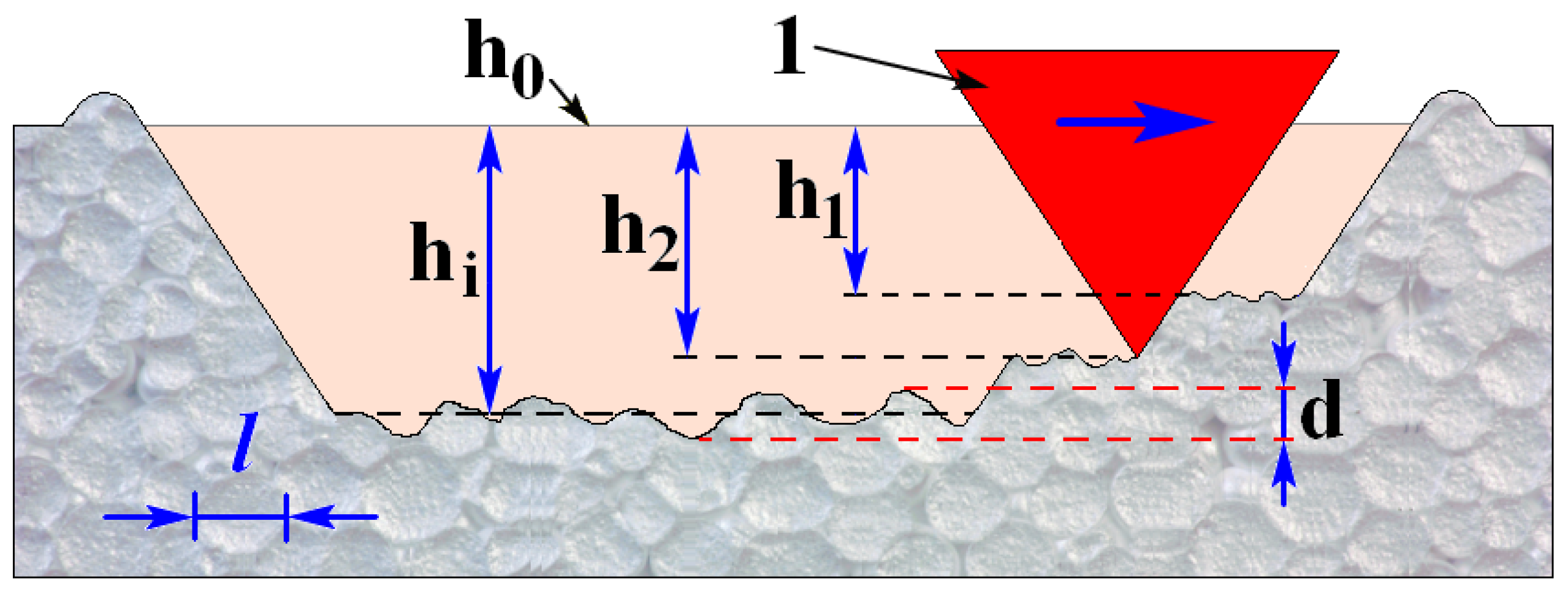
2.2. Sclerometry Testing

Sclerometric characteristics, such as scratch hardness, wear resistance, and fracture resistance, were studied by multi-pass scratch testing with a Berkovich indenter at a constant load of 500 mN and a movement speed of 20 μm/s.
The multi-pass scratch experiment procedure sequence is shown in Figure 1. In the first stage, a profilogram of the initial surface (h0) was registered at a load of 5 mN. Such a small load practically does not damage the surface and does not distort the initial profile, but it provides the indenter contact with the surface. After registration of the initial surface profile, seven repeated scratches were made at a load of 500 mN on indenter 1, returning to the initial position each time. Moreover, during the backward movement of the indenter, the profilograms of the generated scratches (h1 − hi) were recorded at the load on the indenter of 5 mN.
During the multi-pass scratch test, the sclerograms (i.e., the normal indenter displacement under the load) and residual scratch profilograms were recorded for each scan. Statistical analysis of the obtained results could provide additional information for micromechanical properties characterization of the studied material, in particular:
  • Mean residual scratch depth after the first pass h1 can characterize the average hardness along the scratch path, and its dispersion dh1 is the hardness variation. To eliminate the influence of initial surface relief, the profilogram of the original surface h0 was subtracted from the registered scratch depth h1. The scratch hardness was calculated using the formula Hs = 3.138R/b2, where the scratch width is b = 7.53 × h1 from geometric considerations for the Berkovich indenter.
  • The dependence of the mean residual scratch depth on the number of repeated passes can characterize the scratch resistance or wear resistance of a material.
  • The ratio of the increase in the mean value of a residual scratch depth to the mean depth of the first pass can characterize the material plasticity. The dimensionless coefficient can be used as a plasticity indicator: kpl = (hi − h1)/h1.
  • The correlation relationship r1 between the profilogram of the initial surface h0 and subsequent residual scratch depth profilograms hi, recorded for each pass, can characterize the resistance to a fatigue failure.
  • The correlation relationship r2 between the profilograms of adjacent passes, e.g., (h1 and h2), (h2 and h3), etc., can characterize the strain hardening tendency.

2.3. Microtribological Characterization

The comparative analysis of the microtribological performance of the arc-deposited Mo, Cr, and Ta coatings was carried out in a “pin-on-disk” mode using a conical diamond indenter with a tip radius of 50 μm under the constant load of 500 mN.
To provide rotational movement of the specimen, the independently driven precision rotational stage was designed and manufactured (Figure 2), which was then installed on the motorized stage of the indentation tester “Micron-gamma”. The developed rotational stage provides the specimen to accomplish a rotational movement at a speed range of 150–900 rpm relative to the indenter, which was used as the counter-body. The load on the indenter was applied by the loading unit of the indentation tester, and friction force was measured using a high-precision sensor of the tester.
The rotating stage 3 is connected to the massive steel casing 1 through the precision bearings, and it is driven by a micro-electrical motor 5 through a rubber belt. The microtribological tests could be performed with very small track diameters ranging from 50 to 3000 μm. This significantly reduces the torque moment and allows fixing the studied sample 2 by pressing it with a hand press through plasticine or wax 4. The proposed method simplifies specimen fixation and provides strict parallelism of the tested surface, which, in turn, crucially reduces vertical beating during the sample rotation. Moreover, a small track diameter significantly reduces the friction path and prevents quick wear of the counter-body. Additionally, the suggested approach minimizes the wear-induced changes in the indenter geometry, extends the indenter’s operational life, and provides results repeatability.
To carry out the microtribological test, the developed rotational stage with a fixed specimen was manually installed on the motorized stage center of the hardness tester. After installation of the sample, the microscope integrated with the hardness tester was focused on the tested specimen surface (Figure 3a). After focusing the microscope, the micro-electrical motor was turned on, and the specimen started its rotation beneath the microscope. During the specimen rotation, the moving parts are blurred, and the stationary center of the rotation can be easily detected using the microscope. Then, knowing the location of the rotation center relative to the mark (a crossed circle in Figure 3b), it is easy to make them coincide by controlling the two-coordinate motorized stage of the hardness tester. Further, the two-coordinate stage should be moved at the required distance from the center, which will be equal to the radius of the friction track. This new position will be the indenter contact point with the studied surface (Figure 3c). After installation of the indenter on the sample surface, the required test parameters could be chosen, and the microtribological test would start after turning on the electrical motor.
The developed independently driven rotational stage and methodology of indenter installation for the track formation of needed diameters allow for the expansion of the hardness tester application for microtribological testing. Moreover, the high-resolution sensors for the depth or friction force registrations of the indentation tester could be used for the data collection throughout the experiment.

3. Results and Discussion

Figure 4 illustrates X-ray diffraction patterns registered over the 2θ range of 30–125°. As seen, mainly reflexes related to the studied coatings with BCC lattice are observed. Thus, some low-intensity peaks of the steel substrate (bcc-Fe) are also visible, indicating deep enough penetration of the X-rays through the arc-deposited coatings (Figure 5a,b,d–f). No significant amounts of additional phases are observed, indicating that the arc deposition regimes used allow producing pure metallic coatings. Additionally, the grains in the near-surface layers of the Ta and Mo coatings are oriented with the most dense (110) atomic plane parallel to the outmost surface, while the Cr coating contains two sorts of grains with equally high intensity of (110) and (200) diffraction peaks. Generally, the denser the plane, the higher its hardness and wear resistance, and the higher the anti-corrosion properties.
To reveal probable formation of additional phases at the coating-substrate interface or in the lower layers of the deposited films due to the bombardment of the steel substrate by the Cr+, Mo+, and Ta+ ions, the fragments of XRD patterns were analyzed using the logarithmic intensity axes, which allow revealing the low-intensity traces (Figure 5a–c). This information is important considering the adhesion of the coating, which may be affected by the secondary phases depending on their lattice structure, properties, and volume fraction. Thus, the Cr-Fe interface contains the traces of only one additional Fe-Cr phase with a tetragonal lattice (t-FeCr) (Figure 5a), which cannot deteriorate the adhesive strength. Beneath the Ta arc-deposited coating, the traces of two phases, i.e., ε-phase (with a MgZn2 lattice structure) and μ-phase (with a Fe7W6 lattice structure) [28,29], were revealed (Figure 5c). These phases are also unable to reduce the adhesion strength due to their negligible volume fraction. Considering the interface between the Mo arc-deposited coating and steel substrate, one may expect the appearance of several additional phases, i.e., λ (Fe2Mo), µ (Fe7Mo6), R (Fe3Mo2), σ (FeMo) phases, and (Fe,Mo)3C carbides (Figure 5b). A complex lattice structure of some of these phases facilitates their high misfit with the MoFe solid solution and Mo coating, and thus an increase in hardness may occur. Additionally, the μ and σ phases and complex carbides, which are commonly considered as being hard and brittle, may exert a deteriorative effect on the interface adhesion if their content were to further increase.
According to Bragg’s law, the lattice constants of the Cr, Mo, and Ta coatings were respectively calculated to be equal to 0.2891 nm, 0.315 nm, and 0.3317 nm. These values agree with the tabulated data. However, the lattice constants for the Cr and Ta coatings are higher than those reported for the ideal Cr (0.2884 nm) and Ta (0.3303 nm) lattices, indicating the formation of compressive residual stresses, which are known to be a beneficial factor in the sense of the enhanced operational properties (fatigue and wear behavior) of the coated materials since they may retard the crack propagation if they were initiated for some reasons. Conversely, the ideal match is observed for the experimental and tabulated Mo lattice constants. Considering similar deposition conditions, it can be explained by the stress relaxation. Analysis of the X-ray peaks broadening gives the estimated values of grain/crystallite size D and lattice microstrains η for the arc-deposited coatings. As assessed, the smallest grain size (D = 22 nm) and highest lattice microstrains (η = 0.39%) were formed in the Ta coating. The Mo and Cr coatings are characterized by a slightly larger D (68 nm and 123 nm, respectively) and lower η (0.16% and 0.24%, respectively). The lower grain size is known to be beneficial considering the resulting increase in hardness [58,59]. Even a plasticity of a material can be improved owing to the grain boundary sliding effect if the grain size drops less than 10–20 nm [59,60]. For the refractory metals, however, the grain boundaries may play a pole of sinks for penetrating oxygen. Thus, the oxygen-driven embrittlement might occur due to a higher probability of the grain boundary segregation of the oxygen atoms [26].
It is well known that finishing and polishing may affect the hardness, toughness, wear resistance, and other material properties [61]. Thus, all experiments were carried out on the specimen surfaces without any polishing or post-processing to avoid the probable masking of the coating properties. The 3D surface topographies of Ta, Mo, and Cr coatings were registered using an optical profilometer “Micron-alpha” (Figure 6). As seen, the surface reliefs are not systematic in different directions and orientations and have a high anisotropy, especially those of the Mo and Cr coatings. For quantitative surface topography analysis, the surface roughness parameters were calculated within registered areas. Due to high surface relief anisotropy, the surface roughness parameters were calculated along the baselines, which are located in different directions across 16 circle sectors. The obtained magnitudes of the surface roughness parameters are presented for all studied coatings in the circular diagram in Figure 6d.
Ten indentations were automatically made on each sample using a Berkovich indenter to minimize the influence of the high roughness of the coating surface. The distance between the indents was purposely maintained to be not less than 50 μm to avoid the error due to plastic deformation on the obtained hardness magnitude. Calculated values of the average indentation hardness HIT and reduced elastic modulus E are listed in Table 1. For comparison, the earlier measured values for pure metals are also given in this table (in the brackets) [62]. Table 1 also contains the values of scratch hardness Hs, fiction coefficient kfr, plasticity coefficient kpl, correlation coefficient r0–6, and the worn volumes V assessed after multi-pass scratch and pin-on-disk tests.
Averaged indentation curves for Ta, Mo, and Cr coatings are shown in Figure 7. Additionally, the creep behavior of the coatings was analyzed during the indenter holding under the load of 500 mN for 10 s. Measurements were performed at three different points of each coating surface. The creep graphs are also presented in the inset of Figure 7 as a dependence of the indenter penetration depth (under the constant load) versus time. Considering the creep curves, the Cr coating can be concluded to possess the highest resistance to the penetration of the indenter. It should be noted that the average depth of the indenter penetration into the sample surfaces was ~2 μm, which is much less than the coating thicknesses (Mo-coating of 33 μm thick, Cr—46 μm, and Ta—36 μm). Hence, the substrate did not influence the coating properties.
As seen, the hardness magnitudes are higher for the arc-deposited coatings in comparison with those reported for parent metals. The values of the instrumented hardness and reduced elastic modulus of the studied arc-deposited coatings can be positioned in the following ascending sequence: Ta, Cr, and Mo.
Sclerometric comparative assessment of the arc-deposited coatings was performed in multi-pass mode on the same trace at the constant indenter load. By repeated scratching, it is possible to simulate the friction processes and evaluate material behavior in the contact zone. Seven experimental profilograms recorded after each pass supplemented with the microscopic and SEM images of the formed scratches are presented in Figure 8. In the first experiment stage, the initial surface profiles were recorded (the upper lines in blue in the graphs). After that, the scratch was applied from the initial position with the indenter load of 500 mN. Then, while returning from the scratch end to the initial position, a profilogram of the scratch residual depth was recorded. Such a procedure was repeated seven times, and the scratch profiles formed after each pass were measured.
Analysis of the scratch test results shows that the tribological behavior of the arc-deposited coatings differs significantly. The scratch shape of residual depth profiles for each pass for the Cr and Mo coatings is very close to the initial surface. On the contrary, each profilogram for tantalum is sharply different from the previous one.
A quantitative evaluation of deformational behavior results was performed using statistical analysis. Figure 9a shows the dependence of mean residual scratch depth versus the number of passes. In addition, the correlation coefficient was calculated using the Pearson formula between the initial profilogram and the profilograms registered after each scratch pass (Figure 9b) and the correlation between adjacent profilograms (Figure 9c).
Analysis of the presented results shows that for Mo and Cr, most of the depth is formed after the first pass of 0.9 and 1.4 μm, respectively. The main mechanism of first scratch formation is the plastic deformation of surface layers by a hard tip during scratching at a constant load, and in the majority of cases, scratch depth is proportional to material hardness. For molybdenum (Mo), with each subsequent pass, the scratch depth gradually increases by 0.1 μm without visible chipping and spallation, as can be seen from the microphotographs presented in Figure 8b. For chromium coating, the depth increases faster at the beginning, and in the last passes, it practically does not increase. The dependence of the mean scratch depth on the number of repeated passes can characterize the scratch resistance or wear resistance of a material. Analysis of mean scratch depth evolution during multi-pass scratch testing shows that Mo coating has higher values of scratch hardness (4.3 GPa) compared to Cr coating (3.4 GPa) and higher wear resistance due to the lower rate of depth increase with each subsequent pass (Figure 9a). Unlike the Mo and Cr coatings, for the tantalum one, the depth changes chaotically with each subsequent pass, sometimes increasing and decreasing. In this case, the separation of the wear debris, which was located along the scratch, was observed in the optical image (Figure 8c). Such fluctuation of mean scratch depth could be explained by the adhesive nature of the wear process. During scratching, wear debris adheres to the indenter and then forms transfer particles, which later stick under the high local contact pressure to the other area of a surface along the scratch (Figure 8c). It should be noted that heavy shearing of transferred material has a great impact on mean profile depth. Due to high-profile fluctuations, we do not use this information for scratch hardness characterization of Ta coating. The observed features of the scratch track appearances, depths, and uniformity are related to the mechanical properties and microstructure of the coatings and well correlated with indentation test results. Indeed, higher magnitudes of hardness and elastic modulus of the Cr and Mo coatings facilitate the formation of bright, smooth, and straight-edged tracks. Conversely, a softer Ta coating with a higher plasticity, which is provided by the smallest XRD-assessed grain size (22 nm), experienced a strong adhesive interaction with the diamond indenter, resulting in severe adhesive wear with material transfer, causing dramatic and unpredictable changes in scratch profiles (Figure 9c).
Graphs of the correlation of each pass profile regarding the initial surface profile can characterize the resistance to a low-cycle micro-fatigue failure (Figure 9b). The longer the original material surface can withstand external repeated loads without deformation, the higher the fatigue resistance. The graph shows that for the Ta coating, the connection is absent, i.e., scratch profiles change dramatically and non-monotonously after each pass. This can occur during the catastrophic failure of the outmost surface layer of the coating with the separation of particles, which is confirmed by wear debris located along the scratch as well as significant material transfer along the scratch. For the molybdenum coating, the correlation with the original profilogram is lost smoothly, reaching a value of r0–6 = 0.4 by the last pass (Figure 9b). This indicates smooth changes in the scratch shape during cyclic scans, possibly associated with smoothing the micro-irregularities owing to a high hardness/elasticity supplemented by a high enough plasticity. For the chromium coating, the correlation with the original profilogram is observed to be even higher (r0–6 = 0.83), i.e., the profilogram shape of the last scratch repeats the original profile with a higher probability, which may indicate the highest resistance to a micro-fatigue failure among studied coatings.
Additionally, the profilograms of the scratches registered after each pass for the Cr and Mo coatings are very similar too, i.e., they have a high degree of correlation between neighboring profilograms (Figure 9c). After the most marked change at the first scratch, the further scratch residual depths of the Cr and Mo coatings change slowly, indicating a higher resistance to surface damage and wear. On the contrary, the lack of correlation between the neighboring profilograms of the scratch tracks formed on the Ta coating indicates catastrophic surface failure and repetitive adhesion of the wear debris. In addition, this is accompanied by the separation of material particles, which are visible in the light optical microscopy images of the scratch (Figure 8c). The high correlation relationship between the profilograms of adjacent passes for Mo and Cr coatings can be explained by the strain hardening behavior of coatings due to the formation of mechanically modified layers with refined microstructure.
SEM observations of the scratch tracks shown in Figure 10a–c supplemented with the EDS spectra allow discriminating wear behavior of the studied coatings in more detail. The scratch tracks’ morphologies of the Cr (Figure 10a) and Mo (Figure 10b) coatings are similar, and both tracks are limited by lateral pile-ups with slightly ragged edges. However, considering the occurrence of transverse microcracks, the Mo coating seems to experience more micro-fatigue and is well correlated with scratch test results. Additionally, some continuous sliding marks with plastically deformed grooves and small cracks can be found on the scratch surface of the Mo coating (Figure 10b). On the contrary, the morphology of the scratch track formed on the Ta coating is distinctly different (Figure 10c). For the Ta coating, a much more pronounced adhesion to the indenter results in severe material transfer and the formation of large wave-like inflows, ridges, smeared areas, and significant damage.
The chemical compositions of the selected areas in the scratch tracks (indicated as S1) and native coatings (S2) are listed in the appropriate insets in the EDS spectra shown in Figure 10. As seen, all the studied coatings have no unexpected additives but contain just the main material (Cr, Mo, or Ta) and some quantity of carbon and oxygen. Despite some accuracy limitations regarding the EDS-based determination of the low atomic radius elements’ content (i.e., C and O), the obtained EDS spectra allow catching the trends of the elements content changes induced by scratch tests of the Cr, Mo, and Ta arc-deposited coatings by comparison of their chemical compositions gathered at the scratch tracks (aS1, bS1, and cS1) and native coatings (aS2, bS2, and cS2). As seen, there is about a 15% increase in the oxygen content in the scratched Cr and Mo coatings, while the Ta coating demonstrates drastic oxygenation (~200%). The predominance of the operative wear mechanisms is also affected by the carbon content. In the case of the Ta and Mo coatings, the carbon content in the scratched surfaces increased by 53% and ~13%, respectively. The carbon was reported to promote refinement of the grain structure of Mo and Ta, increasing the volume fraction of grain boundaries. This was suggested to prevent the oxygen grain boundary segregations and thus reduce the probability of oxygen-driven embrittlement [26]. The AM techniques supplemented with carbon addition were shown to be successful in the manufacturing of crack-free Mo parts [23,25,26,27]. In the case of the Mo coating, equal contents of C and O also seem beneficial to prevent overcracking during the scratch test, albeit some microcracks still can be found (Figure 10b).
Microtribological testing. The experiment for comparative analysis of coatings microtribological performances was carried out according to the pin-on-disk test method by integrating the developed independently driven precision stage into the indentation tester “Micron-gamma”. The rotating stage is placed on the indentation tester motorized stage. Then, the indenter is installed on the tested surface with a minimum load at a distance of 100 μm from the rotation center, and the track diameter will be 200 μm. With the start of the sample rotation, the indenter load increases from 0 to 0.5 N during the first second, and the stage continues to rotate with the applied indenter load for 30 s, having completed 80 revolutions. During the last second of rotation, the indenter load decreases smoothly from 0.5 N to zero. A diamond conical indenter with a tip radius of 100 μm was used as a counterbody. The friction force recordings registered by the tangential sensor of the indentation tester during the microtribological testing of the coatings are presented in Figure 11.
A much higher average friction force recorded for the Ta coating well correlates to the previously obtained data during indentation and scratch testing (Table 1). Large fluctuations in friction force are also associated with ruptures of adhesive bonds and transfer of material along the entire friction path. This confirms the dominating adhesive wear mechanism and material transfer operating at the scratch testing of the Ta coating observed during scratching. Two other studied coatings demonstrate 6–8 times lower magnitudes of the friction force, which correlates to their higher mechanical properties and indicates the operation of other wear mechanisms in these cases. Abrasive wear with the plastic deformation of surface layers by a hard counterbody during dry sliding rotational motion is the dominant wear mechanism. Then, wear might proceed via “microplugging” and “microfatigue” [63,64].
After microtribological testing, the wear track shapes were analyzed using the optical profiler “Micron-alpha” for wear track topographical features analysis and worn volume determination. Three-dimensional and 2D topographies of wear tracks formed on coating surfaces after microtribological testing are presented in Figure 12.
For quantitative assessment of tribological performance, the worn track volumes were calculated from the registered surface topography. The calculated results are presented in Table 1 in cubic micrometers. Moreover, friction coefficients registered during microtribological tests are also given there.
Analysis of registered 2D and 3D surface topographies of worn tracks on tantalum coatings surface shows an adhesive wear mechanism with material transfer and formation of peaks and valleys along the track path. Wear track depth varying from 1 to 7 μm. Moreover, high and fluctuating friction force confirms the adhesive wear nature and surface layer damage. As a result, the friction coefficient is the highest for this coating, kTa = 0.6. The volume of worn material is also the largest and is equal to VTa = 172 × 106 µm3. On the contrary, analysis of the obtained wear and friction results for Mo and Cr coatings demonstrates different tribological behavior with gradual material wear, and the worn track volumes are equal to VMo = 24 × 106 µm3, VCr = 19 × 106 µm3. Friction coefficients registered for Mo and Cr are very close and equal to kMo = 0.08 and kCr = 0.09, which is lower almost in order of magnitude in comparison with that obtained for the Ta coating.
Microtribological tests of coatings obtained by vacuum-arc deposition from tantalum (Ta) showed adhesive wear accompanied by scuffing accompanied by plastic flow and material transfer. For this reason, friction force fluctuations have a large variation, which leads to high values of the friction coefficient. Chromium (Cr) and molybdenum (Mo) coatings have a low friction coefficient (k = 0.08 and 0.09) and show good resistance to wear.
Figure 13 shows two schemes visualizing the correlations of the surface roughness and mechanical properties (Figure 13a), on the one hand, and observed microstructural parameters supplemented with the changes in the interstitial elements (C and O) in the scratched tracks (Figure 13b), on the other hand. Analysis of the schemes allows building the connection between microstructural and mechanical characteristics of the arc-deposited Cr, Mo, and Ta coatings studied.
Indeed, the lower hardness and elastic modulus (higher plasticity) of Ta correlate well with a higher friction coefficient and worn volume. Higher friction force can be explained by the adhesive nature of the wear mechanism with plastic flow and material transfer. High hardness and elastic modulus values can be affected by the nano-scale grain size D and increased carbon and oxygen contents, which result in the higher lattice microstains η and pronounced crystallographic texture (110) of the studied coatings. High acquired contents of C and O in Ta may lead to the oxygen concentration on the grain boundaries, followed by the formation of grain-boundary cracks and a higher resulting worn volume.

4. Conclusions

  • A new scratch test technique based on the statistical processing of registered sclerograms during a multi-pass scratch test well adapted for the mechanical characterization of rough surfaces is proposed. Statistical analysis of the obtained results could provide additional information regarding the micromechanical properties of materials, such as plasticity, resistance to fatigue failure, and strain-hardening ability.
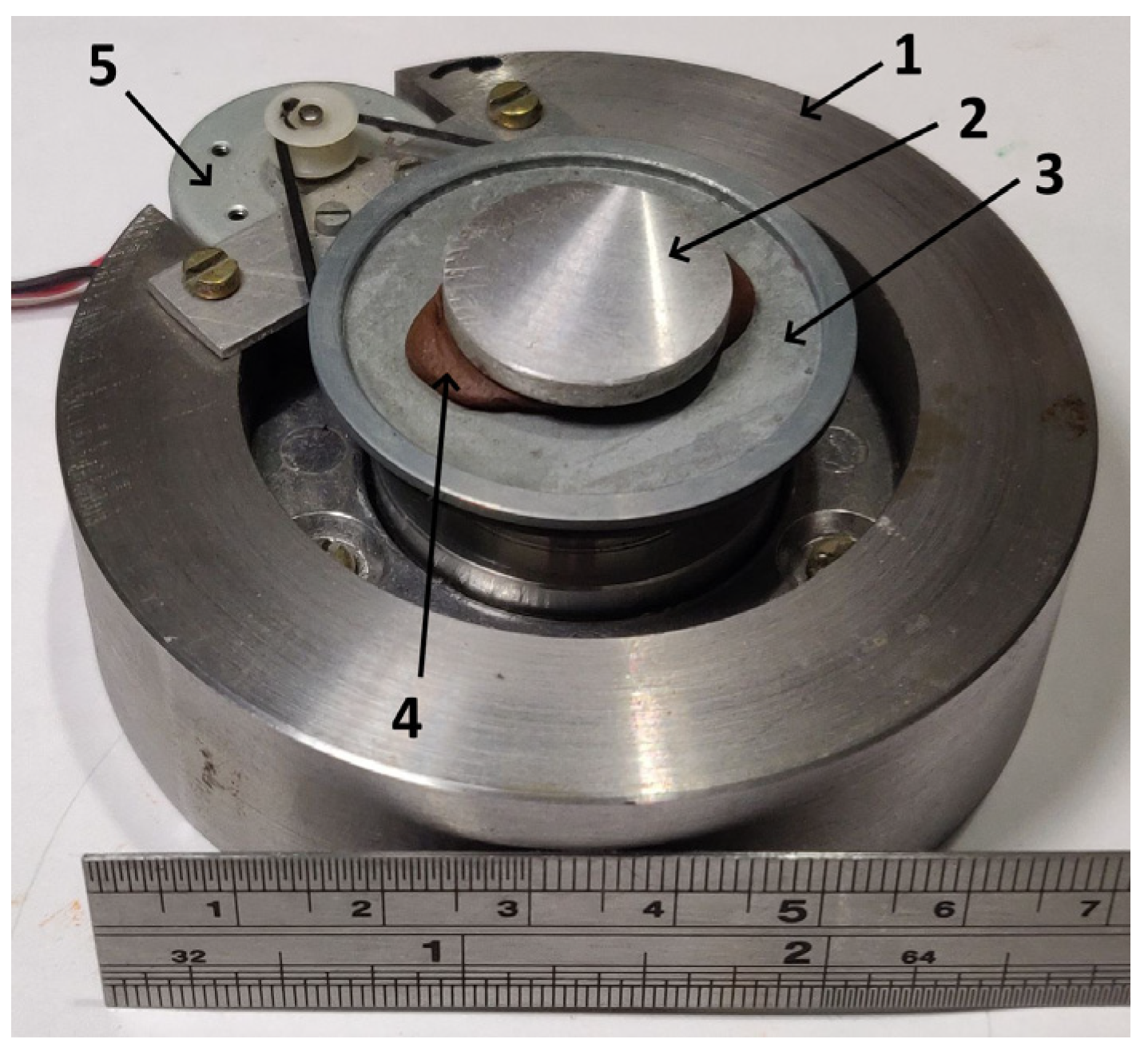
  • A novel approach to microtribological testing on the base of the indentation tester equipped with an additional precision rotational stage is proposed, which could pave the gap between macro- and nanoscale and significantly expand the functionality of the indentation testers.
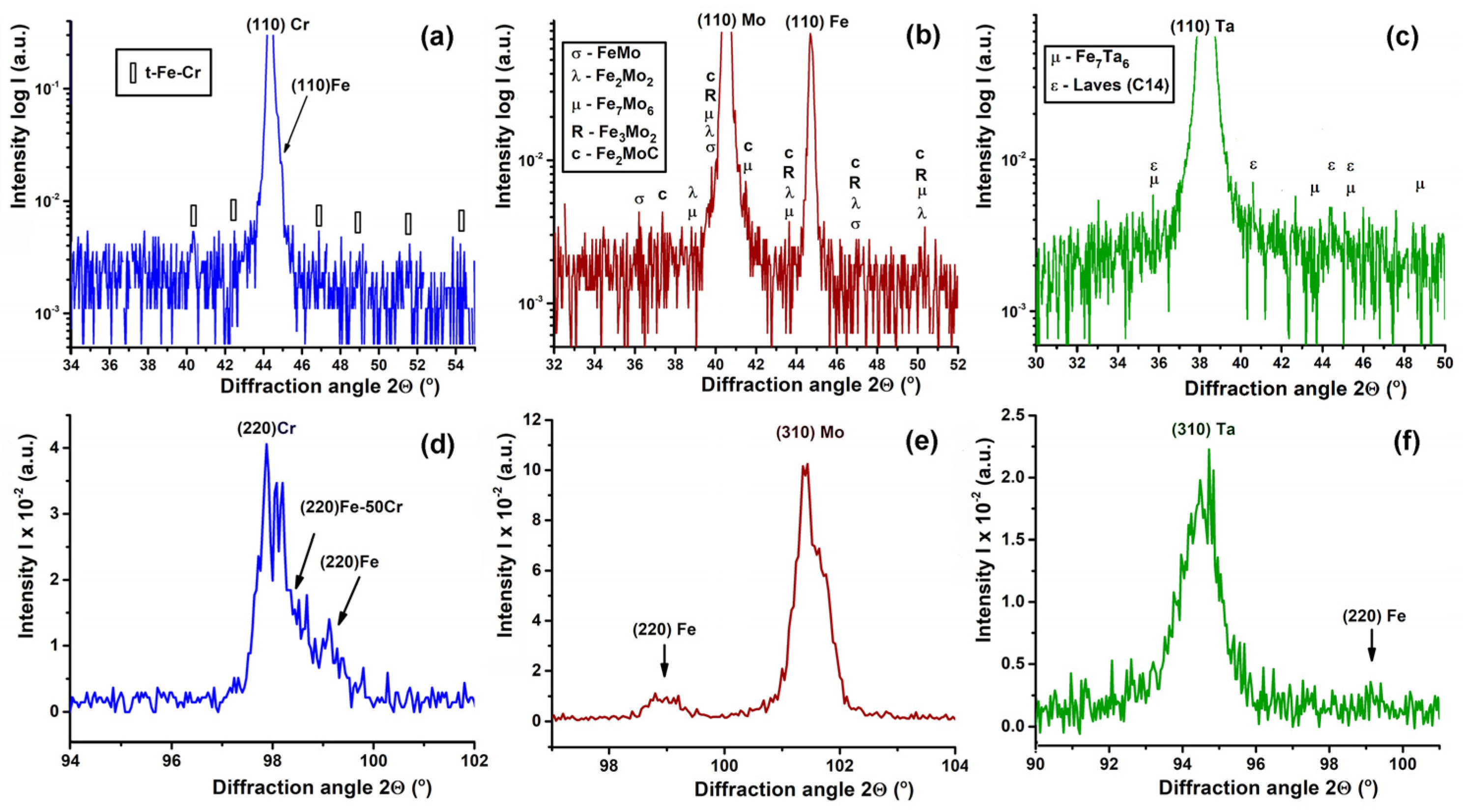
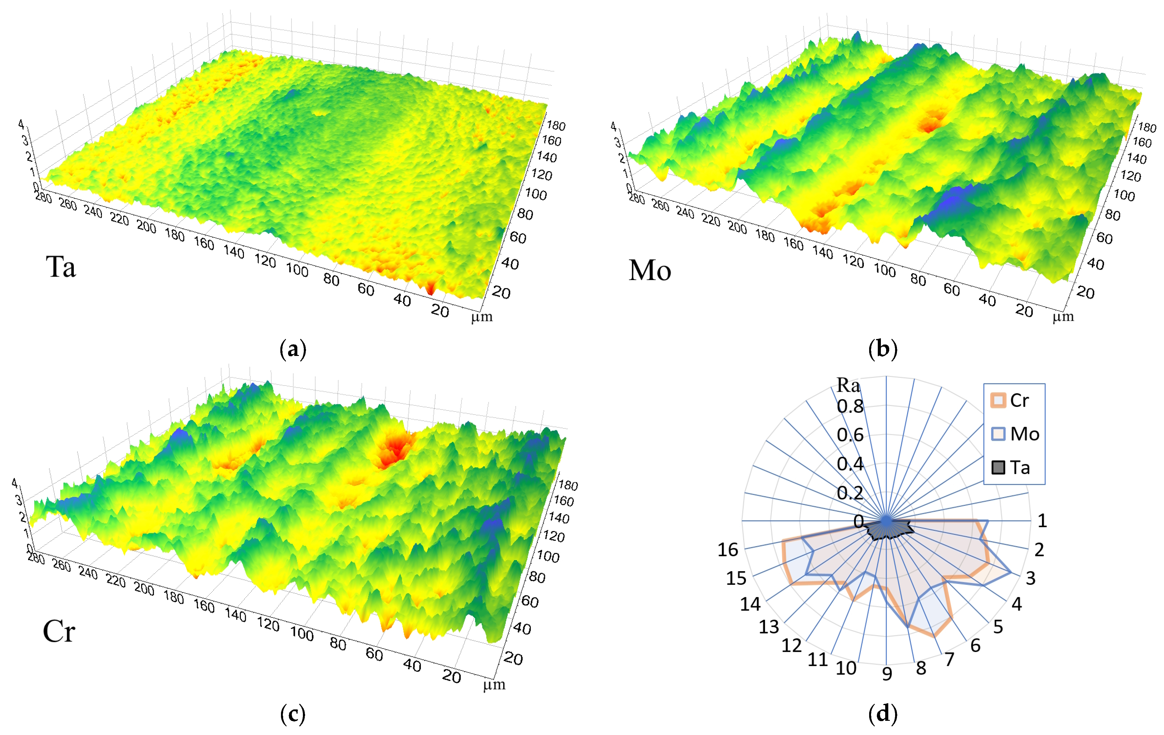
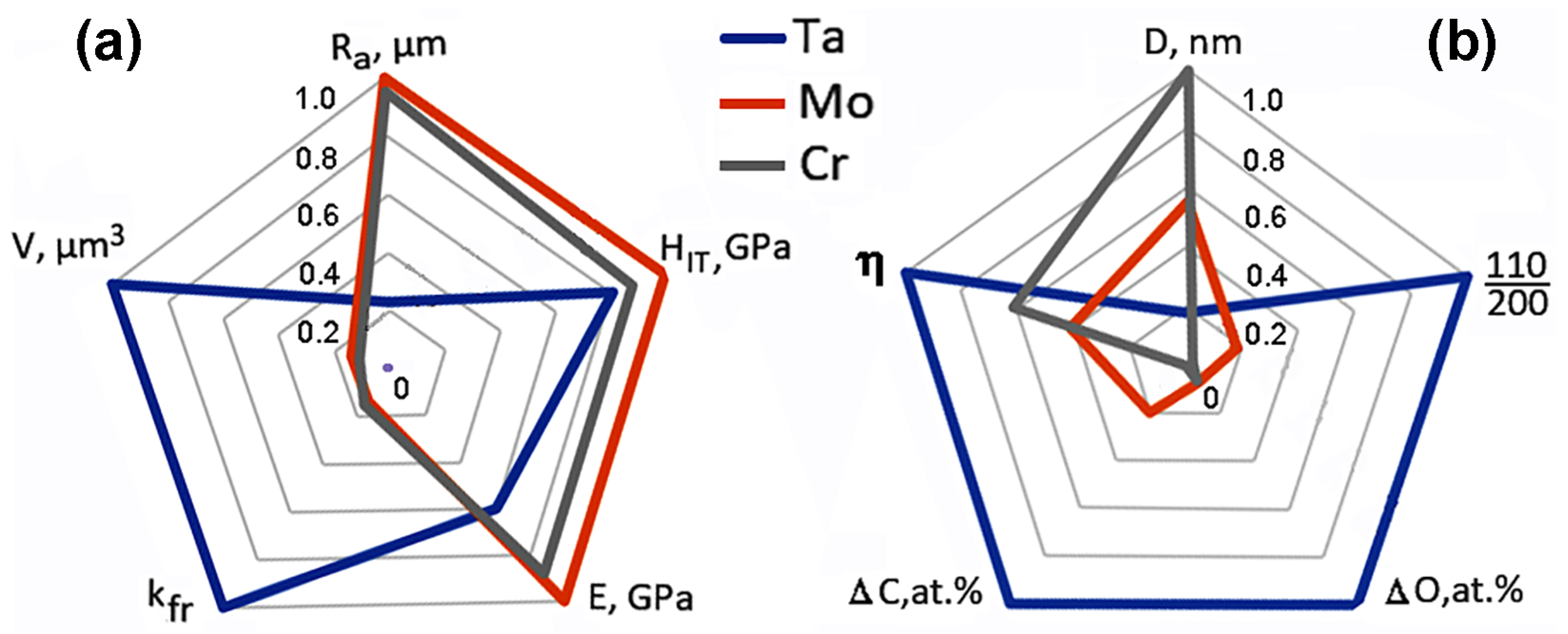
  • The abovementioned methods were used to characterize the chromium, molybdenum, and tantalum coatings produced by vacuum arc deposition. The surfaces of the chromium and molybdenum arc-deposited coatings are observed to be much rougher (maximum values reaching Ra = 0.9 µm) and characterized by a high roughness anisotropy. Conversely, the surface of the tantalum arc-deposited coating is much smoother (Ra = 0.2 µm).
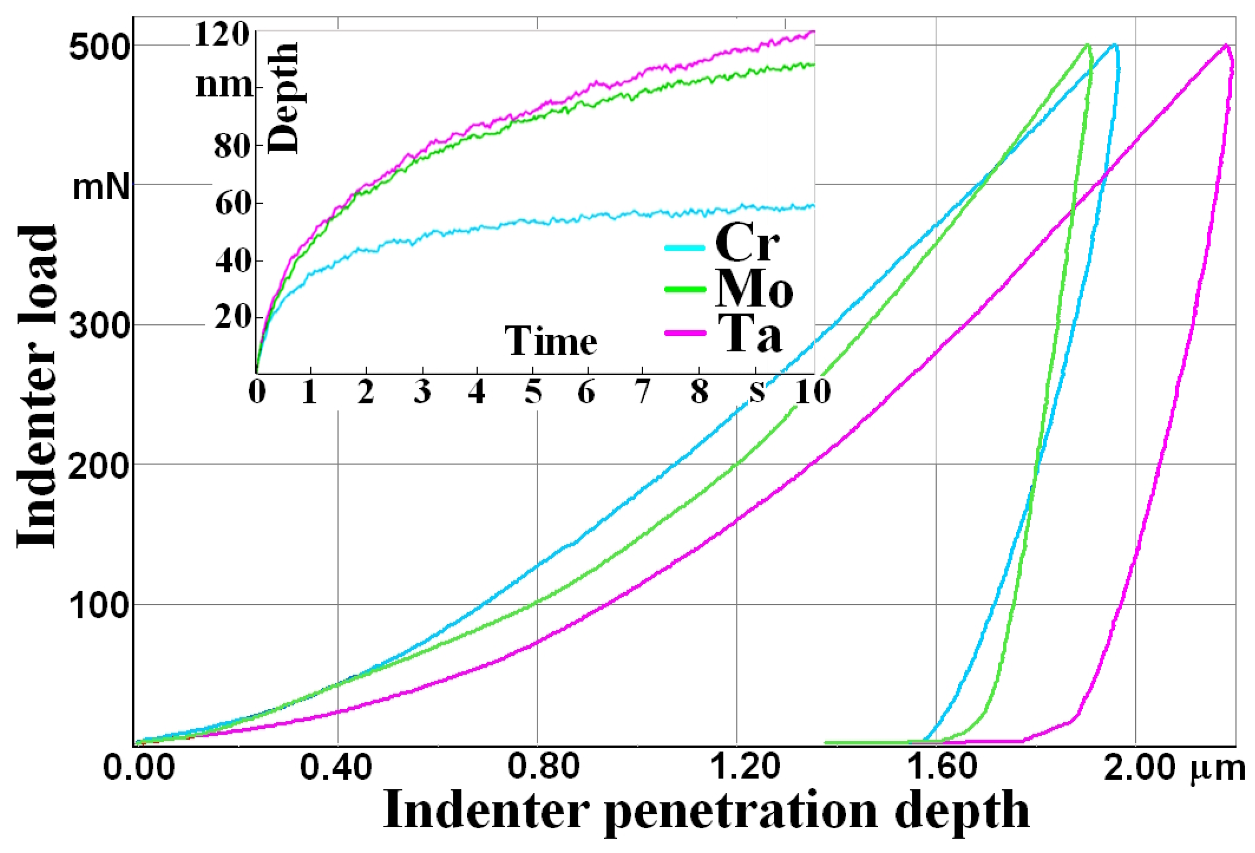
  • As observed, the arc-deposited coatings possess a higher hardness and reduced elastic modulus than the same materials produced by casting. These features relate to the observed formation of nanoscale grains, crystallographic anisotropy, and compressive stresses.
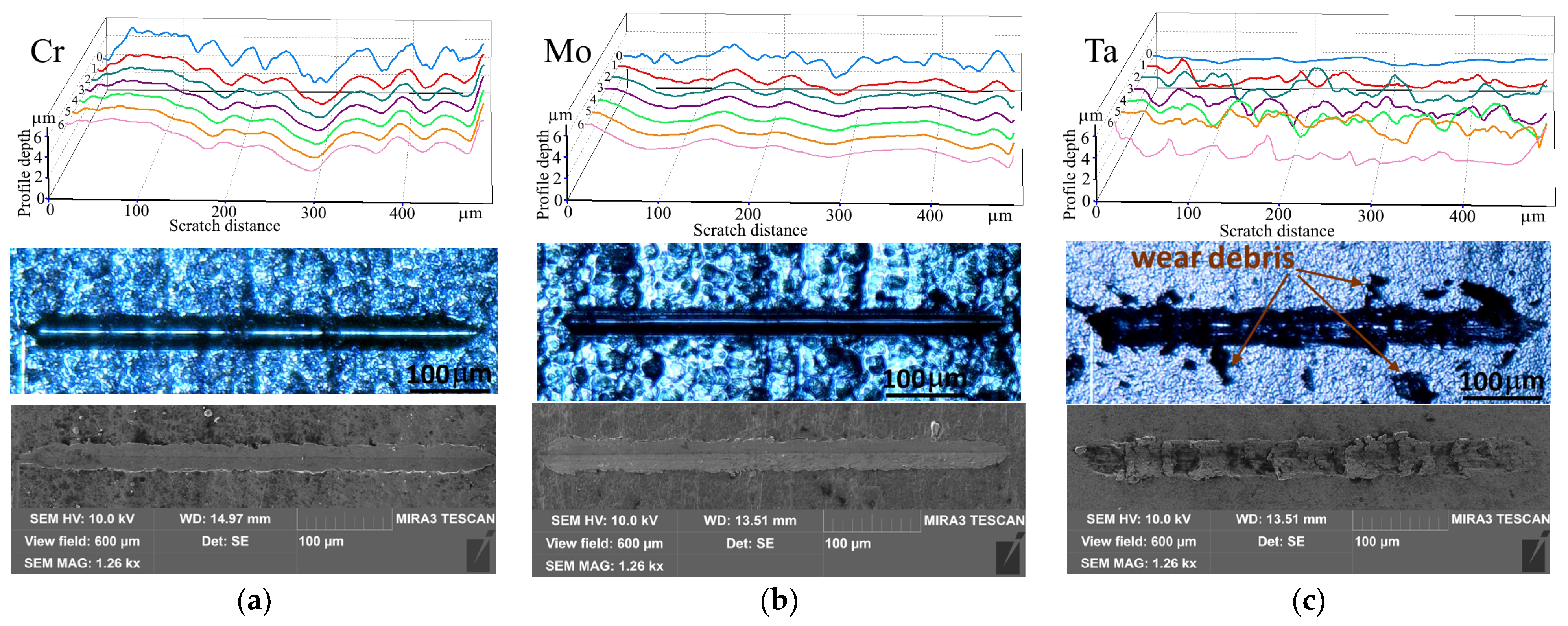
  • Mechanical characterization of deposited coating using depth-sensing indentation and multi-pass scratch tests shows that Mo coating has the highest indentation and scratch hardness (HIt = 4.2 GPa and Hs = 4.3 GPa) and elastic modulus (E = 285 GPa). It has better scratch resistance but lower micro-fatigue resistance and strain-hardening tendency than Cr coating. Ta coating has the lowest values of indentation hardness (HIt = 3.4 GPa) and elastic modulus (E = 171 GPa) and is subjected to severe adhesive wear with material transfer during multi-pass scratch testing despite the lower surface roughness (Ra = 01–02 µm).
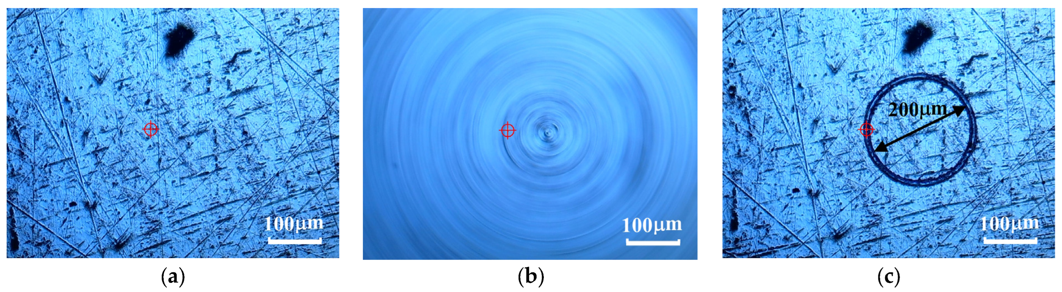
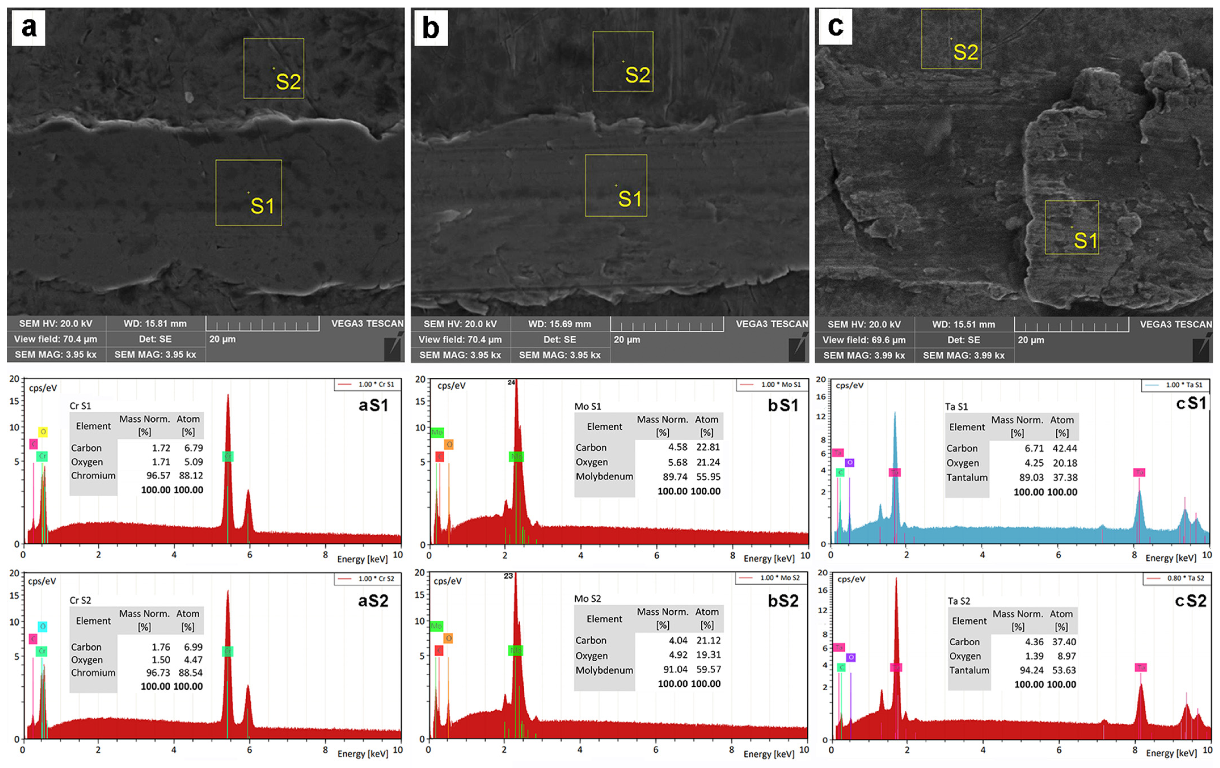
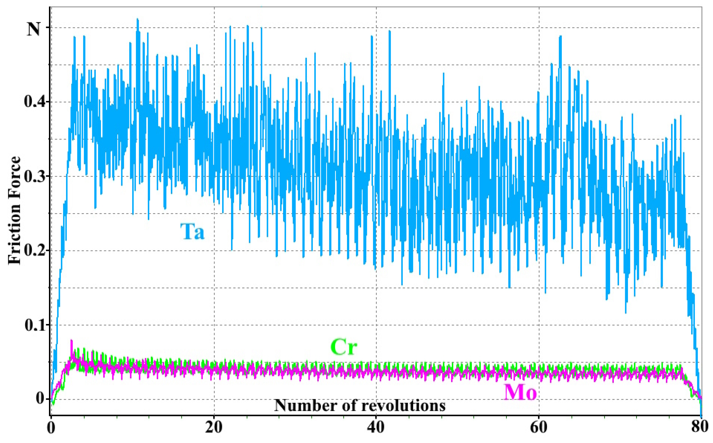
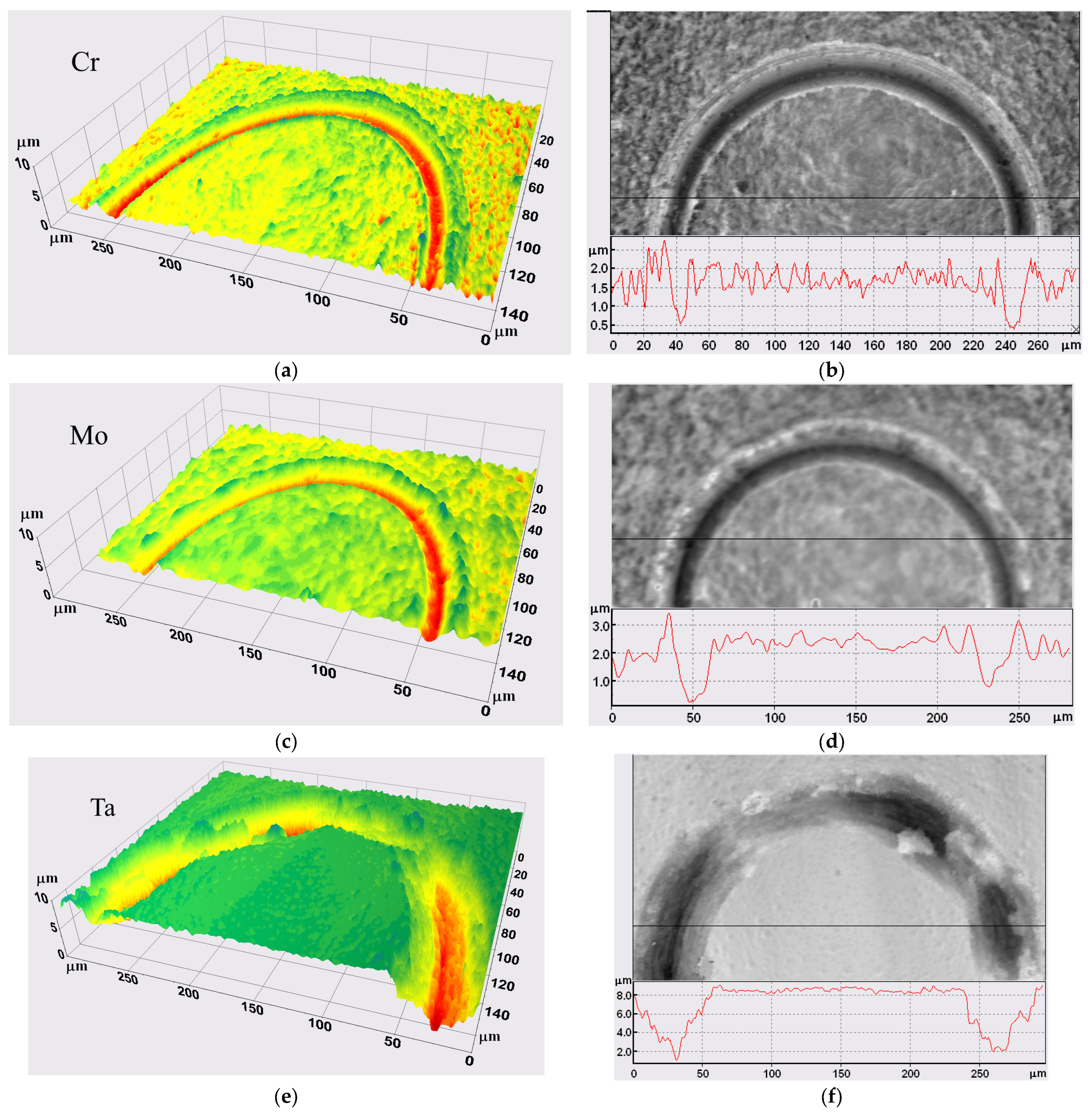
  • The microtribological test of the coatings obtained by vacuum-arc deposition showed different microtribological behavior. The tantalum coating has the lowest wear resistance and highest friction coefficient (0.6) among tested coatings; the volume of worn material is the largest and equal to VTa = 172 × 106 µm3. The surface topography analysis showed adhesive wear of the coating accompanied by sticking and transfer of material along the track path. This is also confirmed by the multi-pass scratch test results; a correlation between the first and further recorded profilograms is absent, and the scratch profiles change dramatically after each pass. This can be explained by the fact that tantalum has a strong adhesive interaction with the indenter material. Coatings from molybdenum and chromium have a low coefficient of friction (kfr = 0.08 and 0.09, respectively) and show a good scratch resistance and wear performance, which are in a good correlation with their mechanical properties.

Author Contributions

Conceptualization, I.Z., V.Z. and V.N.; methodology, I.Z., V.Z. and V.N.; software, O.Y.; validation, V.Z., B.M. and S.Y.; investigation, V.Z., I.Z. and M.S.; resources, V.Z., B.M. and I.T.; writing—original draft preparation, V.Z., I.Z. and B.M.; writing—review and editing, V.Z. and B.M.; visualization, I.Z., V.Z. and O.Y. All authors have read and agreed to the published version of the manuscript.

Funding

This research received no external funding.

Institutional Review Board Statement

Not applicable.

Informed Consent Statement

Not applicable.

Data Availability Statement

Data are contained within the article.

Acknowledgments

The authors are grateful to A.P. Burmak for gathering the XRD data.

Conflicts of Interest

Author V. Nadtoka was employed by the company M. K. Yanhel State Design Bureau “Pivdenne”. The authors remaining declare that the research was conducted in the absence of any commercial or financial relationships that could be construed as a potential conflicts of interest.

References

  1. Klesnil, M.; Lukás, P. Fatigue of Metallic Materials, 2nd ed.; Elsevier: Amsterdam, The Netherlands, 1992. [Google Scholar]
  2. Cooper, D.R.; Skelton, A.C.H.; Moynihan, M.C.; Allwood, J.M. Component level strategies for exploiting the lifespan of steel in products. Resourc. Conserv. Recycl. 2014, 84, 24–34. [Google Scholar] [CrossRef]
  3. Kodur, V.K.; Aziz, E.M.; Naser, M.Z. Strategies for enhancing fire performance of steel bridges. Eng. Struct. 2017, 131, 446–458. [Google Scholar] [CrossRef]
  4. Sun, Y.; Bailey, R. Improvement in tribocorrosion behavior of 304 stainless steel by surface mechanical attrition treatment. Surf. Coat. Technol. 2014, 253, 284–291. [Google Scholar] [CrossRef]
  5. Lu, K.; Lu, J. Nanostructured surface layer on metallic materials induced by surface mechanical attrition treatment. Mater. Sci. Eng. A 2004, 375–377, 38–45. [Google Scholar] [CrossRef]
  6. Gill, A.S.; Kumar, S. Surface alloying of H11 die steel by tungsten using EDM process. Int. J. Adv. Manuf. Technol. 2015, 78, 1585–1593. [Google Scholar] [CrossRef]
  7. Mordyuk, B.N.; Prokopenko, G.I.; Volosevych, P.Y.; Matokhnyuk, L.E.; Byalonovich, A.V.; Popova, T.V. Improved fatigue behavior of low-carbon steel 20GL by applying ultrasonic impact treatment combined with the electric discharge surface alloying. Mater. Sci. Eng. A 2016, 659, 119–129. [Google Scholar] [CrossRef]
  8. Gladczuk, L.; Patel, A.; Paur, C.S.; Sosnowski, M. Tantalum films for protective coatings of steel. Thin Solid Films 2004, 467, 150–157. [Google Scholar] [CrossRef]
  9. Mordyuk, B.N.; Prokopenko, G.I.; Grinkevych, K.E.; Piskun, N.A.; Popova, T.V. Effects of ultrasonic impact treatment combined with the electric discharge surface alloying by molybdenum on the surface related properties of low-carbon steel G21Mn5. Surf. Coat. Technol. 2017, 309, 969–979. [Google Scholar] [CrossRef]
  10. Dittrick, S.; Balla, V.K.; Bose, S.; Bandyopadhyay, A. Wear performance of laser processed tantalum coatings. Mater. Sci. Eng. 2011, 31, 1832–1835. [Google Scholar] [CrossRef]
  11. Kou, Q.; Jin, W.; Ge, C.; Pang, J.; Zhang, J.; Haarberg, G.M.; Xiao, S.; Wang, P. Preparation of molybdenum coatings by molten salt electrodeposition in Na3AlF6-NaF-Al2O3-MoO3 system. Coatings 2023, 13, 1266. [Google Scholar] [CrossRef]
  12. Broitman, E.; Jahagirdar, A.; Rahimi, E.; Meeuwenoord, R.; Mol, J.M.C. Microstructural, nanomechanical, and tribological properties of thin dense chromium coatings. Coatings 2024, 14, 1597. [Google Scholar] [CrossRef]
  13. Moreira, H.; Costa-Barbosa, A.; Marques, S.M.; Sampaio, P.; Carvalho, S. Evaluation of cell activation promoted by tantalum and tantalum oxide coatings deposited by reactive DC magnetron sputtering. Surf. Coat. Technol. 2017, 330, 260–269. [Google Scholar] [CrossRef]
  14. Perepl’otchikov, E.F.; Vasyliv, K.B.; Vynar, V.A.; Zakiev, V.I. Elevation of the Wear Resistance of Low-Alloy Structural Steel by Plasma-Powder Surfacing with Alloys Based on Iron, Chromium, and Nickel. Mater. Sci. 2018, 54, 378–386. [Google Scholar] [CrossRef]
  15. Nascimento, M.P.; Souza, R.C.; Pigatin, W.L.; Voorwald, H.J.C. Effects of surface treatments on the fatigue strength of AISI 4340 aeronautical steel. Int. J. Fatigue 2001, 23, 607–618. [Google Scholar] [CrossRef]
  16. Gao, Y.; Li, X.; Yang, Q.; Yao, M. Influence of surface integrity on fatigue strength of 40CrNi2Si2MoVA steel. Mater. Lett. 2007, 61, 466–469. [Google Scholar] [CrossRef]
  17. Aubert, A.; Gillet, R.; Gaucher, A.; Terrat, J.P. Hard chrome coatings deposited by vapour deposition. Thin Solid Films 1983, 108, 165–172. [Google Scholar] [CrossRef]
  18. Nascimento, M.P.; Souza, R.C.; Miguel, I.M.; Pigatin, W.L.; Voorwald, H.J.C. Effects of tungsten carbide thermal spray coating by HP–HVOF and hard chromium electroplating on AISI 4340 high strength steel. Surf. Coat. Technol. 2001, 138, 113–124. [Google Scholar] [CrossRef]
  19. Michailidis, N.; Stergioudi, F.; Maliaris, G.; Tsouknidas, A. Influence of galvanization on the corrosion fatigue performance of high-strength steel. Surf. Coat. Technol. 2014, 259, 456–464. [Google Scholar] [CrossRef]
  20. Korzynski, M.; Pacana, A.; Cwanek, J. Fatigue strength of chromium coated elements and possibility of its improvement with slide diamond burnishing. Surf. Coat. Technol. 2009, 203, 1670–1676. [Google Scholar] [CrossRef]
  21. Cohen, M.D.; Kargacin, B.; Klein, C.B.; Costa, M. Mechanisms of chromium carcinogenicity and toxicity. Crit. Rev. Toxicol. 1993, 23, 255–281. [Google Scholar] [CrossRef]
  22. Efremenko, V.G.; Lekatou, A.G.; Chabak, Y.G.; Efremenko, B.V.; Petryshynets, I.; Zurnadzhy, V.I.; Emmanouilidou, S.; Vojtko, M. Micromechanical, corrosion and wet sliding wear behaviours of Co-28Cr-6Mo alloy: Wrought vs. LPBF. Mater. Today Commun. 2023, 35, 105936. [Google Scholar] [CrossRef]
  23. Oehlerking, F.; Stawovy, M.T.; Ohm, S.; Imandoust, A. Microstructural characterization and mechanical properties of additively manufactured molybdenum and molybdenum alloys. Int. J. Refract. Met. Hard Mater. 2022, 109, 105971. [Google Scholar] [CrossRef]
  24. Balla, V.K.; Bodhak, S.; Bose, S.; Bandyopadhyay, A. Porous tantalum structures for bone implants: Fabrication, mechanical and in vitro biological properties. Acta Biomater. 2010, 6, 3349–3359. [Google Scholar] [CrossRef] [PubMed]
  25. Dong, C.; Bi, X.L.; Yu, J.G.; Liu, R.; Zhang, Q.X. Microstructural evolution and sintering kinetics during spark plasma sintering of pure tantalum powder. J. Alloys Comp. 2019, 781, 84–92. [Google Scholar] [CrossRef]
  26. Kaserer, L.; Braun, J.; Stajkovic, J.; Leitz, K.-H.; Tabernig, B.; Singer, P.; Letofsky-Papst, I.; Kestler, H.; Leichtfried, G. Fully dense and crack free molybdenum manufactured by selective laser melting through alloying with carbon. Int. J. Refract. Met. Hard Mater. 2019, 84, 105000. [Google Scholar] [CrossRef]
  27. Ma, S.Q.; Zhao, B.; Pan, S.H.; Shen, X.H.; Yin, Y.G. Quantify strengthening and weakening factors in molybdenum fabricated by laser powder bed fusion (LPBF) with a revisit of its oxygen sensitivity. Mater. Sci. Eng. A 2025, 925, 147856. [Google Scholar] [CrossRef]
  28. Coelho, G.C.; Costa Neto, J.G.; Gama, S.; Ribeiro, C.-A. Experimental Study of the Iron-Tantalum Equilibrium Diagram. J. Phase Equilibria 1995, 16, 121–128. [Google Scholar] [CrossRef]
  29. Ding, N.; Wang, T.L.; Tai, K.P.; Li, J.H.; He, X.; Dai, Y.; Liu, B.X. Structural phase transition in the Fe–Ta system studied by ion beam mixing. J. Alloys Compd. 2009, 476, 253–256. [Google Scholar] [CrossRef]
  30. Lin, C.; Yang, G.W.; Liu, J.B.; Liu, B.X. Metastable crystalline phases formed in the Fe–Ta system by solid-state reaction. J. Alloys Compd. 1999, 288, 159–163. [Google Scholar] [CrossRef]
  31. Guillermet, A.F. The Fe-Mo (Iron-Molybdenum) System. Bull. Alloy Phase Diagr. 1982, 3, 359–367. [Google Scholar] [CrossRef]
  32. Higashi, K.; Fukushima, H.; Sakaguchi, S. Phase structure of electrodeposited Fe-Mo Alloys from aqueous solution. Nippon Tungsten Rev. 1977, 10, 74–82. [Google Scholar]
  33. Dutta Majumdar, J.; Manna, I. Laser surface alloying of AISI 304-stainless steel with molybdenum for improvement in pitting and erosion–corrosion resistance. Mater. Sci. Eng. A 1999, 267, 50–59. [Google Scholar] [CrossRef]
  34. Murakami, T.; Sasaki, S. Microstructure and tribological properties of Fe-Mo alloy-coated steel specimens prepared by low-pressure plasma spraying. Intermetallics 2011, 19, 1873–1877. [Google Scholar] [CrossRef]
  35. Li, Z.G.; Su, Y.N.; Liu, X.P.; Xu, Z. Determination of diffusivity on W and Mo in double glow discharge. Acta Met. Sinica 1995, 8, 145–148. [Google Scholar]
  36. Wang, X.H.; Han, F.; Liu, X.M.; Qu, S.Y.; Zou, Z.D. Effect of molybdenum on the microstructure and wear resistance of Fe-based hardfacing coatings. Mater. Sci. Eng. A 2008, 489, 193–200. [Google Scholar] [CrossRef]
  37. Murakami, T.; Kaneda, K.; Nakano, M.; Xia, Y.; Sasaki, S. Tribological properties of Fe7Mo6-based-alloy lubricated with poly-alpha-olefin containing PN additive. Tribol. Int. 2010, 43, 312–319. [Google Scholar] [CrossRef]
  38. Murakami, T.; Mano, H.; Hibi, Y.; Sasaki, S. Friction and wear properties of Fe7Mo6-based alloy in ethyl alcohol. Tribol. Int. 2010, 43, 2183–2189. [Google Scholar] [CrossRef]
  39. Martin, P.J.; Bendavid, A. Review of the filtered vacuum arc process and materials deposition. Thin Solid Films 2001, 394, 1–14. [Google Scholar] [CrossRef]
  40. Turley, D.M. Erosion of a chromium-plated tank gun barrel. Wear 1989, 131, 135–150. [Google Scholar] [CrossRef]
  41. Mattox, D.M. Handbook of Physical Vapor Deposition (PVD) Processing, 2nd ed.; Elsevier: Amsterdam, The Netherlands, 2010; 944p. [Google Scholar]
  42. Efremenko, B.V.; Shimizu, K.; Espallargas, N.; Efremenko, V.G.; Kusumoto, K.; Chabak, Y.G.; Belik, A.G.; Chigarev, V.V.; Zurnadzhy, V.I. High-temperature solid particle erosion of Cr–Ni–Fe–C arc cladded coatings. Wear 2020, 460–461, 203439. [Google Scholar] [CrossRef]
  43. Lozynskyi, V.; Trembach, B.; Hossain, M.M.; Kabir, M.H.; Silchenko, Y.; Krbata, M.; Sadovyi, K.; Kolomiitse, O.; Ropyak, L. Prediction of phase composition and mechanical properties Fe–Cr–C–B–Ti–Cu hardfacing alloys: Modeling and experimental Validations. Heliyon 2024, 10, e25199. [Google Scholar] [CrossRef] [PubMed]
  44. Holmberg, K.; Matthews, A. Coating Tribology: Properties, Mechanisms, Techniques and Applications in Surface Engineering; Tribology and Interface Engineering Series; Elsevier: Amsterdam, The Netherlands, 2009; 576p. [Google Scholar]
  45. Efremenko, V.G.; Chabak, Y.G.; Fedun, V.I.; Shimizu, K.; Pastukhova, T.V.; Petryshynets, I.; Zusin, A.M.; Kudinova, E.V.; Efremenko, B.V. Formation mechanism, microstructural features and dry-sliding behaviour of “Bronze/WC carbide” composite synthesised by atmospheric pulsed-plasma deposition. Vacuum 2021, 185, 110031. [Google Scholar] [CrossRef]
  46. Beake, B.D.; Harris, A.J.; Liskiewicz, T.W. Review of recent progress in nanoscratch testing. Tribol.-Mater. Surf. Interfaces 2013, 7, 87–96. [Google Scholar] [CrossRef]
  47. Velkavrh, I.; Lüchinger, M.; Kern, K.; Klien, S.; Ausserer, F.; Voyer, J.; Diem, A.; Schreiner, M.; Tillmann, W. Using a standard pin-on-disc tribometer to analyse friction in a metal forming process. Tribol. Int. 2017, 114, 418–428. [Google Scholar] [CrossRef]
  48. Randall, N.X. The current state-of-the-art in scratch testing of coated systems. Surf. Coat. Technol. 2019, 380, 125092. [Google Scholar] [CrossRef]
  49. Taylor, A. X-Ray Metallography; John Wiley & Sons: New York, NY, USA; London, UK, 1964. [Google Scholar]
  50. Lindforfs, P.A.; Mularie, W.M.; Wehner, G.K. Cathodic arc deposition technology. Surf. Coat. Technol. 1987, 29, 275–290. [Google Scholar] [CrossRef]
  51. Vasylyev, M.A.; Mordyuk, B.N.; Sidorenko, S.I.; Voloshko, S.M.; Burmak, A.P.; Kruhlov, I.O.; Zakiev, V.I. Characterization of ZrN coating low-temperature deposited on the preliminary Ar+ ions treated 2024 Al-alloy. Surf. Coat. Technol. 2019, 361, 414–424. [Google Scholar] [CrossRef]
  52. Zakiev, I.; Gogotsi, G.A.; Storchak, M.; Zakiev, V. Glass Fracture during Micro-Scratching. Surfaces 2020, 3, 211–224. [Google Scholar] [CrossRef]
  53. Zakiev, I.; Storchak, M.; Gogotsi, G.A.; Zakiev, V.; Kokoieva, Y. Instrumented indentation study of materials edge chipping. Ceram. Int. 2021, 47, 29638–29645. [Google Scholar] [CrossRef]
  54. Storchak, M.; Zakiev, I.; Zakiev, V.; Manokhin, A. Coatings strength evaluation of cutting inserts using advanced multi-pass scratch method. Measurement 2022, 191, 110745. [Google Scholar] [CrossRef]
  55. Firstov, S.A.; Ignatovich, S.R.; Zakiev, I.M. Size effect in the micro- and nanoindentation and its compensation with regard for the specific features of initial contact. Strength Mater. 2009, 41, 147–155. [Google Scholar] [CrossRef]
  56. Oliver, W.C.; Pharr, G.M. An improved technique for determining hardness and elastic modulus using load and displacement sensing indentation experiments. Mater. Res. 1992, 7, 1564–1583. [Google Scholar] [CrossRef]
  57. ISO/FDIS 14577-1: 2002; Metallic Materials—Instrumented Indentation Test for Hardness and Materials Parameters. Part 1: Test Method. ISO Central Secretariat: Geneva, Switzerland, 2002.
  58. Huang, R.Z.; Xie, H.Q.; Guo, L.; Cai, X.; Yang, X.J.; Wei, K. High cycle fatigue behavior and strengthening mechanisms of laser powder bed fusion pure tantalum. Int. J. Fatigue 2025, 190, 108624. [Google Scholar] [CrossRef]
  59. Duan, F.H.; Naunheim, Y.; Schuh, C.A.; Li, Y. Breakdown of the Hall-Petch relationship in extremely fine nanograined body-centered cubic Mo alloys. Acta Mater. 2021, 213, 116950. [Google Scholar] [CrossRef]
  60. Darling, K.A.; Hornbuckle, B.C.; Marvel, C.J.; Hammond, V.H.; Solanki, K. Effect of constrained inter-granular regions on the inverse Hall-petch phenomena. Mater. Sci. Eng. A 2023, 875, 145125. [Google Scholar] [CrossRef]
  61. Liu, X.; Aarts, J.M.; Ma, S.; Choi, J.J.E. The Influence of Polishing on the Mechanical Properties of Zirconia—A Systematic Review. Oral 2023, 3, 101–122. [Google Scholar] [CrossRef]
  62. Gorban, V.F.; Zakiev, I.M.; Kurilenko, D.V. Mechanical Characteristics of High-Entropy Alloys and Their Constituent Metals in Friction Conditions at Low Sliding Velocities. Powder Metall Met. Ceram. 2019, 58, 265–269. [Google Scholar] [CrossRef]
  63. Fischer, A.; Dudzinski, W.; Gleising, B.; Stemmer, P. Analyzing Mild- and Ultra-Mild Sliding Wear of Metallic Materials by Transmission Electron Microscopy. In Advanced Analytical Methods in Tribology; Dienwiebel, M., De Barros Bouchet, M.I., Eds.; Microtechnology and MEMS; Springer: Cham, Switzerland, 2018. [Google Scholar] [CrossRef]
  64. Mordyuk, B.N.; Voloshko, S.M.; Zakiev, V.I.; Burmak, A.P.; Skoryk, M.A.; Mohylko, V.V.; Khripta, N.I.; Malinin, V.Y.; Lesyk, D.A. Wear and Friction Performance of Alumina-Reinforced Composite Coating on Ti-6Al-4V Alloy Produced by Combining Ultrasonic Impact Treatment and Air-Oxidation. J. Mater. Eng. Perform. 2024. [Google Scholar] [CrossRef]
Figure 1. Schematic model of the multi-pass scratch test.
Coatings 15 00358 g001
Figure 2. Independently driven rotational stage for microtribological tasting.
Coatings 15 00358 g002
Figure 3. Microscopic images explaining the principle of indenter positioning: (a) the initial surface of a static sample, (b) the rotating specimen surface, (c) the surface after the test.
Coatings 15 00358 g003
Figure 4. Fragments of XRD patterns of the chromium, molybdenum, and tantalum arc-deposited coatings on the steel substrate.
Coatings 15 00358 g004
Figure 5. Fragments of XRD patterns and phase compositions of the Cr (a,d), Mo (b,e), and Ta (c,f) arc-deposited coatings on the steel substrate.
Coatings 15 00358 g005
Figure 6. Three-dimensional surface topography of arc-deposited coatings: (a) Ta, (b) Mo, (c) Cr, and the circular diagram describing the surface roughness parameters (d).
Coatings 15 00358 g006
Figure 7. Indentation curves and creep curve for Ta, Mo, and Cr coatings.
Coatings 15 00358 g007
Figure 8. Profilograms registered during the multi-pass scratch test (0—initial surface profile, 1–6—scratch profiles after each repeated pass) with microscopic and SEM images of the final scratches on the Cr (a), Mo (b), and Ta (c) coatings.
Coatings 15 00358 g008
Figure 9. Statistical analysis of the multi-pass scratch test results: (a) mean residual scratch depth at each pass; (b) correlation coefficient between the first and subsequent profilograms (c) correlation coefficient between the adjacent profilograms.
Coatings 15 00358 g009
Figure 10. High-magnification view of scratch tracks (ac) on Cr (a), Mo (b), and Ta (c) arc-deposited coatings and EDS spectra gathered from the scratch tracks (aS1, bS1, cS1) and initial coatings (aS2, bS2, cS2) supplemented with assessed chemical compositions (insets in the EDS spectra).
Coatings 15 00358 g010
Figure 11. Friction force recorded during a microtribological test of the Mo, Cr, and Ta coatings.
Coatings 15 00358 g011
Figure 12. Wear tracks formed after the microtribological test of Cr, Mo, and Ta arc-deposited coating surfaces: (a,c,e) 3D topography; (b,d,f) 2D topography.
Coatings 15 00358 g012
Figure 13. Summarized results of the surface roughness Ra and mechanical properties (hardness HIT, elastic modulus E, friction coefficient kfr, and worn volume V) (a), and microstructural and compositional parameters (grain size D, lattice microstrains η, (110)/(200) XRD peaks intensity ratio, and increments of the carbon and oxygen contents) (b) for the arc-deposited Cr, Mo, and Ta coatings. All the shown parameters were normalized on the observed maximal value.
Coatings 15 00358 g013
Table 1. Micromechanical and microtribological properties of deposited coatings.
CoatingHIT, GPaE, GPaHs, GPakfrkplRa, μmr0–6V, µm3
Ta3.4 (2.8)171 (180)-0.6-0.1 ÷ 0.20.14172 × 106
Mo4.2 (3.3)285 (320)4.30.080.110.4 ÷ 0.90.424 × 106
Cr3.7 (2.0)250 (250)3.40.090.2140.45 ÷ 0.80.8519 × 106
Disclaimer/Publisher’s Note: The statements, opinions and data contained in all publications are solely those of the individual author(s) and contributor(s) and not of MDPI and/or the editor(s). MDPI and/or the editor(s) disclaim responsibility for any injury to people or property resulting from any ideas, methods, instructions or products referred to in the content.

