Article

Cold Spray Preparation of High-Performance Anti-Cavitation Copper Coatings on Steel Substrates

1
State Key Laboratory of Featured Metal Materials and Life-Cycle Safety for Composite Structures, School of Mechanical Engineering, Guangxi University, Nanning 530004, China
2
Guangdong Provincial Key Laboratory of Modern Surface Engineering Technology, Guangdong-Hong Kong Joint Laboratory of Modern Surface Engineering Technology, Institute of New Materials, Guangdong Academy of Sciences, Guangzhou 510651, China
3
AECC Harbin DongAn Engine Co., Ltd., Harbin 150066, China
4
School of Materials Science and Engineering, Central South University, Changsha 410083, China
*
Authors to whom correspondence should be addressed.
Coatings 2025, 15(4), 381; https://doi.org/10.3390/coatings15040381
Submission received: 15 February 2025 / Revised: 20 March 2025 / Accepted: 20 March 2025 / Published: 25 March 2025

Abstract

:
Copper and its alloys are widely used in marine environments due to their excellent corrosion resistance and thermal conductivity. Cold spray technology can avoid the thermal damage to the underlying material and is suitable for the manufacturing and repair of parts. In this study, Cu coatings were prepared on 304 stainless steel substrates by high-pressure cold spray technology, and the effects of cold spray parameters on the microstructure, mechanical properties, and cavitation resistance were investigated. The coatings (Cu-N21, Cu-N22, and Cu-He) were prepared using distinct cold spray parameters: Cu-N21 and Cu-N22 employed nitrogen gas at 5 MPa/800 °C with different nozzle geometries, while Cu-He utilized helium gas at 3 MPa/600 °C. The results show that the porosity of the Cu coating prepared by cold spray technology is less than 0.1%. The coating treated with helium gas exhibits a higher bonding strength (81.3 MPa), whereas the coating treated with nitrogen demonstrates greater strain hardening (130–136 HV0.1). XRD results show that no phase change or oxidation occurred for coatings under all cold spraying conditions. After the cavitation test, the mass loss of the Cu coating is significantly less than that of the as-cast copper. The Cu coating surface first develops holes, and with the increase in cavitation time, the hole area begins to increase. However, with prolonged cavitation exposure, the surface of as-cast copper has a large area of holes, and with the increase in cavitation time, the hole growth rate is faster. These observations indicate the cavitation resistance of the Cu coating prepared by cold spray is more than 10 times higher than that of the as-cast copper. This study highlights the potential application of cold spray technology in the preparation of high-performance anti-cavitation copper coatings.

1. Introduction

Cavitation refers to the process of nucleation, growth, and collapse of gases in these areas due to fluctuations in pressure within the liquid, and the impact stresses generated by gas collapse can have a damaging effect on the surface of the overflow components [1,2]. The collapse of cavitation bubbles generates high-pressure microjets and shockwaves, inducing cyclic stresses that lead to material deformation and fatigue failure [3,4]. There are environmental factors and characteristics of the material itself that affect the anti-cavitation of materials. Environmental factors such as temperature, water quality, and hard impurities in water will also affect its anti-cavitation performance [5]. As far as the material itself is concerned, the size and grain size, hardness and elasticity, and surface morphology of the material will also affect its cavitation resistance [6]. The performance of different types of fluid machinery and related components such as turbines, pumps, impellers, control valves, and piping is severely affected due to cavitation. Surface modification is a sustainable and economical way to improve these components; thus, effective solutions to improve the durability of components operating in extreme conditions necessitate the development of advanced coating materials to combat the deleterious effects of cavitation [7].
Thermal spraying techniques, such as high-velocity oxygen-fuel (HVOF) spraying, arc spraying, and plasma spraying, are traditional coating technologies for surface modification [8,9]. However, the high-temperature process induces oxidation and phase transformations, leading to reduced coating toughness, while high porosity makes the coatings prone to crack initiation. Laser cladding technology, characterized by its high thermal input, may cause weakening of the substrate’s heat-affected zone (HAZ) properties and is also associated with high costs and low efficiency. Electroplating produces thin coatings (typically <100 μm) with poor adhesion, making them prone to peeling under impact.
Cold spray (CS) technology has developed rapidly in recent years; its main uses for thin/thick coating deposition, metal surface repair, wear and corrosion protection, and additive manufacturing in aerospace, marine and offshore, petroleum and natural gas, electricity, and automotive industries have received a lot of attention [10,11]. Cold spray uses compressed gas (nitrogen, helium, air, etc.) to pass through a Laval nozzle at a relatively low temperature as an accelerated airflow to drive powder particles (particle size 1~50 μm) at a low-temperature (room temperature to 1000 °C), supersonic speed (300–1200 m/s) to collide with the substrate in a completely solid state, where the particles undergo strong plastic deformation and deposit to form a coating [12,13]. Distinguished from other thermal spray processes, the formation of cold spray deposits mainly relies on the kinetic energy of particles prior to the collision rather than thermal energy, thus preventing common defects such as oxidation, tensile residual stress, and phase transitions during high-temperature deposition [14]. In addition, the high-speed impact during cold spraying causes mechanical bonding between powder particles, while in certain regions, metallurgical bonding occurs. The interior of the coating and the interface between the coating and the substrate are closely bonded, and the bonding strength of the coating is high. Furthermore, due to the compaction effect of the high-speed impact of particles, the porosity of the cold spray coating is much lower than that of the coating prepared by the traditional thermal spray method [15,16,17]. By optimizing the process parameters, cold spray can process coatings with low porosity and thus high cohesive strength [18]. The cold-sprayed coating, owing to its dense structure and high hardness induced by work hardening, effectively mitigates the initiation and propagation of microcracks during cavitation erosion [19]. Additionally, the finer internal grains and higher density of grain boundaries within the coating enhance its resistance to crack extension. Thus, coatings fabricated using cold spray technology exhibit superior cavitation resistance, offering a promising solution for enhancing the durability of components exposed to harsh environments.
As a key propulsion component of a ship, the propeller is susceptible to corrode and cavitate when it rotates at high speed in seawater. Capillary electrophoresis is caused by the nucleation and collapse of bubbles caused by pressure fluctuations in a liquid medium. Collapsing air bubbles impinge on parts as shock waves or microjets, causing mechanical surface deformation and fracture [20,21]. Copper and its alloys are widely used in marine environments such as in the manufacture of pipes, pumps, valves, and ship propellers, due to their excellent resistance to seawater corrosion [22]. In addition, the stacking fault energy of copper and its alloys is low. Under the action of cavitation, the stacking faults inside can prevent the slip of dislocations, so copper and its alloys have anti-cavitation properties [23]. Currently, there has been extensive research on the cavitation erosion resistance of copper-based materials. For example, copper-based glass composite coatings have been fabricated using high-velocity air fuel (HVAF) spraying technology [24]. And copper–nickel alloy cladding layers have been developed through laser cladding technology [25]. Ni doping into the Cu lattice causes lattice distortion, promotes dislocation formation and grain refinement, and thus increases surface hardness. However, studies on the cavitation erosion resistance of cold-sprayed pure Cu coatings remain insufficient. This research fills this gap.
To sum up, in view of the anti-cavitation capability requirements of ship propellers, the high-power ultrasonic waves emitted by an ultrasonic vibration cavitation testing machine can be used in this experiment to simulate the cavitation phenomenon on the surface of a material in a liquid and indirectly simulate the anti-cavitation capability of the material. A pure copper coating was fabricated on a 304 stainless steel substrate using the cold spraying method. The 304 stainless steel was selected as the substrate due to its widespread use in marine components (e.g., valves, pumps) and compatibility with cold-sprayed coatings. By analyzing the weight loss, cavitation depth, and surface morphology of the cold-sprayed copper coating, as well as the cavitation damage of as-cast copper, the differences in their cavitation erosion resistance are investigated. The findings elucidate the cavitation resistance and damage mechanisms of cold-sprayed copper coatings, providing valuable theoretical guidance for enhancing the cavitation resistance of ship propellers through the application of cold-sprayed Cu coatings. The substrate’s cavitation resistance was not tested, as this study focuses on comparing the coating’s performance to as-cast copper, a benchmark material for marine applications. Future work will evaluate coated vs. uncoated 304 steel under cavitation.

2. Materials and Methods
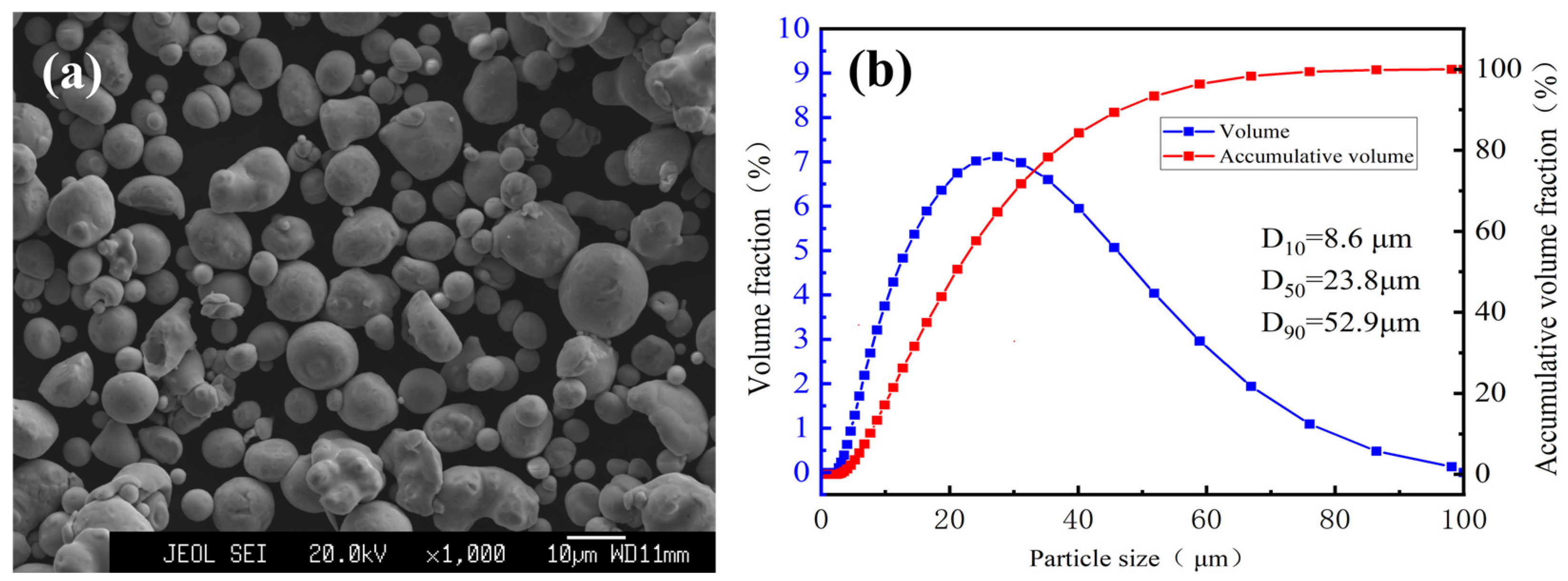
2.1. Materials

In this study, commercially pure Cu powder (Institute of New Materials, Guangdong Academy of Sciences, brand Cu-CS03) was used as the raw material, and its morphology characteristics are shown in Figure 1a. It can be seen that most of the powder is nearly spherical, suggesting good flowability. The particle size distribution (PSD) of the powder is shown in Figure 1b. PSD was measured using a Mastersizer 3000 laser diffraction analyzer (Malvern Panalytical, Malvern, UK). The analysis utilized a wet dispersion method with deionized water as the dispersant. Measurements were performed in triplicate, and the results were averaged to ensure reproducibility. The average particle size D50 of the powder is 23.8 μm, and more than 90% of the particle size is less than 52.9 μm. The shape and PSD of the powder are suitable for the cold spray coating preparation process.
In the cold spray experiments, 304 stainless steel plates with a size of 100 mm × 100 mm and a thickness of 1 mm were selected as the substrate material (199.6 HV0.2). Before cold spray, SiC sandpaper was used to polish the 304 stainless steel substrates to remove the surface oxide film, expose the fresh metal surface, and increase the surface roughness of the substrate, and then an ultrasonic cleaner was used to degrease and clean the substrate with acetone for 10 min. Commercial cast copper (Zhongzhu Machinery Technology Co., Ltd., Cangzhou, China) was used for comparison with copper coating in cavitation erosion experiments.

2.2. Coating Preparation

The cold-sprayed Cu coating was prepared using a PCS-800 high-pressure cold spray system (Plasma Giken, Osaka, Japan). During the cold spray process, nitrogen and helium were used as accelerating gases to prepare copper coatings on 304 stainless steel substrates. The specific cold spray parameters in the experiment are listed in Table 1. The difference between N21 and N22 lies in the nozzle. Due to confidentiality reasons in the laboratory, the details of the nozzles cannot be disclosed. Based on preliminary experimental verification, Nozzle 1 was more suitable for helium spraying.

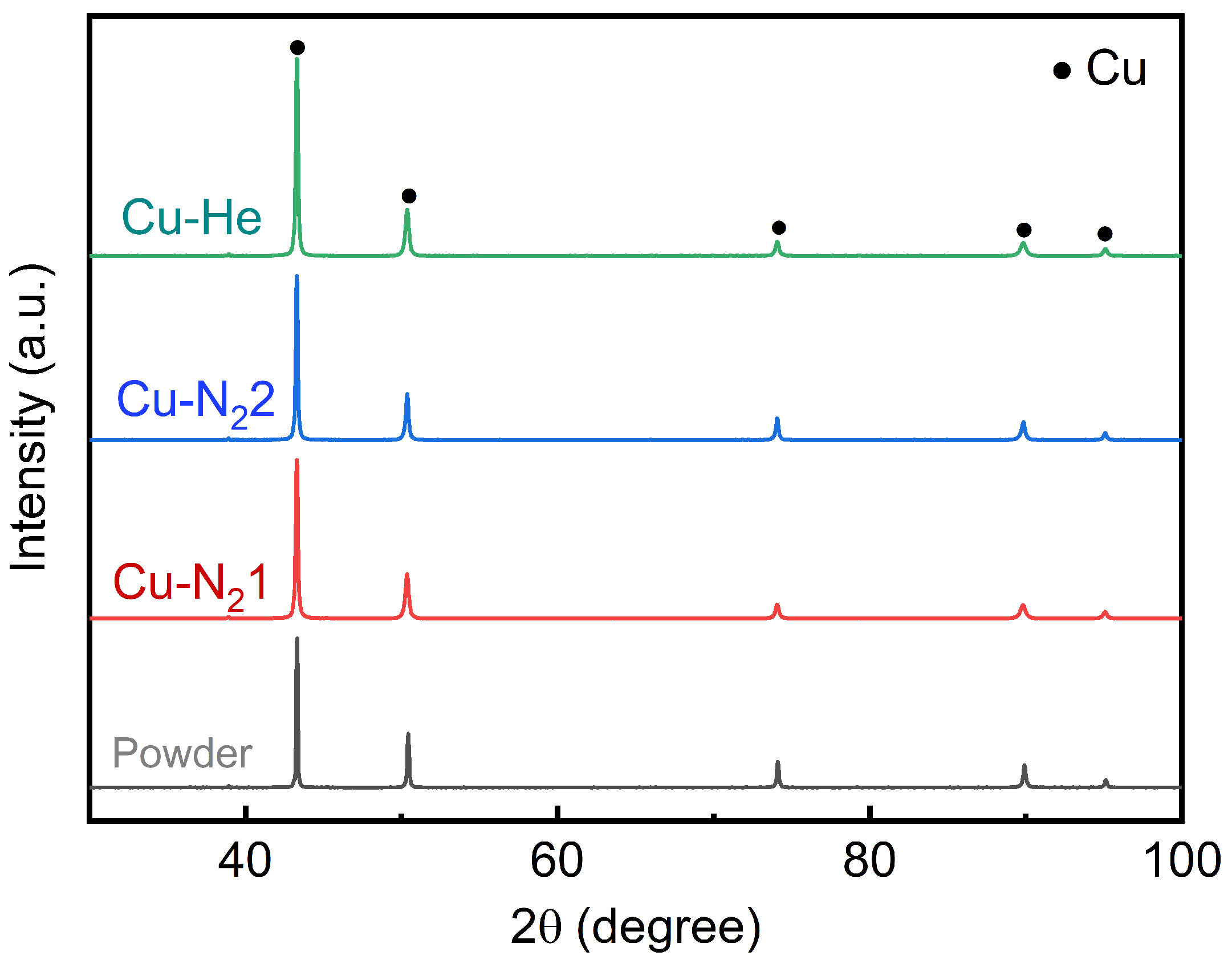
2.3. Microstructure and Phase Analyses

Samples with dimensions of 10 mm × 5 mm × 5 mm were cut by wire cutting for microstructure and phase analyses. The samples were embedded in resin, ground step by step with silicon carbide sandpaper from P600 to P4000, polished through an abrasive slurry, and finally etched with 5 wt.% HCl-FeCl3 solution. The microstructure of the coating cross section was examined using a scanning electron microscope (SEM). The porosity of the coating was quantified using ImageJ software (version 2.1.4.7) on five cross-sectional images (200× magnification). An X-ray diffractometer (XRD, SmartLab III, Rigaku, Tokyo, Japan) was used to analyze the coating phase composition.

2.4. Mechanical Property Tests

The microhardness of the coating was evaluated using a Dura Scan 70G5 Vickers (EMCOTEST, Vienna, Austria) microhardness tester equipped with a diamond pyramid indenter. Measurements were performed under a load of 100 g with a dwell time of 15 s. The average hardness value was determined from 10 randomly selected measurements on the coating surface. The bonding strength of the coating was carried out in accordance with the ASTM C633 standard [26]. The sprayed coating was cut into a disc-shaped sample with a diameter of 25.4 mm, and the coating was glued to the dual tensile piece with FM1000 glue (Solvay, Brussels, Belgium), cured at 190 °C for 5 h, and then cooled to room temperature with a furnace. The prepared samples were put into a universal testing machine model GP-TS2000M (Shenzhen high quality instrument Co., Ltd., Shenzhen, China) for tensile experiments. The GP-TS2000M universal testing machine applied tensile force at 1 mm/min until failure. FM1000 epoxy adhesive (190 °C cure) ensured cohesive failure within the coating or interface.

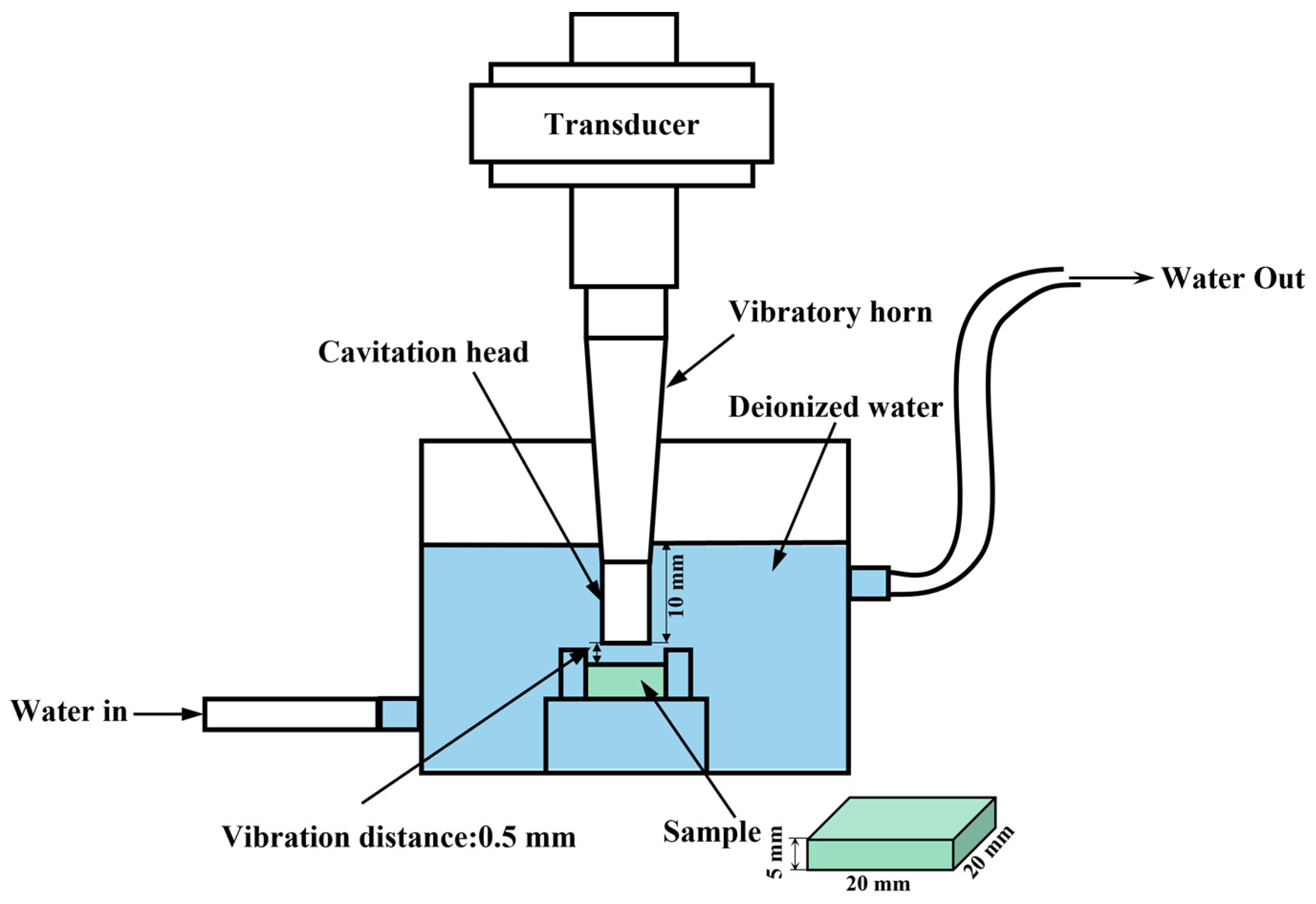
2.5. Cavitation Erosion Test

The cavitation performance of the coating was tested using an XOQS-1000 ultrasonic cavitation testing machine (Nanjing First European Instrument Manufacturing Co., Ltd., Nanjing, China), and the schematic diagram of the device is shown in Figure 2. A frequency of 20 kHz was used for ultrasonic cavitation, the distance of the ultrasonic probe penetrating into the water was 10 mm, and the distance from the cavitation sample was 0.5 mm. This instrument met the ASTM G32 standard [27] and was measured using the fixed sample method [28]. Before the test, the surface of the rectangular (25 mm × 25 mm) samples was polished to Ra < 0.5 µm. The cavitation tests were carried out for 10, 20, and 30 min at a water temperature of 25 °C. The samples after cavitation were dried, and the mass loss of the coating after cavitation was measured with a 0.1 mg precision analytical balance. The morphology changes of the coating after cavitation in different durations were observed by SEM. The surface roughness and 3D profile change in the coating were measured using a 3D profilometer (DEKTAK XT, Bruker Corporation, Billerica, MA, USA).

3. Results and Discussion
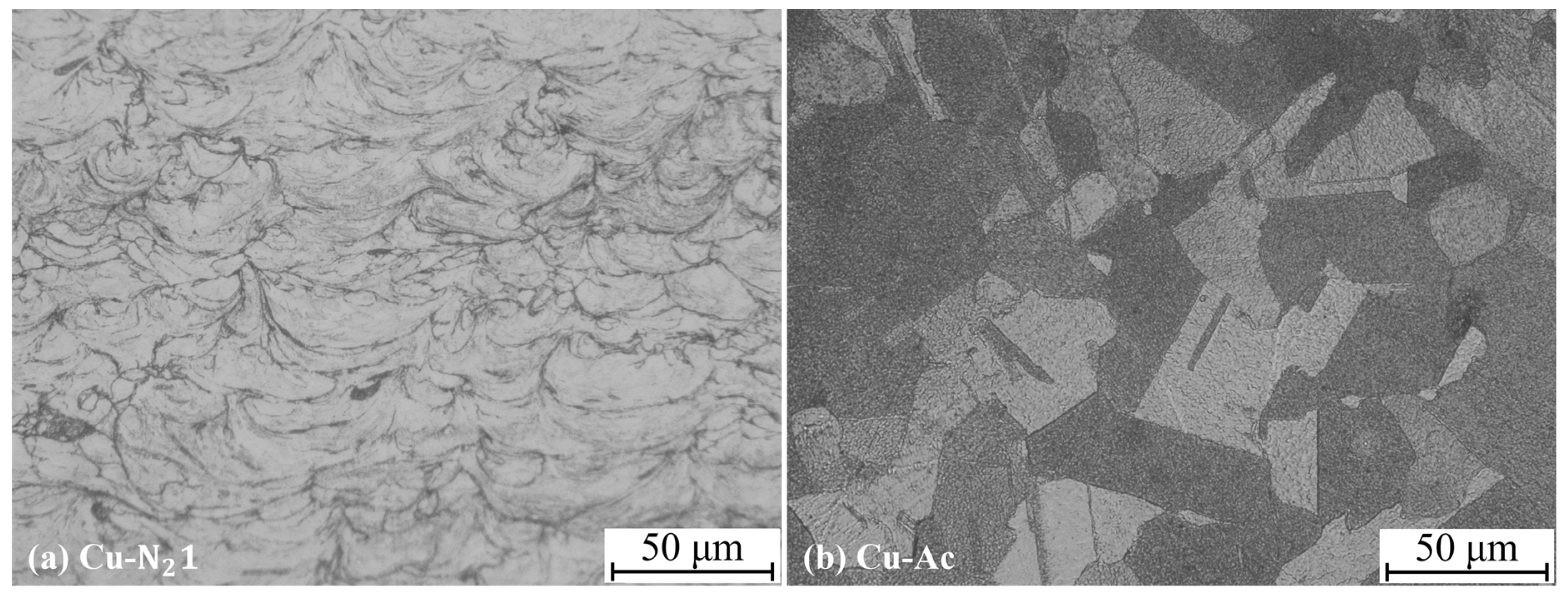
3.1. Microstructure

Figure 3a–c, respectively, show the cross-sectional microstructures of the coatings prepared by cold spray parameters N21, N22, and He. The coating is closely bonded to the substrate, the interior of the coating is dense, and no cracks are found. There are only a few small pores locally, and the porosity is less than 0.1%. The surface of the coating prepared by He is relatively smooth, while the surface of the coating prepared with nitrogen is uneven. Figure 4 shows the XRD results of the copper powder and the sprayed copper coating. The coating retains the original phase of the powder, indicating that there is minimal phase change and that oxidation occurred during cold spray. This indicates the significant benefits of cold spray preparation technology.

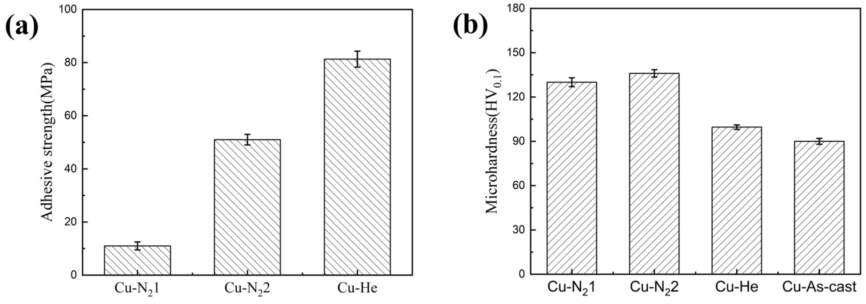
3.2. Mechanical Properties

Figure 5a,b, respectively, show the effects of cold spray parameters on the bonding strength and microhardness of the Cu coating. Figure 5a shows the bonding strengths of the Cu-N21 coating and Cu-N22 coating, respectively, are 11 MPa and 51 MPa, and the failure part is located at the interface between the Cu coating and 304 stainless steel substrate; the bonding strength of the Cu-He coating is 81.3 MPa, and the failure part is between the coating and the colloid interface. The bonding strength of the Cu-He coating is the highest, which is more than seven times higher than that of the Cu-N21 coating. This is because when helium is used as the process gas, its low molecular weight and high specific heat ratio (γ) enable a significant increase in particle velocity during the cold spray process. This increased velocity promotes severe plastic deformation, enhancing interfacial bonding [12]. In terms of hardness, as shown in Figure 5b, the microhardnesses of the Cu-N21 coating, Cu-N22 coating, and Cu-He coating, respectively, are 130 HV0.1, 136 HV0.1, and 99.6 HV0.1. All three coatings are harder than the bulk copper (99.6 HV0.1). This is due to the strong plastic deformation of the powder particles during the cold spraying process, where process hardening occurs [19]. Due to the tamping effect, the internal stresses in the coating increase, resulting in an increase in the hardness of the coating. Lower gas temperature of Cu-He coating reduces thermal softening, resulting in lower hardness. Cold-sprayed Cu coatings exhibit higher hardness than laser cladding Cu-Ni coatings (~110 HV0.1), highlighting cold spray’s superiority for marine applications.

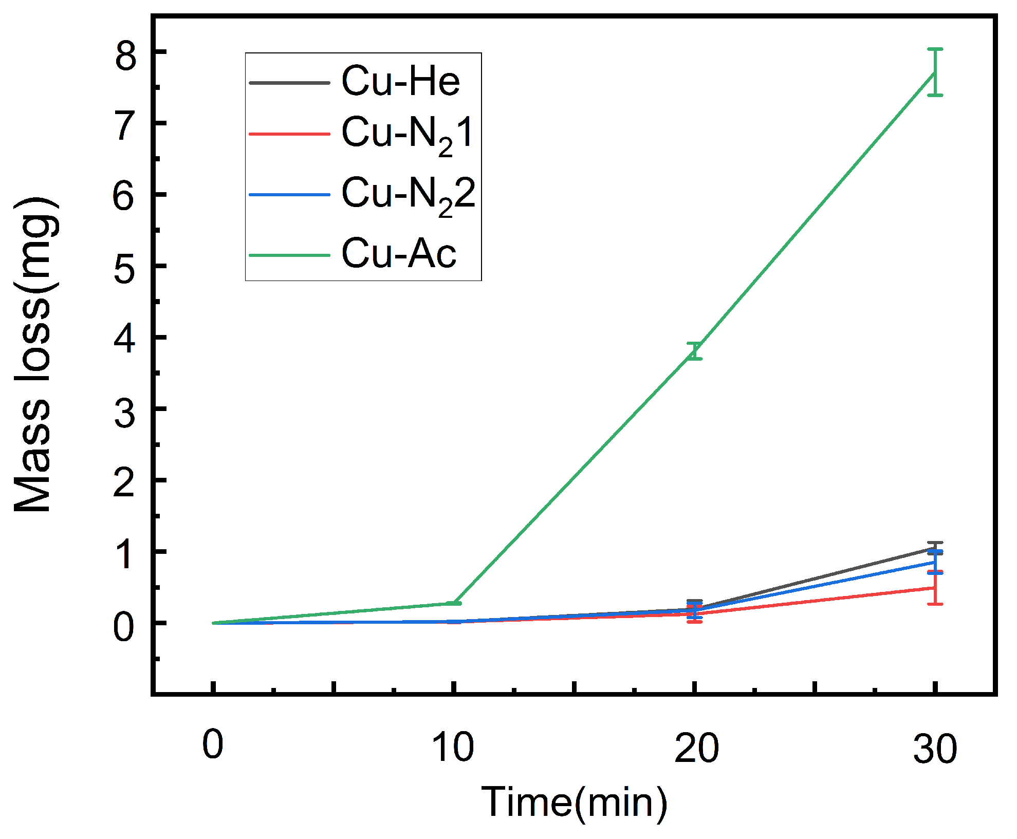
3.3. Influence of Cavitation Time on Coating Weight Loss

Figure 6 is the mass loss versus time curves of the cold-sprayed copper coating and as-cast copper. The mass loss of the four cavitation samples all increases with the prolongation of time. The cavitation mass loss of as-cast copper and the copper coating before 10 min is smaller, and the mass loss of as-cast copper is 0.276 mg. The mass loss of as-cast copper exponentially increases after 10 min, and the mass loss is 3.81 mg. The difference between the copper coating mass loss at 10 min and the mass loss at 20 min is small. After 30 min, the loss of as-cast copper reaches 7.71 mg, which is much higher than the loss of copper coating quality. According to the mass loss, the mass loss per unit time of the as-cast copper is much higher than that of the copper coating, and the cavitation resistance of the cold spray copper coating is more than 10 times higher than that of the as-cast copper substrate.
The mass loss of Cu-N21, Cu-N22, and Cu-He coatings after cavitation damage for 10 min is similar, respectively, at 0.017 mg, 0.019 mg, and 0.02 mg. After 20 min of cavitation damage, the copper coating prepared with nitrogen gas shows more excellent anti-cavitation performance, among which the Cu-N21 coating has the best anti-cavitation performance, and it becomes more obvious with the growth of time.

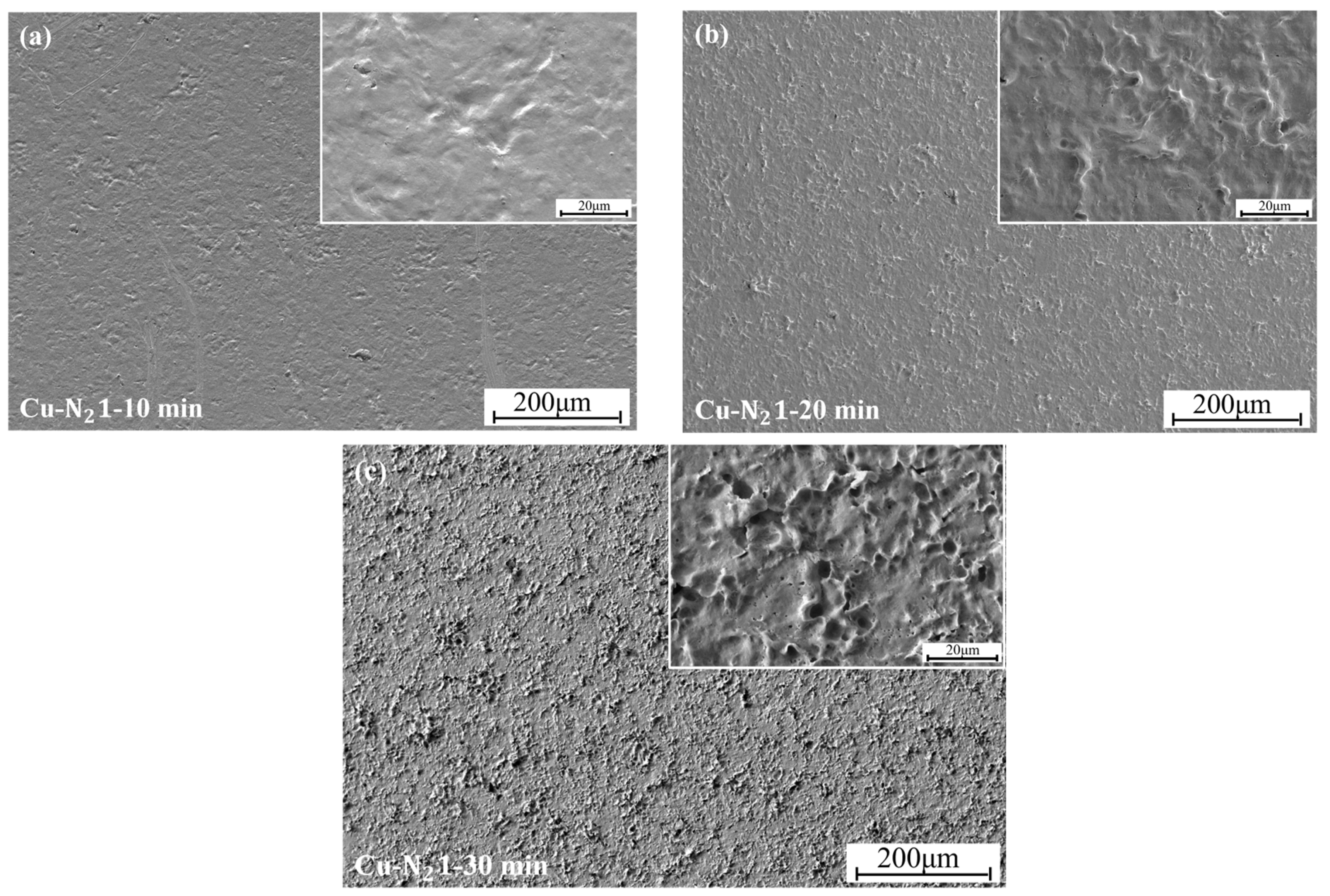
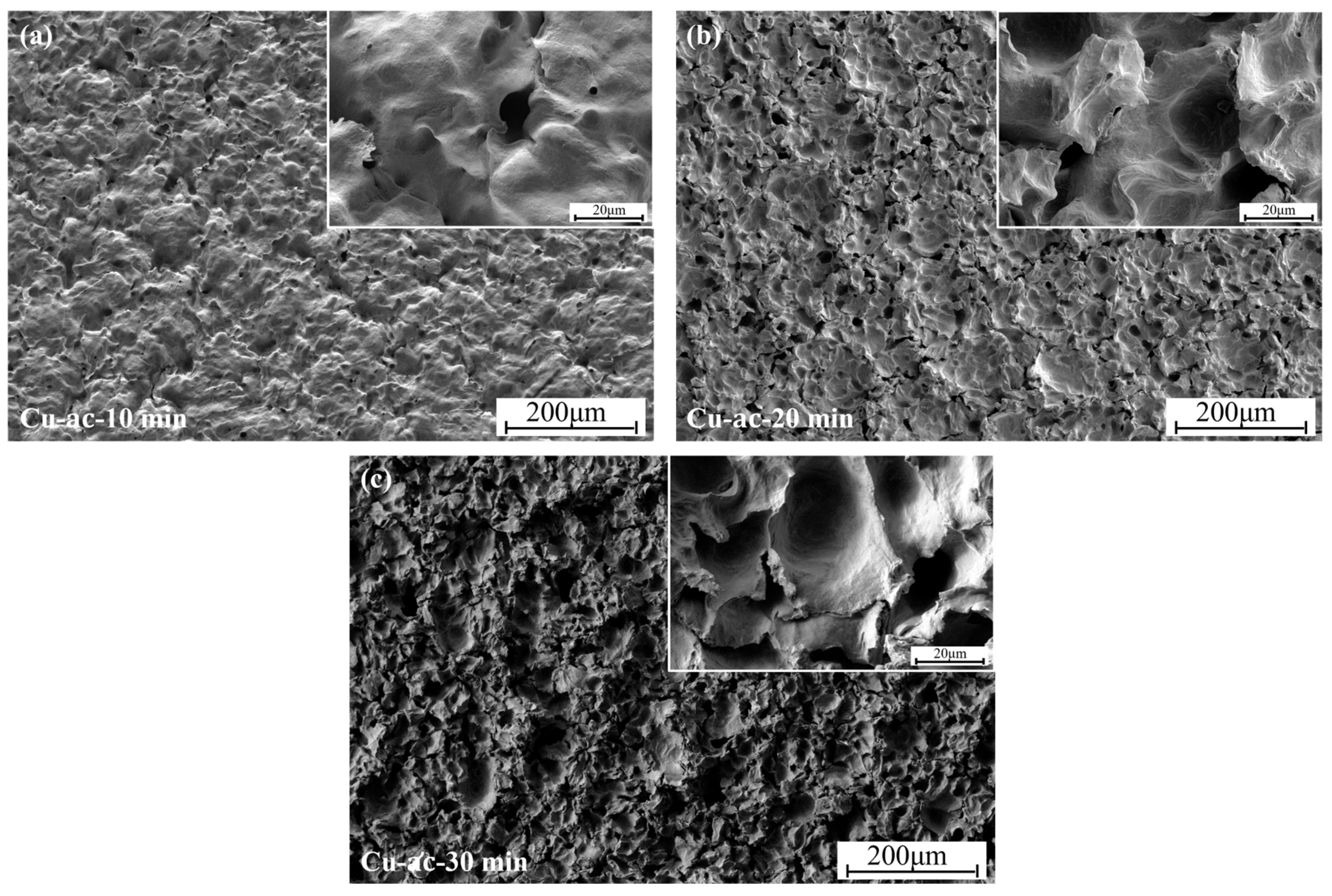
3.4. The Effect of Cavitation on the Microstructure of Coatings

Figure 7a–c, respectively, are SEM images of the surface morphology of the Cu-N21 copper coating after cavitation for 10 min, 20 min, and 30 min. As shown in Figure 7a, after 10 min of cavitation, the surface of the coating shows plastic deformation areas with different areas and shapes, cavitation pits of different sizes and shallow depths are distributed in the deformation areas, and a small number of holes appear in the pits, which are caused by the low cavitation strength [29]. As shown in Figure 7b, when the cavitation time extends to 20 min, the plastic deformation of the coating becomes more serious due to the continuous impact of the microjet during the cavitation process, and “peaks” are formed near the cavitation pits. The depth of the cavitation pits deepens further, with fine cracks appearing in the pits and irregularly shaped holes forming. Figure 7c shows that after 30 min of cavitation, pits of varying sizes are scattered on the surface of the Cu-N21 coating, with the originally smaller pits becoming larger and deeper. A large number of holes exist on the coating surface, which are scattered at the convergence of the cracks. The holes expand in different directions towards the inside of the coating; the prolongation of the cavitation time will destroy the coating in a large area.
Figure 8a–c, respectively, are SEM images of the surface morphology of as-cast copper after cavitation for 10 min, 20 min, and 30 min. As shown in Figure 8a, compared with the morphology of the coating after cavitation, after 10 min of cavitation damage on the as-cast copper, a large range of cavitation pits appears on the surface, and the depth of the cavitation pits is deeper. No pinhole-shaped holes are found, the size of the cavitation pits is relatively uniform, and there are scaly lamellae on the walls of the cavitation pits. Figure 8b show the morphology of as-cast copper after 20 min cavitation. Honeycomb-shaped cavitation pits with small sizes are generated inside the cavitation pit, and layered shedding and hole defects appear on the surface of the pit wall. Figure 8c shows the surface morphology of the as-cast copper cavitation sample after 30 min cavitation. The small-sized cavitation pits are damaged by cavitation, and fracture cracks appear at the junction of the cavitation pit walls. Due to the repeated impact of the cavitation microjets, small holes are formed in the connected area around the pit wall. As the cavitation time increases, the small holes expand, resulting in the thinning of the connected area, which gradually peels off.

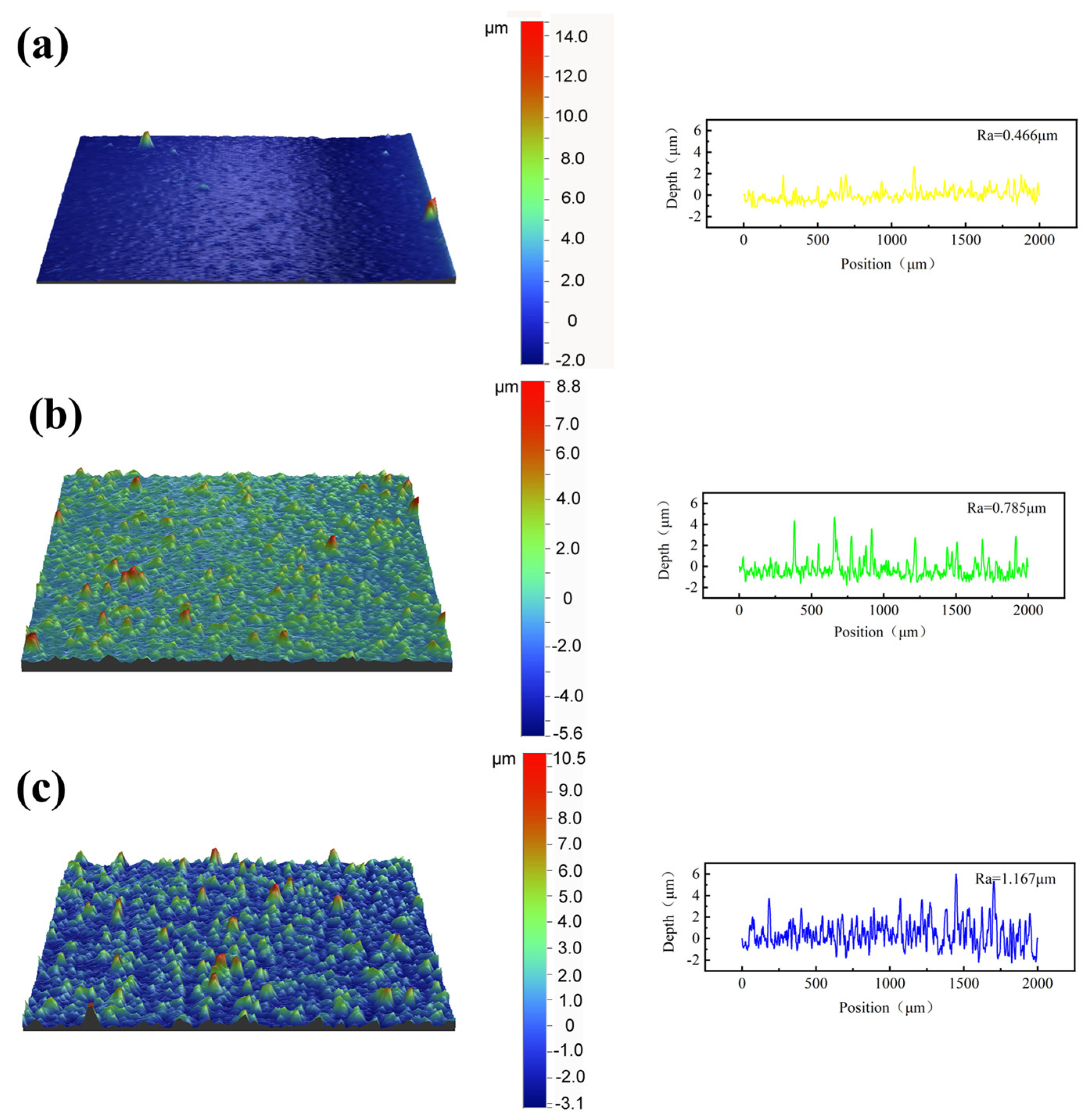
3.5. Three-Dimensional Profile Changes After Coating Cavitation

Figure 9a–c show the 3D profile of the Cu-N21 coating after cavitation failure. The depth of the pit after the coating is damaged by cavitation for 10 min is about 2.14 μm. According to the peak spacing of the 3D profile, as the cavitation time is prolonged, the range of pits becomes smaller, but the number of cavitation pits increases and the depth gradually increases. From the coating surface roughness diagrams at different durations, the roughness Ra of the coating surface after cavitation damage for 10 min, 20 min, and 30 min, respectively, is 0.466 μm, 0.785 μm, and 1.167 μm. The changes in roughness and cavitation rate have different changing rules. The cavitation weight loss analysis shows that the weight loss of the coating is higher in the period of 20 min to 30 min than that in the period of 10 min to 20 min, while the roughness is the opposite. This is because the longer the cavitation time, the more defects on the coating surface due to cavitation, and these defects are more likely to be damaged by the microjets generated by cavitation, causing the coating to fall off and leaving cavitation pits. These cavitation pits may be in different directions inside the coating. The pits inside the coating cannot be scanned by the 3D profiler, but the weighing shows that the weight loss rate of the coating is higher; cavitation also causes the height of the peaks in the 2D profile to be different, so the rate of increase in the 3D profile and the rate of weight loss are not uniform.
Figure 10a–c are 3D contour diagrams of the cavitation damaged cast copper surface. The figure shows that the depth of the pit is about 20.34 μm after 10 min of coating cavitation failure. It can be seen from the figure that the depth of the pit after 10 min of coating cavitation damage is about 20.34 μm. Compared with the cavitation damage morphology of the cold-sprayed copper coating, the depth and area of the as-cast copper pit are larger. This is due to the fact that the as-cast copper grains are larger and are more likely to be damaged by microjets generated by cavitation under the same cavitation conditions. The surface roughness of the coating is analyzed, and the surface roughness Ra of the coating after 10 min, 20 min, and 30 min of cavitation damage, respectively, is 4.95 μm, 8.431 μm, and 10.11 μm, and the change in roughness shows an increasing trend. The reason can be analyzed in conjunction with the 3D profile in Figure 10c, because there are many small pits scattered inside the large pit, which is also consistent with the cavitation surface topography in Figure 8c.

3.6. Cross-Sectional Morphology of Coating After Cavitation

Since cavitation damage may occur inside the coating, which cannot be observed through the surface morphology and 3D contour morphology, the coating cross-section morphology after cavitation is observed. In order to observe the position of cavitation damage more clearly, the cross section of the coating was etched to reveal the interface between the particles in the coating.
The cavitation morphology of the coating cross section of the cavitation sample is shown in Figure 11. By comparing the area of cavitation pits in the cross section of the sample after the cavitation test, it can be analyzed that the coating has better anti-cavitation performance. From the cross-sectional morphology of the Cu-N21 coating and as-cast Cu cavitation in Figure 11, it can be analyzed that there is a certain difference in the annular morphology of the surface cavitation damage between the Cu-N21 coating and as-cast Cu after cavitation damage. For Cu-N21 coatings, cavitation damage first occurs at the particle interface on the coating surface. With the prolongation of cavitation time, cracks appear at the particle interface. Under the damage of cavitation microjet, the cracks extend to the interior of the coating and extend towards the defects between particles, causing the particles inside the coating to detach and causing surface damage to the coating. This is similar to the phenomenon found by Kazasidis et al. [30]. At the same time, it can be seen that many transverse cracks are connected to the corroded surface. In addition, there are large areas of cavitation pits on the surface of the Cu-N21 coating after cavitation damage, and new cracks, holes, and other defects generated after cavitation damage are observed after corrosion. As the cavitation time of cast copper increases, the plastic deformation caused by impact becomes more severe. The accumulation of plastic deformation reaches a certain level, and the energy accumulation reaches saturation, leading to surface burrs like cracks. Under the superposition of cracks, it promotes the large-scale detachment of surface materials. At the same time, many large and deep pits can be observed scattered on the surface of cavitation erosion. This indicates that the surface of the cast Cu is damaged after cavitation, and new defects appear, which are exposed under the action of corrosion. The reason for this difference may be that the hardness of as-cast Cu is lower, and under cavitation damage, the surface undergoes greater plastic deformation, making the interior more susceptible to damage.

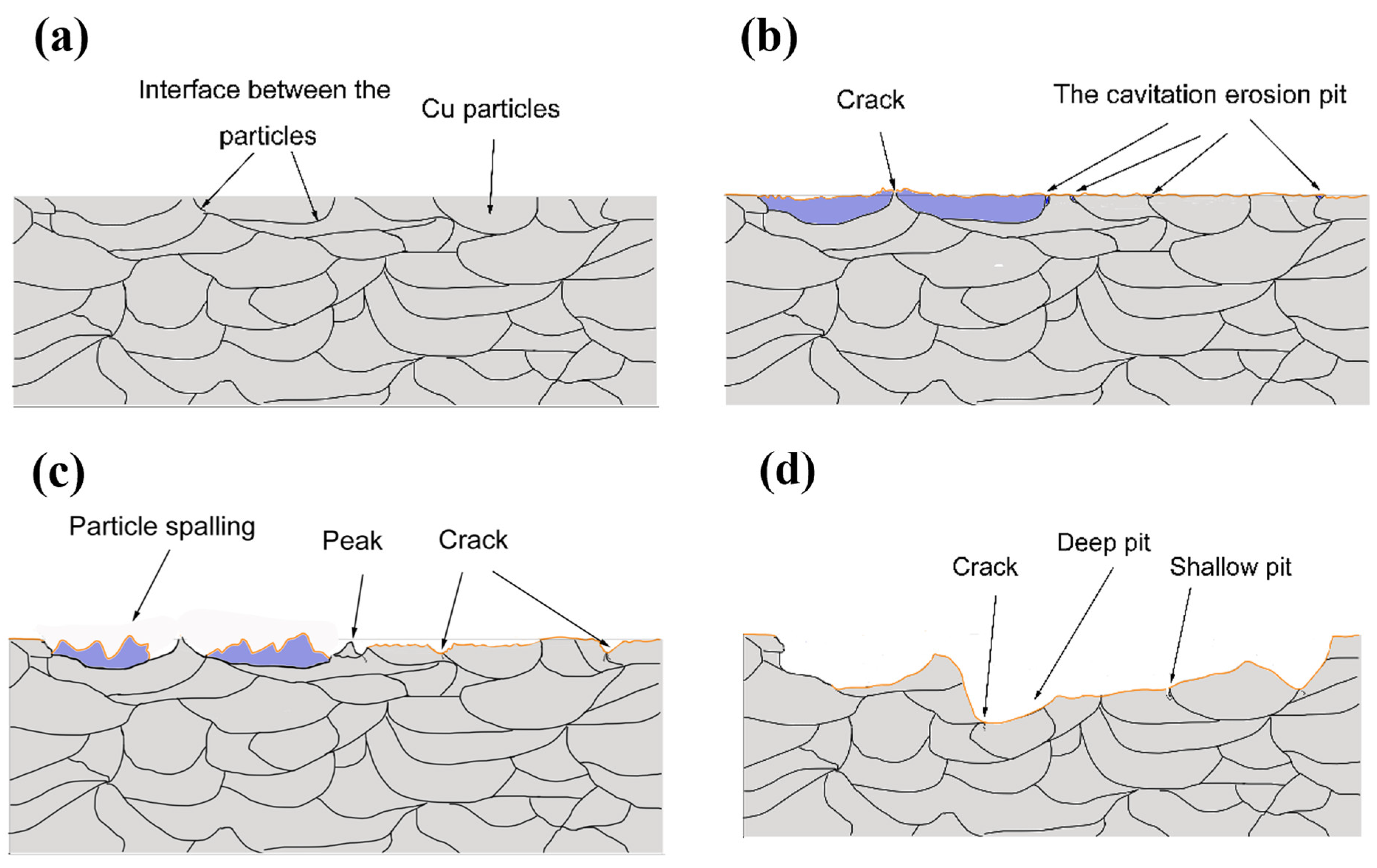
3.7. Analysis of Coating Cavitation Damage Mechanism

Figure 12 displays the etched cross-sectional microstructures of Cu-N21 and Cu-Ac, revealing distinct differences in grain purity between the cold-sprayed Cu coating and the as-cast Cu. Compared to cast copper, the coating exhibits finer internal grains, higher hardness, and a more pronounced work-hardeni ng effect. When subjected to the high stresses of the cavitation process, the increased number of grain boundaries within the coating resists crack propagation. In contrast, in cast copper, coarser internal grain structure and fewer grain boundaries to impede dislocation movement ultimately lead to the phenomenon of large particle spalling [25].
To elucidate the cavitation mechanism of the copper coating, a schematic diagram is provided in Figure 13. Cavitation is through the impact of bubbles, causing dislocations to accumulate at the material–grain interface. When the dislocations accumulate to a certain extent, the high stress field at the grain boundary will cause cracks at the grain boundary, forming a cavitation source [31,32]. Due to the large number of defects at the particle interface inside the coating, cracks preferentially appear at the particle interface of the coating during the cavitation process, and the cracks expand into smaller pores under the action of the cavitation microjet. With the increase in cavitation time, the pores on the surface of the coating gradually become larger, and new cracks appear inside the large erosion pits; the cracks are generated in different directions inside the coating, causing the particles inside the coating to flake off. The cohesion between particles is better, so cavitation damage occurs at the particle boundary and inside the particle at the same time, resulting in cavitation pits and eventually leading to the whole particle falling off. Comparing the coatings prepared with different cold spray parameters, the inner grains of the coating are fine, which can provide more grain boundaries to hinder the movement of dislocations. The resistance to crack propagation inside the coating is relatively large [33], so the cold-sprayed Cu coating shows relatively excellent anti-cavitation performance. However, due to the low hardness and large internal grains of as-cast copper, the cracks expand rapidly inside the material, resulting in serious cavitation damage to the material, and the internal damage becomes more severe as time goes by.

4. Conclusions

In this paper, Cu coatings were deposited on 304 stainless steel substrates with different cold spray parameters (N21, N22 and N2-He) and were subjected to comparative mechanical and cavitation experiments. The relationship between mass loss and time of the cavitation samples as well as the surface topography damaged by different cavitation times were analyzed. The main conclusions are as follows:
(1)
The Cu coating prepared with nitrogen has the best anti-cavitation performance, and the effect is better and more obvious with the prolongation of time, followed by the Cu coating prepared with helium. The cavitation resistance of as-cast Cu is the weakest, and the cavitation resistance of the Cu coating prepared by cold spray after 30 min is more than 10 times higher than that of the as-cast copper.
(2)
Analysis of the coating micromorphology of each group of cavitation samples shows that the degree of damage to the coating surface by cavitation reflects the degree of damage to the material, and the degree of cavitation damage in each time period corresponds to the weight loss curve of the material in the same time period. Therefore, the cavitation resistance of the material can be judged by the damage degree of the microstructure after the material cavitation.
(3)
By comparing the depth of cavitation pits on the cross section of the samples after cavitation, it can be concluded that the cold spray Cu coating has better anti-cavitation performance.

Author Contributions

Conceptualization, Z.S.; methodology, Y.P. and X.C.; data curation, Y.P. and W.L.; writing—original draft preparation, Y.P. and J.M.; writing—review and editing, J.M., X.C. and Y.X.; supervision, C.D. and H.L.; project administration, Y.X.; funding acquisition, Y.X. and X.C. All authors have read and agreed to the published version of the manuscript.

Funding

This work was supported by the National Key R&D Program of China (Grant No. 2023YFE010800, 2022YFB4601601), GDAS’s project of Science and Technology Development (2022GDASZH-2022010203-003), Guangdong Province Science and Technology Plan Projects (2023B1212120008, 2023B1212060045), Key R&D Program of Guangxi Province, China (Grant No. GKAB23026101), Guangxi Natural Science Foundation, China (Grant No. 2023GXNSFBA026287), and Guangzhou Science and Technology Project (2023A04J1626).

Institutional Review Board Statement

Not applicable.

Informed Consent Statement

Not applicable.

Data Availability Statement

Data are contained within the article.

Acknowledgments

The authors are grateful to Yunda Nong, Yuanyuan Liu, and Junfu Peng for the operation of the cold spraying machine. Thanks are also expressed to Jiayan Ma and Zhengwei Qi for their assistance in the experiments.

Conflicts of Interest

Author Zhongwu Sun was employed by the company AECC Harbin DongAn Engine Co., Ltd. The remaining authors declare that the research was conducted in the absence of any commercial or financial relationships that could be construed as a potential conflict of interest.

References

  1. Dular, M.; Bachert, B.; Stoffel, B.; Širok, B. Relationship between cavitation structures and cavitation damage. Wear 2004, 257, 1176–1184. [Google Scholar]
  2. Bajracharya, T.R.; Acharya, B.; Joshi, C.B.; Saini, R.P.; Dahlhaug, O.G. Sand erosion of Pelton turbine nozzles and buckets: A case study of Chilime Hydropower Plant. Wear 2008, 264, 177–184. [Google Scholar] [CrossRef]
  3. Peng, Y.-c.; Chen, X.-y.; Cao, Y.; Hou, G.-x. Numerical Study of Cavitation on the Surface of the Guide Vane in Three Gorges Hydropower Unit. J. Hydrodyn. 2010, 22, 703–708. [Google Scholar]
  4. Chen, F.; Du, J.; Zhou, S. Cavitation erosion behaviour of incoloy alloy 865 in NaCl solution using ultrasonic vibration. J. Alloys Compd. 2020, 831, 154783. [Google Scholar]
  5. Howard, R.L.; Ball, A. The solid particle and cavitation erosion of titanium aluminide intermetallic alloys. Wear 1995, 186, 123–128. [Google Scholar]
  6. Sun, X.; Liu, J.; Ji, L.; Wang, G.; Zhao, S.; Yoon, J.Y.; Chen, S. A review on hydrodynamic cavitation disinfection: The current state of knowledge. Sci. Total. Environ. 2020, 737, 139606. [Google Scholar]
  7. Nair, R.B.; Arora, H.S.; Grewal, H.S. Microwave Synthesized Complex Concentrated Alloy Coatings: Plausible Solution to Cavitation Induced Erosion -Corrosion. Ultrason. Sonochemistry 2018, 50, 114–125. [Google Scholar]
  8. Lakkannavar, V.; Yogesha, K.B.; Prasad, C.D.; Phanden, R.K.; Prasad, S.C. Thermal spray coatings on high-temperature oxidation and corrosion applications—A comprehensive review. Results Surf. Interfaces 2024, 16, 100250. [Google Scholar]
  9. Padmavathi, G.; Sarada, B.N.; Shanmuganathan, S.P.; Padmini, B.V.; Mohan, N. Effects of high velocity oxy fuel thermal spray coating on mechanical and tribological properties of materials—A review. Mater. Today Proc. 2020, 27, 2152–2157. [Google Scholar]
  10. Koivuluoto, H.; Larjo, J.; Marini, D.; Pulci, G.; Marra, F. Cold-Sprayed Al6061 Coatings: Online Spray Monitoring and Influence of Process Parameters on Coating Properties. Coatings 2020, 10, 348. [Google Scholar] [CrossRef]
  11. Sun, W.; Tan, A.W.-Y.; Wu, K.; Yin, S.; Yang, X.; Marinescu, I.; Liu, E. Post-Process Treatments on Supersonic Cold Sprayed Coatings: A Review. Coatings 2020, 10, 123. [Google Scholar] [CrossRef]
  12. Rokni, M.R.; Nutt, S.R.; Widener, C.A.; Champagne, V.K.; Hrabe, R.H. Review of Relationship Between Particle Deformation, Coating Microstructure, and Properties in High-Pressure Cold Spray. J. Therm. Spray Technol. 2017, 26, 1308–1355. [Google Scholar] [CrossRef]
  13. Sun, C.; Gui, W.; Lu, J.; Xie, L.; Wu, Y. Comparison of the Deposition Process for Metallic and MG Coatings Using Cold Spraying. J. Therm. Spray Technol. 2022, 31, 1155–1172. [Google Scholar]
  14. Chen, J.; An, Y.; Liu, G.; Chen, G.; Zhao, X.; Jia, L. Tribological Performance and Thermal Stability of a Novel Cold Sprayed Nanostructured Ni-based Lubrication Coating. J. Therm. Spray Technol. 2022, 31, 1702–1711. [Google Scholar]
  15. Silvello, A.; Cavaliere, P.; Yin, S.; Lupoi, R.; Garcia Cano, I.; Dosta, S. Microstructural, Mechanical and Wear Behavior of HVOF and Cold-Sprayed High-Entropy Alloys (HEAs) Coatings. J. Therm. Spray Technol. 2022, 31, 1184–1206. [Google Scholar]
  16. Nikbakht, R.; Jodoin, B. Thick Cu-hBN Coatings Using Pulsed Gas Dynamic Spray Process: Coating Formation Analysis and Characterization. J. Therm. Spray Technol. 2022, 31, 609–622. [Google Scholar]
  17. Mahaffey, J.; Vackel, A.; Whetten, S.; Melia, M.; Kustas, A.B. Structure Evolution and Corrosion Performance of CoCrFeMnNi High Entropy Alloy Coatings Produced Via Plasma Spray and Cold Spray. J. Therm. Spray Technol. 2022, 31, 1143–1154. [Google Scholar]
  18. Assadi, H.; Schmidt, T.; Richter, H.; Kliemann, J.O.; Binder, K.; Gärtner, F.; Klassen, T.; Kreye, H. On Parameter Selection in Cold Spraying. J. Therm. Spray Technol. 2011, 20, 1161–1176. [Google Scholar]
  19. Zheng, L.; Haché, M.J.R.; Poirier, D.; Legoux, J.G.; Giallonardo, J.D.; Zou, Y.; Howe, J.Y.; Erb, U. Submicrometer scale mapping of microstructure and mechanical properties of cold sprayed copper. Mater. Sci. Eng. A 2025, 920, 147556. [Google Scholar]
  20. Hucińska, J.; Głowack, M. Cavitation Erosion of Copper and Copper-Based Alloys. Metall. Mater. Trans. A 2001, 32, 1325–1333. [Google Scholar]
  21. Shi, Z.-P.; Wang, Z.-B.; Wang, J.-Q.; Qiao, Y.-X.; Chen, H.-N.; Xiong, T.-Y.; Zheng, Y.-G. Effect of Ni Interlayer on Cavitation Erosion Resistance of NiTi Cladding by Tungsten Inert Gas (TIG) Surfacing Process. Acta Metall. Sin. Engl. Lett. 2019, 33, 415–424. [Google Scholar] [CrossRef]
  22. Sun, W.; Chu, X.; Lan, H.; Huang, R.; Huang, J.; Xie, Y.; Huang, J.; Huang, G. Current Implementation Status of Cold Spray Technology: A Short Review. J. Therm. Spray Technol. 2022, 31, 848–865. [Google Scholar] [PubMed]
  23. Zhang, X.F.; Fang, L. The effect of stacking fault energy on the cavitation erosion resistance of alpha-phase aluminum bronzes. Wear 2002, 253, 1105–1110. [Google Scholar] [CrossRef]
  24. Wang, Y.; Wu, Y.; Hong, S.; Cheng, J.; Zhu, S. Cavitation erosion behavior of HVAF-sprayed Cu-based glassy composite coatings in NaCl solution. Intermetallics 2024, 168, 108266. [Google Scholar] [CrossRef]
  25. Chang, Y.; Liu, Z.; Gan, R.; Xiao, H.; Shen, Y. Cavitation erosion characterization of Cu-Ni alloy laser cladding layer under the action of high-pressure water jet. J. Alloys Compd. 2025, 1020, 179325. [Google Scholar] [CrossRef]
  26. Prashar, G.; Vasudev, H. A comprehensive review on the analysis of adhesion strength of cold spray deposits. Results Surf. Interfaces 2024, 16, 100263. [Google Scholar]
  27. Khmelev, V.N.; Barsukov, R.V.; Golykh, R.N.; Abramenko, D.S.; Genne, D.V.; Tertishnikov, P.P. Method and means of cavitation erosion tests under abnormal conditions. J. Phys. Conf. Ser. 2020, 1679, 042041. [Google Scholar] [CrossRef]
  28. Steller, J. International Cavitation Erosion Test and quantitative assessment of material resistance to cavitation. Wear 1999, 233, 51–64. [Google Scholar]
  29. Hong, S.; Wu, Y.; Zhang, J.; Zheng, Y.; Qin, Y.; Lin, J. Ultrasonic cavitation erosion of high-velocity oxygen-fuel (HVOF) sprayed near-nanostructured WC–10Co–4Cr coating in NaCl solution. Ultrason. Sonochem. 2015, 26, 87–92. [Google Scholar] [CrossRef]
  30. Kazasidis, M.; Yin, S.; Cassidy, J.; Volkov-Husović, T.; Vlahović, M.; Martinović, S.; Kyriakopoulou, E.; Lupoi, R. Microstructure and cavitation erosion performance of nickel-Inconel 718 composite coatings produced with cold spray. Surf. Coat. Technol. 2020, 382, 125195. [Google Scholar] [CrossRef]
  31. Wei, Z.; Wu, Y.; Hong, S.; Cheng, J.; Qiao, L.; Cheng, J.; Zhu, S. Ultrasonic cavitation erosion behaviors of high-velocity oxygen-fuel (HVOF) sprayed AlCoCrFeNi high-entropy alloy coating in different solutions. Surf. Coat. Technol. 2021, 409, 126899. [Google Scholar] [CrossRef]
  32. Kanno, A.; Takagi, K.; Arai, M. Influence of chemical composition, grain size, and spray condition on cavitation erosion resistance of high-velocity oxygen fuel thermal-sprayed WC cermet coatings. Surf. Coat. Technol. 2020, 394, 125881. [Google Scholar] [CrossRef]
  33. Cheng, J.; Wu, Y.; Hong, S.; Cheng, J.; Qiao, L.; Wang, Y.; Zhu, S. Cavitation-erosion behavior and mechanism of high-velocity oxygen-fuel sprayed CuAlNiTiSi medium-entropy alloy coating. Surf. Coat. Technol. 2022, 432, 128096. [Google Scholar] [CrossRef]
Figure 1. SEM morphology (a) and particle size distribution (b) of Cu powder.
Coatings 15 00381 g001
Figure 2. Schematic diagram of cavitation experiments.
Coatings 15 00381 g002
Figure 3. Cross-sectional microstructures of cold-sprayed Cu coatings.
Coatings 15 00381 g003
Figure 4. XRD patterns of coating powder and coating.
Coatings 15 00381 g004
Figure 5. Bonding strength (a) and microhardness (b) of coating.
Coatings 15 00381 g005
Figure 6. The relationship between weight loss and time during cavitation.
Coatings 15 00381 g006
Figure 7. SEM cavitation surface morphology of Cu-N21: (a) 10 min, (b) 20 min, (c) 30 min.
Coatings 15 00381 g007
Figure 8. SEM cavitation surface morphology of as-cast copper: (a) 10 min, (b) 20 min, (c) 30 min.
Coatings 15 00381 g008
Figure 9. Two-dimensional/three-dimensional cavitation surface profile of Cu-N21: (a) 10 min, (b) 20 min, (c) 30 min.
Coatings 15 00381 g009
Figure 10. Two-dimensional/three-dimensional cavitation surface profile of as-cast copper: (a) 10 min, (b) 20 min, (c) 30 min.
Coatings 15 00381 g010
Figure 11. SEM morphology of cavitation cross sections of coatings (30 min): (a) Cu-N21, (b) Cu-Ac.
Coatings 15 00381 g011
Figure 12. As-etched cross-sectional microstructures of Cu-N21 and Cu-Ac.
Coatings 15 00381 g012
Figure 13. (ad) Schematic diagram of the cavitation damage mechanism of the cold-sprayed coating.
Coatings 15 00381 g013
Table 1. Process parameters of cold-sprayed Cu coatings.
Gas TypeDenominationNozzle TypeGas Temperature
/°C
Gas Pressure/MPaSpray Distance/mmPowder Feed Rate (g/min)
N2N211800530100
N2N222800530100
HeHe1600330100
Disclaimer/Publisher’s Note: The statements, opinions and data contained in all publications are solely those of the individual author(s) and contributor(s) and not of MDPI and/or the editor(s). MDPI and/or the editor(s) disclaim responsibility for any injury to people or property resulting from any ideas, methods, instructions or products referred to in the content.

