Article

Failure and Damage Analysis of a Polymeric Finish Topcoat on Vinyl Coated Fabrics for Marine Applications

by
Mauricio Acelas
1,
Cristina Combariza
1,
Natalia Trinidad Zapata-Gallego
1,
Paula Pinto
1,
Gabriel J. Peláez
1,
Ricardo Santana
1,
Juliana Lasprilla-Botero
1,* and
José Miguel Martín-Martínez
2
1
Grupo de Investigación en Polímeros y Recubrimientos Textiles (GINPRETEX), Proquinal S.A.S.—Spradling Group, Calle 11A 34-50, Bogotá 111611, Colombia
2
Adhesion and Adhesives Laboratory, University of Alicante, 03080 Alicante, Spain
*
Author to whom correspondence should be addressed.
Coatings 2025, 15(12), 1365; https://doi.org/10.3390/coatings15121365 (registering DOI)
Submission received: 30 September 2025 / Revised: 4 November 2025 / Accepted: 9 November 2025 / Published: 22 November 2025
(This article belongs to the Section Functional Polymer Coatings and Films)

Abstract

During the standard development process of a new vinyl coated fabric for the marine sector, all materials are thoroughly tested and exposed to harsh environmental conditions to confirm they meet the requirements of this segment. Through this process, a vinyl product exhibiting significant topcoat layer delamination was identified. To investigate the root cause of this failure, a factorial experimental design with 16 samples involving four key components of the vinyl coated fabric as factors (nature of basecoat, plasticizer type, plasticizer concentration, number of lacquer’s layers) was conducted. All the different constructions were evaluated through contact angle measurements and the identification of the plasticizer extraction profile. Furthermore, the different constructions were exposed to weathering conditions (thermal, salt fog, UV exposure) and analyzed by scanning electron microscopy (SEM) for detecting any possible integrity damage in the coating system. The finishing layers—basecoat and topcoat—were also individually studied by infrared spectroscopy, thermal gravimetric analysis, differential scanning calorimetry, and gel permeation chromatography to expedite identifying any possible change in their thermal behavior and chemical structure. As result of this exhaustive analysis, it was confirmed that one of the sample test groups (samples 9–16), which included one of the basecoat formulations (basecoat 2) in the vinyl coated fabric construction, displayed a lower UV resistance due to severe polymer degradation when compared to the alternative test group assembled with a different basecoat (basecoat 1) during the UV exposure test. In addition, a decrease of at least 45% in the surface free energy polar component (γsp) ascribed to a reduction from 100 phr (parts per hundred resin) to 80 phr in the plasticizer content was also identified for vinyl coated fabric samples containing basecoat 2. This finding allowed us to identify a strong correlation of the surface energy for basecoat 2 with the plasticization level of the PVC and explained the early delamination observed for the topcoat after thermally induced plasticizer migration, which was confirmed by SEM analysis. This analysis methodology not only promoted the identification of the failure root cause but also guided the choice of the most UV resistant and stable basecoat formulation to be included in future vinyl coated fabric constructions for marine upholstery applications.

Graphical Abstract

1. Introduction

Vinyl coated fabrics are composed of poly(vinyl chloride) (PVC) skin, foam, and adhesive layers of a defined thickness, which are applied onto a textile substrate. Over these PVC layers, a topcoat system is further applied to guarantee an adequate matt surface, haptics, color, softness, scratch and abrasion resistance, and staining and environmental resistance, among others [1,2]. These finishing layers comprise a crosslinked film of polyurethane, acrylic, or a combination of both polymers which also contain other performance additives such as matting agents, silicones, stabilizers, and antimicrobial agents [3]. A scheme of the general construction of a vinyl coated fabric is displayed in Figure 1.
Additional properties of vinyl coated fabric products such as fire retardancy, UV light resistance, and antifouling resistance can be finely tuned with additives that are incorporated into the PVC resin within the plastisol formulation [4,5]. It should be reminded that a plastisol is a suspension of PVC, fillers, and other substances in plasticizers that undergo gelation and fusion processes after heating, creating the adhesive, foam, and skin layers of the product. As a result of their properties and resemblance to natural leather, vinyl coated fabrics have been employed for multiple applications that include the fabrication of fashion garments, bags, shoes, and upholstery within the automotive, healthcare, contract, and marine industries [6].
The upholstery for marine transportation is considered the most demanding application for vinyl coated fabrics, as the materials are permanently exposed to sunlight, high temperatures, salt atmosphere, water, cleaners, food stains, and sun cream products, among others. Therefore, the coating system for this type of product incorporates a basecoat and a topcoat containing a crosslinked fluorinated polymer to ensure strong interlayer adhesion and improved cleanability. Hence, failure of this protective system can result in severe performance loss and marked surface defects.
Over recent years, the use of increasingly aggressive chemical cleaners has placed greater demands on the topcoat layer and have promoted changes in the formulations and additional adjustments in the polymer structures, not only to endure extreme environmental conditions, but also to resist a broader list of aliphatic cleaners, solvents, disinfectants, and polish creams used by final owners [7]. Exposure to these substances may cause differences in the adhesive strength between polymer layers and in the overall performance of the vinyl coated fabrics over time, which is often difficult to predict under realistic conditions of use, as they simultaneously combine UV, chemical, and mechanical stresses [8].
Although PVC weathering has been extensively studied and its UV and thermal degradation mechanisms are currently well stablished [9,10,11], only a few works have focused specifically on vinyl coated fabrics. Palaniappan [12], for example, reported the impact of natural and artificial weathering in coated fabrics intended for the automotive sector by measuring only aesthetical properties after exposure such as color, texture, cracking, and some physical changes in flexibility and hardness. Dobilaitė et al. [13] determined the weight change and tearing performance as the main properties influenced by accelerated weathering conditions in vinyl coated fabrics used as architectural membranes. This methodology also included SEM observations to compare the extent of damage on the coated fabric surface. There are no references in the scientific literature describing the damage evaluation after accelerated weathering exposure in a vinyl coated fabric construction, particularly related to the chemical stability of the different finishing polymer layers and their interactions with the substrate.
Thus, this paper describes a failure analysis conducted on a vinyl coated fabric during its development stage. At the time of the damage identification, the material was exposed to outdoor conditions for approximately 8 months. To identify the root cause, different accelerated aging tests of the vinyl coated fabric were carried out. Furthermore, a factorial experimental design was also conducted to produce a set of vinyl coated fabric samples, aiming to determine whether modifications in the construction contributed to the observed material deterioration with a particular emphasis on the stability and adhesion of the coating system.

2. Materials and Methods

2.1. Materials

A commercially available emulsion-type poly(vinyl chloride) powder with a K-value of 70, 97% purity, a polymerization degree of 1250 ± 50, and an apparent bulk density of 0.36 g/cm3 was used in the construction of all the vinyl layers (skin, foam, and adhesive). The plastisol was formed by mixing the PVC with a terephthalate (bis(2-ethylhexyl) benzene-1,4-dicarboxylate > 99.5% purity, plasticizer 1) or a phthalate (bis(2-propylheptyl) benzene-1,2-dicarboxylate > 99.5% purity, plasticizer 2) plasticizer. The demolding lacquer is a customized solvent-based vinyl acrylic formulation. All other additives, commercial names, manufacturers, and exact composition of the plastisol formulations are not disclosed in this study as they correspond to a proprietary system currently commercialized by Spradling Group (Bogotá, Colombia).
The basecoat layers applied to the vinyl coated fabrics comprise a solvent-based vinyl acrylic basecoat with a dry solid content of 23% and a specific gravity of 870 kg/m3 (basecoat 1) or a solvent-based aliphatic polyurethane with a dry solid content of 17% and a specific gravity of 853 kg/m3 (basecoat 2). The topcoat involves a water-based formulation of a crosslinked acrylic-polyurethane copolymer with fluorinated segments. Additional details of the polymeric composition in the basecoat and coating systems are not provided by the manufacturers.
Acetonitrile, methanol, water, and tetrahydrofurane (THF) used for chromatographic analysis were HPLC grade and purchased from Fisher Chemicals (Waltham, MA, USA). Diiodomethane (99%) was purchased from Sigma Aldrich (St. Louis, MO, USA) .

2.2. Vinyl Coated Fabric Construction

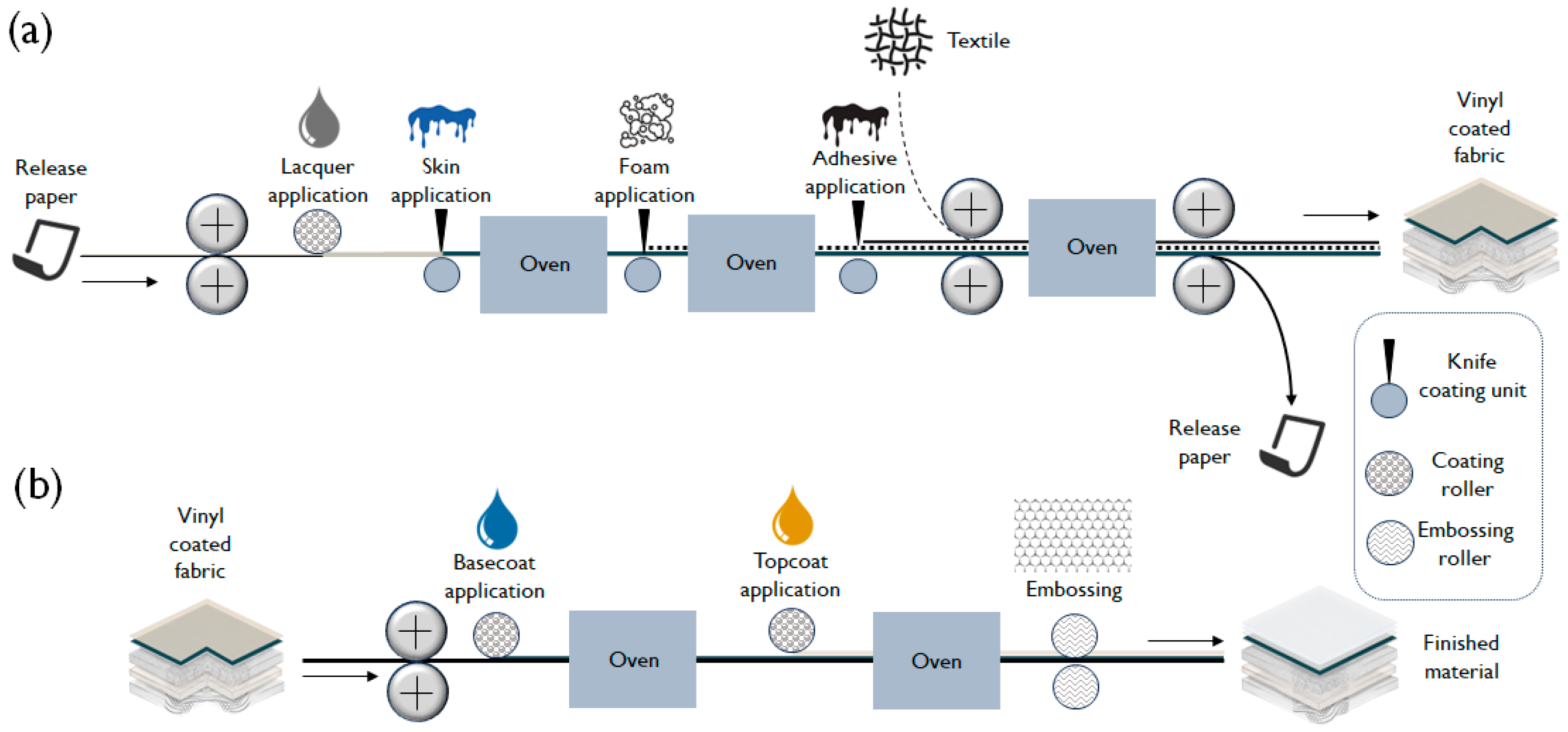
The construction of a vinyl coated fabric entails the application of PVC skin, foam, and adhesive layers by a transfer coating process over a release paper. Then, the textile is bonded to the polymeric layers by thermal lamination. Each layer is individually applied and cured at 200 °C. The release paper is pre-coated with a thin lacquer film to facilitate demolding once all PVC layers are bonded to the textile substrate. It should also be mentioned that one or two demolding lacquer layers can be applied to the release paper (Figure 2a), depending on the final product configuration.
After the generation process, the basic product construction is completed. To finish the coated fabric, a basecoat and high-performance water-based topcoat formulations intended for marine applications are individually applied with a rotogravure roller process, followed by an additional thermal curing step at 120 °C. Finally, all materials are passed through an embossing roller to give them aesthetic appearances similar to leather or textiles (Figure 2b).

2.3. Experimental Design

To identify the root cause of the failure in the vinyl coated fabric, a factorial experimental design comprising four factors and two levels was proposed (16 experiments). Two types of basecoat formulations (basecoat 1 and 2) were selected to evaluate the effect of the polymer type (acrylic and polyurethane) on the overall coated fabric construction. Also, two plasticizers with different molecular structures (type 1 and 2) were used in the skin plastisol formulation to identify any impact of plasticizer migration rate in the product integrity. Here, it is important to note that both the basecoat formulations and plasticizer types previously described are routinely and interchangeably used in the manufacturing processes, depending on commercial availability. The complete factorial design is displayed in Table 1. All samples were manufactured by Proquinal S.A.S. (Bogotá, Colombia), a company member of Spradling Group, with a minimum production run of 300 m.

2.4. Experimental Techniques

The FTIR spectra of coated fabrics and topcoat layers were collected using a FTIR Tensor II spectrophotometer (Bruker Optic GmbH, Ettlingen, Germany) coupled to a MIRacle diamond ATR module (PIKE Technologies, Madison, WI, USA) in the wavenumber range between 4000 and 600 cm−1. A total of 60 scans were carried out with a resolution of 4 cm−1.
Preliminary surface examination was carried out using a stereomicroscope ZEISS STEMI 508 with AXIOCAM ERc 5s camera (Zeiss, Oberkochen, Germany). Surface and cross-section microstructures of UV and thermal aged vinyl coated fabrics, and the corresponding elemental composition, were investigated using the scanning electron microscope (SEM) Lyra 3 (Tescan, Brno, Czechia) with a 5 kV acceleration voltage equipped with an energy dispersive spectrometer (EDS) analyzer X-Max80 (Oxford Instruments, Abingdon, UK).
The surface free energy (SFE) of samples after each step of the manufacturing process was measured using a Mobile Surface Analyzer (MSA) instrument (Krüss GmbH, Hamburg, Germany) at 34% RH and 23 °C. The droplet volume was set to 2 µL and the contact angles were measured 5 s after dosing. The total surface free energy (SFE) and its dispersive and polar components were calculated by the Advance software (version 1.16.0.10201, Krüss GmbH, Hamburg, Germany). employing the Owens–Wendt–Rabel–Kaelble (OWRK) approach (Equation (1)) where γl is the surface tension of the liquid, ϕ is the contact angle between the solid and test liquid, γsd is the dispersive component of the surface free energy, γsp is the polar component of the surface free energy, and γld and γlp are the dispersive and polar components of the surface tension of the liquid, respectively [14,15]. To calculate the polar (γsp) and dispersive (γsd) SFE components, two reference liquids were used: deionized water (polar liquid) and diiodomethane (non-polar liquid). The total SFE (γs) is the sum of both the disperse and polar components.
1 2 [ γ l 1 + cos φ ] = γ s d γ l d + γ s p γ l p
To estimate the molecular weight distribution, a GPC analysis was carried out in a Thermo Scientific Ultimate 3000 LC system (Thermo Fisher Scientific, West Palm Beach, FL, USA) coupled to a refractive index (RI) detector. Samples (5 mg) were analyzed through a PLgel MiniMIX-D column (4.6 × 250 mm, 5 µm) (Agilent, Santa Clara, CA, USA). The temperature of the column was kept constant at 35 °C. The mobile phase was HPLC-grade tetrahydrofuran at a flow rate of 1 mL/min, using 200 µL as the injection volume.
The thermal stability of both basecoat and topcoat films was determined with thermal gravimetric analysis (TGA) experiments using a Q500 thermal analyzer (TA Instruments, New Castle, DE, USA). Samples were heated from 30 to 600 °C with a heating rate of 10 °C/min.
To analyze the thermal transitions of films, differential scanning calorimetry (DSC) experiments were carried out using a DSC TA 250 Discovery series (TA Instruments, New Castle, DE, USA). The standard protocol involved two consecutive heating cycles from −40 °C to 120 °C at a rate of 20 °C/min. For the analysis of delaminated topcoat material, a modulated heating procedure was employed with a heating rate of 5 °C/min, an amplitude of ±2 °C, and a period of 40 s.

2.5. Plasticizer Extraction

The plasticizer extraction and quantification of the vinyl coated fabric was carried out using an UltiMate Thermo Fisher 3000 HPLC/UHPLC chromatographic system (Thermo Fisher Scientific, West Palm Beach, FL, USA) coupled to a Pinnacle II C18 5 μm 250 × 4.6 mm column (Restek, Centre County, PA, USA) and kept at 40 °C. A mixture of acetonitrile/methanol/water (HPLC grade) at 1 mL/min flux was employed as the mobile phase. The elution gradient system employed for chromatographic analysis is summarized in Table 2.
The sample injection volume was 10 μL and a Diode Arrangement Detector (DAD) set at 269 nm was used for detection. The calibration curves were built from standard plasticizer solutions in the range of 800–2000 mg/L. The extraction of the plasticizer from the vinyl fabrics involved direct contact of the material surface (16.3 cm2) with 40 mL of ethanol at 30 °C. Aliquots of 1 mL were taken after 1, 2, and 3 h of extraction and, later, analyzed by HPLC.

2.6. Accelerated Aging Tests

2.6.1. Salt Fog Chamber Exposure

Experiments were carried out in a cyclic CCT600 corrosion chamber (Q-FOG, Cleveland, OH, USA) under ASTM B117:19 standard [16]. Samples were cut into 10 cm × 15 cm specimens and exposed for 168 h at 35 °C.

2.6.2. UV Light Exposure

The accelerated weathering evaluations were carried out following three different standard procedures with their corresponding equipment:
ASTM D4329: Performed in a QUV/Spray Accelerated Weathering Tester (Q-Lab Corporation, Westlake, OH, USA) [17].
ISO 105B 04: Performed in a Ci4400 Xenon Weather-Ometer aging chamber (Atlas, Mount Prospect, IL, USA) [18].
NTC 1479: Performed in a 220+ Xenotest aging chamber (Atlas, Mount Prospect, IL, USA) [19].

2.6.3. Thermal Exposure

Vinyl coated fabric samples were cut into 15 pieces of 3.5 cm × 2.0 cm and placed in a FD53 E2 convection oven (BINDER GmbH, Tuttlingen, Germany) at 100 °C for a 15-day period. Each day, one of the pieces was taken from the oven and visually examined to detect any change in color, whitening, or deterioration compared to the corresponding unexposed material.

3. Results and Discussion

3.1. Preliminary Analysis of the Delaminated Vinyl Coated Fabric Identified During the Development Process

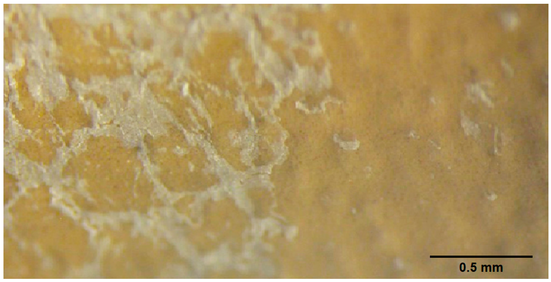
The macroscopic analysis of the failed reference vinyl coated fabric assembled with the same product construction of sample 9 (Table 1), showed a severe whitening on the surface accompanied by a topcoat delamination as displayed in Figure 3. From this observation, an incomplete crosslinking of the topcoat layer was proposed as the first hypothesis of material failure to be validated.
To explore the crosslinking condition of the topcoat layer for the damaged vinyl coated fabric, some detached polymer flakes were collected from the surface and analyzed using FTIR and DSC. Results were compared with the undamaged topcoat material containing different crosslinking degrees. A survey of the FTIR results showed that the IR spectrum of the detached coating retains the main absorption features of the undamaged crosslinked topcoat material (Figure 4a). However, a shift in the carbonyl stretching band from 1735 to 1720 cm−1 and the appearance of a new band at 730 cm−1 ascribed to aromatic C-H out of plane deformations suggested that the damaged coating layer absorbed a significant amount of plasticizer [20]. This finding is further corroborated by a comparison of the IR spectrum of the detached coating with that of plasticizer (Figure 4a).
Furthermore, the DSC thermograms (Figure 4b) confirmed the observations made by FTIR regarding polymer crosslinking. The undamaged topcoat polymer formulations showed a glass transition temperature (Tg) value that proportionally increases with the crosslinking degree, from 73 to 101 °C. Moreover, undamaged topcoat polymer formulations displayed a second Tg that remained constant at 157 °C. Note that, both Tg values estimated from the DSC curve of the delaminated coating shifted to lower temperatures, clearly indicating that this material has been plasticized during outdoor exposure. It should also be highlighted that the previous experiments demonstrated that the topcoat layer did not undergo any type of chemical degradation, or lack of crosslinking. Instead, these results suggest a plasticization phenomenon. With this information in hand, the incomplete topcoat crosslinking hypothesis was disregarded.

3.2. Experimental Design and Effect of Salt Fog and Temperature on the Vinyl Coated Fabric Samples

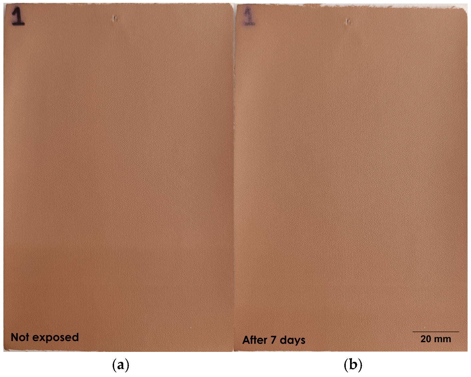
Once the reference sample that showed delamination throughout the development process was preliminary evaluated, all samples included in the experimental design were exposed to salt fog accelerated aging for 7 days as an attempt to determine if salty water may have induced any deterioration in the coating layers. Interestingly, no evidence of surface damage, discoloration, or coating fracture was observed after exposure in all samples. This confirmed that salt fog conditions do not cause any damage to the vinyl coated fabrics. Sample 1 was selected as a representative example to demonstrate the outcome of the test (see Figure 5).
In the same way, all samples were subjected to thermal accelerated aging (at 100 °C for 15 days) to simulate the conditions that vinyl coated fabrics could experience under direct sunlight illumination. Moreover, after each day of exposure, the vinyl coated fabrics were folded at the midpoint to induce mechanical stress. A close monitoring of the vinyl coated fabrics surface revealed the emergence of a white stripe after folding the specimens entailing only the basecoat formulation 2 (samples 9–16). This defect became visible after an average of 4 days of testing. Table 3 presents a representative surface defect (sample 9) that is compared to an unaffected surface (sample 1) for illustrative purposes.
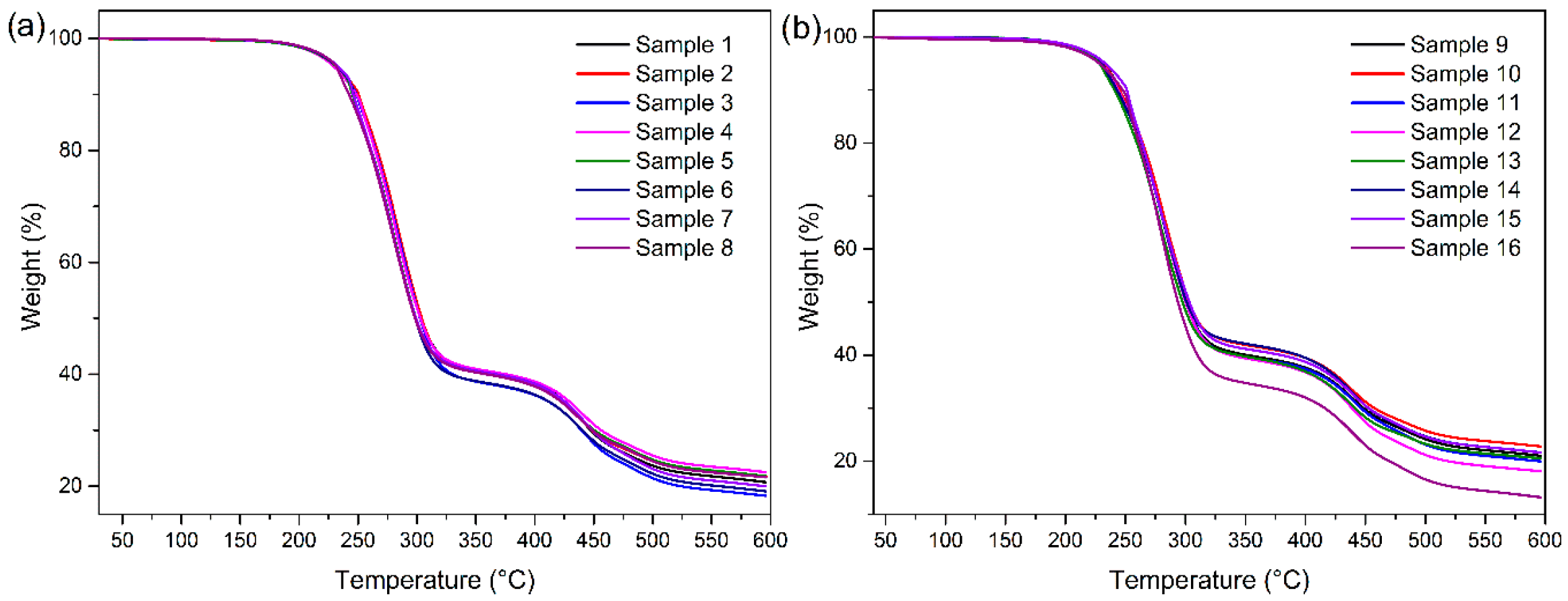
To validate that the white stripe observed after folding the specimens is not associated with a thermal degradation of any layer in the vinyl coated fabrics, TGA analyses were conducted. All curves (Figure 6) displayed a major degradation step starting at approximately 225 °C attributed to PVC and plasticizer decomposition. As TGA experiments showed no thermal degradation below 200 °C, it was confirmed that the observed whitening of the surface in the thermally exposed materials is not related to a degradation phenomenon but could be the result of a potential delamination of the coating system in samples assembled with the basecoat formulation 2 (samples 9–16).

3.3. Study of the Surface Free Energy of Coatings on Vinyl Fabrics

To clarify a potential adhesion issue, it was necessary to evaluate the compatibility between the coating layers used in the different vinyl coated fabric assemblies included in the experimental design. Therefore, the surface free energy (SFE) after each step of the coating process was estimated using the OWRK approach [15].
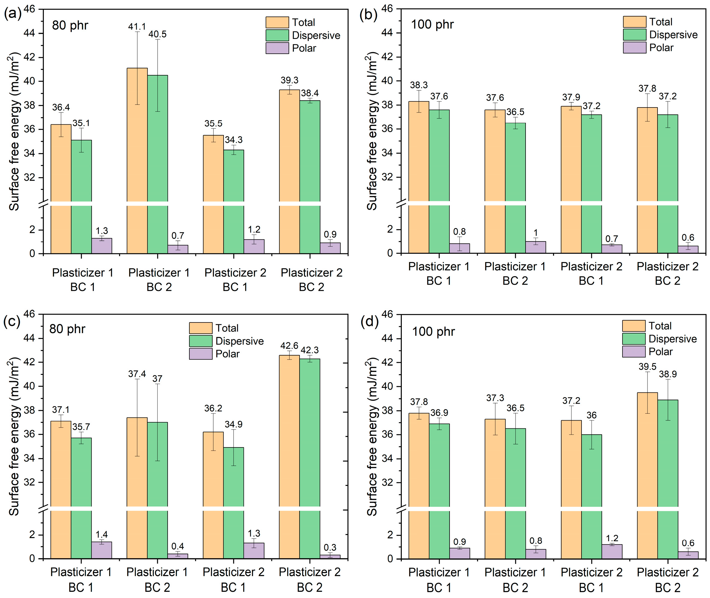
From the results (Table 4, Figure 7), it is noted that the total SFE values after the application of the basecoat formulation 2 are considerably affected by the plasticizer content of the PVC skin layer. An increase in the plasticizer content from 80 to 100 phr induces a decrease in the SFE value of approximately 4 mJ/m2. Taking into consideration that plasticizer migration occurs over time in the vinyl fabric, it can be expected that the surface free energy for basecoat formulation 2 increases as result of an accumulation of exudated plasticizer, leading to a decrease in the work of adhesion between the topcoat and basecoat layers by means of a physical interference and a modification in the molecular forces [21].
In addition, a complementary analysis of the polar (γsp) and dispersive (γsd) surface energy components was performed for all product configurations as displayed in Table 4. As anticipated, in all coated fabric constructions, the topcoat layer displays SFE values lower than 17 mJ/m2 attributed to the presence of fluorinated segments in its polymer backbone [22]. Furthermore, the individual polar SFE component for these finish topcoats (2–3 mJ/m2) indicates that approximately 10% of their surfaces exhibit available polar groups capable of effectively participating in strong non-covalent bonding with the basecoat layer [23].
The SFE data for coated fabric constructions with a single layer of demolding lacquer indicated that the polar component of the surface free energy in basecoat 2 is up to 45% lower compared to basecoat 1 when applied on PVC substrates with 80 phr of plasticizer (Figure 7a). Conversely, for vinyl constructions with a plasticizer level of 100 phr, the polar surface free energy value for both basecoat types is consistent when the same plasticizer is used (Figure 7b).
Surprisingly, a more noticeable reduction in approximately 75% of the polar component surface energy for basecoat 2, in contrast with basecoat 1, was observed for constructions with a double demolding lacquer application and 80 phr plasticizer level (Figure 7c). It should also be noted that coated fabrics with a plasticizer concentration of 100 phr displayed a similar behavior to samples with a single lacquer layer and only negligible differences in the polar SFE are found among basecoat formulations (Figure 7d).
The observed modification in γsp for basecoat 2 affects the number of available polar groups capable of creating strong non-covalent bonds with the topcoat layer. Once more, considering a realistic migration scenario, a reduction in the plasticizer content in the PVC substrate over time correlates with a dramatic compromise of the adhesive strength in the coating system joint (basecoat 2/topcoat). The above explains the surface defects and whitening observed after folding when these materials (samples 9–16) were placed under thermal treatment (Table 3, sample 9).
Therefore, the basecoat 1, which is vinyl acrylic in nature, showed a better performance as the surface energy components for this polymer layer are less influenced by the plasticizer concentration in the PVC substrate and, thus, the adhesion with the topcoat is consistently preserved over time.
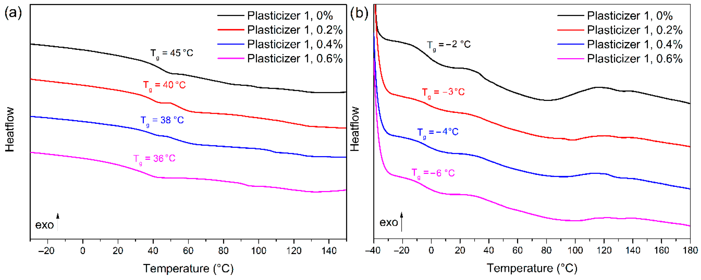
Aiming to correlate the evidence provided by SFE which indicates the potential plasticizer retention in the basecoat layers, a supplementary test was conducted. Four basecoat films for each formulation were carefully cast on a glass slide after the addition of 0.2, 0.4, and 0.6 wt% of plasticizer type 1, respectively. The changes in Tg values for each film were monitored using DSC (Figure 8).
Unexpectedly, the basecoat formulation 1 displayed a decrease in the Tg value of 9 °C after the addition of 0.6 wt% plasticizer 1 (Figure 8a). In contrast, basecoat formulation 2 exhibited a Tg value net reduction in only 4 °C when the same concentration of plasticizer was added (Figure 8b). These results confirmed that a better plasticization efficiency is achieved for basecoat 1. Conversely, basecoat 2 is unable to absorb the plasticizer, promoting the accumulation of this additive on the surface and causing a modification of the adhesive strength with the topcoat layer [24,25].

3.4. Plasticizer Extraction and Barrier Properties of the Coating on Vinyl Coated Fabrics

Plasticizer extraction experiments were carried out in vinyl coated fabrics to obtain quantitative information on the barrier effect exerted after the application of consecutive coating layers (Figure 9). This barrier ability has been reported to be a consequence of adequate adhesion and good interface properties between all layers [26].
After the application of the basecoat 1 (BC 1) on the skin formulation containing plasticizer 1, no major changes in the total amount of plasticizer extracted from this construction were observed after 3 h of extraction (Figure 9a). However, a difference in the extraction profile curve related to the plasticizer rate of diffusion was noted as it follows a marked linear behavior after the basecoat application [27]. Once the application of the finish topcoat layer (TC) was completed (Figure 9b), a significant reduction of approximately 50% in the overall plasticizer extraction was observed, suggesting that the combination between the basecoat 1 and the topcoat affords an additional barrier against the plasticizer extraction. This evidence is a consequence of good adhesion between layers.
The same experiment was carried out after the application of the basecoat 2 (BC 2) on the skin layer (Figure 9c), where a similar extraction pattern when compared to basecoat 1 was noted. Surprisingly, after the application of the topcoat (Figure 9d), the extraction profile remained almost unaffected and no significant reduction in the plasticizer 1 extraction was evidenced. This outcome indicated poor adhesion between the basecoat 2 and the finish topcoat layer that prevents the latter from acting as an additional barrier against plasticizer 1 extraction. Similar results and patterns were obtained for all materials comprising plasticizer 2 (samples 13–16).

3.5. Effect of UV Light on the Vinyl Coated Fabric and the Coating

To verify the UV light resistance of both basecoat formulations, all vinyl coated fabric constructions after the sole application of the basecoat layer were exposed under three different accelerated weathering conditions (ASTM D4329, ISO 105B 04, and NTC 1479) [17,18,19]. Although the evaluation of specimens after the UV weathering tests mainly evaluates a color change comparison against a reference sample, we have also applied mechanical deformation on the material (e.g., folding, scratching, etc.) aiming to validate the coating integrity and the adhesion of the basecoat to the substrate.
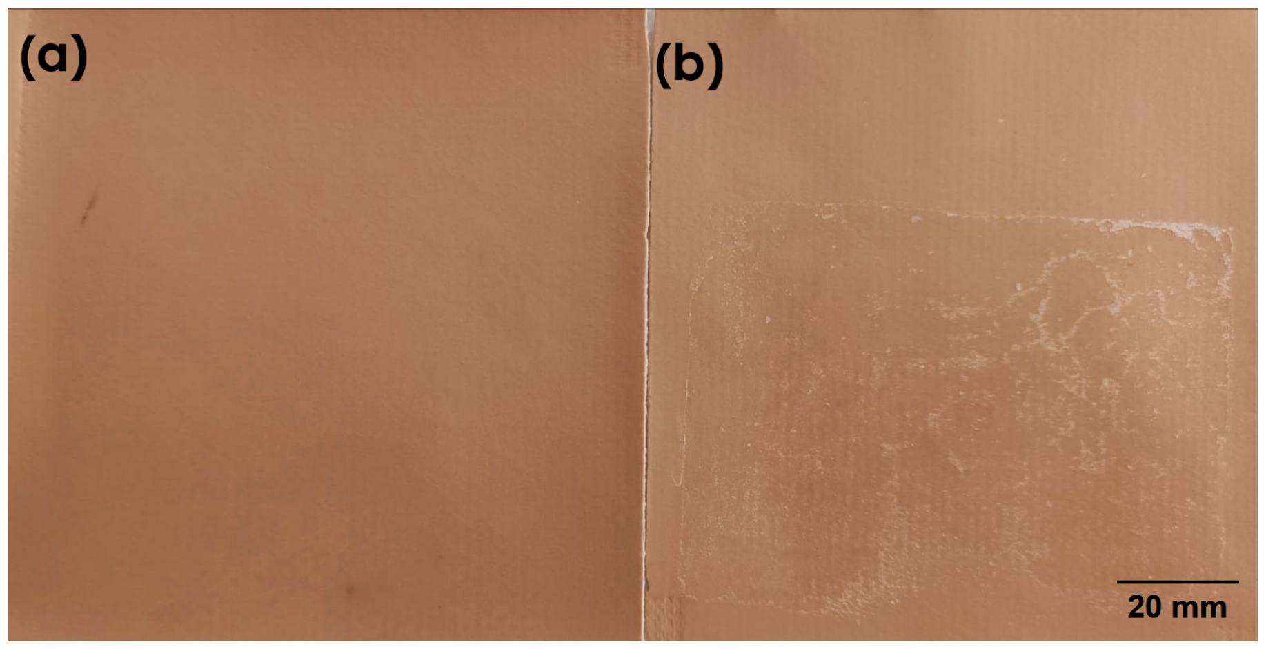
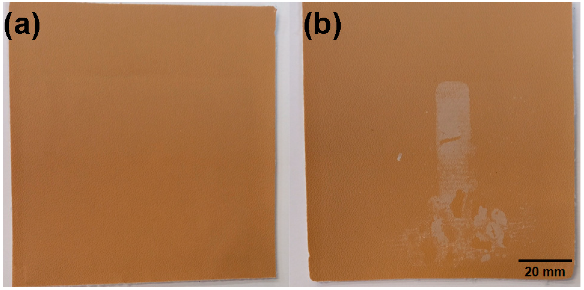
After the accelerated weathering tests were completed, the surface for all samples was examined. Interestingly, no changes or whitening were observed for the vinyl coated fabrics that were coated with basecoat 1 (Figure 10a) even after mechanical deformation. Conversely, samples with basecoat 2 displayed serious surface defects that included whitening and cracking (Figure 10b).
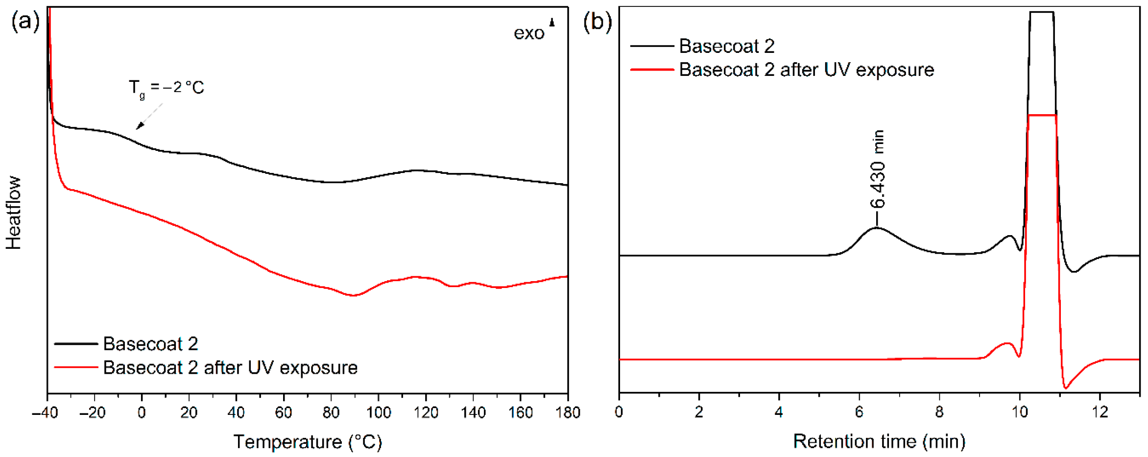
As an attempt to understand the damage mechanism and to assess the molecular integrity of basecoat 2 after UV irradiation, a mechanical removal of the surface debris from sample 14 was carried out and analyzed by DSC. The analysis reveals the disappearance of the glass transition temperature (Tg) (Figure 11a). To confirm if those results were a consequence of excessive plasticization of the basecoat layer, the molecular integrity of the basecoat polymer debris was evaluated with GPC experiments (Figure 11b) [28]. While the reference chromatogram for basecoat 2 shows a peak at 6.4 min corresponding to the molecular weight distribution of its main polymer, no signal was detected for the UV-exposed sample. This observation unequivocally confirms that the polymer in basecoat 2 experienced complete photodegradation under UV exposure conditions.
Similarly, all samples bearing the full coating system (basecoat and topcoat) were also exposed to UV accelerated weathering conditions. Once more, only minor changes and hardly noticeable white spots after folding were observed for some samples containing the basecoat 1 (Figure 12a). Strikingly, all materials containing basecoat 2 showed severe surface damage accompanied by detachment of the coating (Figure 12b). The removed material from the most damaged samples was analyzed by GPC. No chromatographic peaks were detected for either the reference topcoat or the damaged samples, likely due to the highly crosslinked nature of the topcoat, which is insoluble in the solvent used (THF). Additionally, the polymer peak for basecoat 2 was also absent. Based on these results, it was not possible to determine whether both the basecoat and topcoat layers had detached from the samples containing basecoat 2.

3.6. Microscopy Evaluation

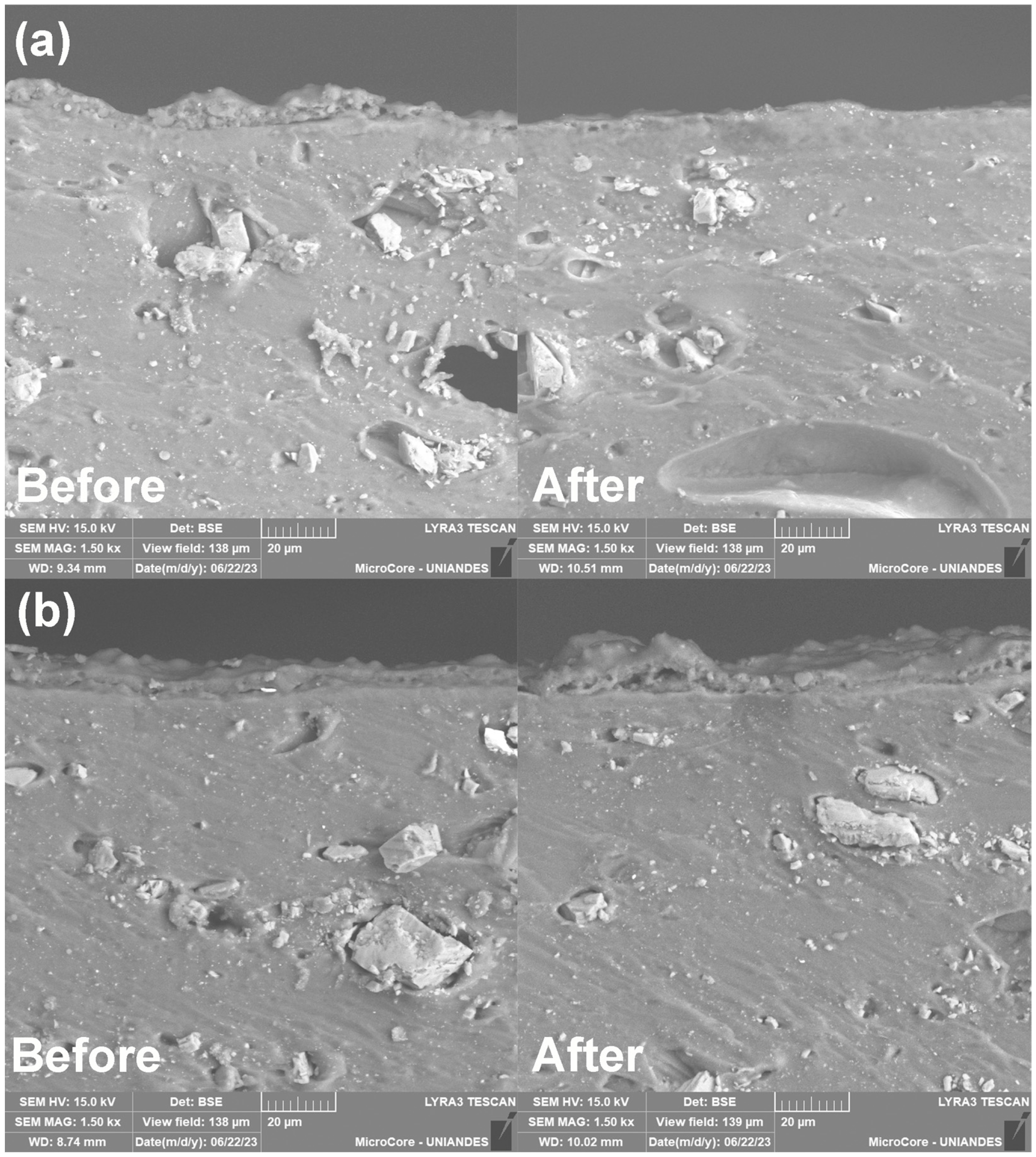
To analyze the location of the interface within the vinyl coated fabric assembly that is evidencing the adhesion failure in the topcoat system, SEM was used to evaluate samples before and after UV and thermal aging. Additional elemental mapping (EDS) was performed to accurately discern the topcoat layer from the basecoat in virtue of its fluorine content.
The samples containing the basecoat 1 before UV irradiation (Figure 13a) displayed that there are no adhesion issues as the basecoat and topcoat layers are continuously adhered to one another. Moreover, the thickness of basecoat and topcoat layers was estimated from SEM micrographs and corresponds to 2.7 and 2.5 µm, respectively. After UV exposure (Figure 13b), the basecoat and topcoat layers showed no evidence of adhesive failure between them. Conversely, the coating layers appeared to be merged as confirmed by the slight decrease in the layer thickness (2.0 and 2.3 µm for basecoat and topcoat, respectively) when compared to the unexposed material.
An analog SEM survey of the vinyl coated fabrics containing the basecoat 2 allows the identification of discontinuities in the evaluated cross-section before irradiation (Figure 13c). Likewise, the thicknesses of the basecoat and topcoat are 2.8 and 3.1 µm, respectively. Although the topcoat thickness has increased by approximately 0.6 µm in this non-irradiated vinyl fabric sample (basecoat 2) when compared to the product assembly encompassing basecoat 1, it is worth noting that such difference is within the tolerance range for the roller coating process under typical production plant conditions.
After UV weathering exposure, SEM micrographs displayed a severe adhesion failure (Figure 13d). The elemental profiling allowed the unequivocal identification of the layer that is being detached from the vinyl skin, and it corresponds to the topcoat as denoted by its fluorine content. It should also be disclosed that the thickness of the topcoat has increased to 6.0 µm. This swelling can be associated with the absorption of plasticizer as evidenced by FTIR experiments for the damaged material (Figure 3). Moreover, the carbon and oxygen densities in the elemental profile corroborate that the basecoat layer remains adhered to the vinyl fabric despite being severely affected by UV light, as previously outlined.
Analog results were obtained for samples containing plasticizer 2 in the skin layer, validating that the type of plasticizer molecule does not have any influence over the performance of the topcoat adhesive joint with basecoat 2.
Finally, a similar evaluation of materials exposed to high temperature conditions was carried out. In general, samples entailing basecoat 1 (Figure 14a) exhibit a decrease in the coating system thickness from 5.1 to 3.8 µm that relates to a temperature-facilitated merging behavior between the basecoat and topcoat layers in contact. In contrast, samples assembled with basecoat 2 (Figure 14b) not only display regions where a discontinuity between the basecoat and topcoat layers is clearly evidenced, but a swelling phenomenon of the topcoat is also identified, supported by the increase in the coating system thickness from 5.3 to 9.5 µm. These SEM results confirm that both UV and thermal aging conditions prompted the topcoat detachment in all vinyl coated fabric constructions entailing the use of basecoat 2 formulation.

4. Conclusions

The proposed experimental design, the tests conducted on the vinyl coated fabric specimens, and the analytical techniques employed provided a thorough understanding of the factors influencing the adhesion and stability of the coating system along with the exact mode of failure in these multilayered materials.
It was demonstrated that the observed vinyl coated fabric failure spotted during the product development process resulted from a combination of weak adhesion between the basecoat 2 and the topcoat layer which is a consequence of their difference in the polar free surface energy components and the modification of the total free surface energy of the basecoat during the plasticizer migration process. Moreover, a poor UV resistance of the polyurethane polymer in this same basecoat formulation was corroborated. Both phenomena led to the early detachment of the finish topcoat from the basecoat layer, as confirmed by SEM observations.
Furthermore, the extraction and chromatographic quantitative analysis of plasticizers was found to be an effective methodology to assess and predict the interlayer adhesion of the coating system in vinyl coated fabrics. The implementation of this methodology in the coated fabrics industry will serve as a valuable tool to optimize coating formulations by allowing early detection of potential adhesion failures, significantly reducing the time required during the product development process. The results of this study will also help ensure the long-term durability and reliable performance of coated fabrics in highly demanding applications such as marine upholstery.

Author Contributions

Conceptualization, M.A., J.L.-B. and J.M.M.-M.; methodology, M.A., C.C., G.J.P.; validation, M.A., N.T.Z.-G., P.P., J.L.-B. and J.M.M.-M.; investigation, N.T.Z.-G., P.P. and C.C.; writing—original draft preparation, M.A. and J.L.-B.; writing—review and editing, M.A., G.J.P., J.L.-B. and J.M.M.-M.; visualization, M.A. and J.L.-B.; supervision, M.A., J.L.-B. and R.S.; project administration, R.S. and J.L.-B. All authors have read and agreed to the published version of the manuscript.

Funding

This work was financed by Proquinal S.A.S. through its Research and Development Department, Project 12040.

Institutional Review Board Statement

Not applicable.

Informed Consent Statement

Not applicable.

Data Availability Statement

The original contributions presented in the study are included in the article, further inquiries can be directed to the corresponding author.

Acknowledgments

Authors would like to thank Laboratorio de Investigación en Polímeros, Universidad de Antioquia for their support with the HPLC analysis.

Conflicts of Interest

Authors Mauricio Acelas, Cristina Combariza, Natalia Trinidad Zapata-Gallego, Paula Pinto, Gabriel J. Peláez, Ricardo Santana, and Juliana Lasprilla-Botero were employed by the company Proquinal S.A.S.—Spradling Group. The remaining authors declare that the research was conducted in the absence of any commercial or financial relationships that could be construed as a potential conflict of interest.

Abbreviations

The following abbreviations are used in this manuscript:
PVCPoly(vinyl chloride)
UVUltraviolet radiation
SEMScanning electron microscopy
γsTotal surface free energy
γsdDispersive free energy component
γspPolar free energy component
SFESurface free energy
DSCDifferential scanning calorimetry
TGAThermogravimetric analysis
TgGlass transition temperature
FTIRFourier Transform Infrared Spectroscopy
ATRAttenuated Total Reflectance
GPCGel permeation chromatography
HPLCHigh-Performance Liquid Chromatography
BCBasecoat
phrParts per hundred resin

References

  1. Ryu, J.; Hao, L.T.; Kim, H.; Lee, S.; Jeon, H.; Hwang, D.S.; Park, J.; Park, C.H.; Oh, D.X.; Koo, J.M.; et al. Biobased poly(ester amide)s as sustainable coating materials for vegan leather with improved haptic sensation. ACS Sustain. Chem. Eng. 2025, 13, 7585–7597. [Google Scholar] [CrossRef]
  2. Meyer, M.; Dietrich, S.; Schulz, H.; Mondschein, A. Comparison of the Technical Performance of Leather, Artificial Leather, and Trendy Alternatives. Coatings 2021, 11, 226. [Google Scholar] [CrossRef]
  3. Cheng, J.; Cao, Y.; Jiang, S.; Gao, Y.; Nie, J.; Sun, F. Synthesis and Performances of UV-Curable Polysiloxane-Polyether Block Polyurethane Acrylates for PVC Leather Finishing Agents. Ind. Eng. Chem. Res. 2015, 54, 5635–5642. [Google Scholar] [CrossRef]
  4. Bautista, M.; Lasprilla-Botero, J.; Mendez, J.; Alvarez, J.; Forero, A.; Santana, R. Investigación y Tecnología en Telas de Tapicería con Altos Niveles de Desempeño Recubiertas con Polímeros por Transferencia. Rev. Colomb. Mater. 2020, 15, 1–7. [Google Scholar]
  5. Liu, Z.; Zheng, X.; Zhang, H.; Li, W.; Jiang, R.; Zhou, X. Review on Formation of Biofouling in the Marine Environment and Functionalization of New Marine Antifouling Coatings. J. Mater. Sci. 2022, 57, 18221–18242. [Google Scholar] [CrossRef]
  6. Sun, Z.; Ren, S.; Wu, T.; Wen, J.; Fang, J.; Fan, H. A Self-Matting Waterborne Polyurethane Coating for PVC Artificial Leather. Polymers 2023, 15, 127. [Google Scholar] [CrossRef]
  7. Ammar, S.; Ma, I.A.W.; Ramesh, K.; Ramesh, S. Polymers-Based Nanocomposite Coatings. In Nanomaterials-Based Coatings: Fundamentals and Applications; Elsevier: Amsterdam, The Netherlands, 2019; pp. 9–39. ISBN 9780128158845. [Google Scholar]
  8. Liu, J.; Recupido, F.; Lama, G.C.; Oliviero, M.; Verdolotti, L.; Lavorgna, M. Recent Advances Concerning Polyurethane in Leather Applications: An Overview of Conventional and Greener Solutions. Collagen Leather 2023, 5, 8. [Google Scholar] [CrossRef]
  9. Gardi, S.; Giannone, L.; Sarti, G.; Sarti, G. Surface Chalking upon Weathering of Dark-Colored PVC Articles and Relevant Stabilizers. Polymers 2024, 16, 1047. [Google Scholar] [CrossRef] [PubMed]
  10. Gardi, S.; Giannone, L.; Sarti, G.; Sarti, G.; Costa, M. Influence of Initial Season on PVC Weathering. Polym. Test. 2023, 125, 108123. [Google Scholar] [CrossRef]
  11. Al-Dossary, A.K.; Gilbert, M.; Hitt, D. Evaluating PVC Degradation Using UV and Raman Spectroscopies. Adv. Mater. Res. 2010, 83–86, 923–930. [Google Scholar] [CrossRef]
  12. Palaniappan, E. Natural and Artificial Weathering of Automotive Leather, Leatherette and Textile; SAE Technical Paper 2019-28-0091; SAE International: Warrendale, PA, USA, 2019. [Google Scholar] [CrossRef]
  13. Dobilaitė, V.; Jucienė, M.; Bliūdžius, R.; Šveikauskaitė, L. Investigation of some weathering impacts on tearing properties of PVC-coated fabrics used for architectural purposes. J. Ind. Text. 2020, 51, 5328S–5346S. [Google Scholar] [CrossRef]
  14. Owens, D.K.; Wendt, R.C. Estimation of the Surface Free Energy of Polymers. J. Appl. Polym. Sci. 1969, 13, 1741–1747. [Google Scholar] [CrossRef]
  15. Peršin Fratnik, Z.; Plohl, O.; Kokol, V.; Fras Zemljič, L. Using Different Surface Energy Models to Assess the Interactions between Antiviral Coating Films and Phi6 Model Virus. J. Funct. Biomater. 2023, 14, 232. [Google Scholar] [CrossRef]
  16. ASTM B117-19; Standard Practice for Operating Salt Spray (Fog) Apparatus. American Society for Testing and Materials: West Conshohocken, PA, USA, 2019.
  17. ASTM D4329-21; Standard Practice for Fluorescent Ultraviolet (UV) Lamp Apparatus Exposure of Plastics. American Society for Testing and Materials: West Conshohocken, PA, USA, 2021.
  18. ISO 105-B04:2024; Textiles—Tests for Colour Fastness—Part B04: Colour Fastness to Artificial Weathering: Xenon Arc Fading Lamp Test. International Standard Organization: Geneva, Switzerland, 2024.
  19. NTC 1479-2; Texitles. Test for Colorfastness. Part 2: Colorfastness to Artificial Ligth. Zenon Arc Fading Lamp Test. ICONTEC—Instituto Colombiano de Normas Técnicas: Bogotá, Colombia, 2016.
  20. Coltro, L.; Pitta, J.B.; Madaleno, E. Performance Evaluation of New Plasticizers for Stretch PVC Films. Polym. Test. 2013, 32, 272–278. [Google Scholar] [CrossRef]
  21. Mallikarjunachari, G.; Ghosh, P. Analysis of Strength and Response of Polymer Nano Thin Film Interfaces Applying Nanoindentation and Nanoscratch Techniques. Polymer 2016, 90, 53–66. [Google Scholar] [CrossRef]
  22. Peng, H. Synthesis and Application of Fluorine-Containing Polymers with Low Surface Energy. Polym. Rev. 2019, 59, 739–757. [Google Scholar] [CrossRef]
  23. Gong, L.; Xiang, L.; Zhang, J.; Chen, J.; Zeng, H. Fundamentals and Advances in the Adhesion of Polymer Surfaces and Thin Films. Langmuir 2019, 35, 15914–15936. [Google Scholar] [CrossRef]
  24. Ivorra-Martinez, J.; Peydro, M.A.; Gomez-Caturla, J.; Boronat, T.; Balart, R. The Potential of an Itaconic Acid Diester as Environmentally Friendly Plasticizer for Injection-Molded Polylactide Parts. Macromol. Mater. Eng. 2022, 307, 2200360. [Google Scholar] [CrossRef]
  25. Stachowiak, N.; Kowalonek, J.; Kozlowska, J. Effect of Plasticizer and Surfactant on the Properties of Poly(Vinyl Alcohol)/Chitosan Films. Int. J. Biol. Macromol. 2020, 164, 2100–2107. [Google Scholar] [CrossRef] [PubMed]
  26. Massard, C.; Bernard, L.; Cueff, R.; Raspal, V.; Feschet-Chassot, E.; Sibaud, Y.; Sautou, V.; Awitor, K.O. Photopolymerizable Hybrid Sol Gel Coating as a Barrier against Plasticizer Release. Prog. Org. Coat. 2012, 75, 116–123. [Google Scholar] [CrossRef]
  27. Dedov, A. V Simulation of the Kinetics of Plasticizer Extraction with Ethanol. Russ. J. Appl. Chem. 2003, 76, 2033–2037. [Google Scholar] [CrossRef]
  28. Xu, Y.; Morado, E.G.; Zimmerman, S.C. Construction from Destruction Using a Photo-Triggered Self-Propagating Degradable Polyurethane as a One-Pot Epoxy. Polym. Chem. 2020, 11, 6215–6220. [Google Scholar] [CrossRef]
Figure 1. Schematic multilayered representation of a vinyl coated fabric and its coating system.
Coatings 15 01365 g001
Figure 2. Vinyl coated fabric construction process: (a) generation and (b) finishing process.
Coatings 15 01365 g002
Figure 3. Examination of the detached topcoat area of the damaged vinyl coated fabric material under optical microscope (10×).
Coatings 15 01365 g003
Figure 4. (a) Comparative coating FTIR spectra set and (b) comparative DSC thermograms for the delaminated polymer flakes taken from the vinyl coated fabric that failed during the development process.
Coatings 15 01365 g004
Figure 5. Sample 1 (a) before and (b) after exposure to salt fog accelerated aging.
Coatings 15 01365 g005
Figure 6. TGA curves of vinyl coated fabrics (a) containing basecoat formulation 1 and (b) containing basecoat formulation 2.
Coatings 15 01365 g006
Figure 7. SFE components for different basecoat constructions containing (a) single demolding lacquer application and 80 phr of plasticizer, (b) single demolding lacquer application and 100 phr of plasticizer, (c) double demolding lacquer application and 80 phr of plasticizer, and (d) double demolding lacquer application and 100 phr of plasticizer.
Coatings 15 01365 g007
Figure 8. DSC curves of basecoat film on glass slide with different plasticizer concentration for (a) basecoat formulation 1, and (b) basecoat formulation 2.
Coatings 15 01365 g008
Figure 9. Plasticizer 1 migration profile for vinyl coated fabrics after the application of (a) basecoat 1 (BC 1); (b) basecoat 1 and topcoat (BC 1 + TC); (c) basecoat 2 (BC 2); and (d) basecoat 2 and topcoat (BC 2 + TC).
Coatings 15 01365 g009
Figure 10. Representative surface examination after ASTM D4329 [13] accelerated QUV weathering test for (a) sample 6 (basecoat 1) and (b) sample 14 (basecoat 2). These vinyl coated fabric samples differ only in the basecoat type.
Coatings 15 01365 g010
Figure 11. Evaluation of removed basecoat 2 from sample 14 before and after UV exposure by (a) DSC and (b) GPC analysis.
Coatings 15 01365 g011
Figure 12. Surface examination after ASTM D4329 accelerated weathering test for (a) sample 2 (basecoat 1) and (b) sample 10 (basecoat 2), both with the complete coating system applied.
Coatings 15 01365 g012
Figure 13. Cross-section SEM examination of (a) sample 1 before UV irradiation, (b) sample 1 after UV irradiation, (c) sample 9 before UV irradiation, and (d) sample 9 after UV irradiation. These samples were selected as reference to exemplify the behavior of the coating system.
Coatings 15 01365 g013
Figure 14. Cross-section SEM examination of (a) sample 5 before and after high temperature exposure and (b) sample 13 before and after high temperature exposure. These samples were selected as reference to exemplify the behavior of the coating system.
Coatings 15 01365 g014
Table 1. Factorial design for the construction of vinyl coated fabric samples.
SampleType of Basecoat PlasticizerPlasticization Level (phr)Layers of Demolding Lacquer b
1Solvent-based vinyl acrylic
(BC 1)
Terephtalate
(plasticizer 1)
1001
22
3801
42
5Phtalate
(plasticizer 2)
1001
62
7801
82
9 aSolvent-based aliphatic polyurethane
(BC 2)
Terephtalate
(plasticizer 1)
1001
102
11801
122
13Phtalate
(plasticizer 2)
1001
142
15801
162
a Product assembly that failed the outdoor performance test. b Demolding lacquer applied in the generation process (Figure 2a).
Table 2. Gradient chromatographic conditions for the analysis of extracted plasticizers from vinyl coated fabric.
Time (min)Volume Fraction
CH3CN (%)CH3OH (%)H2O (%)
0–860355
8–1170300
11–1375250
13–1580200
15–2060355
Table 3. Comparative behavior and appearance of a white surface defect in selected samples 1 and 9 containing different basecoat formulations.
SampleType of Basecoat LayerThermal Exposure at 100 °C
0 Days7 Days15 Days
1BC 1Coatings 15 01365 i001Coatings 15 01365 i002Coatings 15 01365 i003
9BC 2Coatings 15 01365 i004Coatings 15 01365 i005Coatings 15 01365 i006
Table 4. Total surface free energy (γs) and dispersive (γsd) and polar (γsp) components of consecutive layers in the different vinyl coated fabrics assemblies.
Plasticizer
Content (phr)
Layers of Demolding LacquerPlasticizerEvaluated
Surface
γs (mJ/m2)γsd (mJ/m2)γsp (mJ/m2)
1001Type 1Skin layer45.4 ± 0.443.9 ± 0.21.5 ± 0.4
Basecoat 138.3 ± 0.937.6 ± 0.70.8 ± 0.6
Basecoat 237.6 ± 0.636.5 ± 0.51.0 ± 0.3
Finish Topcoat14.9 ± 0.912.8 ± 0.82.1 ± 0.5
Type 2Skin layer42.4 ± 0.639.2 ± 0.53.1 ± 0.3
Basecoat 137.9 ± 0.337.2 ± 0.30.7 ± 0.1
Basecoat 237.8 ± 1.137.2 ± 1.10.6 ± 0.3
Finish Topcoat15.4 ± 1.213.8 ± 1.11.7 ± 0.5
2Type 1Skin layer44.3 ± 0.942.8 ± 0.81.5 ± 0.4
Basecoat 137.8 ± 0.536.9 ± 0.50.9 ± 0.1
Basecoat 237.3 ± 1.336.5 ± 1.30.8 ± 0.3
Finish Topcoat15.0 ± 2.413.5 ± 2.31.5 ± 0.6
Type 2Skin layer40.5 ± 0.438.1 ± 0.12.5 ± 0.4
Basecoat 137.2 ± 1.236.0 ± 1.21.2 ± 0.1
Basecoat 239.5 ± 1.738.9 ± 1.70.6 ± 0.3
Finish Topcoat15.9 ± 1.514.0 ± 1.31.9 ± 0.7
801Type 1Skin layer39.6 ± 1.238.1 ± 1.11.5 ± 0.4
Basecoat 136.4 ± 1.035.1 ± 1.01.3 ± 0.2
Basecoat 241.1 ± 3.040.5 ± 3.00.7 ± 0.4
Finish Topcoat16.2 ± 1.913.3 ± 1.82.9 ± 0.7
Type 2Skin layer39.0 ± 0.637.5 ± 0.41.5 ± 0.4
Basecoat 135.5 ± 0.634.3 ± 0.41.2 ± 0.4
Basecoat 239.3 ± 0.438.4 ± 0.20.9 ± 0.3
Finish Topcoat14.8 ± 0.913.0 ± 0.81.8 ± 0.3
2Type 1Skin layer39.2 ± 0.638.0 ± 0.61.2 ± 0.1
Basecoat 137.1 ± 0.535.7 ± 0.51.4 ± 0.2
Basecoat 237.4 ± 3.237.0 ± 3.20.4 ± 0.2
Finish Topcoat16.8 ± 0.415.1 ± 0.21.70 ± 0.4
Type 2Skin layer37.9 ± 1.836.3 ± 1.51.6 ± 1.0
Basecoat 136.2 ± 1.634.9 ± 1.51.3 ± 0.4
Basecoat 242.6 ± 0.442.3 ± 0.30.3 ± 0.2
Finish Topcoat15.5 ± 0.412.3 ± 0.23.1 ± 0.4
Disclaimer/Publisher’s Note: The statements, opinions and data contained in all publications are solely those of the individual author(s) and contributor(s) and not of MDPI and/or the editor(s). MDPI and/or the editor(s) disclaim responsibility for any injury to people or property resulting from any ideas, methods, instructions or products referred to in the content.