Article

Preparation and Properties of Micro-Arc Oxidation Coatings on Friction-Stir-Processed ZK60 Mg Alloys with Hydroxyapatite Particles

1
School of Materials Science and Engineering, Jiangsu University of Science and Technology, Zhenjiang 212003, China
2
Department of Material Science and Technology of Metals, Admiral Makarov National University of Shipbuilding Institute, 54025 Nikolaev, Ukraine
*
Author to whom correspondence should be addressed.
Coatings 2025, 15(12), 1362; https://doi.org/10.3390/coatings15121362 (registering DOI)
Submission received: 3 November 2025 / Revised: 20 November 2025 / Accepted: 20 November 2025 / Published: 22 November 2025
(This article belongs to the Section Corrosion, Wear and Erosion)

Abstract

To address the challenges of excessively fast degradation and relatively poor biocompatibility of biomedical magnesium alloys, in this study, Mg/HA magnesium alloy treated by different friction stir processing (FSP) techniques served as the substrate for fabricating a micro-arc oxidation (MAO) coating. SEM, EDS, XRD, and XPS were employed to characterize the coating’s microstructure, phase composition, and element distribution, while its comprehensive properties were evaluated via electrochemical tests, nanoindentation, friction–wear experiments, contact angle measurements, and antibacterial assays. Results indicate that MAO coatings on all substrates exhibit a dense, uniform grayish-white macroscopic morphology with 3–5 μm pores. Cross-sectional observations reveal a metallurgical bond between the coating and substrate, with minor blind pores and microcracks distributed in the coating, and different coatings show similar thickness and high density. The coatings mainly consist of Ca3(PO4)2, CaCO3, Mg, MgSiO3, and MgO. HA powder is uniformly dispersed in the substrate treated by 1500-3 FSP passes, promoting more Ca2+ and PO43− release during the MAO process. This yields the highest Ca/P ratio, endowing the coating with excellent biological performance to induce osteocyte growth. All coatings have good wear/corrosion resistance and a maximum adhesion of 14.485 N. Notably, MAO coatings on substrates with 1500-3 and 1700-3 FSP passes are moderately hydrophilic, facilitating cell adhesion/spreading and meeting biomedical implants’ short-term antibacterial rate requirements.

1. Introduction

Magnesium and its alloys exhibit numerous advantages, including high specific strength and specific stiffness, excellent thermal and electrical conductivity, as well as ease of processing, forming, and recycling. They hold extremely important application value and have been widely used in engineering structure fields such as rail transit, aerospace, and electronic communication. In addition, magnesium alloys have attracted extensive attention in the field of new medical implant materials due to their density and mechanical properties being very close to those of human bone tissue, along with favorable safety, biocompatibility, and biodegradable/absorbable characteristics. However, the rapid degradation rate and poor bioactivity of magnesium alloys in the human body environment have limited their widespread application in the medical field [1,2].
Biomedical magnesium alloys, serving as bone implants, aim to provide support and facilitate new tissue regeneration, playing a vital role in the fracture healing process. An ideal implant should possess a porous structure to enable nutrient transport and tissue ingrowth, as well as appropriate mechanical strength matching that of the replaced bone to offer mechanical support and avoid stress shielding. It should also exhibit good biocompatibility to promote cell adhesion and proliferation. Most importantly, it must demonstrate controlled biodegradability in the human body to prevent risks such as physical irritation, local chronic inflammation, and the need for secondary surgery. Therefore, magnesium and its alloys, meeting these requirements, are regarded as revolutionary biodegradable metallic materials. Their unique advantages—including lightweight properties, mechanical strength comparable to natural bone, and excellent biosafety—have led to extensive research in orthopedic applications [3]. Compared with conventional metallic biomaterials [4,5,6,7], magnesium alloys exhibit a density and elastic modulus much closer to those of natural bone. This similarity not only improves load transfer between the implant and host tissue but also promotes bone regeneration and reduces the risk of stress shielding [8]. As magnesium is an essential element of the human body and a natural constituent of bone tissue, its gradual dissolution in vivo usually does not cause adverse biological effects, magnesium and its alloys can react rapidly with water to release Mg ions, and a moderate increase in Mg2+ concentration promotes the osteogenic and angiogenic activities of cells [9,10]. Furthermore, the biodegradable nature of magnesium alloys allows the implant to safely degrade as the surrounding tissue heals, eliminating the need for secondary surgery and reducing medical costs and patient discomfort [11]. Despite these benefits, pure magnesium and its alloys face significant challenges when exposed to physiological environments. Their high chemical reactivity and low standard electrode potential make them prone to rapid corrosion, producing Mg(OH)2 that can further react to form soluble salts such as MgCl2 [12,13]. The accelerated degradation weakens the mechanical integrity of the implant and may lead to premature failure before sufficient bone regeneration occurs. In addition, the sudden accumulation of Mg2+ ions can cause local alkalization, potentially affecting cell viability and tissue compatibility [14]. To address this technical challenge, many studies have focused on alloying design, surface modification, and the development of magnesium-based composites to slow down degradation and enhance biological performance.
Among various reinforcement strategies, introducing ceramic particles such as hydroxyapatite (HA), MgO, SiO2, and ZrO2 into the magnesium matrix has proven particularly effective [15,16,17]. These reinforcements improve hardness, wear resistance, and corrosion behavior while enhancing biocompatibility. FSP is a solid-state technique derived from friction stir welding, provides a reliable route to disperse such reinforcements into metallic substrates. FSP offers several advantages—fine-grain microstructures, homogeneous particle distribution, and the absence of detrimental intermetallic phases—while being cost-efficient and environmentally friendly [18,19]. Compared with traditional heat treatment or casting processes, friction stir processing (FSP) technology has many prominent advantages, especially in microstructure and defect control. It can effectively refine grains, eliminate casting pores, cracks, stress concentration and other defects. These advantages enable friction stir processing to perform excellently in improving material properties and optimizing processing effects, possessing broad application prospects. Hydroxyapatite, as the primary inorganic component of bone and teeth, possesses excellent biocompatibility and osteoconductivity [20]. However, pure hydroxyapatite (HA) exhibits inherent brittleness, low strength, and limited plasticity, which restricts its applications mainly to low-load-bearing implants, powder formulations, and coating materials. Introducing HA particles into the surface or matrix of magnesium and its alloys to create HA/Mg composites has been shown to improve their biological compatibility and, at the same time, enhance the mechanical behavior of HA.
Vandana et al. [21] employed FSP to incorporate various amounts of hydroxyapatite powders into pure magnesium plates and investigated the resulting microstructure and mechanical properties. It found that after FSP, the grain size in the stirred zone of the magnesium plate was significantly refined from 2000 μm to approximately 10 μm. Other studies have shown that embedding nano-hydroxyapatite (nHA) powders into the surface of AZ31 magnesium alloy through FSP resulted in pronounced grain refinement. Compared with untreated pure magnesium, the presence of nHA particles promoted the formation of a dense deposition layer, thereby effectively reducing the corrosion rate [22]. T, H et al. [23] dispersed HA nanoparticles into AZ31 alloy using FSP to fabricate AZ31/HA metal matrix composites. After acid treatment of the composite surface, a polycaprolactone coating was applied, forming a PCL/HA nanocomposite fibrous mat with an adhesion strength rated at 4B. Ratna Sunil et al. [24] prepared nano-hydroxyapatite (nHA)-reinforced magnesium composites via FSP. Cytotoxicity tests based on the MTT colorimetric assay demonstrated that the FSP-treated Mg–nHA samples exhibited enhanced cell adhesion and good biocompatibility.
Although incorporating HA into magnesium alloys through FSP can improve the biocompatibility and mechanical properties of the material, making its mechanical behavior more compatible with that of human bone, the corrosion rate of Mg/HA composites is still high. Such rapid degradation does not meet the service life requirements of implants. Therefore, surface modification techniques are required to further enhance the corrosion resistance and biological performance of magnesium alloys. Surface modification can form a protective coating that separates the substrate from corrosive environments and simultaneously regulates the release of magnesium ions, thus reducing their negative influence on cell activity and bone formation. These methods create corrosion-resistant oxide or ceramic coatings on magnesium alloy surfaces, leading to marked improvements in both corrosion resistance and biological stability [25,26,27]. Among them, MAO, which evolved from traditional anodic oxidation, has recently gained considerable attention as an effective strategy for protecting magnesium alloys against corrosion. Compared with other processes, the MAO process is simple and highly effective in reducing the corrosion rate of magnesium alloys, making it suitable for large-scale biomedical applications [28,29,30].
Yang et al. [31] fabricated MAO coating on ZK60 magnesium alloy, in vitro studies demonstrated that the coating exhibited excellent cell adhesion properties and strong bioaffinity. Chen et al. [32] prepared a CH3COOAg-containing MAO coating on Mg–3Zn–0.5Sr alloy, in which the generated Ag2O and Ag2CO3 phases effectively filled and sealed the micropores, significantly improving the corrosion resistance of the coating. Particularly, when the CH3COOAg concentration reached 2 g/L and 3 g/L, the gradual release of Ag+ ions endowed the MAO coating with strong antibacterial activity against Escherichia coli. Xiong et al. [33] employed the ultrasonic micro-arc oxidation (UMAO) technique in an alkaline electrolyte to fabricate an HA-containing UMAO coating on the ZK60 magnesium alloy, the UMAO coating remarkably enhanced both corrosion resistance and bioactivity. The presence of HA provided a favorable environment for osteoblast adhesion and contributed to bone tissue regeneration.
Therefore, to address the existing challenges of medical magnesium alloys, such as excessively fast degradation rate and poor mechanical as well as biological properties of their surface film layers, this study carries out the following research. First, FSP technology is adopted to incorporate HA powder into the magnesium alloy, enhancing the alloy’s biological properties while improving its mechanical performance. The alloy prepared by this process has mechanical properties (e.g., elastic modulus) that are extremely close to those of human bones. On this basis, using Mg/HA composites fabricated by different welding processes as the substrate, MAO technology is employed to prepare a bio-coating with excellent corrosion resistance, mechanical properties, and biological performance. This coating provides a favorable biological surface environment for the adhesion, proliferation, and differentiation of cells after the alloy is implanted into the human body.

2. Materials and Methods

This study prepared the Mg/HA composite magnesium alloy substrate using the FSP technique, and then constructed a bioactive ceramic coating on its surface via the MAO method. A variety of characterization methods, including XRD, SEM, EDS, XPS, electrochemical tests, nano-mechanical property tests, and antibacterial property tests, were employed to analyze the microstructure, phase composition, mechanical properties, corrosion behavior, and biological properties of the MAO coating. This work provides a theoretical and experimental basis for the surface functional design of degradable magnesium-based implant materials. All experiments and analytical tests in this paper were completed at Jiangsu University of Science and Technology.

2.1. Experimental Materials

ZK60 magnesium was machined to dimensions of 180 mm × 90 mm × 6 mm, and the surface layers were milled to ensure flatness before processing. A longitudinal groove (180 mm × 3 mm (width) × 2 mm (depth) was then introduced along the centerline of each plate. Afterward, the surfaces were polished and cleaned with anhydrous ethanol to remove any residual oxides and oil contaminants, ensuring a clean interface for powder filling. HA powder was evenly filled into the prepared groove; to seal the powder prior to FSP, a pinless tool with a shoulder diameter of 20 mm and a plunge depth of 0.4 mm was used for a preliminary pass. The subsequent FSP experiments were carried out using a two-dimensional gantry-type friction stir welding machine (FSW-GA-0907, Ruicheng Co., Wuxi, China). Processing parameters are summarized in Table 1. During FSP, the tool traverse speed and tilt angle were maintained at 100 mm/min and 2.5°, respectively. After FSP, the composite plates were sectioned into smaller samples for subsequent MAO treatment and characterization.

2.2. MAO Treatment

A Bioactive electrolyte solution for MAO was prepared based on the optimized formulation developed in previous work [34]. The MAO experiments were carried out using a WHD-30 bipolar AC pulsed power supply. The Mg/HA magnesium alloy specimens, obtained from the FSP weld zone, were cut into samples with dimensions of 15 mm × 15 mm × 5.5 mm. After grinding and cleaning, the MAO experiment was conducted. During the experiment, the electrolyte was cooled using a chiller to keep its temperature at around 25 °C. The micro-arc oxidation process in this study employed a combined constant voltage-constant current power supply mode. Specifically, the process was conducted under constant voltage mode for 5 min, followed by 10 min under constant current mode. The detailed electrical parameters are shown in Table 2. After the MAO treatment, the samples were cleaned in anhydrous ethanol and air-dried for subsequent use.

2.3. Testing and Characterization

2.3.1. Microstructure and Composition Analysis

The surface morphology, cross-sectional microstructure, and wear scar morphology of the coatings were characterized and analyzed using a ZEISS Merlin Compact JSM-6480 (Tokyo, Japan) field emission scanning electron microscope. Additionally, the energy dispersive spectroscopy (EDS) function integrated into the system was employed to investigate the elemental distribution on the coating surface and within the wear scars. In this work, the ratio of calcium (Ca) to phosphorus (P) elements in the coating is extensively presented and analyzed. This is because the ratio can intuitively reflect the biocompatibility of the coating; therefore, the symbol RCa/P is used to denote this ratio.
The three-dimensional topography of the coatings was captured using a Japanese Olympus LEXT OLS4000 (Tokyo, Japan) confocal laser scanning microscope. The surface line roughness of the coatings was also measured. During the measurement process, five sets of data were collected for each sample, and the average value was taken as the comprehensive surface roughness of the coating.

2.3.2. Phase Analysis

Phase identification of the coatings was carried out using an X-ray diffractometer (D8 Advance, Bruker, Germany) with Cu Kα radiation operated at 40 kV. The scanning range was set from 20° to 90° (2θ) at a rate of 4°/min. The obtained patterns were analyzed using Jade9 software, and the main peaks were compared with the standard Powder Diffraction File (PDF) database to determine phase composition.
XPS was used for more precise phase analysis of MAO coatings. The MAO coating was cut on the flank to obtain a slice with a thickness of 3 mm, the slice was then furtherly cut into a piece of 3 × 3 × 3 mm. Thermo Fisher Nexsa XPS was used; wide scan and C1s, O1s, Ca2p, and P2p narrow scans were obtained. The spectra were subjected to data processing via the Avantage program. Monochromatic Al K α radiation (h ν = 1486.6 eV) was employed, and all spectra were energy-calibrated using the adventitious carbon C 1s peak (binding energy 284.8 eV) as an internal reference.

2.3.3. Tribological and Mechanical Properties

Wear resistance was evaluated using a high-temperature friction and wear tester. The tests were conducted under a normal load of 5 N, a sliding distance of 10 mm, and a hardened steel ball (HRC 63) as the counterpart material. After testing, the wear scars were examined by confocal laser microscopy to assess wear track morphology and volume loss.
Nanoindentation and scratch tests were performed with a nano-mechanical testing system (NHT2 and CPX, CSM Instruments (Peseux, Switzerland). The indentation was conducted using a Rockwell indenter with a radius of 100 μm, applying a load up to 20 N. During scratch testing, the load was progressively increased from 0.3 N to 20 N over a scratch length of 5 mm. The critical load at which coating delamination occurred was taken as the adhesion strength. For each material type, three parallel samples were prepared, and all tests were conducted in triplicate, with average values reported.

2.3.4. Electrochemical Characterization

Electrochemical impedance spectroscopy (EIS) was performed using a CHI660E (Shanghai Chenhua Instrument Co., Ltd. Shanghai, China) electrochemical workstation in Hank’s solution at 37 °C. A three-electrode configuration was used, with the MAO-coated sample as the working electrode, a saturated calomel electrode (SCE) as the reference, and a platinum plate as the counter electrode. The frequency range was 105 Hz to 10−2 Hz, and the obtained spectra were fitted using ZSimpWin v3.60 software based on an equivalent circuit model. To ensure the reproducibility of the electrochemical results, six parallel samples of each type were prepared for electrochemical testing.

2.3.5. Wettability and Antibacterial Evaluation

The static water contact angle of each coating was measured using a goniometer to assess surface wettability. This study employed E. coli to evaluate the antibacterial properties of the coatings. The antibacterial tests were conducted within biological laboratories, utilizing specialized equipment and instruments, including an autoclave, a thermostatic water bath oscillator, a vertical clean bench, an ultraviolet spectrophotometer, a biochemical incubator, a centrifuge, and various glass containers. Additionally, consumables such as E. coli, beef extract peptone medium (BPM), beef extract peptone agar medium, and normal saline were employed. All glass vessels, containers, and centrifuge tubes were meticulously wrapped in newspaper and securely sealed with rubber bands to prepare for the experiment. Subsequently, they underwent sterilization in an autoclave at 120 °C for a minimum of 40 min. The experiment commenced with the activation of E. coli, which had been refrigerated at 0 °C. This activation involved placing the E. coli into pre-prepared BPM and cultivating it in a thermostatic shaker incubator at 37 °C for 24 h. The resulting liquid culture of E. coli was divided into five equal portions. Four portions contained samples of MAO coating prepared with NaAlO2 electrolyte concentrations of 3, 6, 9, and 12 g/L, individually, while the fifth served as the control group. All portions were stored in a thermostatic incubator for 18–24 h of cultivation. Following the incubation, each portion of the E. coli liquid underwent an absorbance test in an ultraviolet spectrophotometer to ascertain and adjust the bacterial concentration as needed for subsequent experiments. A dilution process was then performed, involving the extraction of 1 mL of E. coli liquid into two centrifuge tubes, followed by centrifugation at 2000 r/min for 2 min. Afterward, 0.5 mL of the condensed E. coli at the bottom of both tubes was extracted, and this was combined to form 1 mL of primary E. coli. This primary E. coli liquid was diluted to 10−7 of the original concentration by repeating the extraction–centrifuge–dilution steps. Subsequently, for each group, the diluted liquid was thoroughly agitated using a shaker, and 200 µL of the diluted E. coli liquid was carefully applied to a solid medium plate using a right-angle glass rod. After 20 min of drying in ambient conditions, the coated solid medium plates were stored in a thermostatic incubator at 37 °C for 24 h. The antibacterial activity of the MAO coating was determined by counting the bacterial colonies on each solid medium plate, with a smaller number of colonies indicating a stronger antibacterial effect. For each test group, three parallel samples were designed, and the antibacterial rate of the coatings was determined based on the number of bacterial colonies [35].

3. Results and Discussion

3.1. Macroscopic Morphology and Microstructure of MAO Coating

The macroscopic morphology of MAO coatings formed on magnesium alloys subjected to different welding processes is illustrated in Figure 1. As can be seen that the surface of the substrate is uniformly covered with a continuous and intact grayish-white MAO coating. The coating exhibits a dense texture and uniform distribution, without visible defects such as excessive accumulation of molten substances, protrusions, cracks, or uncovered areas. Therefore, it can be inferred that the spark discharge reaction during the MAO process is uniform and stable, leading to a favorable coating growth state. In addition, it is observed that even at the edges and corners of the specimens-where tip discharge ablation defects are highly prone to occur-intact, dense MAO coatings closely bonded to the substrate are successfully formed, indicating that the original magnesium alloy substrate is perfectly encapsulated by the MAO process. A comparison of the MAO coatings on magnesium alloys processed by different welding techniques reveals no significant differences in terms of surface color, flatness, or compactness. This phenomenon demonstrates that variations in the substrate welding process do not exert a notable influence on the macroscopic morphology of the surface MAO coatings.
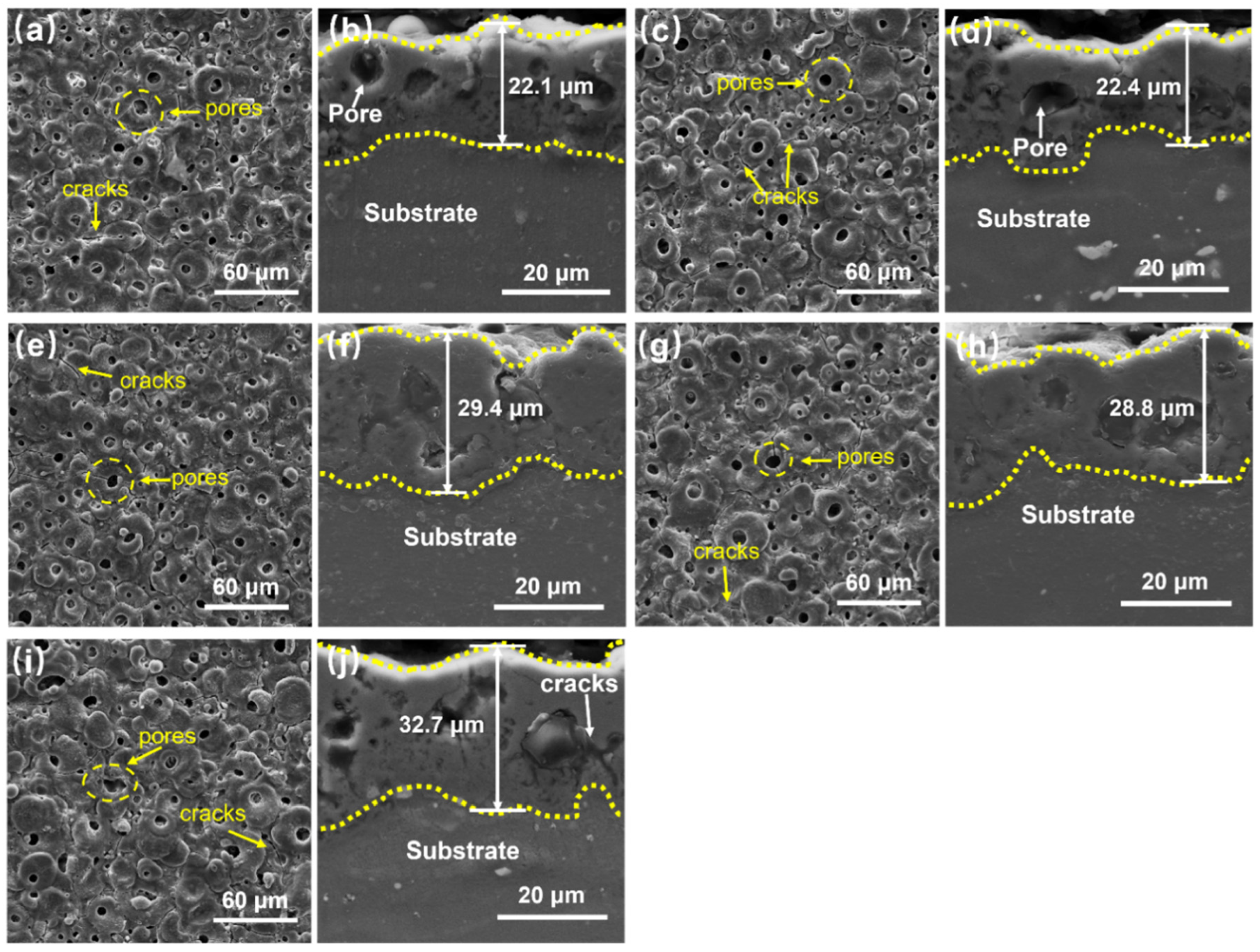
The surface micro-morphologies of the MAO coatings formed on the magnesium alloys processed under different friction stir processing conditions are shown in Figure 2. The coatings produced under different welding parameters exhibited similar microstructural characteristics. Like many previous studies, the micro-arc oxidation coatings prepared in this paper all featured a uniformly porous surface with pore diameters of approximately 3–5 μm. All MAO coatings showed the typical “volcanic crater” morphology commonly associated with micro-arc oxidation surfaces [34], accompanied by the presence of microcracks. The formation of micropores was mainly associated with the escape of gas bubbles and the breakdown channels created by spark discharges during the MAO process. Under high temperature and pressure, the molten oxides produced by these discharges were expelled from the discharge channels and subsequently accumulated on the surface, leading to the development of crater-like structures. In addition, rapid cooling provided by the water-cooling system caused thermal shock during solidification, which in turn promoted the formation of microcracks within the coating [36,37]. In addition, two typical types of surface micropores were observed on the MAO coatings formed under different welding conditions. The first type, referred to as the “hole-in-hole” structure shown in Figure 2, was produced by repeated dielectric breakdown. This feature mainly originated from in situ spark discharge events. During the early stage of the discharge process, the MAO reaction occurred primarily inside the discharge channel, where the molten products were expelled and accumulated around the channel edges. The deposition of these oxides gradually thickened the surrounding coating region, making subsequent breakdown more difficult [38]. As the spark discharge continues, secondary in situ breakdown tends to occur within pre-existing weak pores [39], leading to the formation of the “hole-in-hole” morphology. The second type was identified as a “repaired blind-hole” structure, which differed slightly from the first one. After the formation of initial discharge pores, the molten oxides generated during subsequent discharges could partially fill the existing pores, thereby increasing local resistance and suppressing further MAO reactions. As a result, the discharge sparks tended to migrate toward neighboring weak regions, where they sealed the previously formed pores and left only shallow openings on the surface, producing the so-called “repaired blind-hole” morphology. These two pore-growth mechanisms occurred simultaneously during the MAO process and are also innovative conclusions verified through numerous experiments conducted by the research group. Although spark discharge breakdown took place repeatedly, the molten zones and surrounding micropores still exhibited disk-like features. At the beginning of the process, the molten ceramic oxides primarily spread laterally, leading to the formation of island-shaped surface structures [40,41]. As the MAO discharge intensified, the rising thermal energy promoted the outward ejection and diffusion of molten oxides from the discharge channels, leading to oxide accumulation around nearby pores. This process enhanced the interaction between adjacent islands and gradually facilitated their sintering and coalescence, ultimately giving rise to the formation of a porous MAO coating.
As shown in the cross-sectional images, metallurgical bonding was achieved between the coatings and the magnesium alloy substrates. The interfaces exhibited an undulating, wave-like morphology, suggesting strong adhesion between the two layers. The coating thicknesses obtained under different processing parameters were generally consistent, with an average value of approximately 30 μm. Slightly thicker coatings, reaching about 35 μm, were produced under the S1500-3, S1500-5, and S1700-3 conditions. A few blind pores and microcracks were observed within the coatings; these defects were discontinuously distributed and did not extend to the substrate. Further comparison of the cross-sectional microstructural characteristics of the coatings prepared under different process conditions reveals that when the substrate was processed with S1500-3 and S1500-5 passes, the coatings exhibited smaller pore sizes, a significant reduction in defect count, uniform thickness distribution, and high overall surface flatness, demonstrating excellent compactness and structural integrity. This indicates that optimized FSP can effectively improve the surface microstructure uniformity of magnesium alloys and enhance the stability of discharge behavior during MAO, thereby facilitating the formation of a denser ceramic coating. In contrast, under the S1300-3 and S1500-1 pass conditions, the coatings showed relatively larger pores and an increased number of defects, with a corresponding decrease in compactness. This phenomenon suggests that insufficient thermo-mechanical coupling effect of FSP at low pass counts or low rotational speeds fails to provide a stable interfacial condition for subsequent coating growth. Although the coating obtained under the S1700-3 pass condition was thicker, it contained a higher density of microcracks. This indicates that under high heat input and stress, the coating is more prone to brittle cracking, which may adversely affect its overall corrosion resistance. In summary, variations in the substrate’s FSP parameters result in subtle differences in the microstructure and defects of the subsequent MAO coatings. Among all tested conditions, the coatings prepared on substrates processed with S1500-3 and S1500-5 passes exhibit a denser structure with fewer defects, laying a solid foundation for improving the corrosion resistance and service performance of the coatings in subsequent applications.

3.2. Phase and Elemental Analysis of MAO Coating

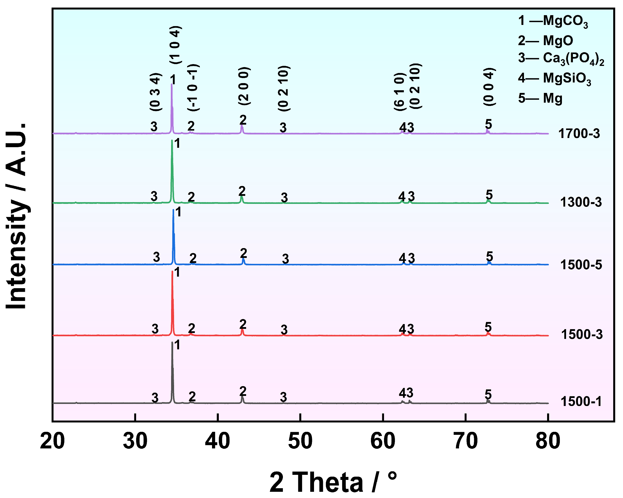
As observed in Figure 3, the phase compositions of the coatings obtained under the five FSP parameters were essentially similar, consisting mainly of Ca3(PO4)2, MgCO3, Mg, MgSiO3, and MgO. Among these, Mg2SiO3 and MgO were the dominant phases in all coatings. Generally, when the electrolyte contains silicate and phosphate components, MgO becomes the primary phase after MAO. Under spark discharge, H2O decomposes into H2 and OH, followed by further decomposition of OH into O2; the reaction between Mg and O2 results in the formation of MgO. The high melting point and high electrical resistivity of MgO contribute to the excellent thermal stability and corrosion resistance of the coating. Moreover, MgO exhibits good biocompatibility and causes minimal irritation to human tissue, endowing the MAO coatings on magnesium alloys with great potential as biomedical implant materials. It can enhance corrosion resistance and delay degradation while maintaining biosafety. The Mg2SiO3 phase forms when Mg2+ ions from the substrate diffuse outward and react with SiO32− ions in the electrolyte under the influence of a strong electric field. Similar to MgO, Mg2SiO3 exhibits high hardness and excellent corrosion resistance. The molten Mg2SiO3 formed during high-temperature oxidation possesses good fluidity, allowing it to penetrate and fill the micropores and microcracks within the MAO coating during rapid solidification, thereby enhancing coating compactness. Magnesium silicate can also release bioactive SiO34− ions in simulated body fluid, which stimulate osteoblast proliferation, differentiation, and mineralization. Owing to the high hardness of both MgO and Mg2SiO3, their combined presence produces a synergistic strengthening effect that markedly improves the hardness and wear resistance of the coating. This enhancement not only helps resist surface scratches and abrasion but also promotes better osseointegration and slows the degradation rate. In addition, Ca3(PO4)2 within the MAO layer can induce the deposition of Ca2+ and PO43− ions from body fluids onto the surface, facilitating new bone formation.
To further quantitatively characterize the structural features of the coating, this study employed the peak area integration method to calculate the crystallinity of the main phases. The results showed significant differences in the degree of crystallinity among the various phases. Specifically, the crystallinity values of Ca3(PO4)2, Mg, and MgO were 98.86%, 93.01%, and 98.02%, respectively, all approaching a highly crystalline state. This indicates that these phases underwent sufficient high-temperature melting and oriented crystallization during the micro-arc discharge process, resulting in well-developed crystal grains. The crystallinity of MgSiO3 reached 95.23%, demonstrating that the silicate structure also exhibits strong crystallization ability under the high-temperature environment of the discharge channel. In summary, all main ceramic phases in the coating exhibited high crystallinity, which suggests that the instantaneous high temperature and rapid cooling during the MAO process promoted the formation and refinement of the crystal structure. Unlike the aforementioned phases, the crystallinity of MgCO3 was only 42.22%, yet its diffraction peak was the strongest in the entire spectrum. This indicates that MgCO3 has a relatively high content and is one of the important constituent phases in the coating. The phenomenon of “high peak intensity but low crystallinity” is mainly related to the poor thermal stability of MgCO3. During the MAO process, carbonates may undergo partial decomposition and structural reorganization under high temperature and discharge impact, making it difficult for their crystals to develop completely and thus forming a large number of semi-crystalline or nanocrystalline regions. Such low-crystallinity phases can play a structural buffering role to a certain extent, which is beneficial for the coating to release thermal stress and may also improve its local toughness. Additionally, during the MAO process, the magnesium substrate undergoes local melting around the discharge pores, followed by rapid solidification. This process not only enables Mg to exhibit a relatively high degree of crystallization (93.01%) but also helps enhance the bonding between the coating and the matrix, improving the overall structural stability. As a result, MAO coatings on magnesium alloys demonstrate excellent corrosion resistance and biocompatibility, highlighting their strong potential for biomedical applications.
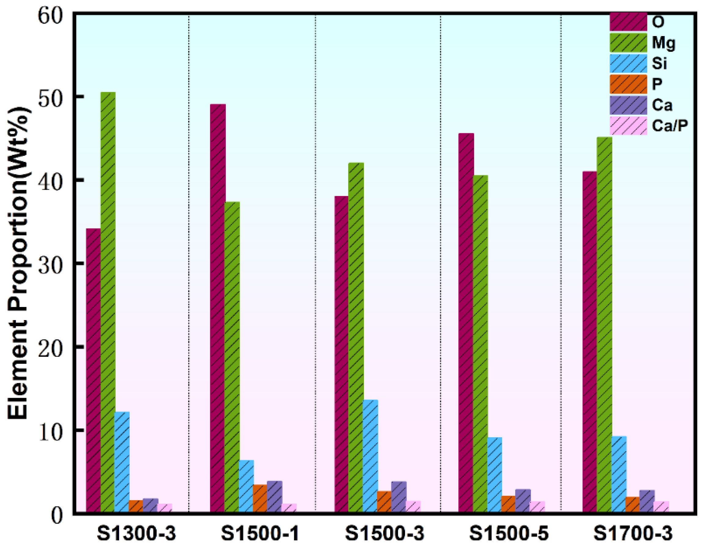
Figure 4 and Table 3 show that, in the elemental composition of the MAO coatings (examined by SEM), O, Mg, and Si were the predominant elements in the coatings, with relatively high concentrations. The Ca and P contents in the coatings were lower than those of O, Mg, and Si; however, their proportions varied with the processing parameters. The RCa/P of the coatings formed under the S1300-3 and S1500-1 conditions were relatively low, whereas those obtained under the S1500-3, S1500-5, and S1700-3 conditions exhibited higher RCa/P, reaching up to 1.44. This value is close to that of natural human bone (RCa/P ≈ 1.67) and significantly higher than the RCa/P of the MAO coating formed on the as-cast ZK60 magnesium alloy substrate without FSP treatment [42]. The RCa/P is considered an important indicator of the biological performance of coatings. The closer the RCa/P is to that of human bone, the better the coating can support osteoblast adhesion and growth on the implant surface [43]. The MAO coatings exhibited RCa/P close to that of natural bone, although they remained slightly lower than the value measured for the substrate (1.61). Higher Ca/P ratios were obtained for the coatings prepared under the S1500-3, S1500-5, and S1700-3 conditions, which is likely related to the improved dispersion of HA particles within the matrix as both stirring speed and the number of FSP passes increased. The more uniformly distributed HA in the substrate promoted the release of Ca2+ and PO43− ions during the MAO process, facilitating the formation of Ca–P compounds and thereby increasing the RCa/P in the coatings. Therefore, it can be concluded that the MAO coating formed on the magnesium alloy processed under the S1500-3 condition exhibited the highest Ca/P ratio among all samples, indicating superior biological performance. This coating can effectively induce osteoblast growth on its surface [44].
Since the peaks of Ca and P elements detected by XRD are relatively low, and the content of Ca and P elements shown in Table 3 is also low, XPS analysis was performed to further identify the chemical states of Ca and P on the MAO coating on the magnesium alloy processed under the S1500-3 condition, as shown in Figure 5. Figure 5a presents the survey spectrum of the coating, in which the characteristic peaks of P 2p, Ca 2p, O 1s, and Mg 1s were detected. According to the Mg 1s spectrum in Figure 5b, both MgO and metallic Mg were identified on the coating surface, with binding energies of 1303.88 eV and 1299.68 eV, respectively. The O 1s spectrum shown in Figure 5c indicates the presence of MgO and MgCO3, whose characteristic peaks were located at 531.18 eV and 531.98 eV, respectively. As shown in Figure 5d, the P 2p spectrum reveals the presence of metal phosphides and metal phosphates in the coating. Combined with the XRD results, the metal phosphate can be confirmed as Ca3(PO4)2, corresponding to a binding energy of 134.18 eV, while the metal phosphide peak appeared at 133.18 eV. The Ca 2p spectrum in Figure 5e further confirms the existence of Ca3(PO4)2 and CaCO3, with their characteristic peaks located at 351.28 eV and 347.28 eV, respectively. Based on the XPS analysis, five phases—MgO, MgCO3, Ca3(PO4)2, CaCO3, and metal phosphate—were identified in the MAO coating. Combined with the XRD phase analysis, the metal phosphate can be determined as Ca3(PO4)2. Therefore, the MAO coating on the S1500-3 FSP-processed magnesium alloy consisted of five major phases: Ca3(PO4)2, CaCO3, Mg, Mg2SiO3, MgO, and Ca2P2O7.

3.3. Properties of MAO Coating

3.3.1. Surface Roughness of MAO Coating

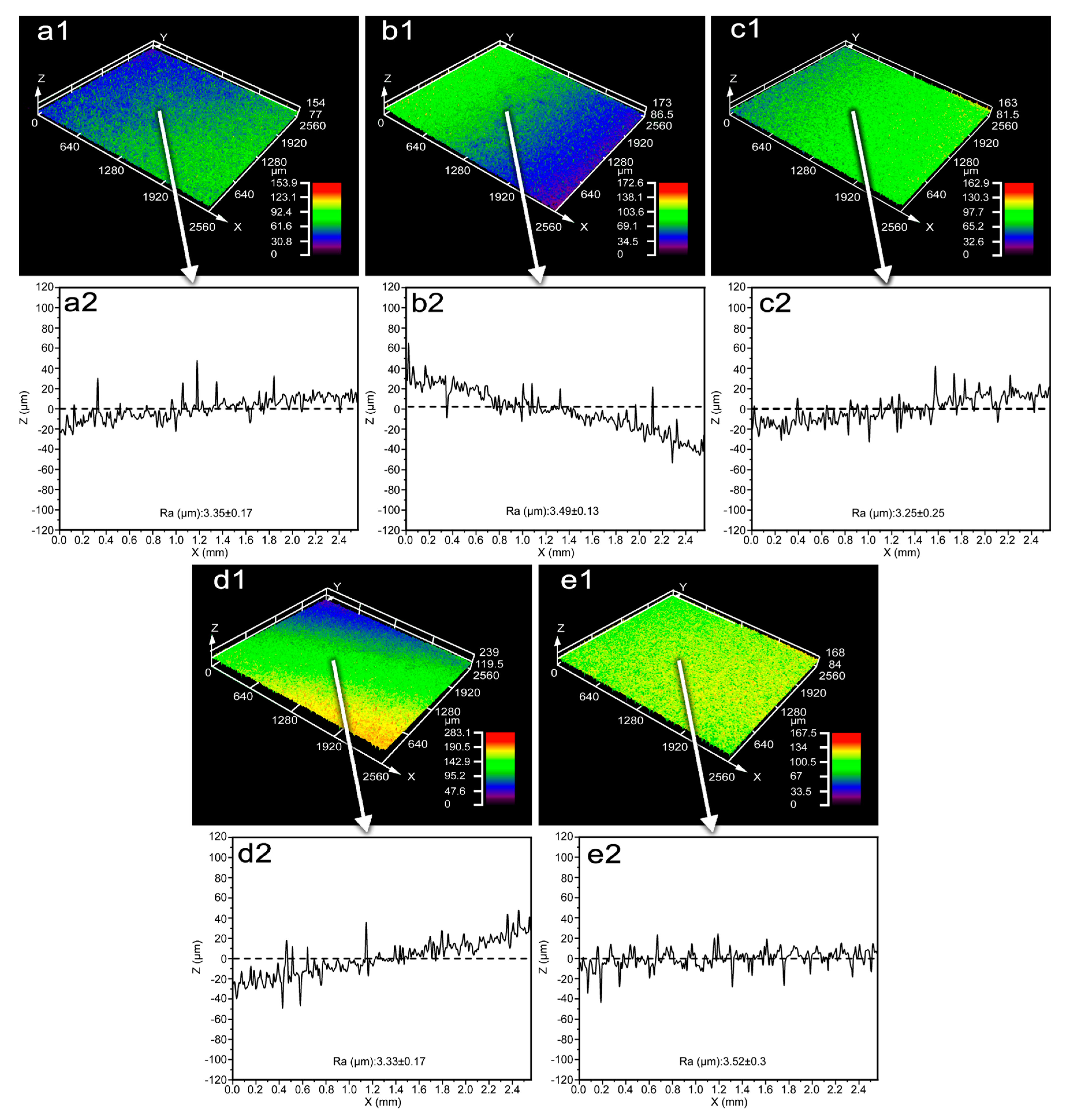
The surface roughness of MAO coatings on magnesium alloys processed by five different techniques was measured using an Olympus laser confocal microscope, and the test results are presented in Figure 6. To ensure the reliability of the test data, five distinct characteristic regions were selected on the surface of each specimen. Within each region, one test line was arranged perpendicular to the FSP direction, resulting in a total of five valid test lines per specimen. The line roughness (Ra) of each test line was calculated using the analytical software integrated with the instrument, and the arithmetic mean of the five line roughness values was adopted as the final roughness data for the MAO coating of the corresponding specimen. This approach effectively avoids accidental errors caused by single test points. As clearly illustrated in the roughness statistical results in Figure 6, the roughness values of the MAO coatings corresponding to the five different processed substrates are all within the same order of magnitude, with slight numerical differences. Among them, the magnesium alloy substrate treated by the S1700-3 process exhibits the highest roughness, with an average coating roughness (Ra) of 3.52 μm, while the specimen processed by the S1500-3 process shows the lowest roughness, with an average coating roughness of 3.25 μm. The difference in roughness between the two is merely 0.27 μm. This result indicates that within the range of welding process parameters set in this experiment, different FSP techniques exert no significant influence on the surface roughness of the MAO coatings, which is well consistent with the uniform and dense macroscopic morphology of the coatings shown in Figure 1. It can also be observed from the surface microtopography of the coatings in Figure 2 that all MAO coatings corresponding to the five processes exhibit typical structural characteristics: uniformly distributed micro-pores of similar sizes, slightly dispersed microcracks, and traces of minor molten substance accumulation. Additionally, no obvious local protrusions, depressions, or large-area irregular undulations are found on the coating surfaces, which generally present a uniform and flat microstate. It is the consistency in this microstructure that leads to the slight differences in the macroscopic roughness values among the various coatings, further verifying the conclusion that FSP techniques have little impact on coating roughness.
Furthermore, the 3D topography diagrams of the coatings attached in Figure 6 more intuitively demonstrate the surface undulation characteristics of the coatings under different processes. Compared with the other three processes, the MAO coatings obtained by the S1500-3 pass and S1700-3 pass processes exhibit slightly smaller heights of surface protrusions, depths of depressions, and fluctuation amplitudes of overall undulations, showing relatively better surface flatness. However, this difference is still negligible and does not alter the core conclusion that “different FSP techniques have no significant effect on coating roughness.” Combined with the results of coating microtopography observation and 3D topography analysis, it can be concluded that adjusting the FSP parameters has a limited regulatory effect on the surface roughness of MAO coatings. Instead, the coating roughness is mainly dominated by inherent reaction mechanisms during the MAO process, such as discharge ablation and melting-cooling.

3.3.2. Wear Resistance of MAO Coating

For metallic biomedical implants, wear resistance is a key factor that directly determines their long-term safety, functional stability, and biological compatibility. As a bone implant material, adequate wear resistance is indispensable; insufficient resistance can lead to impaired bone healing and even cause secondary injury. Friction between the implant and the surrounding tissues may also generate wear debris, which disrupts the bonding between the implant and the bone matrix. The accumulation of such particles can induce aseptic loosening and eventually lead to implant failure. Nevertheless, excessive hardness is not always beneficial. When an implant is overly wear-resistant, the increased friction against bone during motion can damage adjacent tissues and trigger secondary trauma. For joint replacement implants in particular, high wear resistance remains crucial, as these components must endure tens of thousands of cyclic loads and repeated frictional contacts throughout their service life [45,46]. In contrast, non-articulating implants have relatively lower wear-resistance requirements, but the material must still avoid generating wear particles that could induce inflammation, osteolysis, or other adverse biological reactions. Therefore, the wear resistance of MAO coatings produced under different processing conditions was investigated in this study.
According to the phase analysis discussed above, MgO and Mg2SiO3 were identified as the main components of MAO coatings. Both phases possess high hardness, and their synergistic effect can significantly enhance the hardness and wear resistance of the magnesium alloy, effectively protecting the surface from scratching and abrasion. The two phases form a multiphase composite structure in the MAO coating, which not only exerts a dispersion strengthening effect but also significantly enhances the hardness and resistance to plastic deformation of the surface material by impeding dislocation motion and microcrack propagation. Consequently, the service performance of magnesium alloys under contact fatigue and sliding wear conditions is effectively improved.
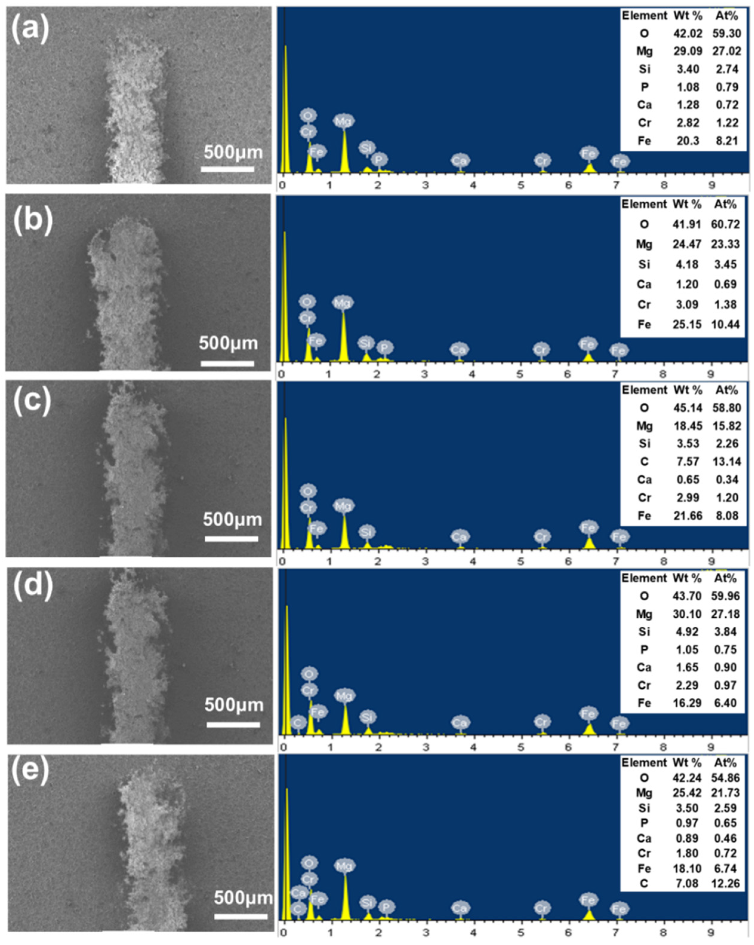
As shown in Figure 7, the wear morphologies and elemental analyses indicate that a considerable amount of Fe was detected on the worn surfaces. The Fe originated from the steel-ball counterbody used during the wear tests. The adhesion of Fe to the coating surface suggests that mutual wear occurred between the steel ball and the coating during sliding. The Fe element transfer mechanism can be attributed to adhesive wear induced by the combined effect of local high contact stress and transient frictional heat. During cyclic sliding, plastic deformation and local welding occur between microasperities, resulting in the transfer of steel ball material to the ceramic coating surface in the form of micron-scale particles. This constitutes a typical material transfer behavior in three-body wear. Moreover, the contents of Mg, Ca, P, and Si decreased after the wear test, indicating that MgO, Mg2SiO3, and other constituents of the coating were transferred and adhered to the steel ball surface during the wear process. This indicates that the main phases in the coating, including MgO, MgCO3, and ceramic phases containing Ca and P, underwent mechanical spallation, brittle fracture, or tribochemical reactions during the friction process. Some of these phases were transferred and reversely adhered to the surface of the counterbody steel ball, forming a light-colored transfer film. This phenomenon suggests that under the test conditions, the wear mechanism of the coating surface involves not only mechanical removal processes such as brittle spallation and abrasive wear but also significant tribochemical behaviors. Under the coupling effect of frictional heat and contact stress, the surface layer material may undergo non-equilibrium phase transformation, accelerated oxidation, or even decomposition reactions, thereby accelerating material loss. During the friction process, the MAO coating protects the magnesium alloy substrate through its own wear and material transfer. Its high hardness and multiphase composite structure effectively inhibit the further propagation of wear, demonstrating excellent wear resistance and a potential energy dissipation mechanism. As shown in Figure 8, the wear volume of the coatings conditions varied only slightly after 10 min of testing, ranging from approximately 2.3 × 10⁵ to 3.0 × 105 μm3. The coating prepared under the S1300-3 condition exhibited the highest wear volume of 3.05 × 105 μm3, whereas the coating produced under the S1500-3 condition had the lowest wear volume of 2.37 × 105 μm3, demonstrating superior wear resistance among the five coatings.

3.3.3. Elastic Modulus and Adhesion Strength of MAO Coating

Biomedical implant materials require their elastic modulus to be as close as possible to that of the replaced bone tissue to minimize the “stress shielding effect”. If the elastic modulus of the implant (especially load-bearing implants such as bone plates, intramedullary nails, and joint stems is much higher than that of human cortical bone (clinically recognized cortical bone elastic modulus ranges from approximately 10–30 GPa), during the process of bearing mechanical loads after implantation, the stiffer implant will become the main carrier of mechanical loads, thereby significantly diverting the stress that should originally be borne by the bone tissue. This redistribution of stress transmission will cause the bone tissue under and around the implant to be in a low-stress stimulation environment for a long time. Long-term lack of sufficient stress will trigger a metabolic imbalance where bone resorption exceeds bone formation, ultimately manifesting as decreased bone density, atrophy of trabecular bone, and gradual weakening of the bony support structure around the implant. With the decline in bone support capacity, the interfacial bonding strength between the implant and bone tissue will continue to decrease, which in turn leads to implant loosening and displacement. In severe cases, it may even cause implant fracture or surrounding bone fracture due to local stress concentration, directly affecting the therapeutic effect of implantation surgery and the long-term quality of life of patients. From the perspective of ideal design goals, the elastic modulus of the implant should achieve complete matching with bone tissue to ensure uniform transmission of mechanical loads between the implant and bone tissue, which not only avoids the stress shielding effect but also provides the mechanical stimulation required for bone tissue to maintain its normal physiological functions. However, currently clinically used medical metal materials all have the problem of excessively high elastic modulus. Among them, the elastic modulus of 316L medical stainless steel is as high as 200 GPa, the elastic modulus of Co-Cr alloy is as high as 250 GPa, which are far beyond the mechanical adaptation range of bone tissue and cannot meet the modulus requirements of ideal implant materials [47]. Hence, developing materials with lower elastic modulus is a primary approach to mitigating the stress-shielding effect.
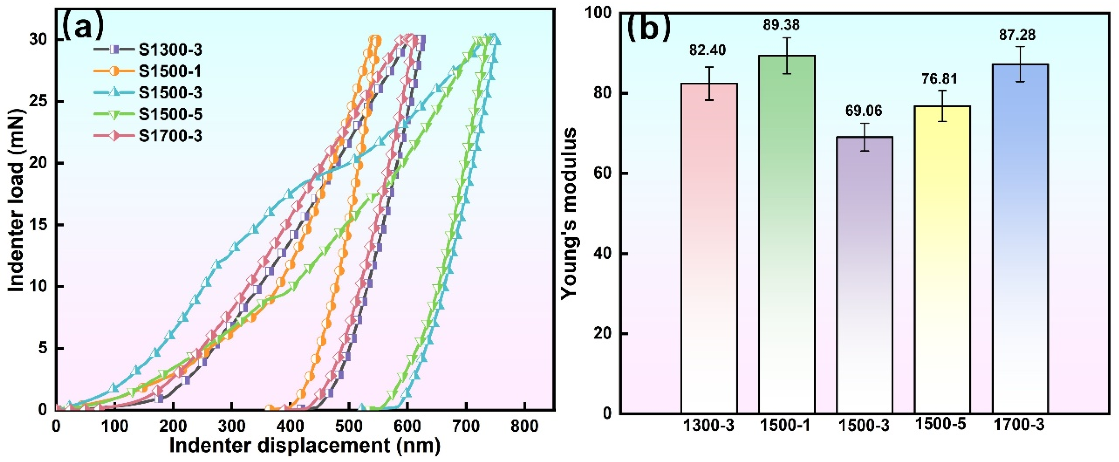
In this study, since the thickness of the coating is usually at the micrometer level, which is much lower than the applicable test range of universal hardness testers, the use of traditional mechanical property testing methods not only makes it difficult to obtain accurate hardness data but also may cause coating cracking or peeling from the substrate due to excessive test load, failing to truly reflect the mechanical properties of the coating itself. Based on this, this paper adopts nanoindentation technology to test the hardness of different coatings, realizing accurate characterization of the coating’s hardness and elastic modulus without damaging the coating structure. After obtaining the load–displacement curves of the coatings through nanoindentation experiments, the experimental data were analyzed in combination with the Oliver-Pharr calculation model to convert and obtain the elastic modulus of each coating. The finally derived test results of the coating elastic modulus are shown in Figure 9. In previous work by our team, it was found that when fabricating Mg/HA composites via FSP, among the five welding parameters tested, the S1500-3 FSP process resulted in uniform distribution of HA powder within the alloy, significant grain refinement, and the formation of a weak texture. The elastic modulus of the alloy under this process was measured at 32.08 GPa, which is highly close to that of human bone. Under other processing conditions, the elastic modulus ranged from 32.75 to 37.91 GPa, also remaining at a relatively low level. Therefore, depositing a bio-coating on the surface of the treated alloy can further reduce the material’s elastic modulus. As shown in Figure 9b, all MAO coatings exhibited elastic moduli below 100 GPa, ranging from 69 to 90 GPa, which are slightly higher than that of natural bone tissue. Among them, the coating prepared on the magnesium alloy processed under the S1500-3 condition exhibited the lowest elastic modulus of 69.06 GPa, making it the closest to that of human bone among all samples.
As shown in Figure 10a, the PD curve represents the probe penetration depth during the scratching process, while the AE curve corresponds to the acoustic emission signals recorded simultaneously. Owing to the porous and relatively loose microstructure of the MAO coatings, the acoustic emission signals fluctuated continuously throughout the test. This behavior differs from that of brittle coatings, which typically exhibit a sharp and pronounced AE peak upon cracking or delamination [29,48]. In this study, the adhesion strength was determined based on the microscopic morphology of the coating at the moment when the probe penetrated the coating. As indicated at point (A) in the lower part of the image, the coating surface changed from gray to bright white, suggesting that the probe had reached the coating–substrate interface and the coating began to rupture. The critical load applied by the indenter at the onset of coating failure was defined as Lc. A higher Lc value indicates better coating adhesion, and thus Lc was used to characterize the adhesion strength of the MAO coatings.
By comparing the adhesion strength of the five MAO coatings, it was found that the coatings prepared under the S1300-3, S1500-1, and S1700-3 processing conditions exhibited relatively low adhesion strength, ranging from approximately 10.5 to 11.5 N. As can be observed from Figure 2, the coatings were thinner and contained microdefects such as pores and microcracks, which likely contributed to their reduced adhesion strength. In contrast, the coatings formed on the substrates processed under the S1500-3 and S1500-5 conditions exhibited more uniform and compact structures with fewer pores and cracks, resulting in significantly improved adhesion strength. Among them, the coating obtained under the S1500-3 condition demonstrated the highest adhesion strength of 14.485 N, as shown in Figure 10.
Compared with the MAO coating prepared on the surface of the magnesium alloy without FSP, the bonding strength is significantly improved, increasing from 8.75 N to 14.485 N, with an approximate increase of 60%, as shown in Figure 10f. The difference between the two coatings lies in the different substrates, it can be concluded that when the MAO reaction is carried out with the Mg/HA magnesium matrix composite as the substrate, on one hand, the elements in the electrolyte react on the surface of the magnesium alloy to form Ca-P compounds; on the other hand, the Ca and P elements provided by the uniformly distributed HA powder in the substrate undergo mass transfer from the substrate to the surface through the electric spark breakdown channels to form a Ca-P compound. As a result, a large number of chemical reactions occur at the interface, resulting in significant improvements in both the coating’s adhesion and biological properties.

3.3.4. Corrosion Resistance of MAO Coating

Studies have shown that after the coating is immersed in corrosive media, such as simulated body fluid and seawater for a certain period of time, the corrosive media will penetrate into the interior of the coating through the micro-pores on the surface. Moreover, the interior of the coating has typical structures such as “pore-in-pore” and microcracks; therefore, the corrosive media can seep into the coating interior along these micro-pores and cracks. At this point, corrosion occurs simultaneously on the surface and inside of the coating. The corrosion process of the coating starts with pitting corrosion, after the corrosion pits expand, they connect with each other, forming large-area corrosion. Meanwhile, the hydrogen gas generated during the corrosion reaction and massive corrosion products will accumulate inside the coating and at the interface, generating significant internal stress. This ultimately leads to the peeling off of the film layer, causing it to lose its protective effect on the substrate [49].
The electrochemical test results of the five coatings in this work are shown in Figure 11. The corrosion resistance of the coatings can be directly reflected by the diameter of the capacitive reactance arc in the Nyquist plot of Figure 11a, the Bode plot in Figure 11b is helpful for analyzing the uniformity and protection efficiency of the coatings. Table 4 presents the specific values obtained by fitting the experimental data in Figure 11 based on the equivalent circuit model, which provides a basis for the accurate analysis of the corrosion resistance of different coatings. When constructing the equivalent circuit model, in order to more accurately describe the electrochemical behavior of the coating system, this study uses a Constant Phase Element (CPE) to replace the ideal capacitor element. This treatment is based on the non-ideal capacitive behavior caused by the surface inhomogeneity of the coating, the existence of micro-defects, and the dispersion effect of current distribution, and this method is a widely recognized standard practice in this field [50,51]. Among the parameters, Rs represents the resistance of the Hank’s solution, Rc is connected in parallel with CPEc, which together describe the resistance and capacitance characteristics of the coating. Rct is connected in parallel with CPEct, which is used to simulate the charge transfer process at the metal/solution interface. Among all parameters, the charge transfer resistance (Rct) is a key indicator for evaluating the overall corrosion resistance of the film layer. A larger Rct value indicates greater resistance to corrosive ions passing through the film layer to reach the substrate and undergo electrochemical reactions; therefore, the corrosion resistance of the sample is usually more excellent [52,53].
The microstructure of the microarc oxidation coating directly influences its corrosion resistance performance, including both coating thickness and compactness. A dense coating with smaller pore sizes, fewer microcracks, and greater thickness can effectively improve corrosion resistance [54]. As shown in the impedance spectra in Figure 11 and the fitted data in Table 4, all five coatings exhibited impedance values on the order of 104 Ω·cm2, which is one to two magnitudes higher than that of substrate. The slight differences in impedance among the five samples indicate that variations in the FSP parameters influenced the substrate microstructure more strongly than the MAO coating itself. Consistent with the cross-sectional morphologies in Figure 2, the coating fabricated under the S1500-1 condition displayed relatively large microcracks and reduced thickness. A thinner coating with larger pores increases the probability of corrosive medium penetration, allowing direct attack on the substrate and resulting in inferior corrosion protection. Consequently, this coating showed the lowest corrosion resistance, with an R2 value of 1.03 × 10⁴ Ω·cm2. In contrast, the coatings formed on S1500-3, S1500-5, and S1700-3 conditions exhibited more uniform and compact cross-sectional morphologies with greater thickness, leading to superior corrosion resistance. Among them, the coating obtained under the S1500-3 condition showed the highest impedance value of 2.22 × 10⁴ Ω·cm2. As confirmed by the microstructural observations in Figure 2, this coating had the smallest number of pores and cracks as well as the greatest effective thickness, thereby exhibiting the best corrosion resistance among all samples.

3.3.5. Wettability and Antibacterial Properties of MAO Coating

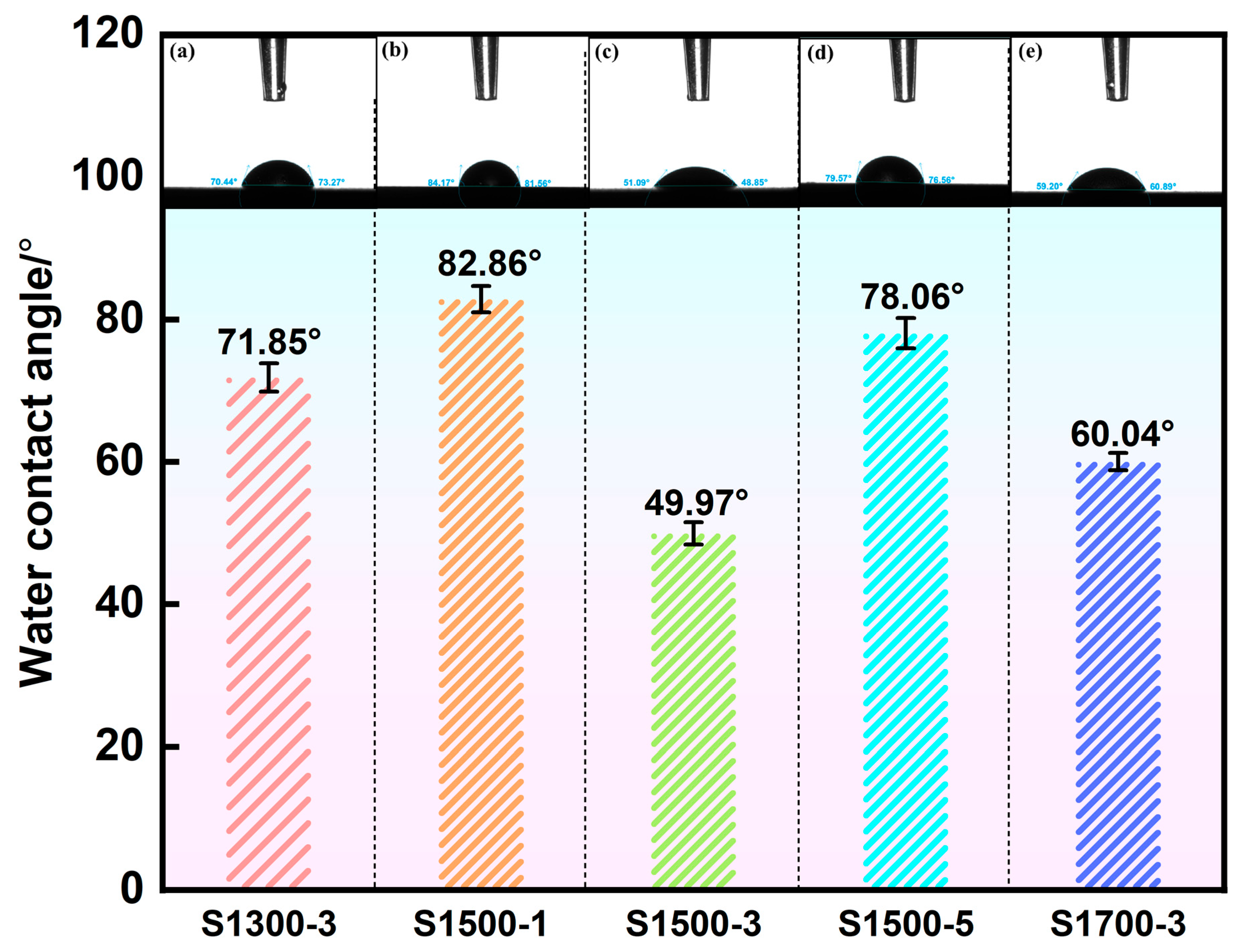
For the success of any biomedical implant device, cell adhesion, proliferation, and differentiation are among the most critical processes, which fundamentally depend on the physical and chemical properties of the implant surface [55,56]. Cellular activity is strongly influenced by surface roughness, contact angle, morphology, and composition [57]. Wettability is a key parameter for evaluating the biocompatibility of biomedical materials. In general, hydrophilic surfaces promote better cell adhesion and spreading, since most mammalian cells adhere more readily to moderately hydrophilic surfaces, where the contact angle typically ranges between 40° and 70° [58,59]. Conversely, surfaces that are either excessively hydrophobic (θ > 90°) or extremely hydrophilic (θ < 10°) tend to hinder the initial adhesion and spreading of cells, although the optimal contact angle may vary depending on the specific cell type. Generally, moderately hydrophilic surfaces are associated with more favorable biological responses, including reduced nonspecific protein adsorption, enhanced cell adhesion, spreading, proliferation, and differentiation, as well as improved hemocompatibility and stronger resistance to bacterial attachment [58,60]. The contact angles of the MAO coatings and the corresponding results are shown in Figure 12. The measured values ranged from approximately 50° to 80°, reflecting the influence of surface morphology, such as the presence of micropores, microcracks, and molten regions. All coatings displayed contact angles below 90°, confirming their hydrophilic nature. Notably, the coatings produced under the S1500-3 and S1700-3 conditions exhibited contact angles of 48.85° and 59.20°, respectively, which fall within the range of moderate hydrophilicity.
As a bone implant material designed for in vivo applications, the MAO coating must not only present a hydrophilic surface but also possess effective antibacterial activity, both of which are essential for clinical safety. Although thorough sterilization of implants before surgery is necessary, postoperative inflammation and infection still remain difficult to eliminate. Such biomaterial-associated infections are primarily attributed to the formation of bacterial biocoatings on the implant surface [61,62], which can shield bacteria from attacks by the immune system and antibiotics, leading to severe degradation of the implant. Therefore, implants should possess intrinsic antibacterial capability to inhibit or prevent biocoating formation. In this study, the antibacterial performance of the coatings was assessed using E. coli as the model bacterium.
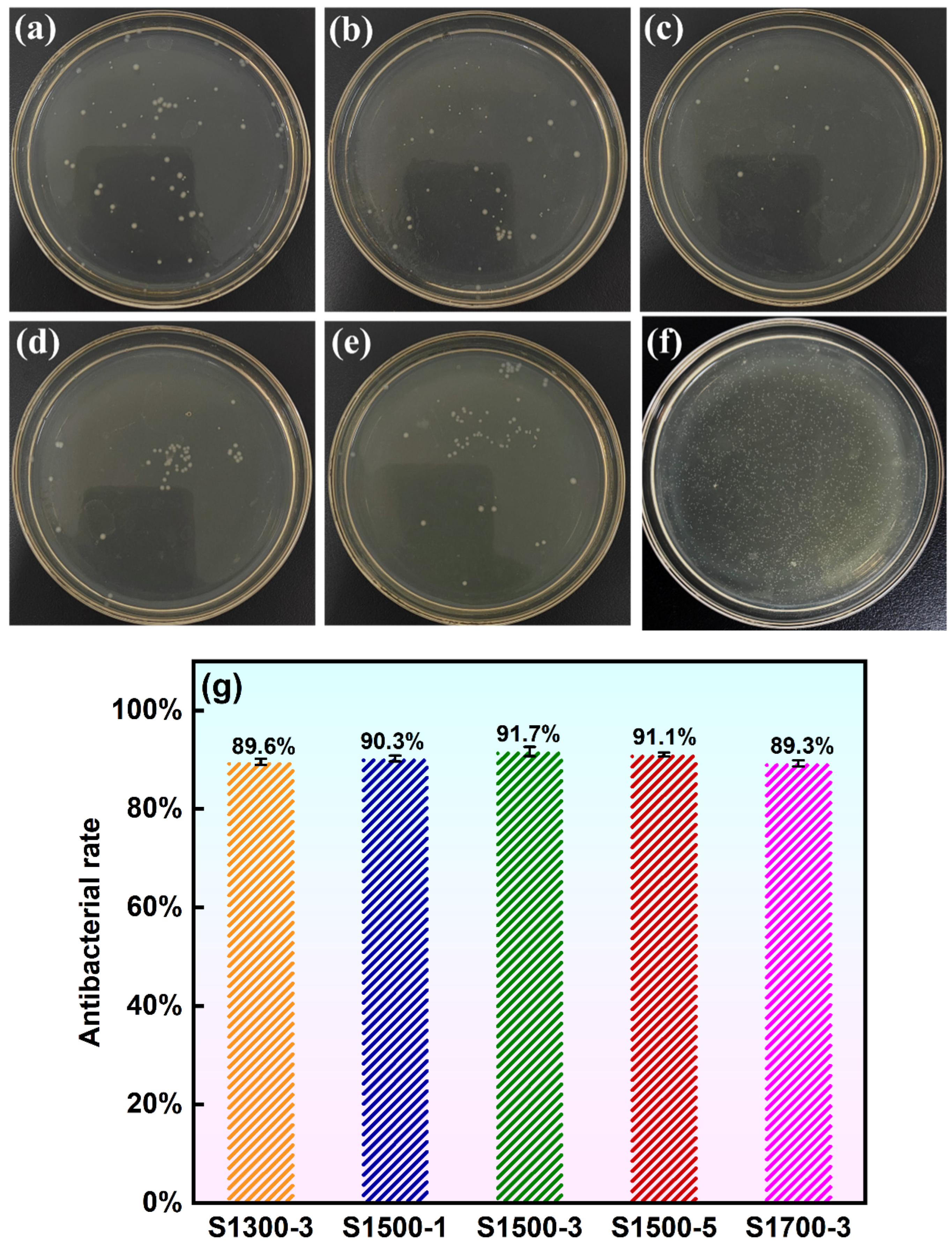
Figure 13 presents the bacterial colony morphologies observed after antibacterial testing of the different MAO coatings. Since neither the substrate nor the coatings contained antibacterial ions, the overall antibacterial rates remained in the range of 89%–92%. Among the tested samples, the coatings produced on alloys processed under the S1500-3, S1500-5, and S1700-3 conditions exhibited slightly higher antibacterial activity, likely due to the presence of Ca–P compounds on the coating surface. These Ca–P phases have been reported to provide mild bacteriostatic effects, which may contribute to the observed improvement in antibacterial performance [63]. In particular, the coating prepared under the S1500-3 condition achieved an antibacterial rate of 91.7%, satisfying the criterion for short-term antibacterial effectiveness (≥90%). Overall, this coating demonstrated the most balanced and superior combination of characteristics among all processing conditions, showing excellent mechanical strength, corrosion resistance, hydrophilicity, and antibacterial performance.

4. Conclusions

In this study, Mg/HA composite magnesium alloys fabricated under different FSP conditions were employed as substrates for the preparation of MAO bio-coatings. The coatings were systematically characterized in terms of their macroscopic morphology, microstructure, phase composition, and elemental distribution. Their overall performance was further evaluated by examining mechanical behavior, corrosion and wear resistance, adhesion strength, and antibacterial activity. The main conclusions are summarized below:
  • All MAO coatings fabricated on the magnesium alloy substrates exhibited dense and uniform gray–white appearances. The surface microstructures were characterized by porous “volcanic crater” features with pore diameters of approximately 2.6–12 μm, containing two typical types of micropores, namely “pore-in-pore” and “repaired blind pore” structures, together with a few fine microcracks. Cross-sectional examination demonstrates excellent metallurgical bonding at the coating–substrate interface, with only a small number of blind pores and microcracks observed.
  • XRD analysis indicates that Ca3(PO4)2, CaCO3, Mg, Mg2SiO3, MgO, and Ca2P2O7 are the main phases of the coating. MgO and Mg2SiO3 phases form a multiphase composite structure in the MAO coating, enhancing the hardness and resistance to plastic deformation of the surface material by impeding dislocation motion and microcrack propagation. Elemental analysis showed that the coating formed under the S1500-3 condition had the highest RCa/P of 1.44. This indicates that the uniformly dispersed HA particles in the substrate promoted the release of Ca2+ and PO43− ions during the MAO process. The enhanced ion transport increased the Ca/P ratio in the coating, thereby improving its biological activity and promoting osteoblast adhesion and growth on the surface.
  • Performance evaluation showed that all MAO coatings possessed comparable surface roughness, with an average value of about 3.25 μm. The coatings exhibited excellent wear resistance and strong adhesion, with the highest adhesion strength reaching 14.485 N. In addition, all coatings demonstrated excellent corrosion resistance. Wettability and antibacterial tests further confirmed their hydrophilic nature, and the coatings produced under the S1500-3 and S1700-3 conditions exhibited moderate hydrophilicity, which is more conducive to cell adhesion and spreading during in vivo implantation. The antibacterial rate of the coatings reached as high as 91.7%, satisfying the short-term antibacterial criterion for biomedical implants.
  • Thus, the MAO coating formed on the substrate processed under the S1500-3 condition showed the most balanced and optimal performance, combining excellent mechanical integrity, corrosion resistance, hydrophilicity, and antibacterial activity. This study provides theoretical support for the application of biomedical magnesium alloys as in vivo implant materials and offers data backing for further advancing their clinical translation.

Author Contributions

Conceptualization, W.L., Z.W. and L.C.; Methodology, W.L., D.O. and L.C.; Software, S.L. and Y.Z.; Validation, Y.Z., J.M. and Z.X.; Investigation, W.L., Z.X. and J.M.; Resources, J.M. and D.O.; Data Curation, D.O.; Writing—Original Draft Preparation, W.L. and Z.X.; Writing—Review and Editing, Z.W.; Supervision, S.L.; Funding Acquisition, Z.W. and S.L. All authors have read and agreed to the published version of the manuscript.

Funding

This work was supported by the Jiangsu Province Foreign Experts Hundred Talents Program (BX2022030).

Data Availability Statement

The data that support the findings of this study are available from the corresponding author upon reasonable request.

Conflicts of Interest

The authors declare that they have no conflicts of interest.

References

  1. Rajendran, S.; Ranganathan, B.; Karuppasamy, K. Predictive Modeling and Optimization of Abrasive Waterjet Drilling (AWJD) Parameters on AZ31B-Mg Alloy using Neural Networks and Grey Relational Analysis. Rev. Metal. 2025, 60, e261. [Google Scholar] [CrossRef]
  2. Sharma, S.K.; Gajevic, S.; Sharma, L.K.; Pradhan, R.; Miladinovic, S.; Asonja, A.; Stojanovic, B. Magnesium-Titanium Alloys: A Promising Solution for Biodegradable Biomedical Implants. Materials 2024, 17, 5157. [Google Scholar] [CrossRef] [PubMed]
  3. Ma, Y.z.; Yang, C.l.; Liu, Y.j.; Yuan, F.s.; Liang, S.s.; Li, H.x.; Zhang, J.s. Microstructure, mechanical, and corrosion properties of extruded low-alloyed Mg-xZn-0.2Ca alloys. Int. J. Miner. Metall. Mater. 2019, 26, 1274–1284. [Google Scholar] [CrossRef]
  4. Eivani, A.R.; Tabatabaei, F.; Khavandi, A.R.; Tajabadi, M.; Mehdizade, M.; Jafarian, H.R.; Zhou, J. The effect of addition of hardystonite on the strength, ductility and corrosion resistance of WE43 magnesium alloy. J. Mater. Res. Technol. 2021, 13, 1855–1865. [Google Scholar] [CrossRef]
  5. Sharan Krishna, R.S.; Muhammad Rabeeh, V.P.; Rahim, S.A.; Joseph, M.A.; Hanas, T. Effect of grain refinement on biomineralization and biodegradation of Mg–Ca alloy. J. Mater. Res. 2023, 38, 4772–4783. [Google Scholar] [CrossRef]
  6. Johari, M.; Jabbari, A.H.; Sedighi, M. High cycle fatigue and corrosion behaviors of Mg3Zn/HA biodegradable composite. J. Mater. Res. Technol. 2024, 28, 695–706. [Google Scholar] [CrossRef]
  7. Liu, D.; Yang, D.; Li, X.; Hu, S. Mechanical properties, corrosion resistance and biocompatibilities of degradable Mg-RE alloys: A review. J. Mater. Res. Technol. 2019, 8, 1538–1549. [Google Scholar] [CrossRef]
  8. Garimella, A.; Bandhu Ghosh, S.; Bandyopadhyay-Ghosh, S. Composite bone-implant engineered with magnesium and variable degradation for orthopaedics. Mater. Today Proc. 2023, 28. [Google Scholar] [CrossRef]
  9. Zhang, D.; Zhou, J.; Peng, F.; Tan, J.; Zhang, X.; Qian, S.; Qiao, Y.; Zhang, Y.; Liu, X. Mg-Fe LDH sealed PEO coating on magnesium for biodegradation control, antibacteria and osteogenesis. J. Mater. Sci. Technol. 2022, 105, 57–67. [Google Scholar] [CrossRef]
  10. Wang, J.; Witte, F.; Xi, T.; Zheng, Y.; Yang, K.; Yang, Y.; Zhao, D.; Meng, J.; Li, Y.; Li, W.; et al. Recommendation for modifying current cytotoxicity testing standards for biodegradable magnesium-based materials. Acta Biomater. 2015, 21, 237–249. [Google Scholar] [CrossRef]
  11. Kumar, R.; Katyal, P. Effects of alloying elements on performance of biodegradable magnesium alloy. Mater. Today Proc. 2022, 56, 2443–2450. [Google Scholar] [CrossRef]
  12. Bairagi, D.; Mandal, S. A comprehensive review on biocompatible Mg-based alloys as temporary orthopaedic implants: Current status, challenges, and future prospects. J. Magnes. Alloys 2022, 10, 627–669. [Google Scholar] [CrossRef]
  13. Guo, L.; Yu, B.; Zhou, P.; Zhang, T.; Wang, F. Fabrication of low-cost Ni-P composite coating on Mg alloys with a significant improvement of corrosion resistance: Critical role of mitigating the galvanic contact between the substrate and the coating. Corros. Sci. 2021, 183, 109329. [Google Scholar] [CrossRef]
  14. Wong, H.M.; Zhao, Y.; Tam, V.; Wu, S.; Chu, P.K.; Zheng, Y.; To, M.K.T.; Leung, F.K.L.; Luk, K.D.K.; Cheung, K.M.C.; et al. In vivo stimulation of bone formation by aluminum and oxygen plasma surface-modified magnesium implants. Biomaterials 2013, 34, 9863–9876. [Google Scholar] [CrossRef] [PubMed]
  15. Campo, R.d.; Savoini, B.; Muñoz, A.; Monge, M.A.; Garcés, G. Mechanical properties and corrosion behavior of Mg–HAP composites. J. Mech. Behav. Biomed. Mater. 2014, 39, 238–246. [Google Scholar] [CrossRef] [PubMed]
  16. Khalajabadi, S.Z.; Abdul Kadir, M.R.; Izman, S.; Ebrahimi-Kahrizsangi, R. Fabrication, bio-corrosion behavior and mechanical properties of a Mg/HA/MgO nanocomposite for biomedical applications. Mater. Des. 2015, 88, 1223–1233. [Google Scholar] [CrossRef]
  17. Xiong, G.; Nie, Y.; Ji, D.; Li, J.; Li, C.; Li, W.; Zhu, Y.; Luo, H.; Wan, Y. Characterization of biomedical hydroxyapatite/magnesium composites prepared by powder metallurgy assisted with microwave sintering. Curr. Appl. Phys. 2016, 16, 830–836. [Google Scholar] [CrossRef]
  18. Zhao, Y.q.; Yang, H.k.; Andriia, A.; Lo, H.h.; Li, J.x. Refill friction stir spot welding (RFSSW): A review of processing, similar/dissimilar materials joining, mechanical properties and fracture mechanism. J. Iron Steel Res. Int. 2024, 31, 1825–1839. [Google Scholar] [CrossRef]
  19. Wu, D.c.; Wang, F.f.; Li, S.; Wang, W.q.; Wang, D.; Li, Y.l.; Miao, T. Microstructural and nanomechanical behavior of friction stir welded dissimilar joint of AA2219-T6/AA2195-T8 alloys. J. Iron Steel Res. Int. 2024, 31, 3080–3094. [Google Scholar] [CrossRef]
  20. Karageorgiou, V.; Kaplan, D. Porosity of 3D biomaterial scaffolds and osteogenesis. Biomaterials 2005, 26, 5474–5491. [Google Scholar] [CrossRef]
  21. Vandana, B.; Syamala, P.; Venugopal, D.S.; Sk, S.R.K.I.; Venkateswarlu, B.; Jagannatham, M.; Kolenčík, M.; Ramakanth, I.; Dumpala, R.; Sunil, B.R. Magnesium/fish bone derived hydroxyapatite composites by friction stir processing: Studies on mechanical behaviour and corrosion resistance. Bull. Mater. Sci. 2019, 42, 1799. [Google Scholar] [CrossRef]
  22. Ratna Sunil, B.; Sampath Kumar, T.S.; Chakkingal, U.; Nandakumar, V.; Doble, M. Nano-hydroxyapatite reinforced AZ31 magnesium alloy by friction stir processing: A solid state processing for biodegradable metal matrix composites. J. Mater. Sci. Mater. Med. 2013, 25, 975–988. [Google Scholar] [CrossRef] [PubMed]
  23. Hanas, T.; Sampath Kumar, T.S.; Perumal, G.; Doble, M.; Ramakrishna, S. Electrospun PCL/HA coated friction stir processed AZ31/HA composites for degradable implant applications. J. Mater. Process. Technol. 2018, 252, 398–406. [Google Scholar] [CrossRef]
  24. Ratna Sunil, B.; Sampath Kumar, T.S.; Chakkingal, U.; Nandakumar, V.; Doble, M. Friction stir processing of magnesium–nanohydroxyapatite composites with controlled in vitro degradation behavior. Mater. Sci. Eng. C 2014, 39, 315–324. [Google Scholar] [CrossRef]
  25. Zhao, C.; Wu, H.; Hou, P.; Ni, J.; Han, P.; Zhang, X. Enhanced corrosion resistance and antibacterial property of Zn doped DCPD coating on biodegradable Mg. Mater. Lett. 2016, 180, 42–46. [Google Scholar] [CrossRef]
  26. Amaravathy, P.; Kumar, T.S.S. Bioactivity enhancement by Sr doped Zn-Ca-P coatings on biomedical magnesium alloy. J. Magnes. Alloys 2019, 7, 584–596. [Google Scholar] [CrossRef]
  27. Xie, Y.; Wang, X.; Cui, S.; Hu, J.; Wei, Y.; Lian, Y.; Xuan, A.; Yu, B.; Zhang, E. Effect of micro-arc oxidation on antimicrobial properties and biocompatibility of biomedical Ti-xFe alloys. Surf. Coat. Technol. 2024, 476, 130174. [Google Scholar] [CrossRef]
  28. Tian, P.; Xu, D.; Liu, X. Mussel-inspired functionalization of PEO/PCL composite coating on a biodegradable AZ31 magnesium alloy. Colloids Surf. B Biointerfaces 2016, 141, 327–337. [Google Scholar] [CrossRef]
  29. Wang, Z.X.; Zhang, J.W.; Ye, F.; Lv, W.G.; Lu, S.; Sun, L.; Jiang, X.Z. Properties of Micro-Arc Oxidation Coating Fabricated on Magnesium Under Two Steps Current-Decreasing Mode. Front. Mater. 2020, 7, 261. [Google Scholar] [CrossRef]
  30. Li, W.; Liu, X.; Deng, Z.; Chen, Y.; Yu, Q.; Tang, W.; Sun, T.L.; Zhang, Y.S.; Yue, K. Tough Bonding, On-Demand Debonding, and Facile Rebonding between Hydrogels and Diverse Metal Surfaces. Adv. Mater. 2019, 31, 732. [Google Scholar] [CrossRef]
  31. Yang, X.; Li, M.; Lin, X.; Tan, L.; Lan, G.; Li, L.; Yin, Q.; Xia, H.; Zhang, Y.; Yang, K. Enhanced in vitro biocompatibility/bioactivity of biodegradable Mg–Zn–Zr alloy by micro-arc oxidation coating contained Mg2SiO4. Surf. Coat. Technol. 2013, 233, 65–73. [Google Scholar] [CrossRef]
  32. Chen, Y.; Dou, J.; Pang, Z.; Zheng, Z.; Yu, H.; Chen, C. Ag-containing antibacterial self-healing micro-arc oxidation coatings on Mg–Zn–Sr alloys. Surf. Eng. 2020, 37, 926–941. [Google Scholar] [CrossRef]
  33. Xiong, Y.; Yu, Q.; Jiang, Y. An experimental study of cyclic plastic deformation of extruded ZK60 magnesium alloy under uniaxial loading at room temperature. Int. J. Plast. 2014, 53, 107–124. [Google Scholar] [CrossRef]
  34. Zhou, S.f.; Chen, L.y.; Lv, W.g.; Gu, J.j.; Ye, F.; Oleksandr, D.; Lu, S.; Wang, Z.x. Growth pattern of MAO coating under constant voltage–current two-step power mode. J. Iron Steel Res. Int. 2025, 32, 1245–1262. [Google Scholar] [CrossRef]
  35. Zhou, S.F.; Lu, S.; Lv, W.G.; Wang, Z.X.; Oleksandr, D.; Gu, J.J.; Zhang, J.W.; Chen, L.Y. Influence of NaAlO2 Concentration on the Characteristics of Micro-Arc Oxidation Coating Fabricated on a ZK60 Magnesium Alloy. Coatings 2024, 14, 353. [Google Scholar] [CrossRef]
  36. Hussein, R.O.; Nie, X.; Northwood, D.O. An investigation of ceramic coating growth mechanisms in plasma electrolytic oxidation (PEO) processing. Electrochim. Acta 2013, 112, 111–119. [Google Scholar] [CrossRef]
  37. Veys-Renaux, D.; Rocca, E.; Martin, J.; Henrion, G. Initial stages of AZ91 Mg alloy micro-arc anodizing: Growth mechanisms and effect on the corrosion resistance. Electrochim. Acta 2014, 124, 36–45. [Google Scholar] [CrossRef]
  38. He, L.J.; Shao, Y.; Li, S.Q.; Cui, L.Y.; Ji, X.J.; Zhao, Y.B.; Zeng, R.C. Advances in layer-by-layer self-assembled coatings upon biodegradable magnesium alloys. Sci. China Mater. 2021, 64, 2093–2106. [Google Scholar] [CrossRef]
  39. Barati Darband, G.; Aliofkhazraei, M.; Hamghalam, P.; Valizade, N. Plasma electrolytic oxidation of magnesium and its alloys: Mechanism, properties and applications. J. Magnes. Alloys 2017, 5, 74–132. [Google Scholar] [CrossRef]
  40. Pillai, A.M.; Ghosh, R.; Dey, A.; Prajwal, K.; Rajendra, A.; Sharma, A.K.; Sampath, S. Crystalline and amorphous PEO based ceramic coatings on AA6061: Nanoindentation and corrosion studies. Ceram. Int. 2021, 47, 14707–14716. [Google Scholar] [CrossRef]
  41. Liu, X.; Zhu, L.; Liu, H.; Li, W. Investigation of MAO coating growth mechanism on aluminum alloy by two-step oxidation method. Appl. Surf. Sci. 2014, 293, 12–17. [Google Scholar] [CrossRef]
  42. Wang, Y.; Chen, M.; Zhao, Y. Preparation and Corrosion Resistance of Microarc Oxidation-Coated Biomedical Mg–Zn–Ca Alloy in the Silicon–Phosphorus-Mixed Electrolyte. ACS Omega 2019, 4, 20937–20947. [Google Scholar] [CrossRef]
  43. Pratama, Y.A.; Marhaeny, H.D.; Deapsari, F.; Budiatin, A.S.; Rahmadi, M.; Miatmoko, A.; Taher, M.; Khotib, J. Development of Hydroxyapatite as a Bone Implant Biomaterial for Triggering Osteogenesis. Eur. J. Dent. 2025, ahead of print. [Google Scholar] [CrossRef] [PubMed]
  44. Gokcekaya, O.; Ergun, C.; Webster, T.J.; Bahadir, A.; Ueda, K.; Narushima, T.; Nakano, T. Effect of Precursor Deficiency Induced Ca/P Ratio on Antibacterial and Osteoblast Adhesion Properties of Ag-Incorporated Hydroxyapatite: Reducing Ag Toxicity. Materials 2021, 14, 3158. [Google Scholar] [CrossRef]
  45. Fazel, M.; Shamanian, M.; Salimijazi, H.R. Enhanced corrosion and tribocorrosion behavior of Ti6Al4V alloy by auto–sealed micro-arc oxidation layers. Biotribology 2020, 23, 100131. [Google Scholar] [CrossRef]
  46. Atkins, D.J.; Rogers, A.E.; Shaffer, K.E.; Moore, I.; Miller, W.D.; Morrissey, M.A.; Pitenis, A.A. Pro-Inflammatory Response to Macrotextured Silicone Implant Wear Debris. Tribol. Lett. 2025, 73, 1965. [Google Scholar] [CrossRef]
  47. Xie, J.; Zhang, T.; Jiang, J.; Xue, W.; Wang, W.; Ni, J.; Zhang, X.; Liu, X. Advances in magnesium-based implants for biomedical applications: A comprehensive review and future perspectives. J. Magnes. Alloys 2025, 13, 2978–3003. [Google Scholar] [CrossRef]
  48. Ma, H.; Miao, Q.; Liang, W.; Sun, S.; Qi, Y.; Jia, F.; Chang, X. Wear Behavior of TiN/TiAlSiN Nanocomposite Multilayer Coatings from Ambient Temperature to Medium Temperature. Coatings 2024, 14, 1139. [Google Scholar] [CrossRef]
  49. Zeng, R.C.; Cui, L.y.; Jiang, K.; Liu, R.; Zhao, B.D.; Zheng, Y.F. In Vitro Corrosion and Cytocompatibility of a Microarc Oxidation Coating and Poly(l-lactic acid) Composite Coating on Mg–1Li–1Ca Alloy for Orthopedic Implants. ACS Appl. Mater. Interfaces 2016, 8, 10014–10028. [Google Scholar] [CrossRef]
  50. Curioni, M.; Salamone, L.; Scenini, F.; Santamaria, M.; Di Natale, M. A mathematical description accounting for the superfluous hydrogen evolution and the inductive behaviour observed during electrochemical measurements on magnesium. Electrochim. Acta 2018, 274, 343–352. [Google Scholar] [CrossRef]
  51. Akbari, E.; Di Franco, F.; Ceraolo, P.; Raeissi, K.; Santamaria, M.; Hakimizad, A. Electrochemically-induced TiO2 incorporation for enhancing corrosion and tribocorrosion resistance of PEO coating on 7075 Al alloy. Corros. Sci. 2018, 143, 314–328. [Google Scholar] [CrossRef]
  52. Qiao, Y.X.; Zheng, Y.G.; Ke, W.; Okafor, P.C. Electrochemical behaviour of high nitrogen stainless steel in acidic solutions. Corros. Sci. 2009, 51, 979–986. [Google Scholar] [CrossRef]
  53. Zhu, H.j.; Han, J.y.; Fang, K.w.; Zheng, Z.b.; Zhou, H.l.; Yang, L.l.; Qiao, Y.x.; Chen, J.; Cui, J.; Wang, Q. Corrosion behavior of CoCrCu0.1FeMoNi high entropy alloy in 0.5 mol/L NaOH solution. J. Iron Steel Res. Int. 2025, 32, 1163–1175. [Google Scholar] [CrossRef]
  54. Wang, Z.X.; Zhang, Z.Y.; Lv, W.G.; Gan, J.J.; Lu, S. Optimization of Duty Cycle and Frequency Parameters of ZK60 Magnesium Alloy under Two-Step Voltage-Increasing Mode. J. Mater. Eng. Perform. 2022, 32, 2084–2096. [Google Scholar] [CrossRef]
  55. Parfenov, E.V.; Parfenova, L.V.; Dyakonov, G.S.; Danilko, K.V.; Mukaeva, V.R.; Farrakhov, R.G.; Lukina, E.S.; Valiev, R.Z. Surface functionalization via PEO coating and RGD peptide for nanostructured titanium implants and their in vitro assessment. Surf. Coat. Technol. 2019, 357, 669–683. [Google Scholar] [CrossRef]
  56. Weldemhret, T.G.; Park, Y.T.; Song, J.I. Recent progress in surface engineering methods and advanced applications of flexible polymeric foams. Adv. Colloid Interface Sci. 2024, 326, 103132. [Google Scholar] [CrossRef]
  57. Greiner, A.M.; Sales, A.; Chen, H.; Biela, S.A.; Kaufmann, D.; Kemkemer, R. Nano- and microstructured materials for in vitro studies of the physiology of vascular cells. Beilstein J. Nanotechnol. 2016, 7, 1620–1641. [Google Scholar] [CrossRef]
  58. Jiang, H.; Wang, J.; Chen, M.; Liu, D. Biological activity evaluation of magnesium fluoride coated Mg-Zn-Zr alloy in vivo. Mater. Sci. Eng. C 2017, 75, 1068–1074. [Google Scholar] [CrossRef]
  59. Yirijor, J.; Danyuo, Y.; Salifu, A.A.; Ezenwafor, T.; McBagonluri, F. Surface coating and wettability study of PDMS-based composites: Effect on contact angle and cell-surface interaction. MRS Adv. 2022, 7, 656–662. [Google Scholar] [CrossRef]
  60. Gu, Y.; Bandopadhyay, S.; Chen, C.f.; Ning, C.y.; Guo, Y.j. Long-term corrosion inhibition mechanism of microarc oxidation coated AZ31 Mg alloys for biomedical applications. Mater. Des. (1980–2015) 2013, 46, 66–75. [Google Scholar] [CrossRef]
  61. Chen, X.; Chen, Y.; Zhang, L.; Liu, Z.; Qiu, E.; Liu, Q.; Regulacio, M.D.; Lin, C.; Yang, D.-P. Hydrophilic ZnO/C nanocomposites with superior adsorption, photocatalytic, and photo-enhanced antibacterial properties for synergistic water purification. J. Colloid Interface Sci. 2023, 648, 535–550. [Google Scholar] [CrossRef] [PubMed]
  62. Xue, K.; Li, Y.J.; Ma, T.H.; Cui, L.Y.; Liu, C.b.; Zou, Y.h.; Li, S.Q.; Zhang, F.; Zeng, R.C. In vitro corrosion resistance and dual antibacterial ability of curcumin loaded composite coatings on AZ31 alloy: Effect of amorphous calcium carbonate. J. Colloid Interface Sci. 2023, 649, 867–879. [Google Scholar] [CrossRef] [PubMed]
  63. Munir, M.U.; Ihsan, A.; Javed, I.; Ansari, M.T.; Bajwa, S.Z.; Bukhari, S.N.A.; Ahmed, A.; Malik, M.Z.; Khan, W.S. Controllably Biodegradable Hydroxyapatite Nanostructures for Cefazolin Delivery against Antibacterial Resistance. ACS Omega 2019, 4, 7524–7532. [Google Scholar] [CrossRef]
Figure 1. Macroscopic morphology of MAO coatings on alloys processed by different FSP processes. (a) 1300-3 passes; (b) 1500-1 passes; (c) 1500-3 passes; (d) 1500-5 passes; (e) 1700-3 passes.
Coatings 15 01362 g001
Figure 2. Micro-morphology of MAO coatings on alloys processed by different FSP processes. (a,b) 1300-3 passes; (c,d) 1500-1 passes; (e,f) 1500-3 passes; (g,h) 1500-5 passes; (i,j) 1700-3 passes.
Coatings 15 01362 g002
Figure 3. Physical phase analysis of MAO coatings on alloys processed by different FSP processes.
Coatings 15 01362 g003
Figure 4. Elemental composition trends of MAO coatings on alloys processed by different FSP processes.
Coatings 15 01362 g004
Figure 5. XPS analyses of MAO coatings on alloys processed by 1500-3 passes. (a) XPS total spectrum; (b) Mg 1s; (c) O 1s; (d) P 2p; (e) Ca 2p.
Coatings 15 01362 g005
Figure 6. Average roughness of MAO coatings on alloys processed by different FSP processes. (a) 1300-3 passes; (b) 1500-1 pass; (c) 1500-3 passes; (d) 1500-5 passes; (e) 1700-3 passes;
Coatings 15 01362 g006
Figure 7. Elemental analysis of wear morphology of MAO coatings. (a) 1300-3 passes; (b) 1500-1 pass; (c) 1500-3 passes; (d) 1500-5 passes; (e) 1700-3 passes.
Coatings 15 01362 g007
Figure 8. Wear volume of MAO coatings. (a) 1300-3 passes; (b) 1500-1 passes; (c) 1500-3 passes; (d) 1500-5 passes; (e) 1700-3 passes.
Coatings 15 01362 g008
Figure 9. (a) Nanoindentation of MAO coatings (b) Modulus of elasticity of MAO coating.
Coatings 15 01362 g009
Figure 10. Adhesion strength of MAO coatings. (a) 1300-3 passes; (b) 1500-1 passes; (c) 1500-3 passes; (d) 1500-5 passes; (e) 1700-3 passes; (f) MAO process.
Coatings 15 01362 g010
Figure 11. Electrochemical characterization of MAO coatings on alloys processed by different FSP processes. (a) Nyquist Plot; (b) Bode Plot.
Coatings 15 01362 g011
Figure 12. Wetting angle of MAO coatings on alloys processed by different FSP processes. (a) 1300-3 passes; (b) 1500-1 passes; (c) 1500-3 passes; (d) 1500-5 passes; (e) 1700-3 passes.
Coatings 15 01362 g012
Figure 13. Antibacterial test of MAO coatings on alloys processed by different FSP processes. (a) S1300-3 passes; (b) S1500-1 passes; (c) S1500-3 passes; (d) S1500-5 passes; (e) S1700-3 passes; (f) control; (g) Antibacterial rate.
Coatings 15 01362 g013
Table 1. Parameters of friction stir processing.
SampleTool Rotational Speed
(mm/min)
FSP PassTool Traverse Speed
(mm/min)
Tool Tilt Angle
S1300-31300 3100 mm/min2.5°
S1500-31500 3100 mm/min2.5°
S1700-31700 3100 mm/min2.5°
S1500-11500 1100 mm/min2.5°
S1500-31500 3100 mm/min2.5°
S1500-51500 5100 mm/min2.5°
Table 2. Electrical Parameters of Micro-arc Oxidation Process.
Electrical ParametersConstant Voltage ModeConstant Current Mode
Time0–5 min6–15 min
Current-1.5 A
Voltage400 V-
Positive Duty Cycle30%30%
Negative Duty Cycle70%70%
Frequency600 Hz600 Hz
Table 3. Elemental content of MAO coatings with different FSP processes (at%).
Processing Condition/Elemental CompositionOMgSiPCaCa/P
S1300-334.1350.4412.131.551.751.13
S1500-149.0737.336.333.403.861.14
S1500-337.9942.0113.582.633.791.44
S1500-545.5440.509.072.052.851.39
S1700-341.0145.109.191.932.761.43
Table 4. Equivalent circuit fitting data.
FSPRs (Ω·cm2)Rc (Ω·cm2)Rct (Ω·cm2)
S1300-335.81136.31.50 × 104
S1500-120.151001.03 × 104
S1500-330.3610002.22 × 104
S1500-510297.61.98 × 104
S1700-310502.72.05 × 104
Disclaimer/Publisher’s Note: The statements, opinions and data contained in all publications are solely those of the individual author(s) and contributor(s) and not of MDPI and/or the editor(s). MDPI and/or the editor(s) disclaim responsibility for any injury to people or property resulting from any ideas, methods, instructions or products referred to in the content.