Article

Electrodeposition of Copper-Based Nickel–Graphene Coatings: Effect of Current Density on Microstructure and Properties

1
School of Materials Science and Engineering, Lanzhou University of Technology, Lanzhou 730050, China
2
State Key Laboratory of Advanced Processing and Recycling of Nonferrous Metals, Lanzhou University of Technology, Lanzhou 730050, China
*
Author to whom correspondence should be addressed.
Coatings 2025, 15(12), 1360; https://doi.org/10.3390/coatings15121360
Submission received: 21 October 2025 / Revised: 12 November 2025 / Accepted: 19 November 2025 / Published: 21 November 2025
(This article belongs to the Special Issue Advanced Coatings for Alloy Protection and Performance Enhancement)

Abstract

Nickel–graphene (Ni–Gr) coatings were synthesized on brass via electrodeposition to enhance the surface properties. The microstructure was characterized using SEM, XRD, EDS and Raman spectra, whilst microhardness, tribological behaviour, corrosion resistance and thermal conductivity were assessed. The results show that the current density during electrodeposition significantly influences the coating properties: at 2 A/dm2, the coating showed a dense structure, refined grains, and broad Ni diffraction peaks, with the graphene nanoplatelet uniformly distributed throughout. Under these conditions, the coating achieved optimal comprehensive properties: a Vickers hardness of 284 HV, the lowest average coefficient of friction (0.43) and minimal mass loss rate (2.01%) in friction and wear testing, and the highest corrosion resistance and the lowest self-corrosion current density (1.8135 × 10⁻⁶ A/cm2), with the thermal conductivity reaching its peak value (154 W/m·K, 25 °C). When the current density deviates from 2 A/dm2, nickel grain coarsening occurs, and the graphene nanoplatelet dispersion deteriorates, leading to reduced hardness, corrosion resistance, and thermal conductivity, whereas friction and wear intensify. Thus, 2 A/dm2 represents the optimum current density for electrodepositing copper-based Ni–Gr coatings, simultaneously optimizing the microstructure, mechanical properties, tribological performance, corrosion resistance and thermal conductivity. This study employs electrodeposition technology to provide a practical strategy for developing high-performance nickel-based coatings for copper-based heat sinks.

1. Introduction

Copper and its alloys are widely used in electronic heat dissipation systems due to their excellent mechanical properties and high thermal conductivity [1,2,3]. However, as the electronics industry advances toward high-power and complex operating environments, the insufficient corrosion resistance of copper leads to oxidation, sulfidation, or localized corrosion in humid heat, salt spray, or electrochemical conditions [4,5], degrading thermal conductivity and shortening device service life.
To enhance the environmental adaptability of copper heat-dissipating materials, researchers have developed corrosion-resistant copper-based composites [6,7] and applied surface modification techniques [8,9,10,11]. Among these, nanocomposite coatings have gained attention for their outstanding comprehensive properties [12,13,14]. Notably, emerging hybrid coating systems have further expanded performance boundaries for harsh service conditions: Gong et al. [15] prepared Al alloy-based MXene/LDH composite coatings, which maintained a low corrosion current density of 4.86 × 10⁻⁸ A/cm2 in 3.5 wt.% NaCl solution even after 30 dry/humid and temperature alternating cycles, demonstrating exceptional corrosion stability under dynamic harsh environments. Wang et al. [16] fabricated Cu-based WC–Co composite coatings via cold spray, achieving 20% higher microhardness, 82.3% lower wear rate, and superior corrosion resistance compared to pure Cu coatings, while retaining high deposition efficiency. These hybrid systems provide valuable insights for the design of multi-functional coatings for copper-based heat sinks.
For coating fabrication [17,18,19,20,21,22], Electrodeposition is a favored preparation method due to its low interfacial reaction risk, cost-effectiveness, and process controllability [23,24,25]. Recent progress in advanced electrodeposition modeling has further optimized process regulation and performance predictability: Leng et al. [26] reviewed magnetic field-assisted electrodeposition (MFAED), an innovative electrochemical strategy that modulates ion transport and nucleation via external magnetic fields (Lorentz force, magnetohydrodynamics), addressing inherent limitations of traditional electrodeposition. Their work summarizes MFAED fundamentals, multi-physics modeling advances, applications in energy storage and microelectronics, and future directions such as hybrid stimuli coupling. Chen et al. [27] developed a multiphysics model coupling convection, cation transport, and electrochemical reactions to simulate jet electrodeposition of bronze coatings in small-diameter holes; the good agreement between simulation and experimental results confirmed that jet electrolyte effectively disrupts the diffusion layer, offering theoretical guidance for optimizing high-quality coatings in complex geometries. These modeling advances lay a solid theoretical foundation for precise regulation of electrodeposited composite coatings.
Nickel is a preferred matrix for electrochemical composite coatings, owing to its corrosion resistance, microhardness, and tribological properties [28,29,30]. Graphene, with its exceptional thermal conductivity (3000–5300 W/(m·K)) [31,32] and mechanical stability, serves as an ideal nano-reinforcement. When integrated into nickel-based coatings via electrodeposition, graphene enables uniform dispersion, thereby enhancing thermal conductivity, corrosion resistance, and mechanical performance—attributes critical for heat-dissipating electronic components [33]. Notable studies have validated that: Yang et al. [34] explored the effect of current density on the thermal conductivity of Ni–rGO coatings; Li et al. [35] proposed a one-step process for preparing Ni–Gr coatings, significantly enhancing hardness and wear resistance; Szeptycka et al. [36] and Cheng et al. [37] both demonstrated that the incorporation of graphene substantially improves the corrosion resistance of nickel-based coatings. Notably, previous studies on nickel-based coatings focused on optimizing single performances, while the comprehensive regulation of mechanical, tribological, corrosion, and thermal properties—critical for copper-based heat sinks—remained insufficient. Thus, this work systematically investigates the influence of current density on Cu-based Ni–Gr coatings, clarifying the “current density-microstructure-multi-performance” correlation and achieving simultaneous property optimization to support the surface modification of copper-based radiators.

2. Materials and Methods

2.1. Materials

Graphene nanoplatelets (99% purity, particle size range, 7–10 μm) were obtained from Beijing Xinke Nanotechnology Co., Ltd. (Beijing, China). The pretreatment process for the brass substrate involves several steps. First, the sample (30 mm × 40 mm × 1 mm) was held flat on the surface. Afterwards, it was progressively polished using 600# to 2000# sandpaper to achieve a uniform surface profile. The brass samples were subsequently immersed in 3% NaOH solution and 3% H2SO4 solution for 1 min each, after which they were degreased and pickled in sequence. Finally, ultrasonic cleaning with deionised water yielded a clean deposition surface, after which the brass samples were thoroughly dried in an oven. Additionally, to enhance the dispersion of the graphene nanoplatelets in the plating solution, the graphene nanoplatelet-containing solution must first be stirred using an electric stirrer at 500 r/min for 30 min, followed by ultrasonic treatment at room temperature for 2 h. To ensure a uniform coating thickness during electroplating, the cathode and anode must be positioned parallel to each other within the plating solution, maintaining a distance of 2 cm between them. All the reagents used in this experiment were of analytical grade and were purchased from Beijing Pureo Co., Ltd. (Beijing, China)

2.2. Preparation

On the basis of the results of preliminary experiments, nickel–graphene (Ni–Gr) coatings were prepared via the electrodeposition method. Table 1 and Table 2 detail the composition of the electroplating bath and the deposition process parameters. The bath utilized NiSO4·6H2O as the primary salt to supply Ni2+ ions; NiCl2·6H2O served as the anode activator while Cl ions were introduced, effectively increasing the bath conductivity. H3BO3 serves as a pH buffer to maintain acid stability during deposition; C7H5NO3S functions as a brightener, promoting grain refinement and enhancing coating luster and flatness; and C12H25SO4Na acts as a surfactant to reduce surface tension, inhibit pinhole formation, and improve the dispersion stability of the graphene nanoplatelets within the bath.
Electrodeposition experiments were conducted using brass as the cathode and pure nickel plates as the anode. To investigate the effect of current density on the properties of Ni–Gr coatings, five current density levels were selected: 1, 2, 3, 4, and 5 A/dm2 [32]. The experiments employed direct current electrodeposition technology, with each sample undergoing a total deposition time of 30 min. Throughout this process, the bath temperature was maintained at 50 °C, the pH was adjusted to 3.5, and continuous magnetic stirring was performed at 200 r/min to prevent graphene nanoplatelet agglomeration and ensure a uniform suspension of particles throughout the electrolyte. The electrodeposition process is illustrated in Figure 1. The parameters were regulated via a digital power supply controller to ensure that all the experiments were conducted under stable and reproducible deposition conditions, thus guaranteeing data reliability and comparability.

2.3. Characterization

In this study, multiple analytical techniques were employed to characterise the plated samples. The microstructure and chemical composition of the coating were characterised using an SEM5000 scanning electron microscope (SEM, CIQTEK, Hefei, China) equipped with an energy dispersive spectrometer (EDS). Phase analysis of the coating was conducted using an X-ray diffractometer (XRD, Malvern Panalytical, Almelo, The Netherlands). The analysis employed Cu Kα radiation at λ = 0.154 nm as the source, with a scanning range of 2θ = 10–80° and a continuous scanning rate of 10°/min. Raman spectrum was conducted with a Raman spectrometer (LabRAM HR Evolution, Horiba, Hamamatsu, Japan) to analysis the condition of graphene in the coatings. Microhardness testing was conducted using an HV-50 Vickers hardness tester (Laizhou Huayin Testing Instrument Co., Ltd., Laizhou, China) under the following conditions: load of 3 N and dwell time of 15 s. Five parallel tests were performed at 3 mm intervals across the coating surface, and the results were averaged. The abrasive wear performance of the coating was evaluated at room temperature (25 °C) using a UMT-2 friction and wear tester (Bruker Corporation, Billerica, MA, USA). The friction pair was composed of a 4 mm diameter GCr15 steel ball, with a test load of 2 N, duration of 30 min, friction rate of 2 Hz, and friction trace length of 15 mm. The electrochemical performance of the coating in a 3.5 wt.% NaCl solution was evaluated using a CHI660E electrochemical workstation (CH Instruments, Shanghai, China) via Tafel polarisation curves and electrochemical impedance spectroscopy (EIS) testing. The EIS tests employed a ±10 mV sinusoidal excitation signal with a frequency range of 105 to 10−2 Hz. The thermal diffusivity of the coating was measured at room temperature (25 °C) using an LFA467 Laser Flash Apparatus (Netzsch, Selb, Germany), from which the coefficient of thermal conductivity of the coating was subsequently calculated. The coefficient of thermal conductivity is expressed as in Equation (1):
k ( T ) = α ( T ) · ρ ( T ) · C p ( T ) ,
where α is the thermal diffusivity coefficient (TD, m2/s), ρ is the material’s mass density (kg/m3), and Cp is the specific heat capacity (SHC, J/(kg·K)).
In the experiment, the volume (V, cm3) of the sample was measured according to Archimedes’ drainage method, the mass (m, g) of the sample was determined using a high-precision electronic balance, and the density ρ was subsequently calculated using Equation (2).
ρ = m V ,
The specific heat capacity is determined using the comparative method. This technique involves placing a standard sample with a known specific heat capacity alongside the test sample within a multi-sample laser flash apparatus. Both samples are measured under identical conditions. When the pulse radiation intensities absorbed by the standard and test samples are equal, the specific heat capacity of the test sample can be calculated using Equation (3):
C p X = C p B · m B · T B m X · T X ,
where CpX is the specific heat capacity of the test sample (J/(kg·K)); CpB is the known specific heat capacity data of the standard sample (J/(kg·K)); m B and m X are the masses of the standard sample and the test sample, respectively (g); ΔTB and ΔTX are the maximum temperature rise in the standard sample and the test sample, respectively, under laser irradiation (°C).

3. Results and Discussion

3.1. Effect of Current Density on Coating Microstructure

Current density is a pivotal electrodeposition parameter, regulating nucleation, grain growth, and reinforcement phase dispersion to modulate the microstructure (including grain size, compactness, thickness, and graphene incorporation efficiency) [38,39,40]. Investigating its effect clarifies the process-microstructure correlation, laying a fundamental basis for optimizing the coating’s mechanical, tribological, corrosion, and thermal properties.

3.1.1. Surface Morphology

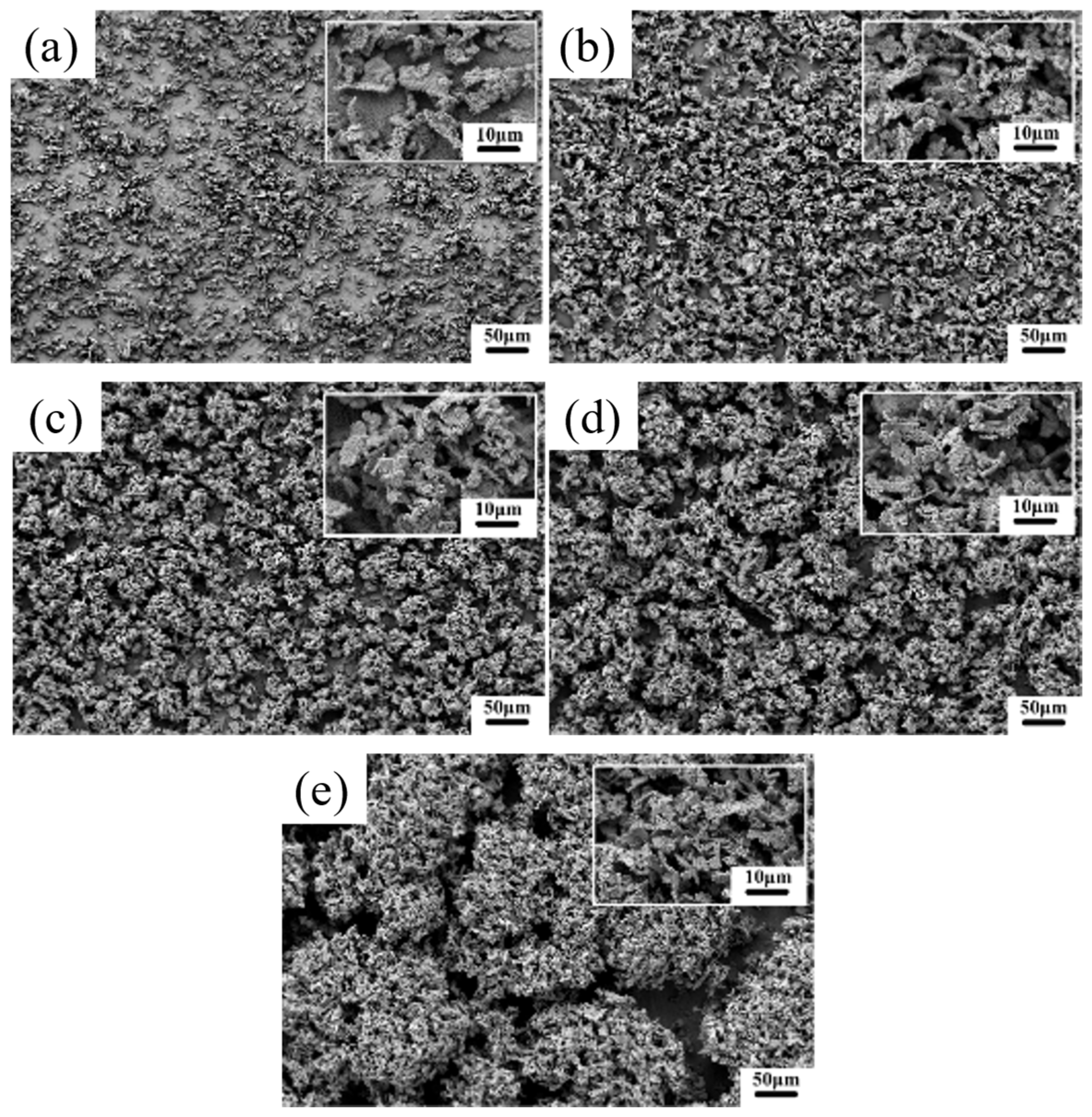
The SEM images of the surface morphology of the Ni–Gr coatings at different current densities are shown in Figure 2. At lower current densities (1 A/dm2), the particle distribution on the coating surface is relatively sparse, with locally visible dispersed agglomerates and distinct gaps between particles, resulting in a comparatively loose overall structure (Figure 2a). This is because at low current densities, the rate of nickel ion reduction and co-deposition with graphene nanoplatelets is relatively slow, resulting in a comparatively gentle nucleation and growth process. Consequently, the continuity and density of the coating are insufficient during its formation. As the current density increases (2–4 A/dm2), the density of the coating progressively increases, the particle number density increases, and the surface morphology becomes more uniform (Figure 2b–d). High-magnification micrographs show altered particle aggregation behaviour, with the aggregates becoming more compact. At this stage, the increased current density intensifies the cathode polarisation effect [38], promoting nickel ion reduction and the co-deposition efficiency of the graphene nanoplatelets. This results in more complete coating growth and a more continuous structure. When the current density increased to 5 A/dm2, large-scale agglomerates became distinctly visible on the coating surface. These agglomerates contained numerous fine particles and exhibited porous or dendritic characteristics (Figure 2e). This is because at high current densities, the reaction kinetics at the cathode surface change, leading to a substantial increase in the number of nucleation sites and accelerated growth rates. This promotes intense agglomeration growth between the nickel grains and graphene nanoplatelets, ultimately forming a coarse coating with a large agglomerated structure.
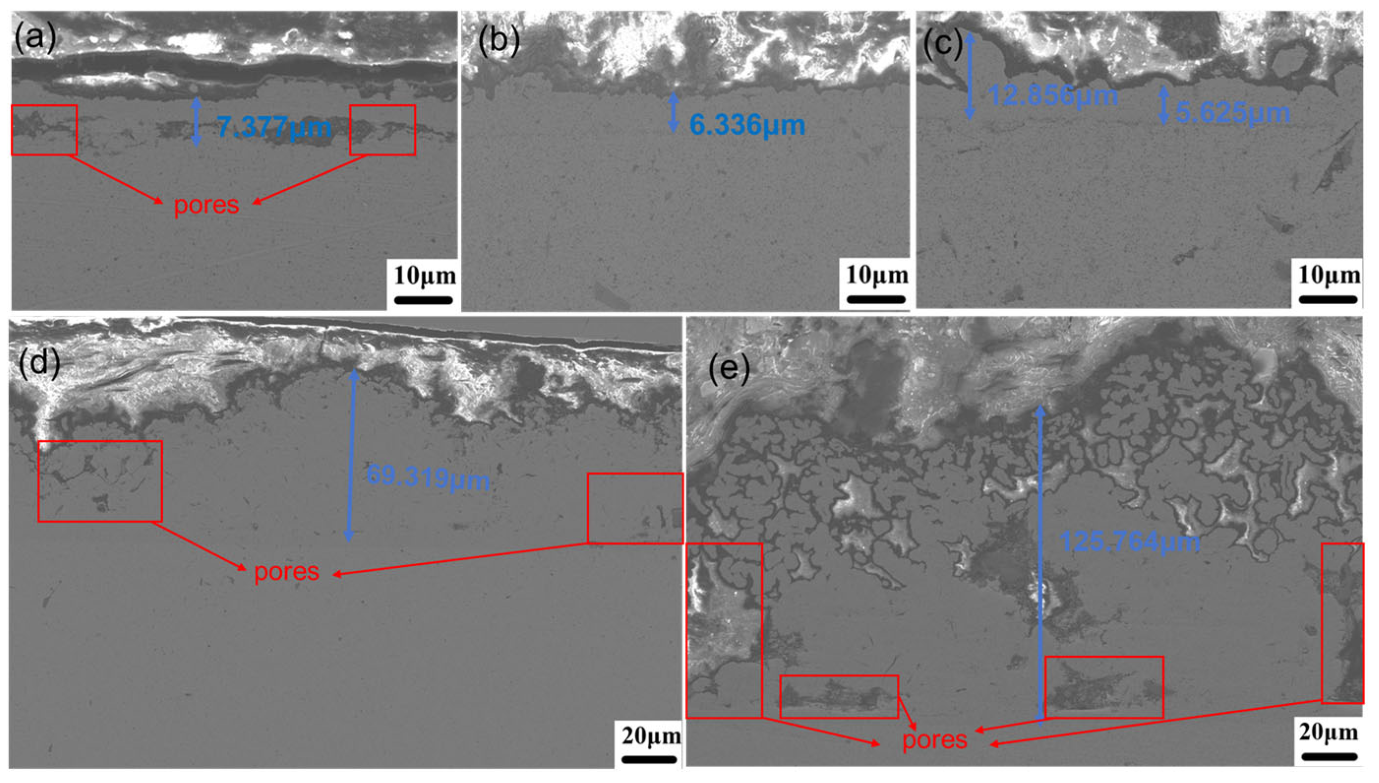
The SEM images of the cross-sectional of the Ni–Gr coatings at different current densities are shown in Figure 3, illustrating that current density exerts a significant regulatory effect on the coating thickness and compactness. Within the low current density range (1–3 A/dm2), the coating thickness remains relatively thin, arising from the restricted migration rate of Ni2+ ions and graphene nanoplatelets, which results in a slow electrodeposition rate. However, weaker cathodic polarisation in this range promotes relatively uniform nucleation and growth of grains, forming a structurally compact coating with fine grain size (e.g., the coating at 2 A/dm2 exhibits optimal compactness). Specifically, at 1 A/dm2, extremely weak cathode polarisation reduces nucleation efficiency, leading to grain coarsening and decreased packing density; although the macroscopic thickness increases due to loosely stacked grains, the actual effective deposition quantity does not improve significantly. Upon increasing the current density to 4–5 A/dm2, ion migration and deposition processes accelerate markedly, causing the coating thickness to surge to 69.319–125.764 μm. However, this is accompanied by significant structural defects (e.g., large-sized pores and interfacial inhomogeneities), which arises from strong cathode polarisation inducing an imbalance in grain growth kinetics, leading to excessive nucleation aggregation and defect accumulation, thus forming a “thick and porous” coating structure.

3.1.2. Microstructure

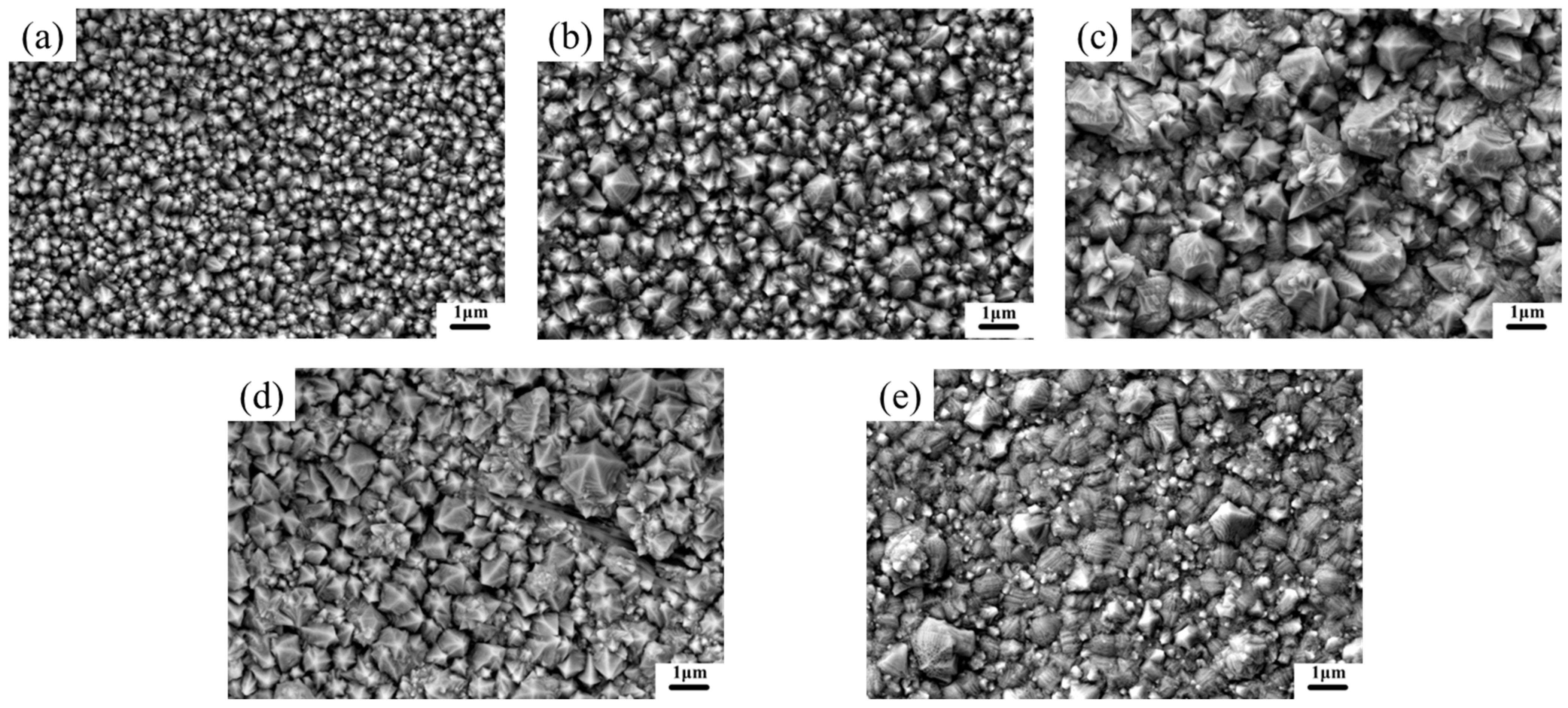
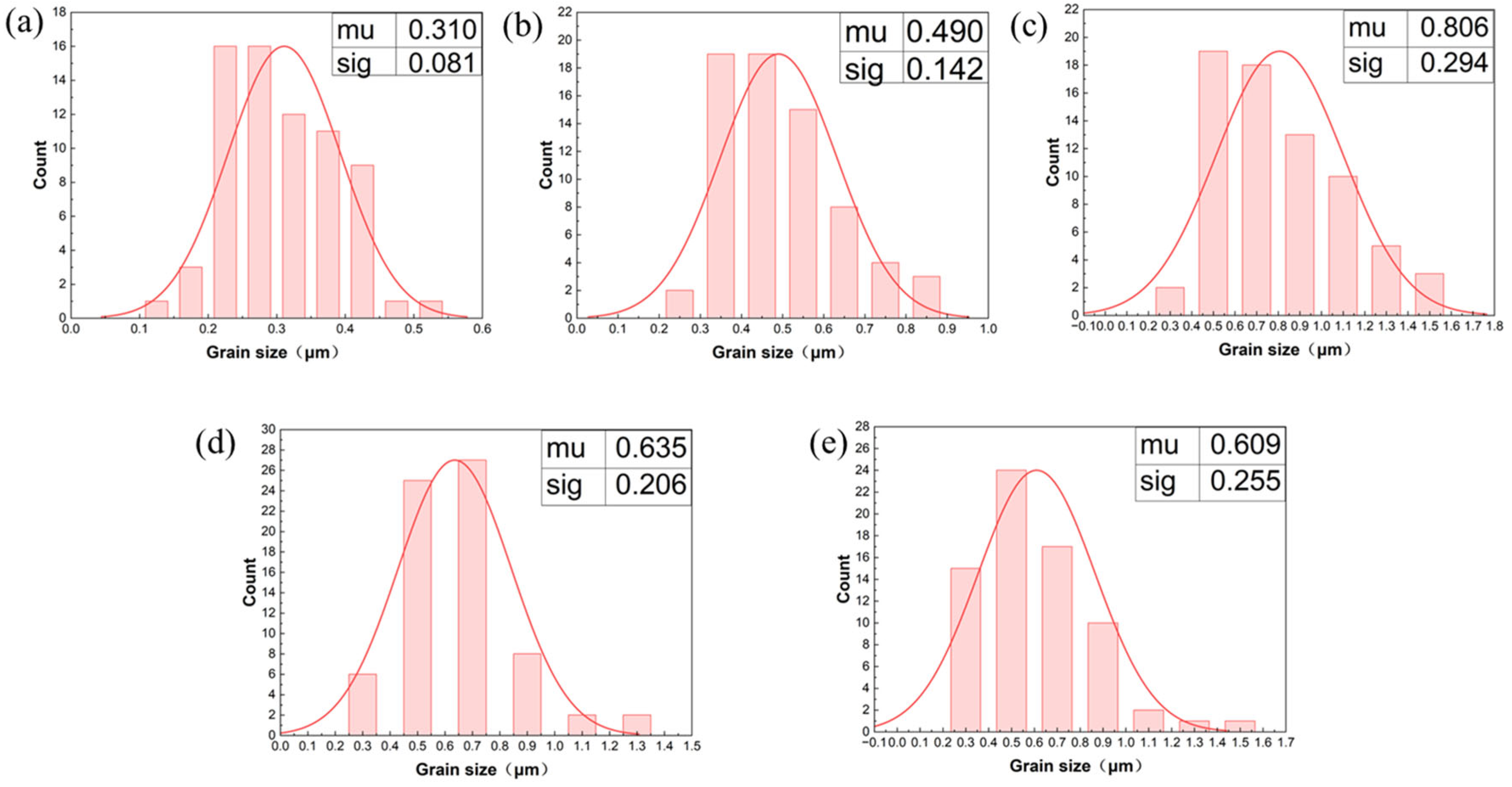
The SEM images of the nickel grains within the Ni–Gr coating at different current densities and the statistical distributions of the grain sizes are shown in Figure 4 and Figure 5, respectively. At low current densities (1 A/dm2), the nickel grains exhibit a nanoscale, near-isotropic morphology (Figure 4a), with sizes concentrated between 0.2 and 0.4 μm and a uniform distribution (Figure 5a). This arises from mild cathode polarisation at low current densities, which moderate the nickel ion reduction rate. Concurrently, graphene nanoplatelets provide abundant hetero-nucleation sites for nickel, where the nucleation rate significantly exceeds the grain growth rate, thereby facilitating a fine-grained, dense structure [39]. As the current density increases to the medium range (2–4 A/dm2), the grain size of the nickel progressively increases, resulting in the formation of polyhedral crystallographic morphologies such as prisms and pyramids (Figure 4b–d). The grain size distribution extends towards larger dimensions, whereas the uniformity decreases (Figure 5b–d). This phenomenon arises from the enhanced cathode polarisation and accelerated nickel ion reduction kinetics induced by increased current density. Concurrently, the co-deposition behaviour between the graphene nanoplatelets and nickel grains changes with the current density, altering the grain growth pattern. When the current density increases to 5 A/dm2, the nickel grains exhibit size heterogeneity and morphological irregularities, with large polyhedral grains coexisting alongside fine secondary grains and localised agglomerations (Figure 4e). The grain size distribution becomes extremely broad (Figure 5e), attributed to the sharp increase in the cathode overpotential at high current densities, which triggers a nucleation–growth rate imbalance, while reduced graphene nanoplatelet dispersion or localised aggregation interferes with uniform nickel ion reduction, ultimately leading to complex grain morphology and size distribution.

3.1.3. Phase Composition

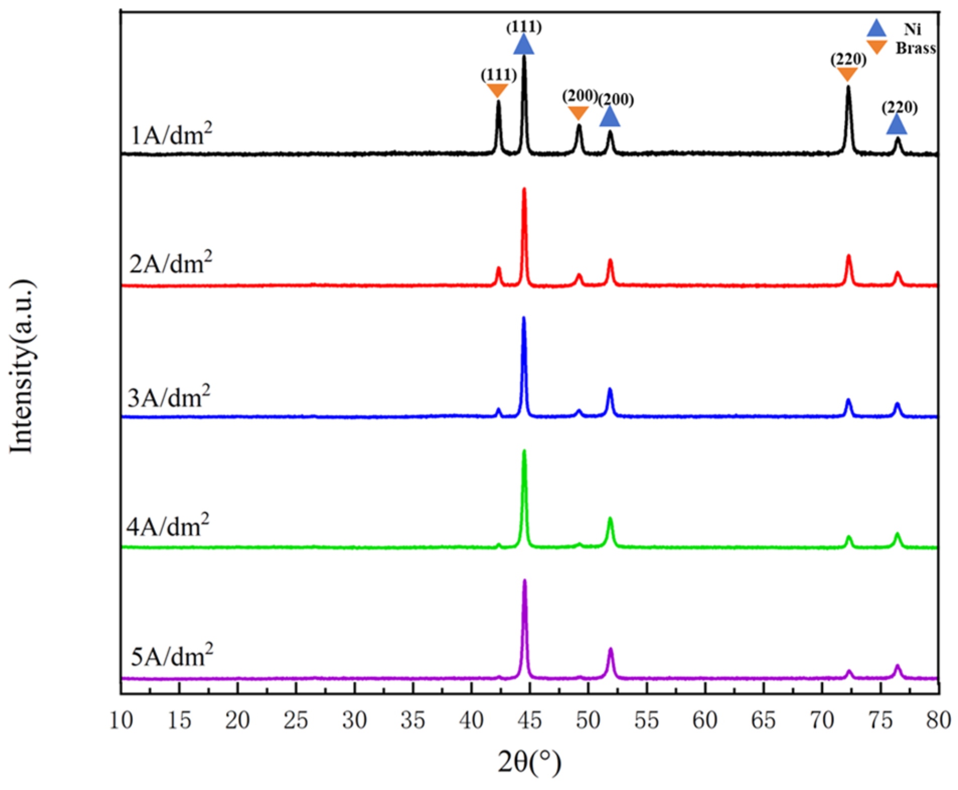
The XRD patterns of the Ni–Gr coatings deposited at different current densities on a brass substrate are shown in Figure 6. All the coatings exhibit characteristic diffraction peaks of face-centred cubic (fcc) nickel (Ni), such as the (111), (200), and (220) planes. The preferred orientation of the pure Ni coating is (200), whereas that of the Ni-Gr coating shifts to (111) because of the introduction of graphene nanoplatelets. This change arises from the alteration in growth kinetics caused by the interfacial interactions between the graphene nanoplatelets and nickel [40]. No characteristic diffraction peaks for the graphene nanoplatelets were detected, attributable to its low mass fraction within the coating, where its diffraction signal was masked by intense Ni diffraction peaks. Diffraction signals from the brass substrate were visible at low current densities. As the current density increased, the substrate diffraction peaks gradually weakened until they disappeared. This reflects a significant increase in the coating thickness at high current densities, effectively masking the substrate phase without the formation of new phases.
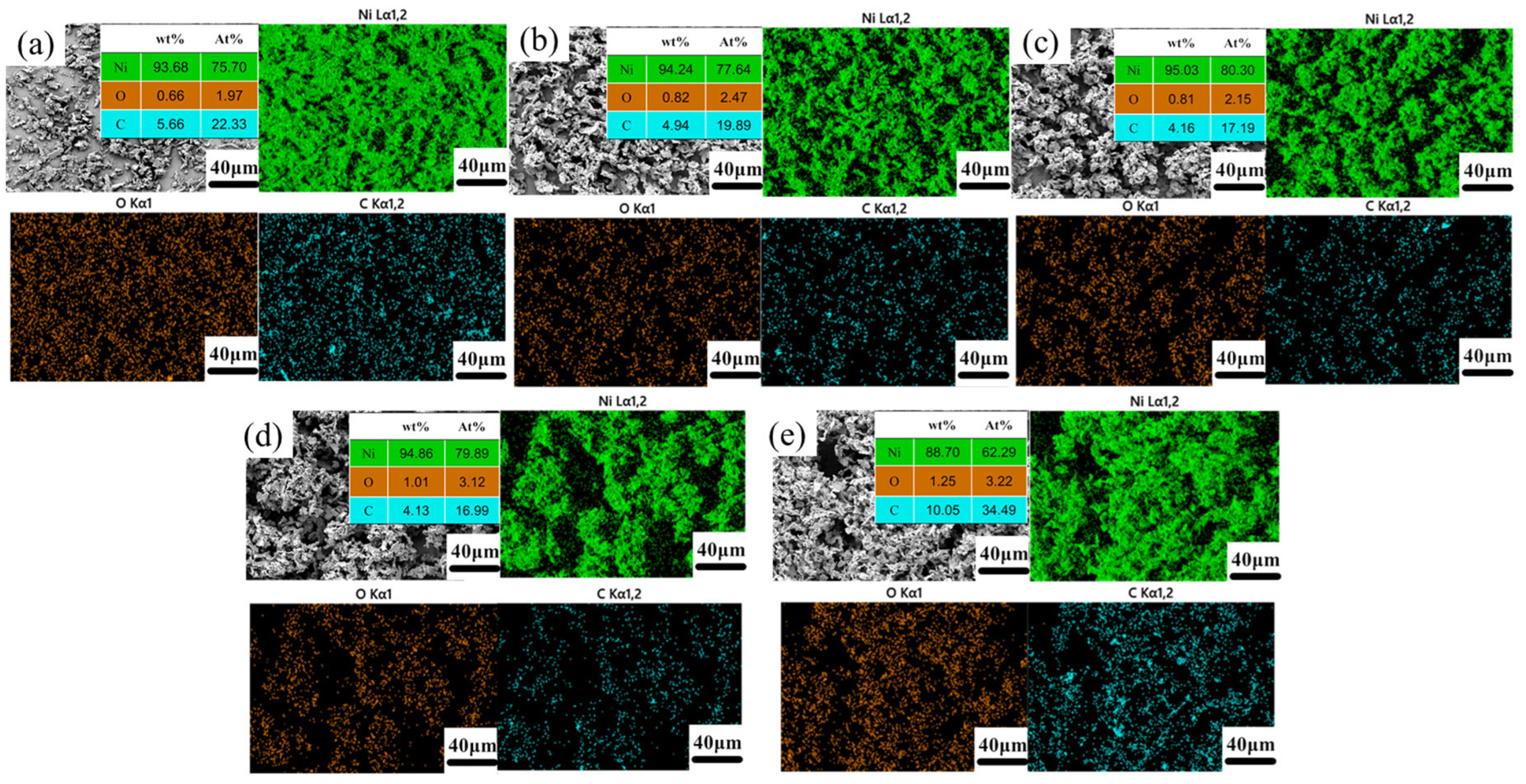
The EDS surface scanning and quantitative analysis of the Ni–Gr coatings prepared at different current densities are shown in Figure 7. Nickel (Ni) is distributed continuously and uniformly throughout the coating, demonstrating the integrity of nickel deposition; the uniformity of carbon (C), the characteristic element of graphene nanoplatelets, varies significantly with current density. At low current densities, the carbon distribution is more uniform (with a higher atomic fraction and improved dispersion), which is consistent with the uniform co-deposition behaviour of the graphene nanoplatelets at low currents and its hetero-nucleation promotion effect on nickel. As the current density increases, the uniformity of the C distribution decreases, with a heightened tendency towards localised aggregation. This reflects accelerated electrodeposition kinetics under high-current conditions, leading to reduced graphene nanoplatelet dispersion and altered co-deposition behaviour. The distribution of oxygen correlates with that of carbon, which arises from oxidation at the coating surface or the adsorption of corrosive media, thus indirectly reflecting the evolution of the state of the coating surface with increasing current density.
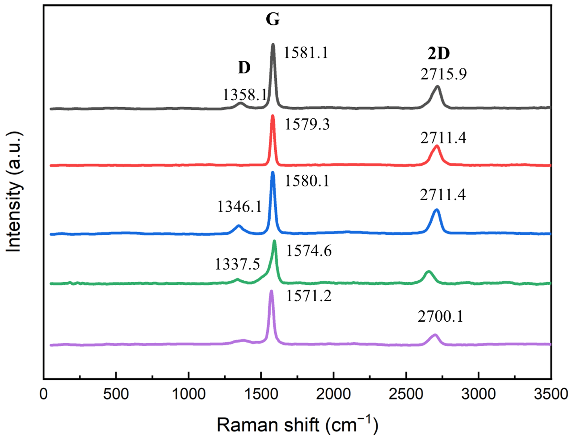
Raman spectroscopy can further confirm the presence of graphene. The Raman spectrum of the Ni–Gr coatings deposited at different current densities on a brass substrate are shown in Figure 8, the presence of graphene nanoplatelet in Ni–Gr composite coatings is confirmed by Raman spectroscopy through its characteristic D (~1350 cm−1), G (~1580 cm−1), and 2D (~2700 cm−1) peaks, with variations in their intensity, position, and profile across different current densities indicative of Gr’s structural integrity and dispersion within the nickel matrix.
In summary, Current density serves as a key regulator of the microstructure of Cu-based Ni–Gr composite coatings. At 2 A/dm2, moderate cathode polarization optimizes the balance between Ni nucleation and grain growth, yielding fine, dense grains with uniform graphene nanoplatelet dispersion and a face-centered cubic (fcc) fine-grained preferred orientation. Deviation from this optimal value induces structural degradation: low current density (1 A/dm2) leads to insufficient nucleation and relatively loose grain stacking, while high current densities (3–5 A/dm2) intensify polarization, causing Ni grain coarsening, graphene nanoplatelet agglomeration, and coating defects. These microstructure variations directly lay the structural foundation for the subsequent differences in coating comprehensive performance.

3.2. Effect of Current Density on Coating Properties

Current density directly governing their performance of Ni-Gr coatings [34,39,40]. This study investigates its effect on properties to clarify the process-property correlation, identify the optimal current density for multi-performance synergy, and provide technical guidance for Cu-based Ni–Gr coatings in electronic heat dissipation.

3.2.1. Microhardness

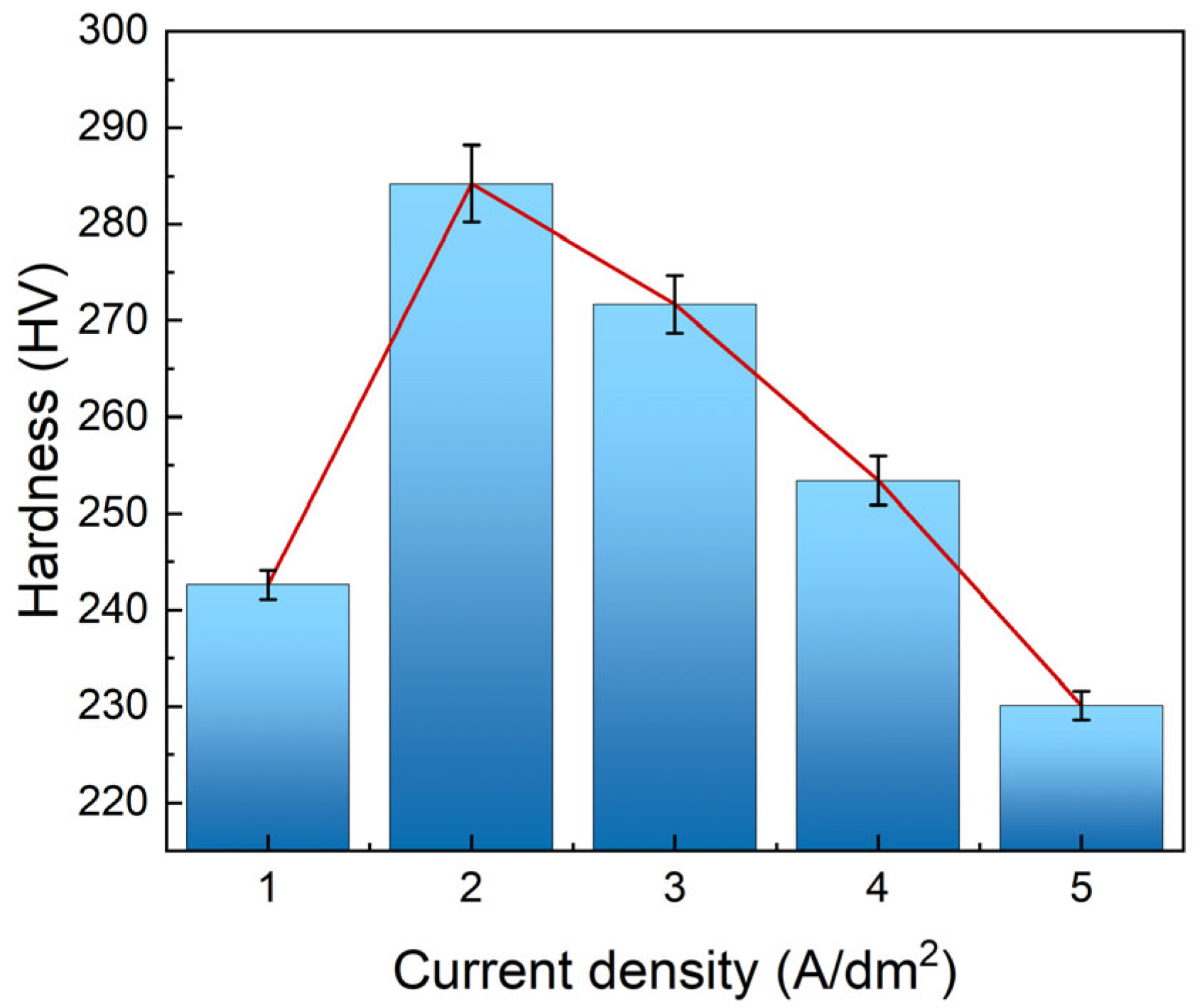
The Vickers hardness values of the Ni–Gr coatings at different current densities are shown in Figure 9. The Vickers hardness of the Ni–Gr coatings initially tends to increase but then decreases with increasing current density. At 1 A/dm2, mild cathode polarisation results in a gradual rate of nickel ion reduction and graphene nanoplatelet co-deposition, failing to fully stimulate the hetero-nucleation and dispersion strengthening effects of the graphene nanoplatelets, leading to inadequate coating density and uneven graphene nanoplatelet dispersion. Consequently, the hardness remains relatively low (242 HV). At 2 A/dm2, the cathode polarisation optimally aligns with the co-deposition kinetics. Moderately enhanced cathode polarisation significantly refines the nickel grains through hetero-nucleation effects while achieving optimal graphene nanoplatelet dispersion within the coating. Leveraging the synergistic effects of dispersion strengthening and fine-grain strengthening mechanisms, the coating attains peak comprehensive strengthening performance, achieving a maximum hardness of 284 HV, while Li et al. [35] reported that the hardness of pure nickel coatings is 180 HV, representing an approximate hardness increase of 57.8%.As the current density continues to increase, the excessively high cathode overpotential disrupts the kinetic equilibrium of nucleation–growth, triggering nickel grain coarsening. Concurrently, the graphene nanoplatelet dispersion deteriorates, significantly diminishing its contributions to heterogeneous nucleation and dispersion strengthening. The grain coarsening-dominated hardness decay effect becomes predominant, resulting in a continuous decline in the coating hardness with increasing current density [41].

3.2.2. Wear Resistance

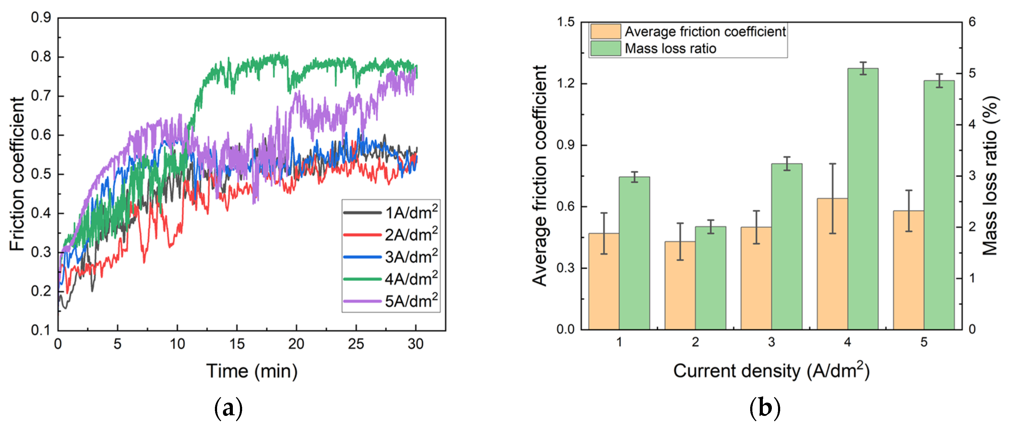
The friction coefficient curves, average friction coefficients, and mass loss rates of Ni–Gr coatings at different current densities are shown in Figure 10. At 1 A/dm2, nickel grains exhibit fine-grained characteristics but with suboptimal density, whereas graphene nanoplatelet dispersion requires optimisation. Fine-grain strengthening and graphene nanoplatelet dispersion strengthening effects are beginning to occur, resulting in a moderate average coefficient of friction and an intermediate mass loss rate. The optimal tribological performance occurs at 2 A/dm2. Under this current, the nickel grains are fine and dense, the graphene nanoplatelet dispersion is excellent, the concentrations of nickel and carbon are uniformly distributed, the hardness reaches its peak, and fine-grain strengthening synergizes optimally with the strengthening of the graphene nanoplatelet dispersion. This endows the coating with both ‘graphene nanoplatelet solid lubrication’ and ‘fine-grain dense structure resistance to plastic deformation’ capabilities, manifesting as the lowest average coefficient of friction (0.43) and minimal mass loss rate (2.01%), performance surpasses that of the nickel-graphene coating reported by Wan et al. [42] (optimal coefficient of friction: 0.61). As the current density increases to 3 A/dm2, the nickel grains coarsen and density decreases, leading to reduced uniformity in graphene nanoplatelet dispersion. The resulting decrease in hardness weakens the lubrication-load-bearing capacity of the graphene nanoplatelets, making the wear process prone to particle generation or interfacial delamination. Both the coefficient of friction and the mass loss rate subsequently increase. At 4–5 A/dm2, the nickel grains undergo significant coarsening and agglomeration, with an increasing amount of coating defects. Graphene nanoplatelets exhibit localised agglomeration/segregation, leading to further hardness reduction. Agglomerated graphene nanoplatelets not only lose their lubricating function but also become prone to forming weak points (where agglomerates readily delaminate to form abrasive particles), accelerating the wear process. Consequently, the average coefficient of friction and mass loss rate increase dramatically [43].

3.2.3. Corrosion Resistance

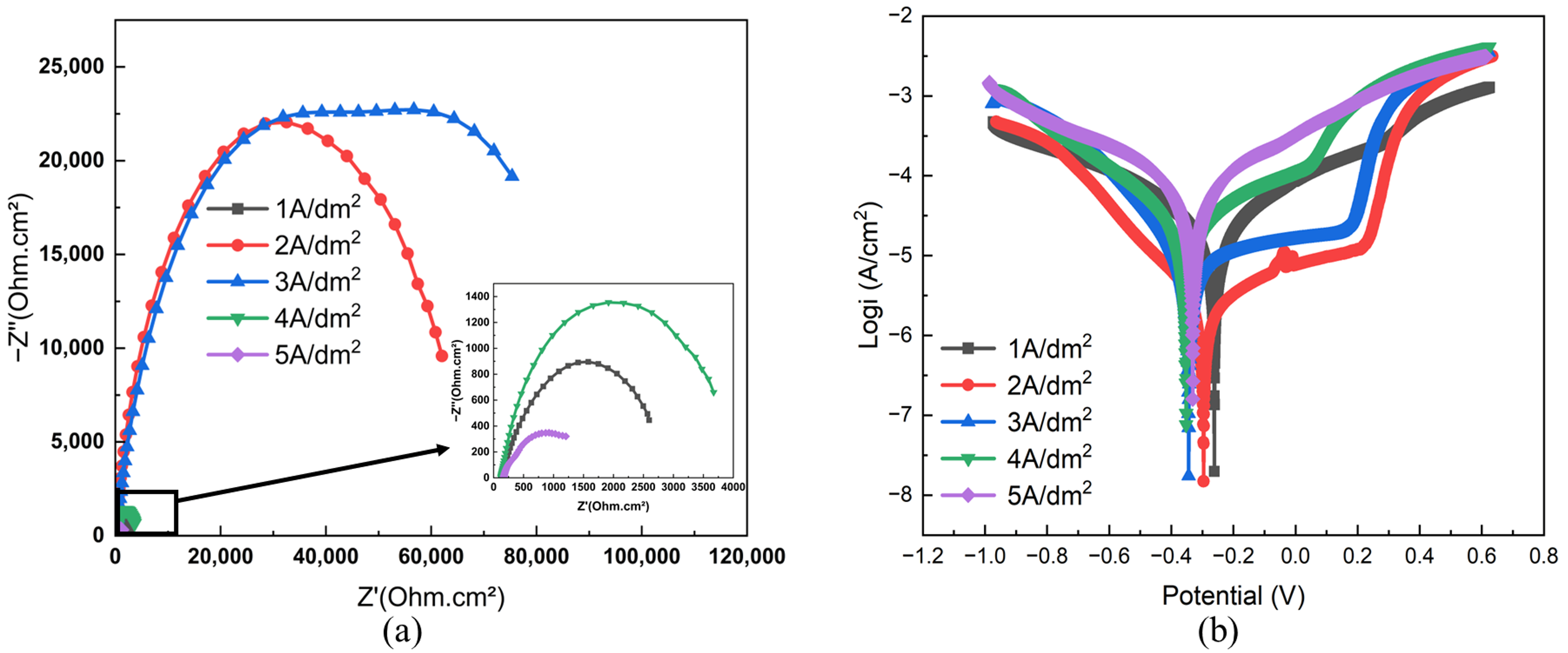
The electrochemical impedance spectroscopy (EIS) and Tafel curves of the Ni-Gr coatings at different current densities are shown in Figure 11. Table 3 presents the self-corrosion potential (Ecorr) and self-corrosion current density (Icorr) of the Ni–Gr coatings at various current densities. Combined with the microstructure of the coating, these findings reveal the corrosion resistance behaviour of the Ni–Gr coatings in a 3.5% NaCl solution at different current densities. At 1 A/dm2, the cathode polarisation is mild, with moderate rates of Ni2+ reduction and graphene nanoplatelet co-deposition. Although graphene nanoplatelets can refine nickel grains through ‘heterogeneous nucleation’, the coating density remains insufficient and the graphene nanoplatelet dispersion is not optimally uniform. Corrosive media (Cl) readily permeate through these ‘structural weak points’ to the substrate, accelerating charge transfer processes and reducing impedance. At 2 A/dm2, the EIS capacitive arc diameter reaches its maximum, whereas the corrosion current density (Icorr) is lowest at 1.8135 × 10⁻⁶ A/cm2. At this current, the cathodic polarisation and co-deposition kinetics exhibit optimal alignment. The nickel grains are fine and dense, with excellent graphene nanoplatelet dispersion. The increased effective specific surface area of the fine grains inhibits the penetration pathways for the corrosive medium, whereas the uniformly distributed graphene nanoplatelets form a ‘physical barrier’ that impedes Cl permeation. The synergistic effect of these two factors results in the strongest inhibition of charge transfer and the best corrosion resistance [44]. At 3 A/dm2, the EIS capacitive arc diameter is smaller than that at 2 A/dm2. The self-corrosion potential (Eccor) shifts negatively, the self-corrosion current density (Icorr) increases, and rising current enhances the cathodic overpotential. When the coarsening of the nickel grains commences, the uniformity of the graphene nanoplatelet dispersion decreases, and the synergistic effect of ‘fine-grain strengthening’ and the ‘graphene nanoplatelet barrier effect’ weakens. Corrosive media penetrate more readily, concurrently reducing the charge transfer resistance and corrosion resistance. When the current density increases to 4–5 A/dm2, the EIS capacitive arc diameter decreases markedly, whereas the self-corrosion current density (Icorr) increases further. Excessive cathode overpotential disrupts the nucleation–growth equilibrium (the growth rate becomes dominant), leading to widespread coarsening and agglomeration of nickel grains, a sharp increase in coating porosity and defect density, and a persistent deterioration in graphene nanoplatelet dispersion. The physical barrier effect of the graphene nanoplatelets progressively deteriorates from near-total failure to complete loss. Corrosive media (Cl) first rapidly permeate the coating and subsequently directly contact the substrate through penetrating defects. The charge transfer resistance progressively decreases, ultimately causing significant degradation in the corrosion resistance of the coating [45].

3.2.4. Thermal Conductivity

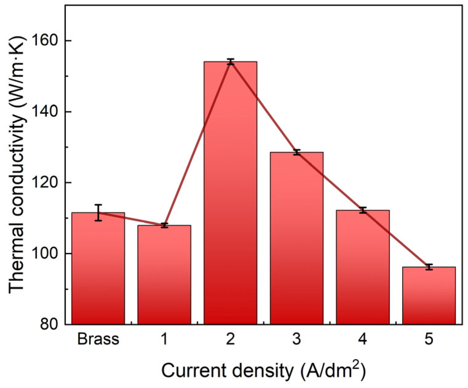
The variations in thermal conductivity (at 25 °C) for the brass substrate and Ni–Gr coatings at different current densities are shown in Figure 12. The thermal diffusivity (α), density (ρ), and specific heat capacity (Cp) for the Ni–Gr coatings on brass at different current densities are presented in Table 4. This evolution is closely related to the synergistic effect between the coating microstructure, graphene nanoplatelet dispersion, and thermal conductivity properties. Taking the thermal conductivity coefficient of brass as the reference benchmark, combined with Formula (1), it can be explained that at 1 A/dm2, the nickel grains exhibit fine crystalline characteristics but insufficient density. Inadequate coating density and uneven graphene nanoplatelet dispersion lead to enhanced phonon scattering at intergranular voids, discontinuous thermal conduction pathways, and increased interfacial thermal resistance. Although α approaches that of brass, Cp remains lower than that of brass, resulting in a relatively low thermal conductivity. At 2 A/dm2, the nickel grains are fine and dense with uniformly embedded graphene nanoplatelets and exhibit no significant voids or agglomerations. The fine-grained, dense structure eliminates pore-related thermal resistance sources. Uniformly dispersed graphene nanoplatelets construct efficient intergranular heat conduction pathways, maximising the phonon mean free path and minimising interfacial thermal resistance. α, ρ, and Cp synergistically reach peak values, increasing the thermal conductivity to its maximum (154 W/(m·K)). At 3 A/dm2, the nickel grains tend to coarsen, with a reduced density and localised aggregation of the graphene nanoplatelets. Although α increases slightly, intensified grain coarsening exacerbates inelastic phonon scattering at grain boundaries. The localised aggregation of graphene nanoplatelets disrupts thermal pathways, leading to a decrease in Cp and a consequent decline in thermal conductivity. At 4 A/dm2, the coarsening of the nickel grains and the graphene nanoplatelets significantly agglomerate, with the porosity and defect density of the coating increasing dramatically. The graphene nanoplatelets exist in the form of agglomerated clusters. Despite further increases in α, the aggregated graphene nanoplatelets and abundant pores form multiple thermal resistance barriers. Phonons undergo total reflection scattering at the pores, causing the graphene nanoplatelets to aggregate and lose their contribution to heat conduction. Cp decreases below the 1 A/dm2 level, and the thermal conductivity decreases to 70% of its peak value. At 5 A/dm2, severe grain coarsening occurs in the nickel accompanied by through-defects, extensive agglomeration or deintercalation of graphene nanoplatelets, and plating layer-weakened substrate–interface bonding, with through-defects causing thermal short-circuiting via air (air thermal conductivity at merely 0.026 W/(m·K)). Deintercalation and interfacial delamination of the graphene nanoplatelets further increase the interfacial thermal resistance, with both α and Cp reaching the test lower limits. The thermal conductivity decreases to the lowest value within the 1–5 A/dm2 range [34,46,47,48].
In summary, Current density significantly modulates the comprehensive performance of Cu-based Ni–Gr coatings. At the optimal 2 A/dm2, the coating achieves synergistic enhancement of multi-properties: peak Vickers hardness (284 HV), minimal friction coefficient (0.43) and wear rate (2.01%), lowest self-corrosion current density (1.8135 × 10⁻⁶ A/cm2), and maximum thermal conductivity (154 W/(m·K)). Deviation from this current density (1 A/dm2 or 3–5 A/dm2) leads to deteriorated performance, which is directly attributed to microstructural degradation (grain coarsening, graphene nanoplatelet agglomeration, or defect formation), confirming the “process–microstructure–property” correlation.

4. Conclusions

In this work, Ni-Gr coatings were fabricated on brass substrates via direct current electrodeposition, and the influence of current density (1–5 A/dm2) on their microstructure, mechanical, tribological, corrosion, and thermal properties was systematically investigated. The main findings are as follows:
(1)
Current density significantly regulates the microstructure of Ni–Gr coatings. At 2 A/dm2, nickel grains are fine and dense, and graphene nanoplatelet disperses uniformly in the nickel matrix, with the nickel phase exhibiting a face-centered cubic (fcc) structure with fine-grained preferred orientation. Deviation from this current density leads to nickel grain coarsening and graphene nanoplatelet dispersion deterioration.
(2)
The Ni–Gr coating at 2 A/dm2 achieves optimal comprehensive performance: a peak Vickers hardness of 284 HV, the lowest average friction coefficient (0.43) and wear mass loss rate (2.01%), a minimum self-corrosion current density of 1.8135 × 10⁻⁶ A/cm2 in 3.5 wt.% NaCl solution, and a maximum thermal conductivity of 154 W/(m·K) at room temperature, which is 40% higher than that of the brass substrate.
(3)
Graphene nanoplatelets are co-deposited with nickel atoms, and their dispersion state and the resultant microstructure (grain size, compactness) dominate the coating’s performance. The fine-grained and dense structure at 2 A/dm2 facilitates the formation of efficient heat conduction channels and physical barriers, while also enhancing mechanical strength and wear resistance.
(4)
The simultaneous improvement in thermal conductivity, wear resistance, and corrosion resistance makes these coatings promising for critical industrial applications, such as heat dissipation components in high-power electronic devices (e.g., 5G base station power amplifiers, server CPUs) and marine electronic equipment, where efficient heat dissipation, surface wear protection, and corrosion resistance are simultaneously required.

Author Contributions

Conceptualization, Z.Z. and H.W.; methodology, H.W., W.M. and Y.M.; validation, H.W., W.M. and Y.M.; formal analysis, H.W.; investigation, Z.Z. and H.W.; resources, Z.Z.; data curation, H.W., W.M. and Y.M.; writing—original draft preparation, H.W.; writing—review and editing, Z.Z.; visualization, H.W.; supervision, Z.Z.; project administration, Z.Z.; funding acquisition, Z.Z. All authors have read and agreed to the published version of the manuscript.

Funding

This study was financially supported by Special Project of Local Science and Technology Development Guided by the Central Government of China (24ZYQA035), Gansu Province Key R&D Plan Industrial Projects (24YFGC001), Scientific Research Project of Lanzhou Science and Technology Bureau (2023-1-23).

Institutional Review Board Statement

Not applicable.

Informed Consent Statement

Not applicable.

Data Availability Statement

Data are contained within the article.

Conflicts of Interest

The authors declare no conflicts of interest.

References

  1. Park, S.Y.; Yee, N.Y.; Baek, M.; Kim, H.S.; Lee, K.A. Microstructure heterogeneity, mechanical properties and thermal con-ductivity of pure copper fabricated by metal material extrusion additive manufacturing process. Mater. Sci. Eng. A 2025, 927, 147939. [Google Scholar] [CrossRef]
  2. Choong, Y.H.; Krishnan, M.; Gupta, M. Recent advances in the 3D printing of pure copper functional structures for thermal management devices. Technologies 2023, 11, 141. [Google Scholar] [CrossRef]
  3. Salmon, F.; Benisi Ghadim, H.; Godin, A.; Haillot, D.; Veillere, A.; Lacanette, D.; Duquesne, M. Optimizing performance for cooling electronic components using innovative heterogeneous materials. Appl. Energy 2024, 362, 122983. [Google Scholar] [CrossRef]
  4. Zhang, Y. Strengthening, Corrosion and Protection of High-Temperature Structural Materials. Coatings 2022, 12, 1136. [Google Scholar] [CrossRef]
  5. Fateh, A.; Aliofkhazraei, M.; Rezvanian, A. Review of corrosive environments for copper and its corrosion inhibitors. Arab. J. Chem. 2020, 13, 481–544. [Google Scholar] [CrossRef]
  6. Akhtar, S.S. A systematic design to develop high-performance sintered particulate copper-composite as heat spreader material. Eng. Sci. Technol. Int. J. 2022, 27, 101019. [Google Scholar] [CrossRef]
  7. Mizuuchi, K.; Inoue, K.; Agari, Y. Trend of the development of metal-based heat dissipative materials. Microelectron. Reliab. 2017, 79, 5–19. [Google Scholar] [CrossRef]
  8. Nguyen, D.H.; Ahn, H.S. A comprehensive review on micro/nanoscale surface modification techniques for heat transfer enhancement in heat exchanger. Int. J. Heat Mass Transfer 2021, 178, 121601. [Google Scholar] [CrossRef]
  9. Wang, T.; Xu, Y.; Liu, Z.; Li, G.; Guo, Y.; Lian, J.; Zhang, Z.; Ren, L. A chitosan/polylactic acid composite coating enhancing the corrosion resistance of the bio-degradable magnesium alloy. Prog. Org. Coat. 2023, 178, 107469. [Google Scholar] [CrossRef]
  10. Yu, H.; Guo, Q.; Wang, C.; Cao, G.; Liu, Y. Preparation and performance of PANI/CNTs composite coating on 316 stainless steel bipolar plates by pulsed electrodeposition. Prog. Org. Coat. 2023, 182, 107611. [Google Scholar] [CrossRef]
  11. Liao, F.Q.; Chen, Y.C. Siloxane-based epoxy coatings through cationic photopolymerization for corrosion protection. Prog. Org. Coat. 2022, 174, 107235. [Google Scholar] [CrossRef]
  12. Abdeen, D.; El Hachach, M.; Koc, M.; Atieh, M. A review on the corrosion behaviour of nanocoatings on metallic substrates. Materials 2019, 12, 210. [Google Scholar] [CrossRef]
  13. Nguyen-Tri, P.; Nguyen, T.A.; Carriere, P.; Ngo Xuan, C. Nanocomposite coatings: Preparation, characterization, properties, and applications. Int. J. Corros. 2018, 2018, 1–19. [Google Scholar] [CrossRef]
  14. Yasin, G.; Arif, M.; Mehtab, T.; Shakeel, M.; Khan, M.A.; Khan, W.Q. Metallic nanocomposite coatings. In Corrosion Protection at the Nanoscale, 1st ed.; Rajendran, S., Nguyen, T.A., Kakooei, S., Yeganeh, M., Li, Y., Eds.; Elsevier: Amsterdam, The Netherlands, 2020; pp. 245–274. [Google Scholar]
  15. Gong, B.L.; Ma, X.Q.; Wang, T.G.; Hou, J.L.; Ji, S.X.; Shen, X.X.; Min, Y.L.; Xu, Q.J.; Cao, H.J. Enhanced corrosion resistance of MXene/Zn-Al LDH coating on Al alloy under dry/humid and temperature alternating environments. Corros. Sci. 2025, 255, 113088. [Google Scholar] [CrossRef]
  16. Wang, J.F.; Zhang, M.; Dai, R.S.; Shao, L.; Tu, Z.B.; Zhu, D.D.; Xu, Z.Z.; Dai, S.; Zhu, L. Wear and electrochemical corrosion behaviors of Cu matrix WC-Co reinforced composite coating prepared by cold spray. Surf. Coat. Technol. 2024, 488, 131001. [Google Scholar] [CrossRef]
  17. Xu, L.; Wang, R.; Gen, M.; Lu, L.; Han, G. Preparation and properties of graphene/nickel composite coating based on textured surface of aluminum alloy. Materials 2019, 12, 3240. [Google Scholar] [CrossRef] [PubMed]
  18. Dhand, D.; Grewal, J.S.; Kumar, P. Study and comparison of wear behaviour of Ni-Al2O3 coatings deposited by hot and cold spray. Surf. Topogr. Metrol. Prop. 2021, 9, 045056. [Google Scholar] [CrossRef]
  19. Kainz, C.; Schalk, N.; Tkadletz, M.; Saringer, C.; Winkler, M.; Stark, A.; Schell, N.; Julin, J.; Czttl, C. Thermo-physical properties of coatings in the Ti(B,N) system grown by chemical vapor deposition. Surf. Coat. Technol. 2020, 384, 125318. [Google Scholar] [CrossRef]
  20. Stewart, J.A.; Dingreville, R. Microstructure morphology and concentration modulation of nanocomposite thin-films during simulated physical vapor deposition. Acta Mater. 2020, 188, 181–191. [Google Scholar] [CrossRef]
  21. Muench, F. Electroless plating of metal nanomaterials. ChemElectroChem 2021, 12, 2993–3012. [Google Scholar] [CrossRef]
  22. Zhao, Z.; Luo, G.; Cheng, M.; Song, L. Water-Repellent Coatings on Corrosion Resistance by Femtosecond Laser Processing. Coatings 2022, 12, 1736. [Google Scholar] [CrossRef]
  23. Zhang, F.; Yao, Z.; Moliar, O.; Tao, X.; Yang, C. Nanocrystalline Ni coating prepared by a novel electrodeposition. J. Alloys Compd. 2020, 830, 153785. [Google Scholar] [CrossRef]
  24. Xia, F.; Li, Q.; Ma, C.; Guo, X. Preparation and characterization of Ni–AlN nanocoatings deposited by magnetic field assisted electrodeposition technique. Ceram. Int. 2020, 46, 2500–2509. [Google Scholar] [CrossRef]
  25. Walsh, F.C.; Wang, S.; Zhou, N. The electrodeposition of composite coatings: Diversity, applications and challenges. Curr. Opin. Electrochem. 2020, 20, 8–19. [Google Scholar] [CrossRef]
  26. Leng, X.Y.; He, S.L.; Wang, W.Q.; Zhang, H.N.; Wang, L.Y.; Song, J.L. Magnetic field-assisted electrodeposition: Mechanisms, materials, and multifunctional applications. J. Sci.-Adv. Mater. Dev. 2025, 10, 100967. [Google Scholar] [CrossRef]
  27. Chen, Y.; Pang, H.Z.; Liao, J.B.; Shangguan, S.M.; Panov, K.; Huang, Y.Y.; Tian, Z.J.; Gao, W.; Zhao, J.F. Multiphysics simulation and experimental study on uniformity of jet electrodeposited bronze coating in deep small hole. Electrochim. Acta 2025, 536, 146555. [Google Scholar] [CrossRef]
  28. Zafarghandi, M.S.; Tavandashti, N.P. Electrodeposition of hierarchically structured superhydrophobic Ni-PTFE composite coating with remarkable corrosion resistance, chemical and mechanical stability. Sci. Iran. 2024, 31, 907–919. [Google Scholar] [CrossRef]
  29. Gao, M.Y.; Liu, L.L.; Huang, Z.X.; Jiang, C.; Wang, X.; Huang, F.; Li, X.X.; Zhang, X.H. Electrodeposition and properties of Ni–W–Ti2AlC composite coatings. Ceram. Int. 2024, 50, 18832–18842. [Google Scholar] [CrossRef]
  30. Makarava, I.; Esmaeili, M.; Kharytonau, D.S.; Pelcastre, L.; Ryl, J.; Bilesan, M.R.; Vuorinen, E.; Repo, E. Influence of CeO2 and TiO2 Particles on Physicochemical Properties of Composite Nickel Coatings Electrodeposited at Ambient Temperature. Materials 2022, 15, 5550. [Google Scholar] [CrossRef]
  31. Balandin, A.A.; Ghosh, S.; Bao, W.; Calizo, I.; Teweldebrhan, D.; Miao, F.; Lau, C.N. Superior thermal conductivity of single-layer graphene. Nano Lett. 2008, 8, 902–907. [Google Scholar] [CrossRef] [PubMed]
  32. Ghosh, S.; Calizo, I.; Teweldebrhan, D.; Pokatilov, E.P.; Nika, D.L.; Balandin, A.A.; Bao, W.; Miao, F.; Lau, C.N. Extremely high thermal conductivity of graphene: Prospects for thermal management applications in nanoelectronic circuits. Appl. Phys. Lett. 2008, 92, 151911. [Google Scholar] [CrossRef]
  33. Huang, Z. Study on Preparation and Properties of High Thermal Conductivity Composites Based on Graphene. Master’s Thesis, Anhui University, Hefei, China, 2019. [Google Scholar]
  34. Yang, L.L.; Zhu, Y.J.; Liu, H.K.; Guo, T.; Tang, H.; Ya, S.D.; Li, Y.; Wang, H.G.; Luo, Y.L.; Ma, J.M.; et al. Co-deposition and thermal conductivity of nickel–graphene composite coatings on copper surface. Appl. Phys. A 2023, 129, 757. [Google Scholar] [CrossRef]
  35. Li, X.S.; Shen, Q.Q.; Zhang, Y.; Wang, L.L.; Nie, C.Y. Wear behavior of electrodeposited nickel/graphene composite coating. Diam. Relat. Mater. 2021, 119, 108589. [Google Scholar] [CrossRef]
  36. Zhang, R.Y.; Yang, K.; Zhang, Y.P.; Tao, B.; Wang, S.Q.; Cheng, Q.L. Long-term anticorrosion performance of a modifier-free Ni–Graphene superhydrophobic coating. Mater. Today Commun. 2024, 41, 111053. [Google Scholar] [CrossRef]
  37. Cheng, D.; Zhang, L.; Zhu, Y.; Xia, H.; Li, N.; Song, W.; Bai, H.; Ma, H. Preparation and Properties of Electrodeposited Ni-B-Graphene Oxide Composite Coatings. Materials 2022, 15, 2287. [Google Scholar] [CrossRef]
  38. Zhang, W.W.; Li, B.S.; Mei, T.Y.; Li, M.Y.; Hong, M.; Yuan, Z.W.; Chu, H.Q. Effects of graphene oxide and current density on structure and corrosion properties of nanocrystalline nickel coating fabricated by electrodeposition. Colloids Surf. A Physicochem. Eng. Asp. 2022, 648, 129220. [Google Scholar] [CrossRef]
  39. Yasin, G.; Arif, M.; Shakeel, M.; Dun, Y.C.; Zuo, Y.; Khan, W.Q.; Tang, Y.M.; Khan, A.; Nadeem, M. Exploring the Nickel–Graphene Nanocomposite Coatings for Superior Corrosion Resistance: Manipulating the Effect of Deposition Current Density on its Morphology, Mechanical Properties, and Erosion-Corrosion Performance. Adv. Eng. Mater. 2018, 20, 1701166. [Google Scholar] [CrossRef]
  40. Wang, J.Q.; Lei, W.N.; Deng, Y.; Xue, Z.M.; Qian, H.F.; Liu, W.Q.; Li, X.P. Effect of current density on microstructure and corrosion resistance of Ni-graphene oxide composite coating electrodeposited under supercritical carbon dioxide. Surf. Coat. Technol. 2019, 358, 765–774. [Google Scholar] [CrossRef]
  41. Ma, C.Y.; He, H.X.; Zhang, H.B.; Xia, F.F.; Li, H.X. Impact of ultrasonic power density on the structure and performance of Ni-W-SiC composite nanocoatings. Surf. Coat. Technol. 2025, 496, 131641. [Google Scholar] [CrossRef]
  42. Wan, Y.; Chen, L.; Tang, W.C.; Li, J.L. Effect of graphene on tribological properties of Ni based composite coatings prepared by oxidation reduction method. J. Mater. Res. Technol. 2020, 9, 3796–3804. [Google Scholar] [CrossRef]
  43. Li, H.X.; Ma, C.Y.; Xia, F.F.; Xiao, Z.M. Ultrasonic disorder-induced deposition of TiO2 nanorod arrays and C60 coating on carbon cloth for high-performance supercapacitor electrodes. Ultrason. Sonochem. 2025, 117, 107347. [Google Scholar] [CrossRef]
  44. Zarei, A.; Jafari, Z.; Dehghanian, C.; Pishbin, F.S. Diopside/graphene-oxide nanocomposite coatings on AZ31 Mg alloy for biomedical applications: Surface characteristics, corrosion, and biocompatibility properties. Surf. Coat. Technol. 2024, 479, 130482. [Google Scholar] [CrossRef]
  45. Pingale, A.D.; Belgamwar, S.U.; Rathore, J.S. Synthesis and characterization of Cu–Ni/Gr nanocomposite coatings by electro-co-deposition method: Effect of current density. Bull. Mater. Sci. 2020, 43, 66. [Google Scholar] [CrossRef]
  46. Cao, K.; Yu, M.; Liang, C.M.; Chen, H. Study on thermal conductivity of cold sprayed Cu coating. Surf. Eng. 2020, 36, 1058–1066. [Google Scholar] [CrossRef]
  47. Kim, Y.; Kim, M.; Seong, H.G.; Jung, J.Y.; Baeck, S.H.; Shim, S.E. Roles of silica-coated layer on graphite for thermal conductivity, heat dissipation, thermal stability, and electrical resistivity of polymer composites. Polymer 2018, 148, 295–302. [Google Scholar] [CrossRef]
  48. You, Y.X.; Zhang, B.B.; Tao, S.L.; Liang, Z.H.; Tang, B.; Zhou, R.; Yuan, D. Effect of Surface Microstructure on the Heat Dissipation Performance of Heat Sinks Used in Electronic Devices. Micromachines 2021, 12, 265. [Google Scholar] [CrossRef]
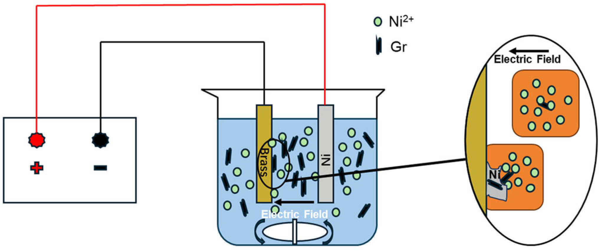
Figure 1. Schematic Diagram of the Electrodeposition Process.
Coatings 15 01360 g001
Figure 2. SEM images of Ni–Gr coatings deposited at different current densities: (a) 1 A/dm2, (b) 2 A/dm2, (c) 3 A/dm2, (d) 4 A/dm2, and (e) 5 A/dm2.
Coatings 15 01360 g002
Figure 3. Cross-sectional macroscopic morphology of Ni–Gr coatings at different current densities: (a) 1 A/dm2, (b) 2 A/dm2, (c) 3 A/dm2, (d) 4 A/dm2 and (e) 5 A/dm2.
Coatings 15 01360 g003
Figure 4. SEM of nickel grains in Ni–Gr coatings at different current densities: (a) 1 A/dm2, (b) 2 A/dm2, (c) 3 A/dm2, (d) 4 A/dm2, and (e) 5 A/dm2.
Coatings 15 01360 g004
Figure 5. Statistical distribution of the nickel grain sizes in the Ni–Gr coatings at different current densities: (a) 1 A/dm2, (b) 2 A/dm2, (c) 3 A/dm2, (d) 4 A/dm2, and (e) 5 A/dm2.
Coatings 15 01360 g005
Figure 6. XRD patterns of the Ni–Gr coatings prepared at different current densities.
Coatings 15 01360 g006
Figure 7. EDS on Ni–Gr coatings surfaces at different current densities: (a) 1 A/dm2, (b) 2 A/dm2, (c) 3 A/dm2, (d) 4 A/dm2, and (e) 5 A/dm2.
Coatings 15 01360 g007
Figure 8. Raman spectrum of Ni–Gr coatings prepared at different current densities.
Coatings 15 01360 g008
Figure 9. Microhardness of the Ni–Gr coatings at different current densities.
Coatings 15 01360 g009
Figure 10. Ni–Gr coatings at different current densities: (a) friction coefficient curve; (b) average friction coefficient and mass loss rate.
Coatings 15 01360 g010
Figure 11. Ni–Gr coatings at different current densities. (a) Electrochemical impedance spectroscopy (EIS) and (b) Tafel polarisation curve.
Coatings 15 01360 g011
Figure 12. Thermal conductivity of the Ni–Gr coatings on brass substrates at different current densities.
Coatings 15 01360 g012
Table 1. Composition of the plating solution.
CompositionConcentration (g/L)
NiSO4·6H2O240
NiCl2·6H2O45
H3BO340
C12H25SO4Na0.1
C7H5NO3S1
Graphene Nanoplatelets0.5
Table 2. Process parameters.
ParameterValue
Current density (J)1–5 A/dm2
Bath temperature (T)50 °C
pH3.5
Stirring rate v200 r/min
Plating time ttotal30 min
Table 3. Self-corrosion potential and self-corrosion current density of Ni–Gr coatings at different current densities.
Current Density (A/dm2)Ecorr (V)Icorr (A/cm2)
1−0.261439.9066 × 10−6
2−0.295821.8135 × 10−6
3−0.343955.6102 × 10−6
4−0.352481.1148 × 10−5
5−0.330972.6735 × 10−5
Table 4. Comparison of the thermal diffusivity, density and specific heat capacity of Ni–Gr coatings on brass substrates at different current densities.
α (mm2/s)ρ (g/cm3)Cp (J/(g·K))
1 A/dm234.1838.10.39
2 A/dm233.8088.10.562
3 A/dm235.2388.10.454
4 A/dm236.528.10.379
5 A/dm231.2468.10.38
Brass34.4168.10.4
Disclaimer/Publisher’s Note: The statements, opinions and data contained in all publications are solely those of the individual author(s) and contributor(s) and not of MDPI and/or the editor(s). MDPI and/or the editor(s) disclaim responsibility for any injury to people or property resulting from any ideas, methods, instructions or products referred to in the content.