Article

Comparison of Microstructure and Properties of CoCrMo Coatings Prepared by High-Speed and Conventional Laser Cladding

1
School of Mechanical and Energy Engineering, Shanghai Technical Institute of Electronics & Information, Shanghai 201411, China
2
Shenyang Dalu Laser Technology Co., Ltd., Shenyang 110136, China
3
Institute of Metal Research, Chinese Academy of Sciences, Shenyang 110136, China
*
Author to whom correspondence should be addressed.
Coatings 2025, 15(10), 1200; https://doi.org/10.3390/coatings15101200 (registering DOI)
Submission received: 20 July 2025 / Revised: 17 August 2025 / Accepted: 21 August 2025 / Published: 12 October 2025

Abstract

High-speed laser cladding technology is an innovative process that reduces costs and enhances coating quality. In this study, CoCrMo wear-resistant coatings were fabricated on a 40Cr steel substrate using high-speed laser cladding technology and compared to CoCrMo coatings produced by traditional methods. The effects of both processes on the microstructure, nanoindentation characteristics, and wear behavior of CoCrMo coatings were examined. The results show that the phase compositions of both coatings include γ-Co solid solution and ε-Co solid solution. The high cooling rate of high-speed laser cladding significantly suppressed Mo precipitation, enhancing Mo solid solution strengthening. Additionally, the fine-grain strengthening effect induced by the high cooling rate contributed significantly to the coatings’ mechanical properties. The nano-hardness of the HS-CoCrMo coatings reached approximately 5.18 ± 0.23 GPa, 1.2 times higher than that of the N-CoCrMo coatings. Furthermore, the generalized hardness, H/E ratio, and H3/E2 ratio of HS-CoCrMo coatings were improved. This increase in nano-hardness significantly boosted the wear resistance of HS-CoCrMo coatings, yielding an average friction coefficient of approximately 0.466, with wear volume and specific wear rate values of 6.55 × 106 μm3 and 0.87 × 10⁻⁵ mm3/N·m, respectively, outperforming the N-CoCrMo coatings. The main wear mechanisms for the HS-CoCrMo coatings were abrasive wear, adhesive wear, and oxidative wear. In conclusion, high-speed laser cladding technology produces high-performance, wear-resistant coatings with high productivity, offering broader application prospects for the metallurgical and power industries, while effectively reducing production cycles and usage costs.

1. Introduction

With the continuous advancement of industrial technology, the performance and quality of mechanical components are constantly improving. However, the failure rate caused by wear has been increasing year by year, becoming a key factor limiting the reliability and service life of equipment [1,2,3]. Wear-induced failures not only cause premature equipment breakdown but also lead to a significant waste of manpower, resources, and costs. As a result, the demand for enhancing the surface hardness and wear resistance of materials has become a major focus [4]. To meet this need, the development of surface coating and repair technologies has entered a new era, with laser additive manufacturing (LAM) demonstrating great potential in high-performance surface reinforcement. Currently, laser cladding (LC), as a mature surface modification process, can produce dense, defect-free coatings with excellent bonding strength and corrosion resistance, and is widely applied in metallurgy, aerospace, and automotive industries [5,6,7,8,9].
Laser cladding (LC), in particular, has shown promise for repairing or producing surface-modified coatings with excellent wear and corrosion resistance [10]. However, traditional laser cladding processes face limitations such as low productivity (about 10–50 cm2/min), limited coverage, and difficulty avoiding cracks and defects, which restricts widespread industrial application [11]. Additionally, laser cladding offers a wide choice of cladding materials, controllable coating thickness, and minimal heat input, making it well-suited for industrial applications. However, the productivity of traditional laser cladding remains low (about 10–50 cm2/min), which is inadequate for the large-scale cladding requirements of industrial components [12]. Furthermore, issues such as tempering and softening in overlap zones result in structural and property inconsistencies between overlap and non-overlap areas, limiting the development and application of laser cladding.
To address these challenges, RWTH Aachen University and the Fraunhofer Institute for Laser Technology (ILT) have developed extreme high-speed laser cladding (EHLA) [13]. This innovative technology boosts cladding line speed from 1.2 m/min to 200 m/min, enabling the preparation of cladding layers approximately 5 µm thick over areas of around 500 cm2/min, significantly enhancing the productivity of laser cladding [14,15].
To balance cladding layer thickness and production efficiency, high-speed laser cladding technology can be employed. Typically, the cladding speed of high-speed laser cladding lies between that of conventional and ultra-high-speed laser cladding [16]. This method ensures production efficiency while maintaining a certain coating thickness. Additionally, high-speed laser cladding reduces large thermal stresses between the substrate and the cladding layer, improving cladding layer formability and reducing susceptibility to cracks [17]. Similarly, Du et al. [18] successfully deposited CoCrFeNiMn high-entropy alloy (HEA) on 316 stainless steel using ultra-high-speed laser cladding, achieving a stable face center cubic (FCC) structure, a hardness of 251 HV, and excellent wear resistance. The results indicate that ultra-high-speed laser deposition not only refines the microstructure but also markedly improves properties such as strength, wear resistance, and thermal fatigue. Consequently, the strengthening mechanisms and very low dilution rates offered by high-speed/ultra-high-speed laser cladding cannot be matched by conventional laser cladding [19,20].
Cobalt-based alloys have garnered significant interest in metallurgy, power generation, and aerospace industries due to their excellent wear and corrosion resistance. For example, Cui et al. [21] prepared cobalt-based coatings on 42CrMo steel using laser cladding and investigated the effects of process parameters on coating geometry, microstructure, and corrosion resistance. When the laser energy density reached 90 J/mm2, the coating exhibited minimal corrosion products and high corrosion resistance. Similarly, Smoqi et al. [22] applied laser energy deposition to fabricate multilayer Stellite 21 coatings on an Inconel 718 substrate, minimizing coating cracks by adjusting energy density and preheating. The results showed that, while cracks were present at an energy density of 200 J/mm2, thermal cracks in the inter-dendritic regions were reduced by preheating and optimized energy density due to elemental shifts and hard brittle phase formation.
Therefore, this study focuses on fabricating high-Mo content CoCrMo coatings via high-speed laser cladding, systematically comparing microstructures, crystallography, nano-hardness, and wear performance with those produced by conventional laser cladding. The aim is to reveal the advantages of high-speed laser deposition in improving coating microstructure and performance, providing a technical pathway for high-efficiency, environmentally friendly wear-resistant coating production and expanding its application in metallurgy, energy, aerospace, and other fields.

2. Experimental Materials and Methods

2.1. Materials and Preparation

In this study, 40Cr steel with dimensions of φ70 mm × 800 mm (Shenyang Shanda Steel Sales Co., Ltd., Shenyang, China) was selected as the substrate material for high-speed laser cladding. Prior to the cladding process, the substrate surface was ground and polished to ensure smoothness, and residual impurities were removed by cleaning with alcohol. The cladding material used for both high-speed and conventional laser cladding was CoCrMo alloy powder (Chengdu Kexinglong Metal Materials Co., Ltd., Chengdu, China),with a particle size ranging from 53 to 105 µm. The powder was dried before high-speed laser cladding to eliminate any moisture content. The chemical compositions of the 40Cr steel substrate and the CoCrMo alloy powder are provided in Table 1.
A schematic diagram of the high-speed laser cladding process is shown in Figure 1. Conventional laser cladding and high-speed laser cladding are performed using a TruDiode 3006 fiber laser (TRUMPF, Ditzingen, Germany), which has a maximum power of 3000 W and operates at a wavelength of 1080 nm. These processes are conducted on custom-designed processing machines. The process parameters for both laser cladding methods are detailed in Table 2, and all parameters have been optimized to ensure optimal process conditions. The selected laser cladding process parameters are listed in Table 2. To simplify the presentation, the CoCrMo coatings produced by high-speed laser cladding are referred to as HS-CoCrMo coatings, while the CoCrMo coatings fabricated using conventional laser cladding are referred to as N-CoCrMo coatings.

2.2. Metallographic Preparation and Characterization

Metallographic specimens of the HS-CoCrMo and N-CoCrMo coatings were cut using EDM cutting equipment (Shanghai Donghe Mechanical and Electrical Technology Co., Ltd., Shanghai, China), following methods similar to those outlined in previous literature [23]. The specimens were then corroded using a solution consisting of 20 g of Cu2SO4, 20 mL of HCl, and 100 mL of H2O for 10 s to reveal the microstructures. The microstructures and morphologies of the HS-CoCrMo and N-CoCrMo coatings were observed using an optical microscope (OM, ZEISS, Oberkochen, Germany) and a scanning electron microscope (SEM, ZEISS, Oberkochen, Germany). The elemental distributions within the coatings were analyzed using an energy-dispersive spectrometer (EDS, Oxford Instruments, High Wycombe, UK).
The phase compositions of the HS-CoCrMo and N-CoCrMo coatings were analyzed by X-ray diffraction (XRD, BRUKER, Billerica, MA, USA), with a scanning range of 30° to 100° and a scanning speed of 4°/min. To prepare the coatings for further analysis, they were electrolytically polished and etched using a 10% HClO4-90% alcohol solution at 20 V and 40 mA. After polishing, electron backscatter diffraction (EBSD, EDS, Oxford Instruments, High Wycombe, UK) was employed to examine the crystallographic features of the two coatings, with a scanning step size of 0.5 µm.

2.3. Nano-Indentation and Wear Behavior Testing

The cross-sectional microhardness of both coatings was measured using a microhardness tester (BRUKER, Billerica, MA, USA). The testing parameters were as follows: a load of 100 g, with the load held for 10 s, and the test was conducted from the top to the bottom of the coating. Three measurements were taken from different locations on the cross-section, and the average value was reported.
Nano-hardness and modulus of elasticity of the HS-CoCrMo and N-CoCrMo coatings were tested using a nanoindenter (BRUKER, Billerica, MA, USA). A triangular indenter was employed for the nanoindentation tests. The parameters for the tests were as follows: the indenter’s displacement speed was 10 nm/s, Poisson’s ratio was set to 0.3, and the maximum load applied was 15 mN. Nine tests were conducted on each coating surface, and the average value was calculated to ensure test accuracy. For the reciprocating friction and wear test, GCr15 steel balls with a diameter of 5 mm (BRUKER, Billerica, MA, USA) were used as the friction partners. The selected parameters for the test were as follows: a load of 15 N, a reciprocating speed of 14 mm/s, a reciprocating distance of 6 mm, and a wear duration of 60 min. These parameters were based on those used in previous studies [24]. After the wear test, the wear surfaces were characterized using a white light interference profilometer(BRUKER, Billerica, MA, USA), and the specific wear rate was calculated. The wear mechanisms were analyzed using SEM imaging (SEM, ZEISS, Oberkochen, Germany) of the wear surfaces. Prior to the nano-indentation, hardness, and friction wear tests, the surfaces of the test specimens were carefully sanded and polished to remove any visible scratches, ensuring accurate and reliable results.

3. Results and Discussion

3.1. Phase Composite

Figure 2 presents the XRD diffractograms of the HS-CoCrMo and N-CoCrMo coatings. Both coatings consist of a γ-Co solid solution and an ε-Co solid solution. In XRD patterns of similar coatings, the number of crystal planes corresponding to the diffraction peaks is directly related to the peak intensity. As a result, the HS-CoCrMo coating shows a significant increase in the number of (111), (220), and (311) crystalline facets. The high-speed laser cladding (HSLC) process further enhances the crystalline facet orientation of the HS-CoCrMo coating. Additionally, the intensity of the diffraction peaks is indicative of the degree of crystallization; the diffraction peaks at 44° and 92° for the HS-CoCrMo coating are notably stronger than those of the N-CoCrMo coating, suggesting that the γ-Co solid solution in the HS-CoCrMo coating possesses a higher crystallinity [25].
Figure 2b shows the diffraction peaks for both coatings in the 42–45° range. The diffraction angles for the γ-Co solid solution in the HS-CoCrMo and N-CoCrMo coatings are 43.52° and 43.66°, respectively, compared to the standard diffraction angle of γ-Co solid solution at 44.22° (PDF#15-0806). This demonstrates that the γ-Co diffraction peaks in both coatings shift to lower angles. According to Bragg’s law of diffraction, the lattice constant for the FCC phase can be expressed as follows [26]:
d = a h 2 + k 2 + l 2
d h k l = λ 2   sin   θ
where d represents the crystallographic spacing of the γ-Co solid solution; h, k, and l are the crystallographic indices; a is the lattice parameter; λ is the wavelength (λ = 1.5406 Å); and θ is the diffraction angle. The calculated results show that the crystal plane spacings of the γ-Co solid solutions in the two coatings are 2.0513 Å and 2.0494 Å, respectively. Compared to the standard γ-Co solid solution crystal plane spacing of 2.0467 Å, both coatings display increased lattice parameters, indicating more intense lattice distortion. This increased distortion is attributed to the significantly larger atomic radius of Mo relative to Co and Cr, which introduces greater strain when Mo atoms are incorporated into the γ-Co structure, resulting in a shift in the γ-Co diffraction peaks to lower angles. Furthermore, the HS-CoCrMo coating exhibits a more pronounced low-angle shift in diffraction peaks due to the higher cooling rate associated with high-speed laser cladding, which intensifies lattice distortion in the γ-Co phase [27]. The elevated cooling rate also enhances the solubility limit of Mo in the γ-Co solid solution, contributing to a further low-angle shift in the γ-Co diffraction peaks of the HS-CoCrMo coating produced by high-speed laser cladding.

3.2. Microstructure and Crystal Structure

To analyze the relationship between the two laser cladding methods and the formability of the coatings, single-track cladding experiments were performed on the substrate surface using both techniques. Figure 3a,b displays the macroscopic morphology of the N-CoCrMo and HS-CoCrMo coatings obtained through single-track cladding. The measured cross-sectional heights of the N-CoCrMo and HS-CoCrMo coatings are 1380 µm and 678 µm, respectively. It is evident that both coatings, prepared using the two laser cladding methods, form a strong metallurgical bond with the substrate. No porosity, cracks, or other defects were observed in the single-track cross-sections, indicating that the process parameters are well-suited for the cladding powder.
Figure 3c,d shows the macroscopic morphology of the N-CoCrMo and HS-CoCrMo coatings. The cross-sectional thicknesses of the two coatings are 1420 µm and 940 µm, respectively, with the N-CoCrMo coating being approximately 1.5 times thicker than the HS-CoCrMo coating. This is attributed to the higher laser energy density of the normal laser cladding process, which penetrates deeper into the substrate and causes more substrate cladding, thus increasing the dilution rate of the coating. Additionally, the N-CoCrMo coating exhibits a semicircular arc at the bonding zone, while the HS-CoCrMo coating shows a relatively smooth bonding zone, further supporting the observation that the HS-CoCrMo coating has a lower dilution rate.
Furthermore, the Marangoni effect was observed in the N-CoCrMo coatings, but not in the HS-CoCrMo coatings. The Marangoni effect can typically be calculated using the following equation [28]:
M a = γ L ρ μ 2
where Ma is the Marangoni coefficient, Δγ is the melt tension gradient, L is the melt pool width, ρ is the density of the melt in the melt pool, and μ is the melt viscosity in the melt pool. Compared to high-speed laser cladding, normal laser cladding features a higher energy density, which accelerates the powder melting rate and enhances the fluidity of the melt within the melt pool, leading to a decrease in melt viscosity. Furthermore, the increased energy density widens the melt pool and intensifies the temperature gradient within the pool, resulting in an elevated Marangoni coefficient (Ma). This, in turn, induces a noticeable Marangoni effect in the N-CoCrMo coatings. In contrast, the HS-CoCrMo coating, with its lower laser energy density, exhibits higher melt viscosity and a smaller melt tension gradient, which prevents the formation of a distinct Marangoni effect in the coating.
The metallographic microscopic morphology of the N-CoCrMo and HS-CoCrMo coatings is shown in Figure 4, with views of the top of the cross-section (Figure 4a,d), the middle of the cross-section (Figure 4b,e), and the coating–substrate bonding area (Figure 4c,f). No defects such as unmelted powder, porosity, cracks, or inclusions were observed in either coating. In the bonding area between the substrate and coating, a thin layer of planar crystals formed in both coatings. Columnar crystals then developed above the planar crystals, aligning in the direction of the temperature gradient and exhibiting clear epitaxial growth. In the middle section of both the N-CoCrMo and HS-CoCrMo coatings, columnar crystals predominate, growing in alignment with the temperature gradient. At the top of the coatings, however, both columnar and equiaxed crystals are present, displaying varying growth directions. This dendritic growth pattern can be explained by non-equilibrium solidification theory [29]. Figure 4g illustrates the relationship between crystal structure, crystal growth rate (R), and temperature gradient (G) under non-equilibrium solidification. The product of G and R determines the size of the microstructure within the melt pool, while the ratio of G to R governs crystal morphology. When G/R is high, planar crystals dominate; as G/R decreases, the structure transitions to cellular crystals, dendritic crystals, and finally equiaxed crystals as G/R becomes low [30]. Additionally, due to the higher cooling rate associated with high-speed laser cladding, the microstructure of HS-CoCrMo coatings is significantly finer than that of N-CoCrMo coatings.
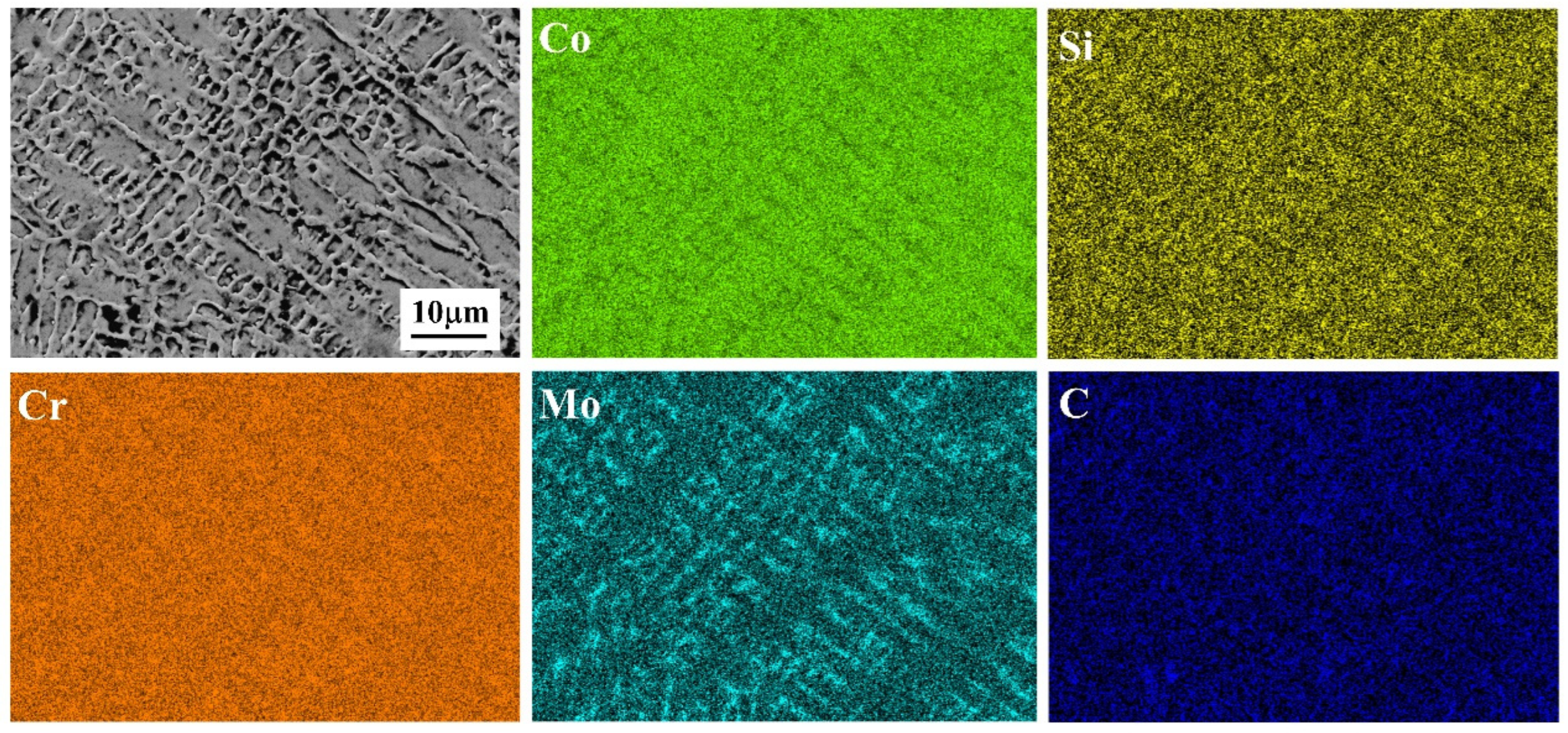
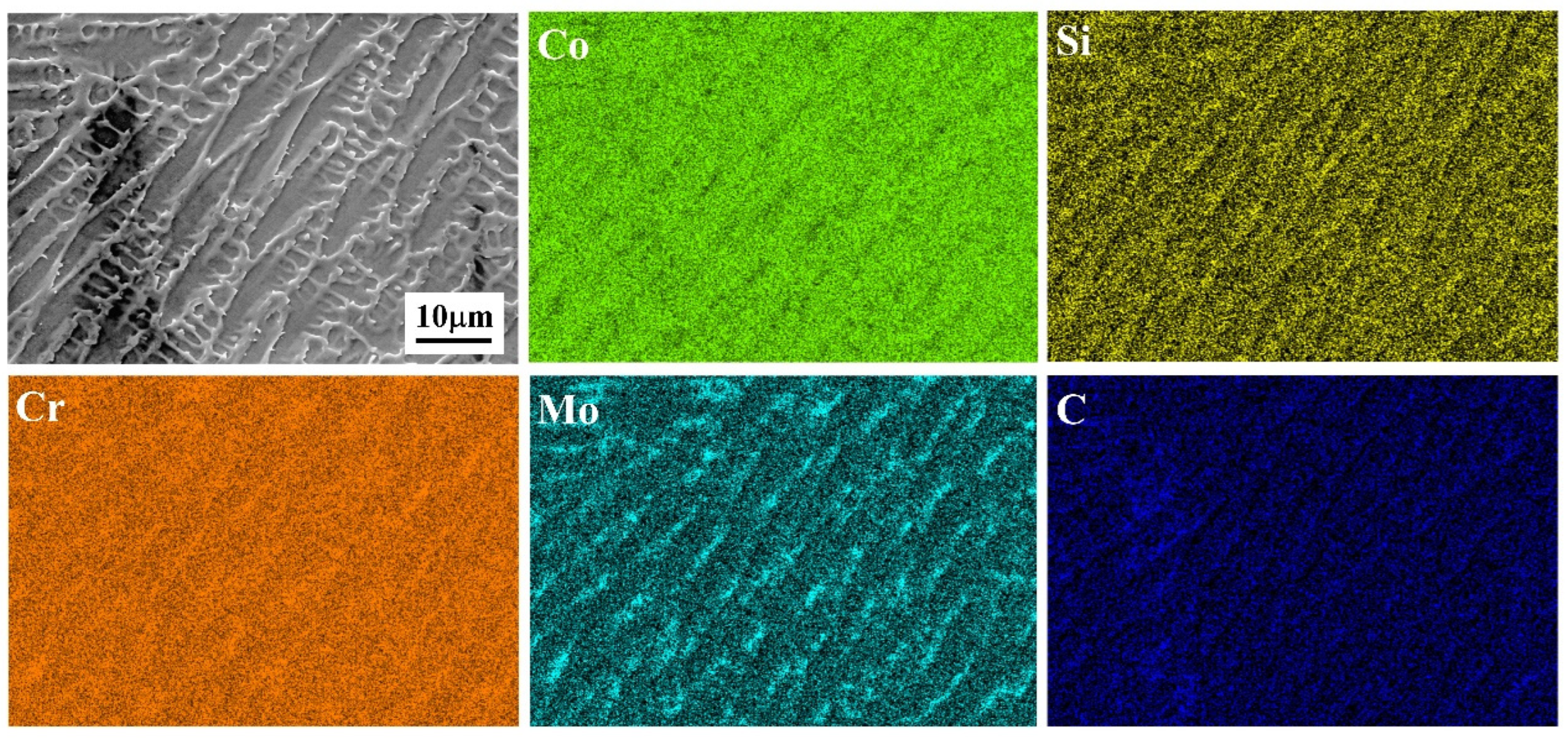
Figure 5 and Figure 6 illustrate the high-magnification microstructure and elemental distribution in the N-CoCrMo and HS-CoCrMo coatings. The elemental distribution in both coatings is generally similar: Co is predominantly enriched within dendrites, while Cr and Mo are concentrated in the inter-dendritic regions. Combined with the XRD diffraction results and thermodynamic calculations, this suggests that the dendrites consist of the γ-Co solid solution, while the inter-dendritic areas contain ε-Co solid solution. The tendency of Mo to accumulate in the inter-dendritic regions can be attributed to the solute segregation properties of Mo, as it has a partition coefficient of less than 1 in the FCC phase, causing it to segregate during solidification. A small amount of Mo is also present within the dendrites, indicating partial solid solution strengthening of the γ-Co solid solution by Mo, which enhances its strength [31].
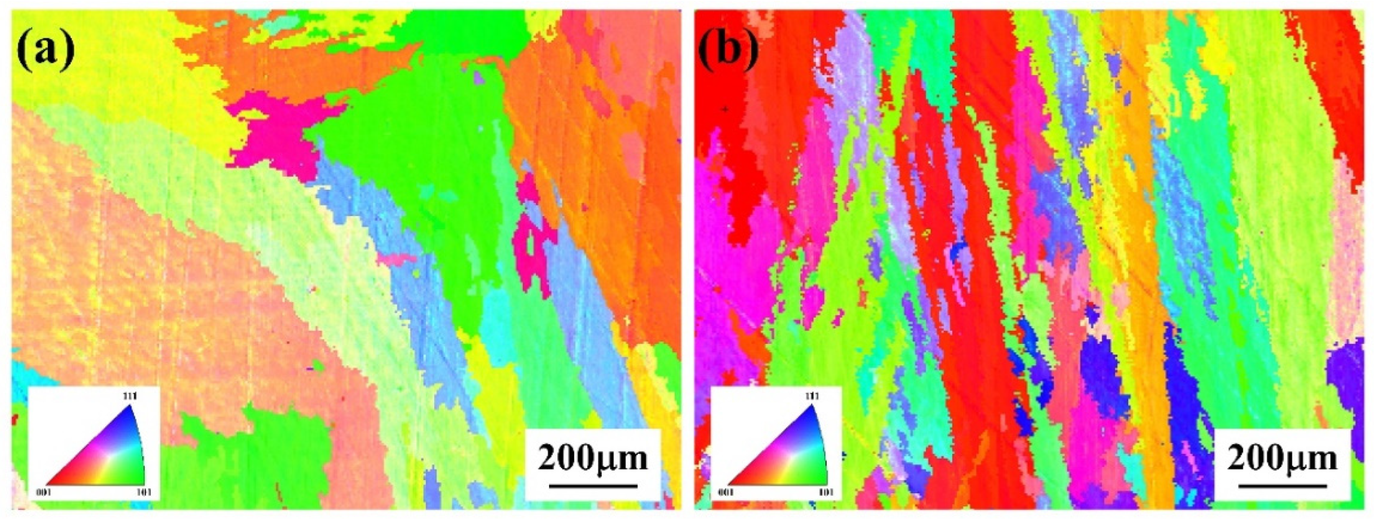
Figure 7, Figure 8 and Figure 9 depict the cross-sectional crystallographic characteristics of the N-CoCrMo and HS-CoCrMo coatings. Figure 7 presents the inverse pole figure (IPF) diagrams of these two cobalt-based alloy coatings. As shown, neither coating produced by the two processes exhibits a pronounced texture. This is attributed to the extremely high cooling rates during laser processing, which generate substantial temperature gradients between the substrate and the coating. Such large temperature gradients cause the dendrite tips to continually split, disrupting the growth along the heat flow direction and preventing the formation of a significant preferred crystallographic orientation within the coatings. The average grain sizes are 54.5 μm for the N-CoCrMo coating and 21.3 μm for the HS-CoCrMo coating, indicating a notable refinement of the grain structure in the high-speed laser-cladded sample. This grain size reduction is primarily due to the higher cooling rates associated with high-speed laser cladding, which lead to increased undercooling. This excessive undercooling exponentially increases nucleation density, thereby promoting substantial grain refinement.
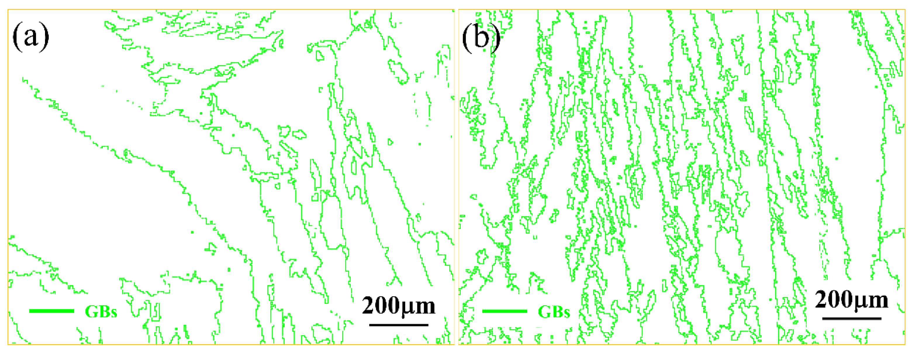
The grain boundary distribution shown in Figure 8 further confirms that the high-speed laser cladding process results in finer grains and a higher density of grain boundaries. Such an increased grain boundary density effectively hinders dislocation movement, thereby enhancing the hardness and deformation resistance of the material. Consequently, HS-CoCrMo demonstrates a stronger grain boundary strengthening effect compared to N-CoCrMo [32].
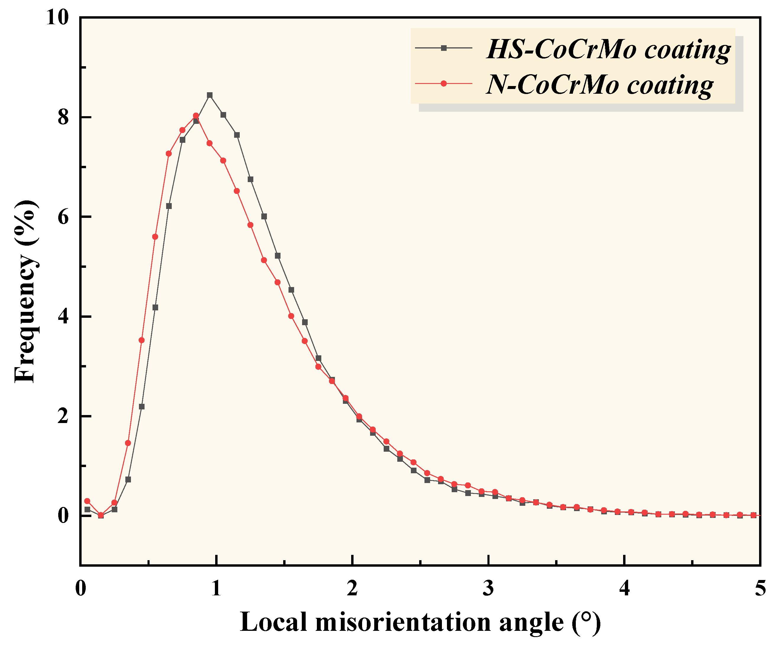
The distribution of the kernel average misorientation (KAM) at the grain boundaries of the two coatings is shown in Figure 9. The KAM values for N-CoCrMo and HS-CoCrMo are 1.17° and 1.29°, respectively. Higher KAM values indicate stronger lattice distortion and a higher accumulated dislocation density. The ultra-fast cooling rate associated with high-speed laser cladding reduces the activation energy required for dislocation creep, effectively suppressing dislocation dynamic recovery. As a result, dislocations become immobilized within the lattice, leading to a higher KAM value in the HS-CoCrMo coating. Additionally, the geometric necessary dislocation density (GND) of the two coatings can be estimated based on their KAM values, which can be calculated using the following formula [33,34]:
ρ G N D = 2 K A M a v e μ b
where μ is the EBSD step size (0.5 µm) and b is the Burgers vector (2.35 × 10⁻¹⁰). The calculated ρ G N D for the coatings is 1.99 × 10¹⁵/m−2 and 2.19 × 10¹⁵/m−2 for N-CoCrMo and HS-CoCrMo, respectively. These higher GND densities in HS-CoCrMo coatings help impede crack propagation during deformation, thereby enhancing the material’s toughness and ductility [35].

3.3. Microhardness Nano-Indentation Behavior

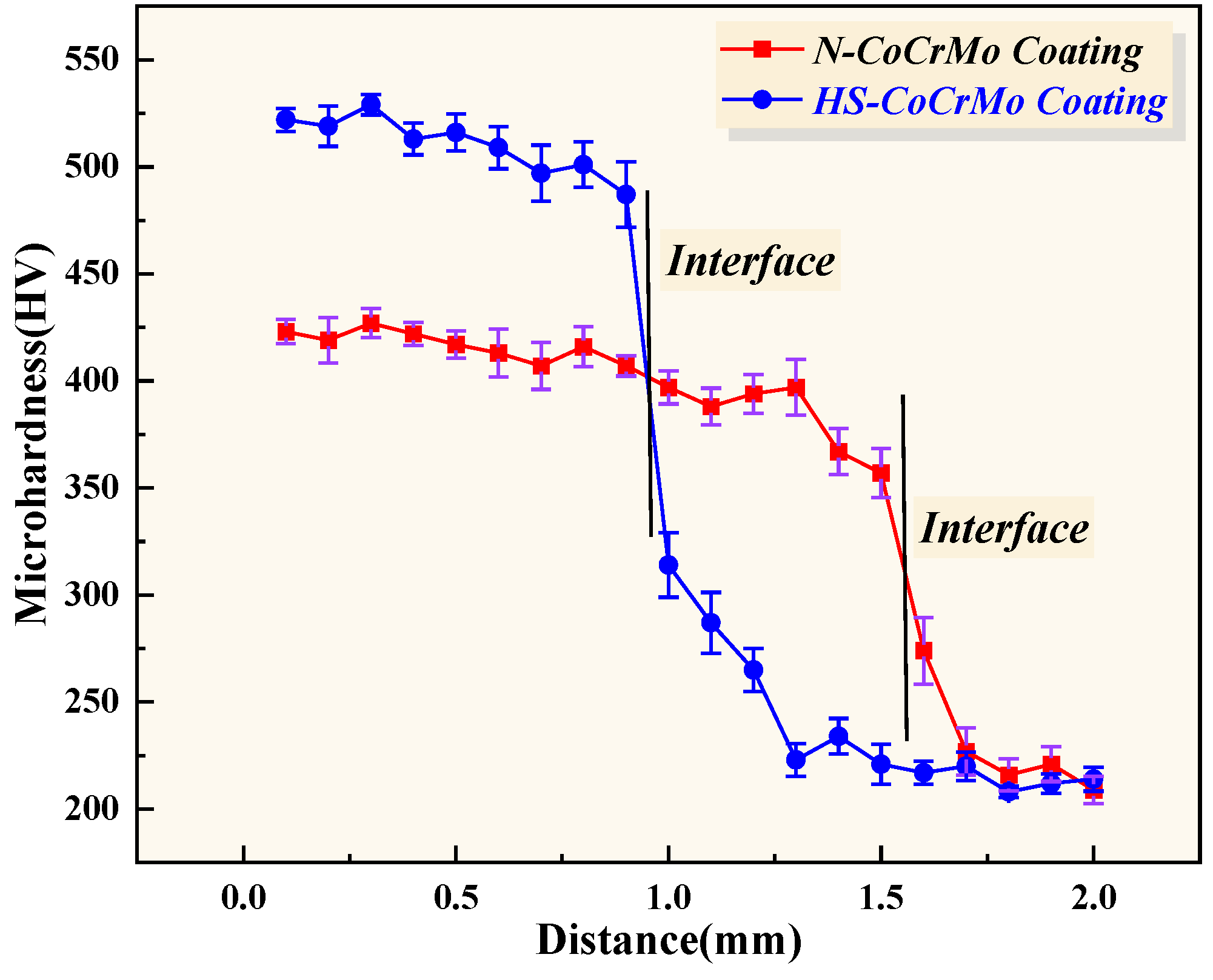
Figure 10 shows the cross-sectional microhardness profiles of the HS-CoCrMo and N-CoCrMo coatings. The results indicate that the average cross-sectional microhardness values of the HS-CoCrMo and N-CoCrMo coatings are 510 ± 8.6 HV and 403.4 ± 9.3 HV, respectively. The cross-sectional microhardness of the HS-CoCrMo coating is approximately 1.26 times higher than that of the N-CoCrMo coating. Additionally, the experimental results indicate that the microhardness of both coatings decreases to varying degrees as the test location approaches the substrate. This phenomenon is attributed to the inward diffusion of Fe elements from the substrate into the coating after the substrate melts during the laser cladding process, which consequently reduces the hardness of the coating near the interface [15].
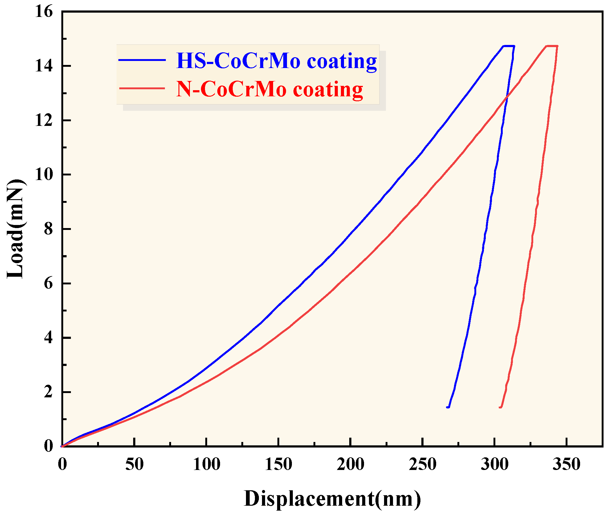
Figure 11 displays the displacement–load curves for CoCrMo alloy coatings produced by high-speed laser cladding (HS-CoCrMo) and conventional laser cladding (N-CoCrMo). The relevant parameters from the nanoindentation tests are summarized in Table 2. From these curves, it is evident that the maximum indentation depth (dmax) for the HS-CoCrMo coating is 312.83 nm, which is smaller than that of the N-CoCrMo coating at 342.96 nm. Additionally, the nano-hardness of the HS-CoCrMo coating is approximately 5.18 ± 0.23 GPa, which is about 1.22 times greater than that of the N-CoCrMo coating, indicating superior deformation resistance and hardness in the HS-CoCrMo coating [36]. This increase in nano-hardness is attributed to the combined effects of fine-grain strengthening and solid solution strengthening.
The hardness HHS of the HS-CoCrMo coating can be expressed by the following equation [37]:
HHS = H0 + HG + HS
where H0 represents the base hardness of the CoCrMo coating, HG is the hardness increment due to grain refinement, and HS is the hardness increment due to solid solution strengthening. High-speed laser cladding, with its higher cooling rate, promotes grain refinement, thereby enhancing the fine-grain strengthening effect. The effect of fine-grain strengthening is described by the Hall-Petch relationship [24]:
H d = H 0 + k d
where H 0 is the material’s initial hardness, k is a constant, and d represents the average grain size. Due to the higher cooling rate in high-speed laser cladding, the HS-CoCrMo coating has finer grains, which improves the material’s hardness and strength.
Furthermore, dislocation strengthening plays a critical role in enhancing the hardness of CoCrMo coatings. According to the KAM (Kernel Average Misorientation) results from EBSD, the dislocation density in the HS-CoCrMo coating is slightly higher than in the N-CoCrMo coating. This increased dislocation density encourages dislocation entanglement, which raises the resistance to sustained deformation, thereby increasing the material’s strength. Dislocation strengthening in the HS-CoCrMo coating can be described by Bailey’s equation [35]:
σ = σ * + M α G b ρ G N D s
where σ is the flow stress, σ is the frictional flow stress, M is the Taylor factor, G is the shear modulus, α is a constant, and b is the Burgers vector. The ρGND values for the HS-CoCrMo and N-CoCrMo coatings were calculated to be 1.99 × 10¹⁵/m−2 and 2.19 × 10¹⁵/m−2, respectively. The greater KAM value in the HS-CoCrMo coating correlates with a higher ρGND, indicating that greater stress is required for dislocation slip, enhancing the material’s strength and hardness [38].
In addition, solid solution strengthening contributes positively to hardness [39]. The XRD results in Figure 2 show significant lattice distortion in both coatings, with more pronounced distortion in the HS-CoCrMo coating, which enhances solid solution strengthening. In summary, the microhardness and nano-hardness of HS-CoCrMo coatings benefit from the combined effects of solid solution strengthening, fine-grain strengthening, and dislocation strengthening.
The nanoindentation results also correlate with the wear resistance of the coatings. Universal hardness (HU) is a key indicator of coating wear resistance, calculated as follows [40]:
H U = L m a x 26.43 d m a x 2
where Lmax is the maximum applied load (15 mN). The universal hardness of HS-CoCrMo and N-CoCrMo coatings is 0.687 GPa and 0.627 GPa, respectively, indicating that HS-CoCrMo coatings offer superior wear resistance. Additionally, the ratio of nano-hardness to elastic modulus (H/E) is an important metric for determining wear resistance. This ratio reflects the material’s load-bearing capacity under friction; the higher the H/E, the better the wear resistance [41]. The H3/E2 ratio is also used to assess plastic deformation resistance [42]. The calculated H/E and H3/E2 values for HS-CoCrMo and N-CoCrMo coatings are 0.0243 and 0.018 for H/E, and 0.0031 and 0.0015 for H3/E2, respectively, demonstrating that HS-CoCrMo coatings possess higher load-bearing capacity and resistance to plastic deformation.
Lastly, the modulus of elasticity and nano-hardness are critical for determining the coating’s resistance to crack formation [43]. The values of 1/E2H for HS-CoCrMo and N-CoCrMo coatings are listed in Table 3. Due to the high cooling rate associated with high-speed laser cladding, high residual stresses are present in the HS-CoCrMo coating, which could reduce its resistance to crack formation [44].

3.4. Wear Resistance

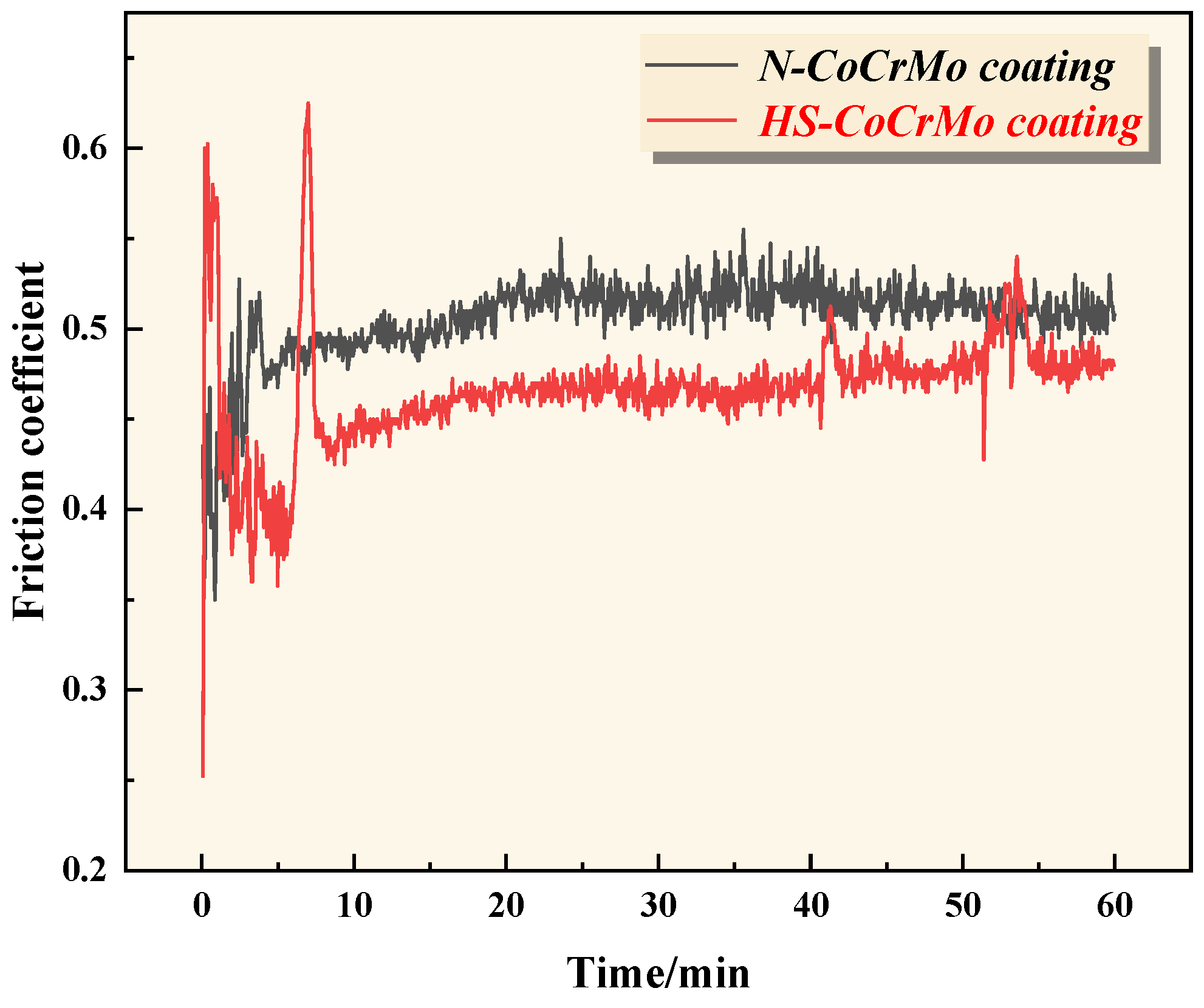
To investigate the wear resistance of N-CoCrMo and HS-CoCrMo coatings, a reciprocating friction and wear testing apparatus was used to examine the wear behavior of the two coatings. The friction coefficient versus time curves for the N-CoCrMo and HS-CoCrMo coatings are shown in Figure 12. Under dry sliding reciprocating wear for 60 min, the average friction coefficients of the N-CoCrMo and HS-CoCrMo coatings were 0.505 and 0.466, respectively. In the initial stages of wear, a high vertical load causes significant plastic deformation on the coating surfaces, leading to an increase in the friction coefficient, which is typical of dry sliding wear. As wear progresses, the friction coefficients of both coatings stabilize and gradually increase. Various factors, including surface hardness, microstructure, phase structure, and wear debris, influence the friction coefficient [45]. The higher surface hardness of the HS-CoCrMo coating reduces the detachment of coating material during wear, maintaining a smoother surface and resulting in a slightly lower friction coefficient compared to the N-CoCrMo coating. This suggests that the high-speed laser cladding process produces CoCrMo coatings with lower friction coefficients and enhanced wear resistance compared to conventional laser cladding.
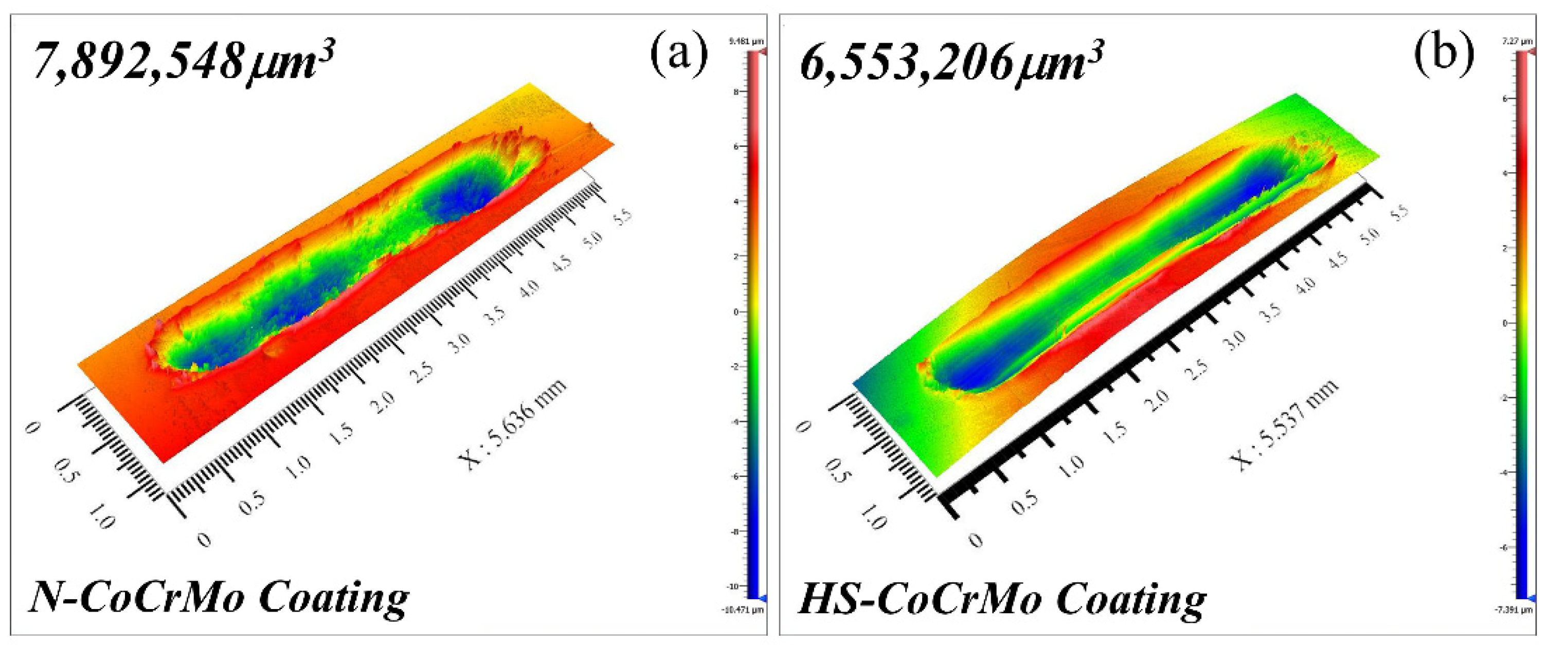
Figure 13 presents the three-dimensional wear morphology of the N-CoCrMo and HS-CoCrMo coatings, with wear volumes measured using white light interferometry. The wear volumes of the N-CoCrMo and HS-CoCrMo coatings were 7.89 × 106 μm3 and 6.55 × 106 μm3, respectively, indicating a 17% reduction in wear volume for the HS-CoCrMo coating. Specific wear rate, another key metric for evaluating coating wear performance, is given by the following formula [46]:
V s = V F · L
where V is the wear volume, F is the applied load, and L is the wear distance. The lower specific wear rate for the HS-CoCrMo coating, 0.87 × 10⁻⁵ mm3/N·m, compared to 1.05 × 10⁻⁵ mm3/N·m for the N-CoCrMo coating, confirms its improved wear resistance. Additionally, the H/E and H3/E2 values from nanoindentation tests further indicate the superior wear resistance of the HS-CoCrMo coating.
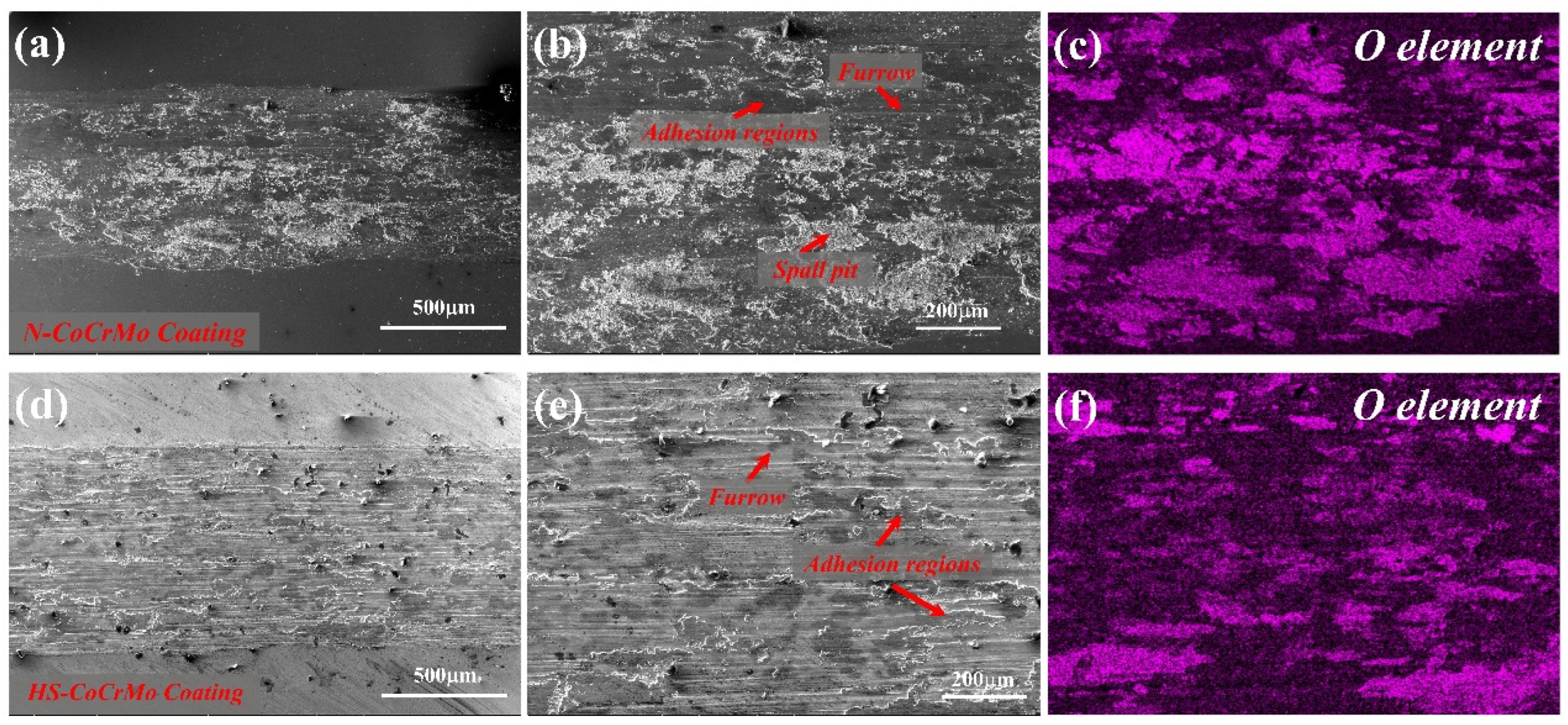
To better understand the wear mechanisms, the wear morphology of both coatings was examined using scanning electron microscopy (SEM), and the oxygen distribution on the wear surfaces was analyzed using EDS (Figure 14). The wear morphology of the N-CoCrMo coating revealed significant abrasion marks, deep furrows, plastic deformation, and extensive spalling. These features suggest that during dry sliding friction, the N-CoCrMo coating undergoes strong cutting action. The relatively low cooling rate during its production results in coarser grains with lower hardness and homogeneity, making the coating prone to forming micro-fusion zones under high temperatures and loads. With increased shear force, these adhesion zones pull apart, causing the coating to flake, creating deep adhesive and spalling marks on the wear surface. The lower hardness also exacerbates adhesive wear, with the detached debris hardening and embedding into the surface, leading to abrasive-like particles. These particles contribute to severe plastic deformation and form deep, dense furrows. Conversely, the higher cooling rate in HS-CoCrMo coatings results in finer, more uniformly distributed grains. Solid solution strengthening and dislocation strengthening also enhance the hardness of the HS-CoCrMo coating, reducing the formation of adhesion zones. Due to the coating’s dense microstructure and high hardness, adhesion zones are less likely to separate under shear stress, leaving only slight adhesion marks in the wear pattern. Additionally, the improved hardness minimizes the cutting and plowing effects of abrasive particles [47]. This results in shallower plough grooves, a more uniform surface, and fewer spalling areas, indicating superior abrasive wear resistance in the HS-CoCrMo coating.
Furthermore, Figure 14c illustrates the oxygen element distribution on the N-CoCrMo coating, showing a higher oxide concentration on the wear surface. This is attributed to the coarser grains and lower hardness of the N-CoCrMo coating, which make it more susceptible to localized high temperatures during friction, increasing the likelihood of oxidation and oxide film formation [48]. The brittle oxide film fractures easily, with broken oxide particles embedding in the wear surface, intensifying abrasive wear. In contrast, the HS-CoCrMo coating exhibits a uniform but low concentration of oxygen, indicating reduced oxide formation. The rapid cooling rate in high-speed laser cladding produces finer, more uniform grains with higher hardness, reducing oxidation under localized high temperatures. Even at high friction loads, only minimal oxide films form, minimizing oxidized debris and the potential for abrasive wear. In conclusion, the wear mechanisms for both N-CoCrMo and HS-CoCrMo coatings involve abrasive, adhesive, and oxidative wear. However, the finer grain size and higher hardness of the HS-CoCrMo coating contribute to its superior wear resistance.

4. Conclusions

In this study, the HS-CoCrMo coatings prepared via high-speed laser cladding technology exhibited significantly superior microstructure, hardness, and wear resistance compared to the N-CoCrMo coatings produced using traditional laser cladding methods.
(1) Both CoCrMo coatings derived from the two preparation processes consist of γ-Co and ε-Co phases. The HS-CoCrMo coating, due to its higher cooling rate, displays finer and more uniformly distributed grains, along with an increased dislocation density. The finer grains markedly enhance the grain boundary strengthening effect, while the elevated dislocation density contributes further to the overall mechanical performance.
(2) The nano-hardness of the HS-CoCrMo coating reaches 5.18 ± 0.23 GPa, approximately 22% higher than that of the conventional laser cladding (N-CoCrMo) coating. This hardness enhancement is attributed to the synergistic effects of grain refinement strengthening, solid solution strengthening, and dislocation strengthening.
(3) The HS-CoCrMo coating also demonstrates superior wear resistance, as indicated by higher HU, H/E, and H3/E2 values, which reflect improved resistance to plastic deformation and fatigue wear. Friction and wear tests show that the HS-CoCrMo coating has a lower average coefficient of friction, with approximately 17% reduction in wear volume and approximately 18% decrease in specific wear rate, indicating enhanced wear strength and resistance to failure under abrasive conditions. The primary wear mechanisms of the HS-CoCrMo coating involve abrasive and adhesive wear, with minor oxidation wear observed.

Author Contributions

Investigation, T.W., Q.L., F.H. and H.C.; writing—review & editing, T.W.; funding acquisition and data curation. T.X., Q.L., F.H. and H.C.; supervision and methodology, T.X. All authors have read and agreed to the published version of the manuscript.

Funding

The authors gratefully acknowledge the financial support for this research from the National Key Research and Development Program of China (No. 2023YFB4606605) and the National Natural Science Foundation of China (No. 52077121).

Institutional Review Board Statement

Not applicable.

Informed Consent Statement

Not applicable.

Data Availability Statement

No data were used for the research described in the article.

Conflicts of Interest

Author Qingquan Li, Fengping Huo and Haitao Chen were employed by the Shenyang Dalu Laser Technology Co., Ltd. The remaining authors declare that the research was conducted in the absence of any commercial or financial relationships that could be construed as a potential conflict of interest.

References

  1. Jian, Y.; Liu, Y.; Qi, H.; He, P.; Huang, G.; Huang, Z. Effects of scanning speed on the microstructure, hardness and corrosion properties of high-speed laser cladding Fe-based stainless coatings. J. Mater. Res. Technol. 2024, 29, 3380–3392. [Google Scholar] [CrossRef]
  2. Wang, X.; Ren, X.; Xue, Y.; Luan, B. Investigation on microstructure and high-temperature wear properties of high-speed laser cladding Inconel 625 alloy. J. Mater. Res. Technol. 2024, 30, 626–639. [Google Scholar] [CrossRef]
  3. Xu, J.; Zhou, L.; Ma, G.; Li, G.; Zhao, H.; Wang, H. Microstructure and excellent arc ablation resistance of Ni–8Al coating on copper substrate by high-speed laser cladding. J. Mater. Res. Technol. 2024, 31, 606–617. [Google Scholar] [CrossRef]
  4. Wei, R.; Mao, M.; Liang, J.; Zhao, C.; Ouyang, C.; Bai, Q. Repair feasibility and performance enhancement analysis of Fe-based alloy coating on ductile iron surface by high-speed laser cladding. Mater. Today Commun. 2024, 39, 108638. [Google Scholar] [CrossRef]
  5. Bu, X.; Xu, X.; Lu, H.; Liang, Y.; Bian, H.; Luo, K.; Lu, J. Effect of overlap rate on the microstructure and properties of Cr-rich stainless steel coatings prepared by extreme high-speed laser cladding. Surf. Coat. Technol. 2024, 487, 131025. [Google Scholar] [CrossRef]
  6. Du, J.L.; Deng, W.W.; Xu, X.; Wu, Y.J.; Luo, K.Y.; Zhang, H.M.; Lu, J.Z. Improvement of microstructure and performance of an extreme-high-speed laser cladding CoCrFeMnNi coating through laser shock peening. J. Alloys Compd. 2024, 1002, 175520. [Google Scholar] [CrossRef]
  7. Fu, J.; Gui, W.; Qin, J.; Lin, J.; Ren, X.; Luan, B. High-speed laser-clad 3533-00 Fe-based cemented carbide coatings on nuclear power valve sealing surface to enhanced wear and corrosion resistance. Surf. Coat. Technol. 2024, 480, 130594. [Google Scholar] [CrossRef]
  8. Wang, H.; Cheng, Y.; Wan, Y.; Jeyaprakash, N.; Wang, Y.; Ma, K.; Yang, J. Influence of scanning speed on microstructure and corrosion resistance of Fe-based amorphous coatings by high-speed laser cladding. Surf. Coat. Technol. 2024, 479, 130449. [Google Scholar] [CrossRef]
  9. Yu, Y.; Li, Y.; Tan, N.; Mou, H.; Tong, Y.; Xing, Z.; Cai, Z.; Wang, H. Influence of cBN on the microstructure and tribology properties of (CoCrNi)94Al3Ti3 medium-entropy alloy coating prepared by high-speed laser cladding: The evolution and strengthening mechanism of cBN. Ceram. Int. 2024, 50, 22041–22049. [Google Scholar] [CrossRef]
  10. An, Y.; Pang, X.; Liu, G.; Zheng, S.; Wang, Y.; Pu, J. Effect of h-BN on corrosion behavior of nickel-copper alloy coatings prepared by high-speed laser cladding. J. Mater. Res. Technol. 2024, 28, 4065–4075. [Google Scholar] [CrossRef]
  11. Chen, C.; Bai, Q.; Zhao, C.; Li, Q.; Zhang, S. Effect of ultrasonic high-frequency micro-forging on the wear resistance of a Fe-base alloy coating deposited by high-speed laser cladding process. Vacuum 2024, 221, 112934. [Google Scholar] [CrossRef]
  12. Liu, J.; Cui, X.; Jin, G.; Wen, X.; Li, D.; Jing, Y.; Li, Y.; Qi, Y. A novel strategy for preparation of ZrB2–SiC self-transpiration cooling coating by dilution effect of high speed laser cladding. Ceram. Int. 2024, 50, 18075–18079. [Google Scholar] [CrossRef]
  13. Georgiou, E.P.; Drees, D.; Timmermans, G.; Zoikis-Karathanasis, A.; Pérez-Fernández, M.; Magagnin, L.; Celis, J.-P. High performance accelerated tests to evaluate hard Cr replacements for hydraulic cylinders. Coatings 2021, 11, 1511. [Google Scholar] [CrossRef]
  14. Liang, Y.; Liao, Z.Y.; Zhang, L.L.; Cai, M.W.; Wei, X.S.; Shen, J. A review on coatings deposited by extreme high-speed laser cladding: Processes, materials, and properties. Opt. Laser Technol. 2023, 164, 109472. [Google Scholar] [CrossRef]
  15. Lv, H.; Liu, Y.; Chen, H.; Zhang, W.; Lv, S.; He, D. Temperature field simulation and microstructure evolution of Fe-based coating processed by extreme high-speed laser cladding for re-manufacturing locomotive axle. Surf. Coat. Technol. 2023, 464, 129529. [Google Scholar] [CrossRef]
  16. Yuan, W.; Li, R.; Chen, Z.; Gu, J.; Tian, Y. A comparative study on microstructure and properties of traditional laser cladding and high-speed laser cladding of Ni45 alloy coatings. Surf. Coat. Technol. 2021, 405, 126582. [Google Scholar] [CrossRef]
  17. Yang, J.; Bai, B.; Ke, H.; Cui, Z.; Liu, Z.; Zhou, Z.; Xu, H.; Xiao, J.; Liu, Q.; Li, H. Effect of metallurgical behavior on microstructure and properties of FeCrMoMn coatings prepared by high-speed laser cladding. Opt. Laser Technol. 2021, 144, 107431. [Google Scholar] [CrossRef]
  18. Du, J.L.; Xu, X.; Zhang, H.M.; Lu, M.W.; Sun, J.F.; Luo, K.Y.; Lu, J.Z. Microstructure and wear resistance of CoCrFeNiMn coatings prepared by extreme-high-speed laser cladding. Surf. Coat. Technol. 2023, 470, 129821. [Google Scholar] [CrossRef]
  19. Li, C.; Liu, Z.; Huang, F.; Dong, J.; Wang, C.; Yuan, J.; Fu, Q. Experimental study of corrosion resistance of 431M2 stainless steel coatings in a CO2-saturated NaCl solution deposited by extreme high-speed laser cladding. Mater. Today Commun. 2024, 38, 108202. [Google Scholar] [CrossRef]
  20. Zhang, W.; Liu, Y.; Hu, D.; Lv, H.; Yang, Q. Experimental and numerical simulation studies of the flow characteristics and temperature field of Fe-based powders in extreme high-speed laser cladding. Opt. Laser Technol. 2024, 170, 110317. [Google Scholar] [CrossRef]
  21. Cui, C.; Wu, M.; Miao, X.; Gong, Y.; Zhao, Z. The effect of laser energy density on the geometric characteristics, microstructure and corrosion resistance of Co-based coatings by laser cladding. J. Mater. Res. Technol. 2021, 15, 2405–2418. [Google Scholar] [CrossRef]
  22. Smoqi, Z.; Toddy, J.; Halliday, H.; Shield, J.E.; Rao, P. Process-structure relationship in the directed energy deposition of cobalt-chromium alloy (Stellite 21) coatings. Mater. Des. 2021, 197, 109229. [Google Scholar] [CrossRef]
  23. Zhang, N.; Xu, Y.-f.; Wang, M.-h.; Hou, X.-d.; Du, B.-r.; Ge, X.-y.; Shi, H.; Xie, X. M2 coating prepared by ultra-high speed laser cladding: Microstructure and interfacial residual stress. Mater. Today Commun. 2023, 35, 105638. [Google Scholar] [CrossRef]
  24. Xu, T.Z.; Zhang, S.; Wang, L.; Du, Y.; Wu, C.L.; Zhang, C.H.; Sun, X.Y.; Chen, H.T.; Chen, J. Influence of scanning speed on the microstructure, nanoindentation characteristics and tribological behavior of novel maraging steel coatings by laser cladding. Mater. Charact. 2023, 205, 113335. [Google Scholar] [CrossRef]
  25. Verchère, L.; Aubert, I.; Devos, O. Influence of the crystallographic orientation on the electrochemical reactivity measured by Scanning Electrochemical Microscopy on nickel-based alloy 600. Electrochim. Acta 2019, 313, 292–302. [Google Scholar] [CrossRef]
  26. Wu, T.; Degener, S.; Tinkloh, S.; Liehr, A.; Zinn, W.; Nobre, J.P.; Tröster, T.; Niendorf, T. Characterization of residual stresses in fiber metal laminate interfaces—A combined approach applying hole-drilling method and energy-dispersive X-ray diffraction. Compos. Struct. 2022, 299, 116071. [Google Scholar] [CrossRef]
  27. Wang, H.; An, Y.; Xu, X.; Guo, X.; Hu, Y. Rapid solidification microstructure evolution and grain refinement of deeply undercooled nickel alloys. Mater. Charact. 2020, 170, 110703. [Google Scholar] [CrossRef]
  28. Limmaneevichitr, C.; Kou, S. Experiments to simulate effect of Marangoni convection on weld pool shape. Weld. J. 2000, 79, 231-237-S. [Google Scholar]
  29. Liang, Y.-J.; Cheng, X.; Li, J.; Wang, H.-M. Microstructural control during laser additive manufacturing of single-crystal nickel-base superalloys: New processing–microstructure maps involving powder feeding. Mater. Des. 2017, 130, 197–207. [Google Scholar] [CrossRef]
  30. Shi, L.; Jiang, L.; Gao, M. Numerical research on melt pool dynamics of oscillating laser-arc hybrid welding. Int. J. Heat Mass Transf. 2022, 185, 122421. [Google Scholar] [CrossRef]
  31. Kobayashi, Y.; Dobara, K.; Todoroki, H.; Nam, C.; Morishita, K.; Yasuda, H. In-Situ Measurements of Solute Partition Coefficients Between Solid and Liquid Phases in Fe–Cr–Ni–Mo–Cu Alloys During Solidification. ISIJ Int. 2020, 60, 276–285. [Google Scholar] [CrossRef]
  32. Fu, K.; Zhong, C.; Zhang, L.; Wang, X.; Nie, B.; Xue, Y.; Gui, W.; Luan, B. Effect of multiple thermal cycling on the microstructure and microhardness of Inconel 625 by high-speed laser cladding. J. Mater. Res. Technol. 2023, 24, 1093–1107. [Google Scholar] [CrossRef]
  33. TXu, Z.; Zhang, S.; Du, Y.; Wu, C.L.; Zhang, C.H.; Sun, X.Y.; Chen, H.T.; Chen, J. Development and characterization of a novel maraging steel fabricated by laser additive man-ufacturing. Mater. Sci. Eng. A 2024, 891, 145975. [Google Scholar]
  34. Xu, T.Z.; Wang, T.; Wang, M.S.; Zhang, S.; Zhang, C.H.; Wu, C.L.; Sun, X.Y.; Chen, H.T.; Chen, J. Influence of solid solution time on microstructure and precipitation strengthening of novel maraging steels. Mater. Sci. Eng. A 2025, 920, 147535. [Google Scholar]
  35. Kubin, L.P.; Mortensen, A. Geometrically necessary dislocations and strain-gradient plasticity: A few critical issues. Scr. Mater. 2003, 48, 119–125. [Google Scholar] [CrossRef]
  36. Xu, T.Z.; Wang, T.; Wang, R.; Zhang, S.; Zhang, C.H.; Wu, C.L.; Sun, X.Y.; Chen, H.T.; Chen, J. Influence of various heat treatment processes behavior of a novel maraging steel coating process on the microstructure, nanoindentation pattern, and wear. Surf. Coat. Technol. 2024, 487, 130984. [Google Scholar] [CrossRef]
  37. Xu, T.Z.; Zhang, S.; Wang, Z.Y.; Zhang, C.H.; Zhang, D.X.; Wang, M.; Wu, C.L. Wear behavior of graphite self-lubricating Babbitt alloy composite coating on 20 steel prepared by laser cladding. Eng. Fail. Anal. 2022, 141, 106698. [Google Scholar] [CrossRef]
  38. Li, K.; Zhan, J.; Yang, T.; To, A.C.; Tan, S.; Tang, Q.; Cao, H.; Murr, L.E. Homogenization timing effect on microstructure and precipitation strengthening of 17–4PH stainless steel fabricated by laser powder bed fusion. Addit. Manuf. 2022, 52, 102672. [Google Scholar] [CrossRef]
  39. Zhang, Z.; Chen, D. Consideration of Orowan strengthening effect in particulate-reinforced metal matrix nanocomposites: A model for predicting their yield strength. Scr. Mater. 2006, 54, 1321–1326. [Google Scholar] [CrossRef]
  40. Li, N.; Wang, Q.; Niu, W.; Han, P.; Guo, N.; Li, S. Microstructure and wear behaviors of 17-4 PH stainless steel fabricated by laser cladding with post laser shock peening treatment. Wear 2024, 538, 205207. [Google Scholar] [CrossRef]
  41. Roy, M.; Whiteside, L.; Xu, J.; Katerberg, B. Diamond-like carbon coatings enhance the hardness and resilience of bearing surfaces for use in joint arthroplasty. Acta Biomater. 2010, 6, 1619–1624. [Google Scholar] [CrossRef]
  42. Leyland, A.; Matthews, A. On the significance of the H/E ratio in wear control: A nanocomposite coating approach to optimised tribological behaviour. Wear 2000, 246, 1–11. [Google Scholar] [CrossRef]
  43. Sha, C.; Zhou, Z.; Xie, Z.; Munroe, P. High entropy alloy FeMnNiCoCr coatings: Enhanced hardness and damage-tolerance through a dual-phase structure and nanotwins. Surf. Coat. Technol. 2020, 385, 125435. [Google Scholar] [CrossRef]
  44. Guan, S.; Wan, D.; Solberg, K.; Berto, F.; Welo, T.; Yue, T.M.; Chan, K. Additive manufacturing of fine-grained and dislocation-populated CrMnFeCoNi high entropy alloy by laser engineered net shaping. Mater. Sci. Eng. A 2019, 761, 138056. [Google Scholar] [CrossRef]
  45. Deng, G.; Tieu, A.K.; Su, L.; Wang, P.; Wang, L.; Lan, X.; Cui, S.; Zhu, H. Investigation into reciprocating dry sliding friction and wear properties of bulk CoCrFeNiMo high entropy alloys fabricated by spark plasma sintering and subsequent cold rolling processes: Role of Mo element concentration. Wear 2020, 460, 203440. [Google Scholar] [CrossRef]
  46. Miao, J.; Guo, T.; Ren, J.; Zhang, A.; Su, B.; Meng, J. Optimization of mechanical and tribological properties of FCC CrCoNi multi-principal element alloy with Mo addition. Vacuum 2018, 149, 324–330. [Google Scholar] [CrossRef]
  47. Popov, V. Generalized archard law of wear based on rabinowicz criterion of wear particle formation. Facta Univ. Ser. Mech. Eng. 2019, 17, 39–45. [Google Scholar] [CrossRef]
  48. Telliskivi, T. Simulation of wear in a rolling–sliding contact by a semi-Winkler model and the Archard’s wear law. Wear 2004, 256, 817–831. [Google Scholar] [CrossRef]
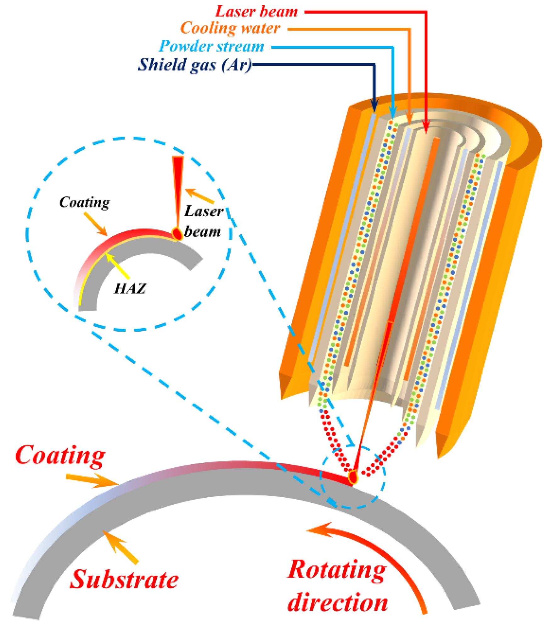
Figure 1. Schematic diagram of high-speed laser cladding.
Coatings 15 01200 g001
Figure 2. XRD diffraction patterns of HS-CoCrMo and N-CoCrMo coatings. (a) 30–100°; (b) 42–45°.
Coatings 15 01200 g002
Figure 3. Cross-sectional macroscopic morphology of N-CoCrMo and HS-CoCrMo coatings: (a,b) Single-pass cross-sectional morphology of the coatings; (c,d) macroscopic morphology of multi-pass overlap sections of the coatings.
Coatings 15 01200 g003
Figure 4. Microstructural morphology of N-CoCrMo and HS-CoCrMo coatings: (ac) Microstructure of N-CoCrMo coating; (df) Microstructure of HS-CoCrMo coating; (g) Schematic diagram of temperature gradient and solidification rate vs. crystal morphology.
Coatings 15 01200 g004
Figure 5. Microstructure and elemental distribution of N-CoCrMo coating.
Coatings 15 01200 g005
Figure 6. Microstructure and elemental distribution of HS-CoCrMo coating.
Coatings 15 01200 g006
Figure 7. IPF Plots of N-CoCrMo Coatings and HS-CoCrMo Coatings. (a) N-CoCrMo coating; (b) HS-CoCrMo coating.
Coatings 15 01200 g007
Figure 8. Grain boundary distribution map of N-CoCrMo coating and HS-CoCrMo coating. (a) N-CoCrMo coating; (b) HS-CoCrMo coating.
Coatings 15 01200 g008
Figure 9. KAM line plot of N-CoCrMo coating and HS-CoCrMo coating.
Coatings 15 01200 g009
Figure 10. Curve of cross-section microhardness with depth for N-CoCrMo coating and HS-CoCrMo coating.
Coatings 15 01200 g010
Figure 11. Displacement–load curves of N-CoCrMo coating and HS-CoCrMo coating.
Coatings 15 01200 g011
Figure 12. Curve of friction coefficient with time for N-CoCrMo coating and HS-CoCrMo coating.
Coatings 15 01200 g012
Figure 13. The 3D wear topography of N-CoCrMo coating and HS-CoCrMo coating. (a) N-CoCrMo coating; (b) HS-CoCrMo coating.
Coatings 15 01200 g013
Figure 14. Wear morphology and elemental distribution of N-CoCrMo coating and HS-CoCrMo coating. (ac) N-CoCrMo coating; (df) HS-CoCrMo coating.
Coatings 15 01200 g014
Table 1. The nominal chemical composition of CoCrMo alloy powder.
ElementCSiMnCrNiMoCoFe
Wt%0.351.01.026.51.04.5Bal.1.0
Table 2. The process parameters of conventional laser cladding and high-speed laser cladding.
SampleLaser
Power (W)
Scanning
Speed (m/min)
Laser Spot Diameter (mm)Overlapping
Rate
Powder
Flow Rate
(g/min)
HS-CoCrMo20001350%16
N-CoCrMo28003370%24
Table 3. The nano-hardness and elastic modulus are significant parameters for the wear resistance of metallic materials.
SampleH (GPa)E (GPa)dmax (nm)HU (GPa)H/EH3/E21/E2H(Gpa−3) × 106
HSLC5.18 ± 0.23213.367312.830.6870.02430.00314.255
LC4.22 ± 0.17226.459342.960.6270.01870.00154.640
Disclaimer/Publisher’s Note: The statements, opinions and data contained in all publications are solely those of the individual author(s) and contributor(s) and not of MDPI and/or the editor(s). MDPI and/or the editor(s) disclaim responsibility for any injury to people or property resulting from any ideas, methods, instructions or products referred to in the content.