Article

Polypyrrole-Modified Molybdenum Disulfide Nanocomposite Epoxy Coating Inhibits Corrosion of Mild Steel

1
School of Materials Science and Engineering, Hainan University, Haikou 570228, China
2
State Key Laboratory of Marine Resource Utilization in South China Sea, Hainan University, Haikou 570228, China
3
Hainan Yazhou Bay Seed Laboratory, Sanya Nanfan Research Institute of Hainan University, Sanya 572025, China
*
Authors to whom correspondence should be addressed.
Coatings 2023, 13(6), 1046; https://doi.org/10.3390/coatings13061046
Submission received: 16 April 2023 / Revised: 26 May 2023 / Accepted: 2 June 2023 / Published: 5 June 2023
(This article belongs to the Section Corrosion, Wear and Erosion)

Abstract

:
The search for lightweight and low-cost anticorrosion coatings is particularly important in coastal environments with high salt and humidity. Graphene-based anticorrosion coatings are currently unable to provide long-lasting corrosion protection for metals because of their “corrosion-promoting activity”, and graphene-like materials, such as molybdenum disulfide (MoS2), are beginning to be anticipated its ability to protect against metals. This paper reported a simple method for preparing polypyrrole (PPy)-modified MoS2 nanomaterials from natural bulk MoS2. Their corrosion resistance behavior as fillers for epoxy (EP) resins was investigated in 3.5 wt.% NaCl solution. After the preparation of the MoS2 nanosheet dispersion by liquid-phase sonication using ethanol aqueous solution, the polypyrrole-coated molybdenum disulfide nanomaterials (MoS2@PPy) were directly obtained by adding pyrrole monomer to it in the presence of the initiator ammonium persulfate. Tafel polarization curves showed that the corrosion current of the MoS2@PPy/EP coating was 0.006 µA/cm2 after 15 days of immersion in 3.5 wt.% NaCl solution, much lower than that of pure EP coating (19.134 µA/cm2), effectively improving the anticorrosive properties of the coating. Overall, this study offered a practical method for the application of natural bulk MoS2 for corrosion protection.

1. Introduction

Corrosion was long an obstacle to the development of coastal areas and the construction of offshore facilities. Therefore, the development of marine resources requires simple and effective methods to delay the occurrence of corrosion in metallic facilities. Epoxy resins are environmentally friendly coatings due to their excellent chemical resistance, high adhesion and friction resistance, and low volatile organic compounds (VOC) content, and are widely used in transportation, electronic facilities, and infrastructure [1]. Despite the advantages of epoxy resins, defects such as microcracks and microporosity inevitably occur during the curing process of the coating, and also ages and degrades itself to produce defects under coastal conditions of high temperature and humidity [2]. This makes it impossible to isolate the corrosive media (Cl, O2) in the long term, leading to corrosion at the metal interface, resulting in epoxy coating peeling and protection failure [3].
Studies showed that the use of nanofillers can effectively improve the corrosion resistance and mechanical properties of epoxy coatings [4], where two-dimensional nanomaterial fillers (graphene-oxide [5], molybdenum disulfide [6], boron nitride [7], lamellar hydroxide [8], mica [9]) are beginning to receive attention from researchers. Using graphene nanosheets as fillers, they can act as barriers and obstacles to block micro-pores and defects in the coating matrix, delaying the penetration of corrosive media into the metal interface, effectively improving the corrosion resistance of epoxy resins and beginning to be used in the market [10]. However, graphene due to its own zero band gap qualities, resulting in the coating cracking, graphene will behave as “corrosion-promoting activity”, accelerate the corrosion of the proceeding, and cannot have a long-lasting anti-corrosion effect [11,12].
Recently, there was great interest in transition metal sulfide TMDs (e.g., MoS2, WS2, etc.), which have many of the same properties as graphene materials, while having relatively low electrical conductivity, which is beneficial for anticorrosion applications [13,14]. At the same time, MoS2 is an abundant mineral in nature, its nanosheets can be obtained on a large scale by simple liquid phase sonication and ball milling, and the development of MoS2 for corrosion protection is also conducive to the comprehensive development and utilization of molybdenum resources. Among them, MoS2 has excellent mechanical properties, chemical resistance, and an ultra-thin layer structure [15], and unlike graphene, it is a high bandgap semiconductor material that has no effect on the electrical conductivity of epoxy resins and does not cause “corrosion-promoting activity”, which started to receive attention in the field of corrosion protection [16]. Xia et al. modified MoS2 with dopamine and added it to epoxy resin by introducing catechol-OH group and amino group, which greatly improved the adhesion of epoxy resin [17]; Chen et al. modified MoS2 with silica, which enhanced its compatibility with epoxy resin and greatly improved the corrosion resistance of epoxy resin [18]; Ding et al. noted that the power function of MoS2 less layer structure (4.5 eV) is lower than that of iron (4.73 eV) compared to that of monolayer MoS2 (5.26 eV), which causes the formation of the Schottky barrier (n-type barrier) in the anticorrosion process and is more favorable for anticorrosion applications [19]; Tang et al. noted that transition metal sulfides such as MoS2 can be strongly coordinated with polyaniline, nitrogen in PPy atoms for strong coordination [20]. Meanwhile, the conductive polymer PPy, as an anticorrosive coating, has a unique molecular structure that can induce metal passivation to play an anticorrosive role [21].
Therefore, in this paper, few-layer MoS2 nanosheets were prepared by liquid-phase ultrasonication, while Py monomer were polymerized and modified on the surface of MoS2 using chemical oxidation, and then the prepared composite MoS2@PPy was added to epoxy resin to improve its corrosion resistance, and the composite was characterized using SEM, UV–Vis spectroscopy, XRD, and FT-IR, and its corrosion resistance was evaluated using EIS, Tafel, and Neutral salt spray test was performed to evaluate the corrosion resistance.

2. Materials and Methods

2.1. Materials

Molybdenum disulfide (MoS2, ≥99.5%, AR), anhydrous ethanol (C2H5OH, ≥99.5%, AR), pyrrole monomer (Py, ≥99.5%, AR), and ammonium persulfate ((NH4)2S2O8, ≥99.5%, AR) were purchased from Maclean’s (Shanghai, China). Epoxy resin (E51) was purchased from Yoshida Chemical Co. (Shenzhen, China), polyamide (D230) was purchased from Runxiang Chemical Co. (Changzhou, China). The deionized water used during the experiments was homemade in an ultrapure water machine (Direct-Q3UV, MERCK, Darmstadt, Germany) and all reagents were used directly without further purification treatment.

2.2. Experimental Method

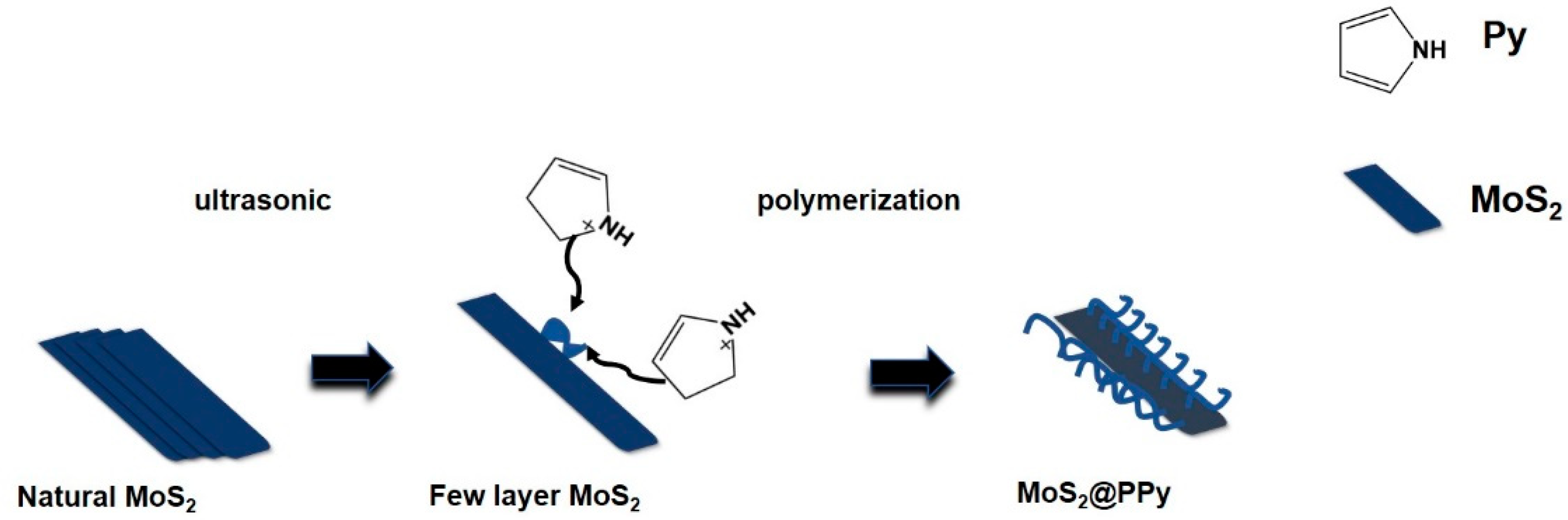
2.2.1. Synthesis of MoS2 Nanosheets

An amount of 2 g of bulk MoS2 was added to a beaker containing 200 mL of ethanol aqueous solution (45%) [22], and it was sonicated for a certain time at room temperature using an ultrasonic cleaner. After sonication, it was centrifuged using 4500 rpm rotation for 30 min to remove the unexfoliated block, and then 4/5 of the supernatant after centrifugation was collected, 5 mL of ammonia was added dropwise to the supernatant, stirred for 8 min, the precipitate was centrifuged using a centrifuge using 4000 rpm, and the obtained precipitate was placed in water and ultrasonically dispersed for 30 min to obtain a dark green solution, which was frozen overnight and then freeze-dried for 48 h to obtain a silver gray MoS2 powder.

2.2.2. Synthesis of PPy

We added 400 µL of Py monomer to a beaker containing 400 mL of aqueous ethanol solution and dispersed by ultrasound for 30 min, we then added 1.6 mL of ammonium persulfate (0.41 g/mL) dropwise to the mixture while stirring. The reaction was kept under ice bath conditions for 12 h to obtain a black suspension. The suspension was filtered under vacuum to obtain a black sample. The sample was washed three times with ethanol and water to remove unreacted material and lyophilised to obtain black PPy powder.

2.2.3. Synthesis of MoS2@PPy Nanomaterials

The MoS2 suspension (the solvent was 45% ethanol aqueous solution) was sonicated for 4 h by using an ultrasonic cleaner, and then 3/4 of the supernatant was taken by centrifugation at 4500 rpm for 25 min. The concentration of the MoS2 nanosheet dispersion was controlled at 1 mg/mL by UV–Vis spectroscopy, and Py (400 µL) and 1.6 mL of (NH4)2S2O8 aqueous solution (0.41 g/mL) were added sequentially to 400 mL of the MoS2 dispersion. The reaction was stirred under ice bath conditions for 12 h. The mixture was then filtered under vacuum, washed with ethanol and water sequentially to remove the unreacted Py, and lyophilized to obtain MoS2@PPy powder.

2.2.4. Preparation of MoS2/EP Coating and MoS2@PPy EP Coating

The prepared MoS2 nanosheets and MoS2@PPy were added to EP resin in proportion (Table 1). After mechanical stirring and mixing, the mixture was ultrasonicated for 30 min. Then, the curing agent was added, mixed, and stirred for 10 min. Then, the mixture was ultrasonicated for 6 min and left for 5 min to allow the air bubbles to escape from the mixture. In order to control the thickness of the paint film, the coating was applied to the sanded tinplate using a 120 µm coating bar, cured at room temperature for 2 h, placed in an oven at 80 °C for 2 h to cure again, and, finally, cured at 125 °C for 3 h. The test piece with a final film thickness of 75 µm ± 5 µm was obtained, and a total of three test pieces of each different content were used for subsequent repeat tests.

2.3. Characterization

2.3.1. Characterizations of MoS2 and MoS2@PPy

The morphology of the prepared materials after sputtered Au deposition was observed by using a scanning electron microscope (S4800, Hitachi, Tokyo, Japan). The crystal structure was characterized by XRD (Smart Lab, Rigaku, Japan) in ambient temperature using copper Ka radiation at 40 kV and 30 mA, and using a UV–vis photometer (Lambda 750s, PE, Waltham, MA, USA) with a 1cm optical path and a scan range of 250 nm to 1000 nm, followed by an FTIR spectrometer (T27, BRUKER, Mannheim, Germany) to record the IR spectra of the samples in the range 4000 to 400 cm−1 with 16 scans at a resolution of 2 cm−1.

2.3.2. Electrochemical Testing

The corrosion resistance of the epoxy composite coating was evaluated by electrochemical workstation (VMP, Bio-Logic, Seyssinet-Pariset, France). A three-electrode electrolytic cell arrangement with platinum as the auxiliary electrode, saturated glycolic as the reference electrode, and carbon steel with an exposed area of 1 cm2 as the working electrode was used for the electrochemical test, and the electrolytic cell was placed in a Faraday cage for the test in order to eliminate environmental electromagnetic interference. The back of the test piece (thickness 0.28 mm, 14.6 mm for diameter carbon steel round piece) was sealed using sealing wax, so that the test coating was continuously immersed in 3.5 wt.% NaCl solution for 24 h, 360 h, the sealing wax on the back was then removed and the sample support body (Jing Chong Electronic Technology Development Co., Shanghai, China) was used as a fixture for electrochemical measurements on the test piece, and the EIS test frequency was then 10−2–105 Hz and AC amplitude was 20 mV. Potential range of polarization test was −0.4–0.2 V and scanning rate was 3 mV/s. The recorded impedance data, including Nyquist and Bode plots, were analyzed by ZSimpWin 3.30 software, and the polarization data were analyzed by EC-lab 11.10 software.

2.3.3. Salt Spray Test

Salt spray corrosion test was conducted according to the standard test of the People’s Republic of China (GB/T1771-2007 [23]). The composite coating test plate was placed in a salt spray chamber containing 5.0 wt.% NaCl corrosion medium at a temperature of (35 ± 2) °C for a month of corrosion testing, and the corrosion of the test plate was recorded periodically.

3. Results and Discussion

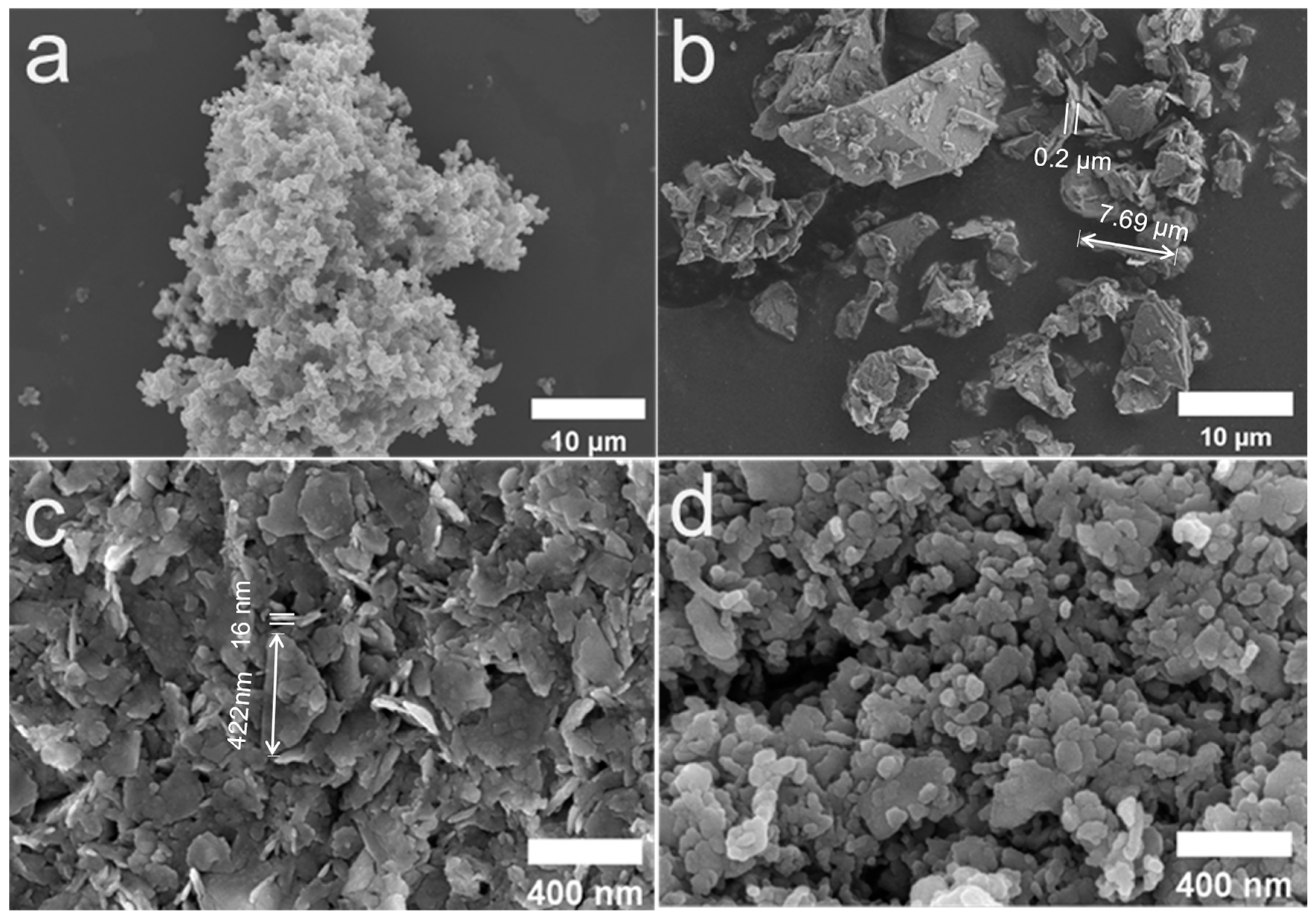
3.1. Microstructure Characterization of the MoS2 and the MoS2@PPy

SEM was used to characterize the microstructure of the PPy, the pristine MoS2, the MoS2 nanosheets, and after PPy modification. As can be seen in Figure 1a, Py was condensed into chains after chemical oxidation of ammonium persulfate in solution, forming a cotton cluster-like structure with the size of about 30 µm [24]. In Figure 1b, the original MoS2 was irregularly stacked, with a surface transverse dimension of 3–8 µm and a thickness of approximately 200–700 nm. After liquid-phase sonication in an ethanol/water solvent mixture, as shown in Figure 1c, the MoS2 became an irregular sheet with a size of 140–400 nm, and the thickness was between 5 and 16 nm, and the surface of the sample was flat and the edges were sharper. This phenomenon indicated that during the ultrasonic treatment, the block MoS2 was subjected to micro-jets and vibration waves generated by liquid vibration, overcame the van der Waals forces between the layers, and was broken into MoS2 nanosheets. Figure 1d showed that after the treatment of Py, the MoS2 nanosheets size did not change significantly, and the edges of the MoS2 nanosheets became rounded and the surface became rough. That is, MoS2 adsorbed a layer of substance on its surface. It showed that Py grows along the surface of MoS2 nanosheets [25]. As shown in Figure 2, during the exfoliation of MoS2, due to the generation of vacancy defects, MoS2 nanosheets were negatively charged and electrostatically adsorbed with Py+ cations oxidized by ammonium persulfate, Py+ then used MoS2 nanosheets as a template for directed chemical oxidative polymerization, and, finally, in situ oxidative polymerization to form MoS2@PPy composites.
The crystal structures of MoS2 and MoS2@PPy were characterized using UV–Vis spectroscopy and XRD. As can be seen in Figure 3a, the pristine MoS2 was a diagonal line without any obvious absorption peaks. After sonication, the MoS2 nanosheets showed UV absorption peaks at 618 nm and 672 nm [26], which were generated by direct electron leaps at the high symmetry point k in the Brillouin zone, which confirmed the successful exfoliative preparation of MoS2 nanosheets. A decrease in the number of layers of MoS2 also brings about an increase which affected its energy band gap, and in order to understand its energy band gap size, the Tuac diagram was further plotted by UV absorbance using the equation (αhν)1/m = b(hν − Eg), α = 2.303 × A/d, where the α is the absorption coefficient, the b is a constant, the h is Planck’s constant 4.135 × 10⁻¹⁵ eV·s, the ν is the UV frequency, the Eg denotes the semiconductor band gap, the d is the liquid layer thickness (0.01 m), the A is the absorbance, and the m of the indirect-gap semiconductor (MoS2) is 2 [27]. From the Tauc plot, the energy band gap of ultrasonically prepared MoS2 was at 1.57 eV, which was smaller than the monolayer MoS2 energy band gap (1.89 eV) and larger than the bulk MoS2 energy band gap (1.29 eV). The results also confirmed that the prepared MoS2 nanosheets were mainly of few-layer structure, and the work function of this few-layer structure MoS2 was generally at 4.5 eV, which was lower than the work function of Fe (4.73 eV), which was conducive to the generation of Schottky barriers (n-type barriers), resulting in effective protection against iron substrates [19].
The XRD plots depicted that the crystal structure of the original MoS2 was intact, and each diffraction peak was narrow and high, and tended to be a straight line. By comparison with the PDF of the crystal structure of MoS2, 14.46°, 29.14°, 32.81°, 33.61°, 36.03°, 39.69°, 44.35°, 49.93°, 56.07°, 58.38°, 60.24°, 70.29°, 72.84°, 76.12°, 77.49°, 80.22° corresponded to the crystallographic diffraction peaks of (002), (004), (100), (101), (102), (103), (006), (105), (106), (110), (008), (108), (203), (116), (0010), (205). It indicated a crystal structure type of 2H, a steady-state structure that exists in nature. Additionally, after ultrasonic treatment, each crystal plane was significantly reduced, which indicated that ultrasonic treatment did not change its crystal structure. At the same time, the (002) crystal plane was significantly reduced, which indicated that the MoS2 nanosheets were successfully exfoliated and had a few-layer structure, and the (002) diffraction peaks of MoS2@PPy became low and wide, probably because MoS2 was exfoliated to different degrees under the action of liquid-phase ultrasound, so that the diffraction peaks were strong at different positions in the (002) crystal plane. The haphazard diffraction peaks appeared at 17° to 28° diffraction peaks, which may be formed by the interference of PPy polymer chains [28]. Additionally, the (002) diffraction angles of MoS2 and MoS2@PPy were at 14.46° and 14.26°, respectively; this showed that the interlayer spacing of MoS2@PPy was increased, suggesting that the successful modification of PPy hindered the re-stacking of MoS2, confirming that the MoS2@PPy was prepared successfully.

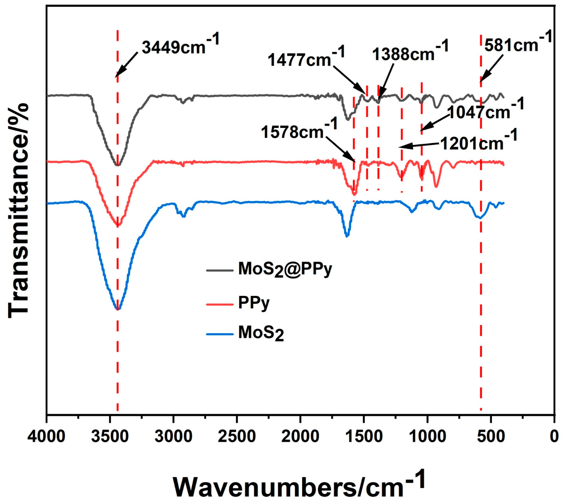
3.2. Chemical Structure and Composition of MoS2 and MoS2@PPy

The chemical composition of MoS2@PPy, PPy, and MoS2 with was characterized by FT-IR. From Figure 4, it can be seen that MoS2 with MoS2@PPy showed an absorption peak at 581 cm−1, which was related to the Mo–S vibration [29]. Additionally, in the MoS2 IR spectrum at 3449 cm−1, it may be generated the hydroxyl stretching vibration absorption [30], indicating that MoS2 changed from its original inert hydrophobic property to a certain hydrophilic property after ultrasound treatment. Regarding the PPy IR spectrum, the absorption peak at 1578 cm−1 was related to the C–C stretching vibration, while the absorption peaks at 1477 cm−1 and 1388 cm−1 were caused by the C–N symmetric stretching vibration and the C–N in-plane deformation vibration, and the peak observed at 1201 cm−1 was the breathing vibration peak of the pyrrole ring, the absorption peaks at 1047 cm−1 was the characteristic peak of C–H of pyrrole ring [31]. This demonstrated the successful chemical in situ polymerization of PPy on MoS2 nanosheets [32].

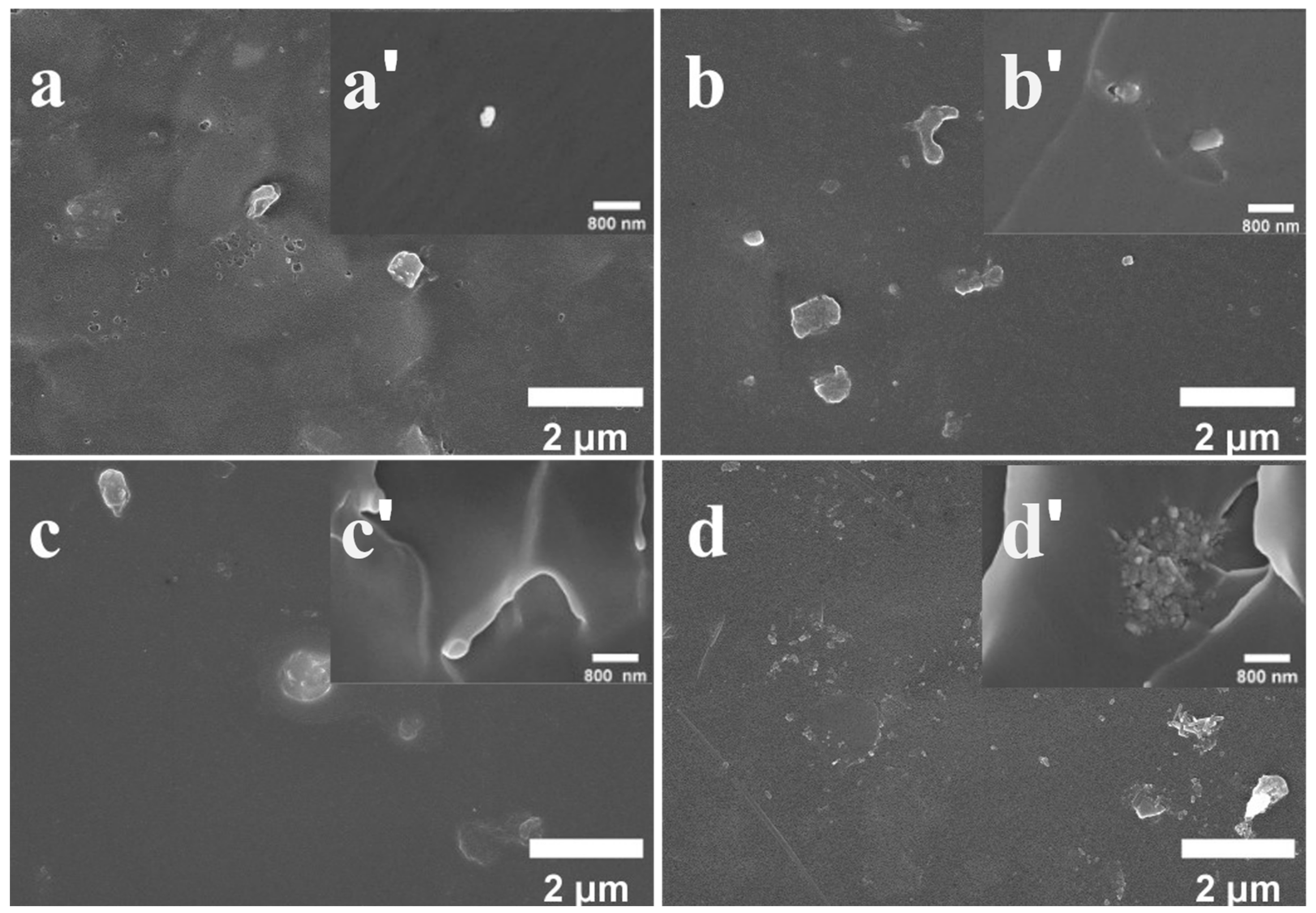
3.3. Surface Morphology of Different Composite Coatings

From Figure 5a, the surface of epoxy resin without added filler (MoS2) had a large number of micro-pores, which may be caused by solvent evaporation during the epoxy curing process. From Figure 5b, the surface of MoS2 coating with 0.4% added did not show obvious micro-pores, cracks, and other defects, which indicated that the addition of a certain amount of MoS2 flakes could well reduce the appearance of pores. However, in Figure 5b, it can be seen that the nano flakes showed some separation phenomenon with epoxy resin, indicating that the force between its interface and epoxy resin was poor [33]. From Figure 5c, it can be seen that after PPy modification, the surface of MoS2@PPy coating with 0.4% addition was smooth and the bump phenomenon on the surface was reduced, and the cross-section surface (Figure 5c) became rough from the brittle smooth cross-section surface of pure epoxy, indicating that MoS2@PPy effectively reduces the internal stress generated by the epoxy resin in the process of curing shrinkage volume, thus making the epoxy resin more dense and improving the corrosion resistance of the composite coating. From Figure 5d, with the increase in the addition of MoS2@PPy, flakes began to appear on the surface of the coating and were larger, but the phenomenon of protrusions was not obvious, and it can be seen in Figure 5d that the agglomeration phenomenon appeared at the crack gully [34]. This indicates that a certain amount of addition of MoS2@PPy is beneficial to reduce the generation of defects in the coating itself.

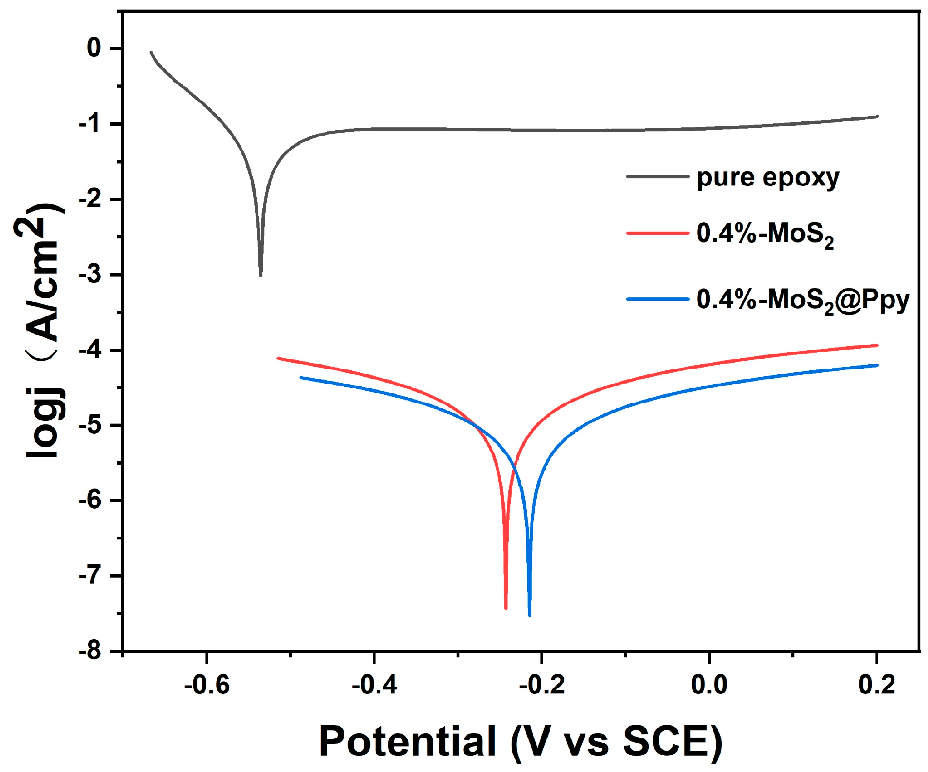
3.4. Polarization Curves for Different Coatings

Figure 6 shows the Tafel curves of epoxy resin, 0.4% added MoS2, and MoS2@PPy coating after 15 days of immersion at 3.5 wt.%, from which it can be seen that with the addition of nano MoS2, the corrosion potential of epoxy resin coating shifted to the right from −539.949 mV to −259.062 mV, and the corrosion current decreased from 19.134 µA to 0.049 µA, This indicated that the addition of nano MoS2 to the epoxy resin could effectively enhanced its corrosion resistance, while MoS2@PPy could further improve its corrosion resistance. As can be seen from Table 2, with the increase in the addition of MoS2 nanoflakes, the corrosion potential of MoS2 nanoflakes was the highest at 0.4% and the corrosion current was the lowest, and its corrosion ability decreased significantly with the further increase in the addition. As the addition of MoS2@PPy increased, the corrosion resistance was strongest around 0.8%, and the corrosion current decreased to 0.006 µA, which was four orders of magnitude lower than that of the pure epoxy coating, and the corrosion potential shifted right to −219.787 mV. By using the Stern–Geary equation and Faraday’s law, the polarization curve data were processed to obtain the polarization resistance (Rp) and annual corrosion rate, and the Rp of the coating increased significantly at 0–0.8% MoS2@PPy addition and the annual corrosion rate decreased, which further indicated that adding 0.8% MoS2@PPy to the epoxy resin coating was the best addition. The comparison of corrosion current and corrosion potential of the KH560 modified MoS2 nanosheet epoxy coating prepared by the previous authors showed that PPy can effectively improve the corrosion resistance of MoS2 in epoxy resin. This may be due to the poor compatibility of MoS2 nanoflakes with epoxy resin as observed by SEM of the previous coating, and the increase in the addition led to its agglomeration, thus reducing its anti-corrosion properties, The PPy-modified MoS2 nanosheets were more compatible with epoxy resin, reducing its agglomeration phenomenon in epoxy resin, thus substantially improving the anti-corrosion ability of its composite coating.

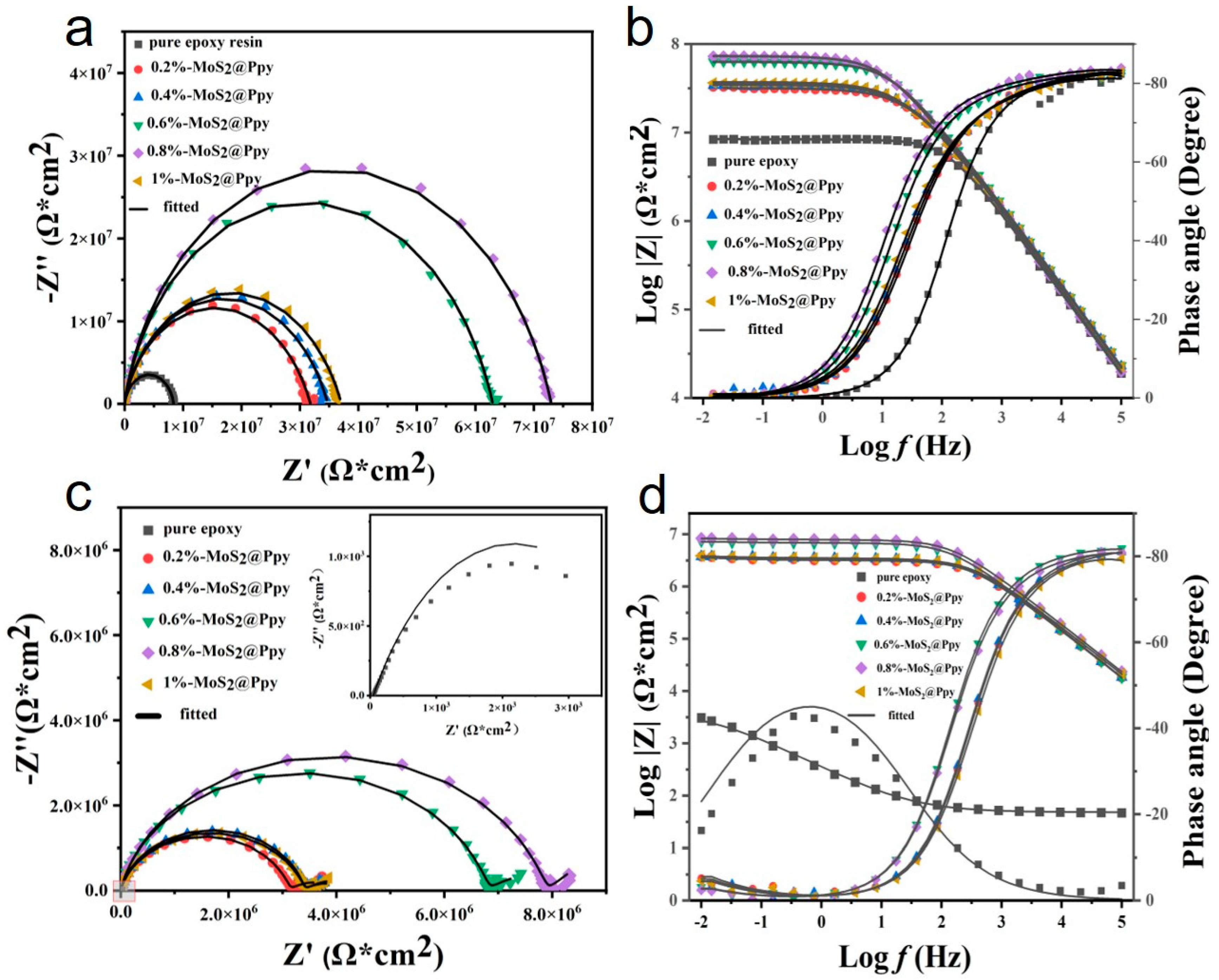
3.5. Electrochemical Impedance Test

By using EIS to test the MoS2@PPy organic coating after different immersion times in 3.5 wt.% NaCl solution and using equivalent circuit fitting, the results are shown in Figure 7, with the coating in NaCl solution continuously soaked, the radius of the capacitive arc of the coating in the Nyquist diagram (Figure 7a,c) was continuously reduced with the soaking time, and the size of the radius of the capacitive were reflects the strength of the coating corrosion resistance, as can be seen in Figure 7d. With the continuation of the soaking time to 360 h, the radius of the pure epoxy resin coating in the low frequency region was reduced from 8.35 × 10⁶ Ω·cm2 down to 3.07 × 10³ Ω·cm2, the anticorrosive ability was substantially reduced, while after adding into MoS2@PPy, the composite coating was reduced from about 1 × 10⁷ Ω·cm2 to about 1 × 10⁶ Ω·cm2, which was probably because MoS2@PPy played a physical barrier role in the epoxy resin coating, which greatly improved the charge transfer resistance of the epoxy coating. This was conducive to the protection of the coating against the metal base. The epoxy coating with 0.8% MoS2@PPy added had the largest capacitance arc, which indicates that it had the strongest protection against the metal base, while the epoxy coating with 1% MoS2@PPy added was relatively substantially reduced, which may be due to the serious agglomeration of MoS2@PPy in the coating, thus reducing the resistance of the coating. To further understand the coating corrosion condition, Figure 7a shows a semicircular arc, while in Figure 7b, it can be seen in the phase angle versus frequency curve that a peak appeared, which indicates that each coating had only one time constant, indicating that the coating was in the early stage of immersion. As seen in Figure 7c, MoS2@PPy coating after 360 h of immersion, the slope of about 0.3 appeared in the low-frequency region, indicating that the corrosive medium began to infiltrate and enter the middle stage of corrosion of the composite coating, the metal substrate began to be corroded [36,37], but MoS2@PPy remained above 1 × 10⁶ Ω·cm2 without significant changes, confirming that the composite coating still blocked the corrosive medium to metal substrate. As seen in Figure 7d, the phase angle versus frequency curve can be clearly seen in two time constants, and each coating after a long period of immersion, the epoxy corrosion process entered the late stage, while the coating resistance of pure epoxy coating was reduced to about 3078.9 Ω·cm2 and lost its anticorrosive ability. This indicates that the addition of MoS2@PPy can effectively enhance the corrosion protection of epoxy resin on carbon steel. Figure 8 shows the corresponding equivalent circuit: Rs was the solution resistance, CPEc was the coating capacitance, Rc was the coating resistance, Rct was the coating-metal interface electron transfer resistance, CPEdl was the coated-metal interface electric double-layer capacitance, and W was the Warburg impedance [38]. After fitting the data, it can be seen from Table 3 and Table 4 that the coating resistance Rc decreases with the increase of immersion time, while the coating impedance CPEc begins to gradually increase, indicating that the corrosive medium begins to penetrate into the coating. Rct of the coating-metal interface of MoS2@PPy was significantly higher than that of the epoxy coating, indicating that the protection of MoS2@PPy in the late stages of corrosion mainly plays a role in passivating the metal interface and inhibiting the transfer of electrons from the metal matrix by the corrosive medium, thus delaying the occurrence of metal corrosion.

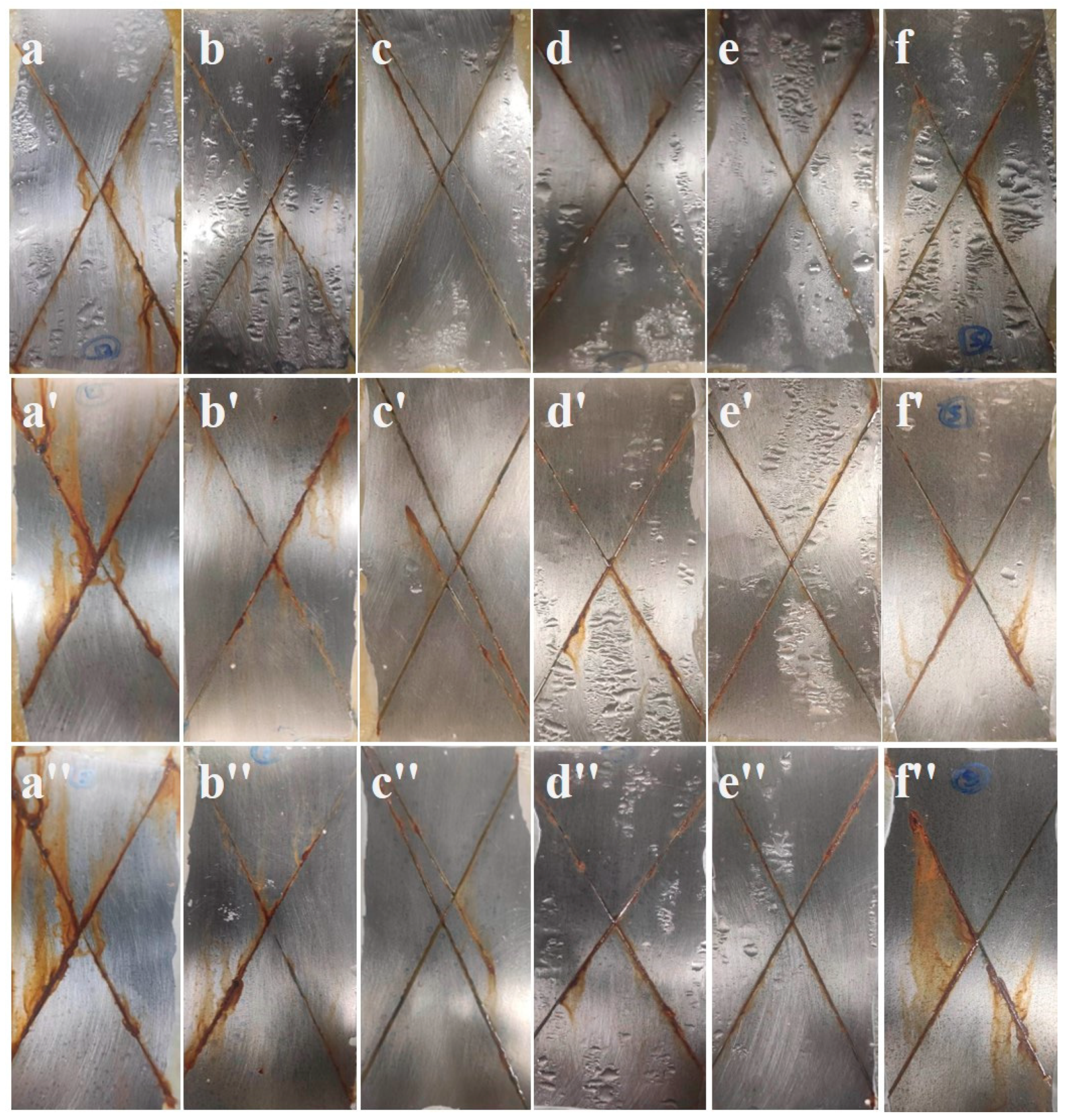
3.6. Salt Spray Test

In order to understand the corrosion resistance of MoS2@PPy epoxy composite coating, a 30 d scratch salt spray test was conducted (Figure 9). It can be seen that after 10 d of salt spray corrosion, the pure epoxy coating showed rust stains and started to extend on the coating surface, the corrosion condition of MoS2@PPy epoxy coating was slightly reduced at 0–0.8% addition, a small amount of rust stains appeared in the seam of 0.8% sample, and 1% addition started to appeared more serious corrosion. When the salt spray corrosion test started to 30 d later, the corrosion of pure epoxy resin became more and more serious, and the corrosion products increased a lot and formed a loose rust layer, while the MoS2@PPy epoxy coating appeared rust in the samples with 0–0.8% addition, but the rust layer was mainly concentrated at the scratches and hindered the continuous corrosion of the salt spray on the scratches, but the addition of 1% appeared a lot of corrosion products and the rust layer was loose. However, the rust layer was loose and fell off with the salt spray, of which the best corrosion performance was 0.8% and the rust was not obvious, indicating that the addition of a certain amount of MoS2@PPy was beneficial to the corrosion resistance of the epoxy coating, and the best amount of MoS2@PPy was 0.8%.

3.7. Anti-Corrosion Mechanism

According to the previous data, the addition of MoS2@PPy, MoS2 can effectively improve the corrosion resistance of the epoxy coating, and the presumed anti-corrosion mechanism is shown in Figure 10, which shows that the coating film formation process will produce various defects (micro-cracks, micro-pores), and in the early stage of immersion, MoS2@PPy, MoS2 mainly plays a physical barrier role, which inhibits the appearance and expansion of cracks, thus preventing the intrusion of corrosive media (Cl, O2). When reaching the middle of soaking, the corrosive medium starts to contact the surface of the metal substrate, MoS2 no longer has an anticorrosive effect, but MoS2@PPy remains starts to play the role of metal passivation, inhibiting the emergence and spread of the corrosion process, thus extending the protection time of the epoxy coating on the metal substrate.

4. Conclusions

In this paper, MoS2@PPy anticorrosive epoxy coatings were prepared in a simple way, and no organic solvents were used in the preparation process, which is friendly to the environment. The dispersion of PPy in the epoxy resin was improved and the densities of the composites were increased by ultrasonic treatment of the body material MoS2 with PPy. It was shown by experiments that the corrosion potential of the composite coating with 0.8% filler MoS2@PPy was increased from −539.949 mV to −219.787 mV relative to the epoxy coating, the annual corrosion rate of the composite coating with 0.8% filler MoS2@PPy was decreased from 0.144 mm/year to 9.92 × 10⁻⁶ mm/year relative to the epoxy coating, and the corrosion current density was reduced by about four orders of magnitude, effectively improving the corrosion resistance of the epoxy resin. After 30 days of constant temperature and humidity salt spray scratch test, it was shown that the MoS2@PPy composite coating can protect carbon steel for a long time. For the corrosion protection mechanism, due to objective conditions, we did not perform a crystal structure analysis of the protected metal matrix and corrosion products in order to better study and elaborate the experimental findings. It is hoped that this work will provide ideas for the application of MoS2 in corrosion protection.

Author Contributions

Conceptualization, Y.Z.; Methodology, Y.Z.; Validation, F.L., H.L. and K.Z.; Formal analysis, J.D., F.L. and H.L.; Investigation, J.D.; Resources, X.Y.; Writing—original draft, Y.Z.; Writing—review & editing, J.T.; Project administration, X.Y.; Funding acquisition, K.Z. All authors have read and agreed to the published version of the manuscript.

Funding

This research was financially supported by the Comprehensive Development Project of Marine Ecological Materials in South China Sea (No. HT-KYH-2018199) and Research and Development of New Waterproof Sealing Material for Prefabricated Building and its Industrial Application (No. 2022-006). Meanwhile, this research sincerely thanks Hainan Blue Island Environmental Protection Industry Co., Ltd. for providing convenience in the use and performance test of the equipment.

Institutional Review Board Statement

Not applicable.

Informed Consent Statement

Not applicable.

Data Availability Statement

Data openly available in a public repository.

Conflicts of Interest

The authors declare no conflict of interest.

References

  1. Morin, J.; Brochard, G.; Bergé, V.; Rosset, A.; Artous, S.; Clavaguera, S.; Strekowski, R.S.; Wortham, H. Uptake of m-xylene and VOC emissions by mineral photocatalytic paints of indoor air building interest. Environ. Sci. Nano 2023, in press. [CrossRef]
  2. Massou, M.; Babu, N.; Xian, G. Experimental study on the mechanical properties of CFRP/epoxy composite plates under seawater immersion. Structures 2023, 54, 48–57. [Google Scholar] [CrossRef]
  3. Zhao, Q.; Lu, Z.; Wu, Y.; Zhao, W. Designing strong interfacial adhesion between carbon fiber and epoxy resin via dopamine towards excellent protection ability under high hydrostatic pressure and severe erosion corrosion condition. Compos. Sci. Technol. 2022, 217, 109090. [Google Scholar] [CrossRef]
  4. Huang, H.; Sheng, X.; Tian, Y.; Zhang, L.; Chen, Y.; Zhang, X. Two-Dimensional Nanomaterials for Anticorrosive Polymeric Coatings: A Review. Ind. Eng. Chem. Res. 2020, 59, 15424–15446. [Google Scholar] [CrossRef]
  5. Li, H.; Zhang, Q.-H.; Meng, X.-Z.; Liu, P.; Wu, L.-K.; Cao, F.-H. A novel cerium organic network modified graphene oxide prepared multifunctional waterborne epoxy-based coating with excellent mechanical and passive/active anti-corrosion properties. Chem. Eng. J. 2023, 465, 142997. [Google Scholar] [CrossRef]
  6. Aleithan, S.H.; Al-Amer, K.; Alabbad, Z.H.; Khalaf, M.M.; Alam, K.; Alhashem, Z.; Abd El-Lateef, H.M. Highly scalable synthesis of MoS2 thin films for carbon steel coatings: Influence of synthetic route on the nanostructure and corrosion performance. J. Mater. Res. Technol. 2023, 23, 1239–1251. [Google Scholar] [CrossRef]
  7. Wu, J.; Wang, H.; Li, R.; Guo, L. Anticorrosive waterborne polyurethane coating with Gemini surfactant-assisted exfoliation of hexagonal boron nitride nanosheets. J. Appl. Polym. Sci. 2023, e54008. [Google Scholar] [CrossRef]
  8. Xing, X.; Sui, Y.; Li, Q.; Yuan, M.; Zhao, H.; Zhou, D.; Chu, X.; Liu, S.; Tang, E. Multifunctional ZnAl-MoO4 LDH assembled Ti3C2Tx MXene composite for active/passive corrosion protection behavior of epoxy coatings. Appl. Surf. Sci. 2023, 623, 157092. [Google Scholar] [CrossRef]
  9. Bai, Z.; Meng, S.; Cui, Y.; Sun, Y.; Pei, L.; Hu, H.; Jiang, Y.; Wang, H. A stable anticorrosion coating with multifunctional linkage against seawater corrosion. Compos. Part B Eng. 2023, 259, 110733. [Google Scholar] [CrossRef]
  10. Dong, M.; Zhang, H.; Tzounis, L.; Santagiuliana, G.; Bilotti, E.; Papageorgiou, D.G. Multifunctional epoxy nanocomposites reinforced by two-dimensional materials: A review. Carbon 2021, 185, 57–81. [Google Scholar] [CrossRef]
  11. Quezada-Renteria, J.A.; Chazaro-Ruiz, L.F.; Rangel-Mendez, J.R. Poorly conductive electrochemically reduced graphene oxide films modified with alkyne chains to avoid the corrosion-promoting effect of graphene-based materials on carbon steel. Carbon 2020, 167, 512–522. [Google Scholar] [CrossRef]
  12. Schriver, M.; Regan, W.; Gannett, W.J.; Zaniewski, A.M.; Crommie, M.F.; Zettl, A. Graphene as a Long-Term Metal Oxidation Barrier: Worse Than Nothing. ACS Nano 2013, 7, 5763–5768. [Google Scholar] [CrossRef] [PubMed]
  13. Kumari, S.; Chouhan, A.; Sharma, O.P.; Kuriakose, S.; Tawfik, S.A.; Spencer, M.J.S.; Walia, S.; Sugimura, H.; Khatri, O.P. Structural-Defect-Mediated Grafting of Alkylamine on Few-Layer MoS2 and Its Potential for Enhancement of Tribological Properties. ACS Appl. Mater. Interfaces 2020, 12, 30720–30730. [Google Scholar] [CrossRef] [PubMed]
  14. Li, Z.; Hu, J.; Li, Y.; Liu, J. Polyaniline/zinc/cerium nitrate pigment for epoxy based anticorrosion coatings. React. Funct. Polym. 2018, 131, 22–28. [Google Scholar] [CrossRef]
  15. Meng, R.; Liu, L.; Guo, W. Mussel-inspired polydopamine and Al2O3 nanoparticles co-modified MoS2 for reinforcing anticorrosion of epoxy coatings. Colloid Polym. Sci. 2023, 301, 175–187. [Google Scholar] [CrossRef]
  16. Vandana, S.; Kochat, V.; Lee, J.; Varshney, V.; Yazdi, S.; Shen, J.; Kosolwattana, S.; Vinod, S.; Vajtai, R.; Roy, A.K.; et al. 2D Heterostructure coatings ofhBN-MoS2layers for corrosion resistance. J. Phys. D Appl. Phys. 2017, 50, 045301. [Google Scholar] [CrossRef]
  17. Xia, Z.; Liu, G.; Dong, Y.; Zhang, Y. Anticorrosive epoxy coatings based on polydopamine modified molybdenum disulfide. Prog. Org. Coat. 2019, 133, 154–160. [Google Scholar] [CrossRef]
  18. Xia, Y.; He, Y.; Chen, C.; Wu, Y.; Chen, J. MoS2 nanosheets modified SiO2 to enhance the anticorrosive and mechanical performance of epoxy coating. Prog. Org. Coat. 2019, 132, 316–327. [Google Scholar] [CrossRef]
  19. Ding, J.H.; Zhao, H.R.; Zhao, X.P.; Xu, B.Y.; Yu, H.B. How semiconductor transition metal dichalcogenides replaced graphene for enhancing anticorrosion. J. Mater. Chem. A 2019, 7, 13511–13521. [Google Scholar] [CrossRef]
  20. Tang, H.; Wang, J.; Yin, H.; Zhao, H.; Wang, D.; Tang, Z. Growth of polypyrrole ultrathin films on MoS2 monolayers as high-performance supercapacitor electrodes. Adv. Mater. 2015, 27, 1117–1123. [Google Scholar] [CrossRef]
  21. Lu, F.; Liu, C.; Chen, Z.; Veerabagu, U.; Chen, Z.; Liu, M.; Hu, L.; Xia, H.; Cha, L.; Zhang, W. Polypyrrole-functionalized boron nitride nanosheets for high-performance anti-corrosion composite coating. Surf. Coat. Technol. 2021, 420, 127273. [Google Scholar] [CrossRef]
  22. Halim, U.; Zheng, C.R.; Chen, Y.; Lin, Z.; Jiang, S.; Cheng, R.; Huang, Y.; Duan, X. A rational design of cosolvent exfoliation of layered materials by directly probing liquid-solid interaction. Nat. Commun. 2013, 4, 2213. [Google Scholar] [CrossRef] [PubMed] [Green Version]
  23. Jing, Y.; Wang, P.; Yang, Q.; Wang, Q.; Bai, Y. MoS2 decorated with ZrO2 nanoparticles through mussel-inspired chemistry of dopamine for reinforcing anticorrosion of epoxy coatings. Colloids Surf. A Physicochem. Eng. Asp. 2021, 608, 125625. [Google Scholar] [CrossRef]
  24. He, Z.; Lin, H.; Zhang, X.; Chen, Y.; Bai, W.; Lin, Y.; Jian, R.; Xu, Y. Self-healing epoxy composite coating based on polypyrrole@MOF nanoparticles for the long-efficiency corrosion protection on steels. Colloids Surf. A Physicochem. Eng. Asp. 2023, 657, 130601. [Google Scholar] [CrossRef]
  25. Xiang, L.; Niu, C.-G.; Tang, N.; Lv, X.-X.; Guo, H.; Li, Z.-W.; Liu, H.-Y.; Lin, L.-S.; Yang, Y.-Y.; Liang, C. Polypyrrole coated molybdenum disulfide composites as adsorbent for enhanced removal of Cr(VI) in aqueous solutions by adsorption combined with reduction. Chem. Eng. J. 2021, 408, 127281. [Google Scholar] [CrossRef]
  26. Yin, X.; Li, Y.; Meng, H.; Wu, W. Surface functionalization of bulk MoS2 sheets for efficient liquid phase exfoliation in polar micromolecular solvents. Appl. Surf. Sci. 2019, 486, 362–370. [Google Scholar] [CrossRef]
  27. Mak, K.F.; Lee, C.; Hone, J.; Shan, J.; Heinz, T.F. Atomically thin MoS2: A new direct-gap semiconductor. Phys. Rev. Lett. 2010, 105, 136805. [Google Scholar] [CrossRef] [Green Version]
  28. Su, Q.; Wang, B.; Mu, C.; Zhai, K.; Nie, A.; Xiang, J.; Wen, F. Polypyrrole coated 3D flower MoS2 composites with tunable impedance for excellent microwave absorption performance. J. Alloys Compd. 2021, 888, 161487. [Google Scholar] [CrossRef]
  29. Yang, J.; Ye, M.; Han, A.; Zhang, Y.; Zhang, K. Preparation and electromagnetic attenuation properties of MoS2–PANI composites: A promising broadband absorbing material. J. Mater. Sci. Mater. Electron. 2019, 30, 292–301. [Google Scholar] [CrossRef]
  30. Chen, C.; He, Y.; Xiao, G.; Xia, Y.; Li, H.; He, Z. Two-dimensional hybrid materials: MoS2-RGO nanocomposites enhanced the barrier properties of epoxy coating. Appl. Surf. Sci. 2018, 444, 511–521. [Google Scholar] [CrossRef]
  31. Omastová, M.; Trchová, M.; Pionteck, J.; Prokeš, J.; Stejskal, J. Effect of polymerization conditions on the properties of polypyrrole prepared in the presence of sodium bis(2-ethylhexyl) sulfosuccinate. Synth. Met. 2004, 143, 153–161. [Google Scholar] [CrossRef]
  32. Wang, T.; Liu, W.; Tian, J.; Shao, X.; Sun, D. Structure characterization and conductive performance of polypyrrol-molybdenum disulfide intercalation materials. Polym. Compos. 2004, 25, 111–117. [Google Scholar] [CrossRef]
  33. Obaid, A.N.; Al-Bermany, E. Performance of functionalized graphene oxide to improve anti-corrosion of epoxy coating on 2024-T3 aluminium alloy. Mater. Chem. Phys. 2023, 305, 127849. [Google Scholar] [CrossRef]
  34. Wu, Y.; He, Y.; Chen, C.; Li, H.; Xia, Y.; Zhou, T. MoS2-CNFs composites to enhance the anticorrosive and mechanical performance of epoxy coating. Prog. Org. Coat. 2019, 129, 178–186. [Google Scholar] [CrossRef]
  35. Jing, Y.; Wang, P.; Yang, Q.; He, Y.; Bai, Y. The effect of a functionalized defect-rich molybdenum disulfide nanosheets on anticorrosion performance of epoxy coating. Mater. Res. Express 2019, 6, 086473. [Google Scholar] [CrossRef]
  36. Zhou, S.; Wu, Y.; Zhao, W.; Yu, J.; Jiang, F.; Ma, L. Comparative corrosion resistance of graphene sheets with different structures in waterborne epoxy coatings. Colloids Surf. A Physicochem. Eng. Asp. 2018, 556, 273–283. [Google Scholar] [CrossRef]
  37. Liu, S.; Wang, X.; Yin, Q.; Xiang, X.; Fu, X.-Z.; Wang, X.-Z.; Luo, J.-L. A facile approach to fabricating graphene/waterborne epoxy coatings with dual functionalities of barrier and corrosion inhibitor. J. Mater. Sci. Technol. 2022, 112, 263–276. [Google Scholar] [CrossRef]
  38. Xing, C.; Wang, W.; Qu, S.; Tang, Y.; Zhao, X.; Zuo, Y. Degradation of zinc-rich epoxy coating in 3.5% NaCl solution and evolution of its EIS parameters. J. Coat. Technol. Res. 2021, 18, 843–860. [Google Scholar] [CrossRef]
Figure 1. SEM images of (a) polypyrrole (PPy), (b) pristine molybdenum disulfide (MoS2), (c) MoS2 nanosheets and (d) Polypyrrole-coated molybdenum disulfide (MoS2@PPy).
Coatings 13 01046 g001
Figure 2. Flowchart of synthesis and preparation of polypyrrole-coated molybdenum disulfide (MoS2@PPy).
Coatings 13 01046 g002
Figure 3. (a) UV–vis spectrum of pristine molybdenum disulfide (MoS2), MoS2 nanosheets; (b) XRD pattern of pristine MoS2 and Polypyrrole-coated molybdenum disulfide (MoS2@PPy).
Coatings 13 01046 g003
Figure 4. FT-IR spectra of polypyrrole-coated molybdenum disulfide (MoS2@PPy), polypyrrole (PPy), and molybdenum disulfide nanosheets (MoS2).
Coatings 13 01046 g004
Figure 5. SEM of different coating surfaces, (a) pure epoxy coating, (b) contains 0.4% molybdenum disulfide epoxy coating, (c) contains 0.4% polypyrrole-coated molybdenum disulfide epoxy coating, (d) contains 0.8% polypyrrole-coated molybdenum disulfide epoxy coating; (a′d′) represent SEM images from liquid nitrogen cross-section.
Coatings 13 01046 g005
Figure 6. Tafel curves of coatings soaked in 3.5 wt.% NaCl for 15 d; contains 0.4% molybdenum disulfide epoxy coating (0.4% MoS2), contains 0.4% polypyrrole-coated molybdenum disulfide epoxy coating (0.4% MoS2@PPy).
Coatings 13 01046 g006
Figure 7. Nyquist plot on the left and bode plot on the right (a,b) for immersion time of 24 h; (c,d) for immersion time of 360 h.
Coatings 13 01046 g007
Figure 8. (a) The equivalent circuit diagram in the initial of immersion (Rs, the solution resistance; CPEc, the coating capacitance; Rc, the coating resistance), (b) the equivalent circuit diagram with the appearance of Warburg impedance. (Rs, the solution resistance; CPEc, the coating capacitance; Rc, the coating resistance; W, the Warburg impedance; Rct, the coating-metal interface electron transfer resistance; CPEdl, the coated-metal interface electric double-layer capacitance).
Coatings 13 01046 g008
Figure 9. Neutral salt spray resistance test diagram. (af) MoS2@PPy additive amount of 0%, 0.2%, 0.4%, 0.6%, 0.8%, 1% epoxy coating in 5 wt.% NaCl neutral salt spray test after sample, (a′f′) the corresponding sample after the corrosion of neutral salt spray to 20 d. (a″f″) the corresponding sample after the corrosion of neutral salt spray to 30 d.
Coatings 13 01046 g009
Figure 10. The anti-corrosion mechanism diagram.
Coatings 13 01046 g010
Table 1. Content of components of the composite EP coatings (E51, epoxy resin; D230, polyamide; Fillers, molybdenum disulfide or polypyrrole-coated molybdenum disulfide).
SamplesContent Ratio
Components00.2%0.4%0.6%0.8%1%
Composite EP coatingE51 (g)101010101010
D230 (g)3.23.23.23.23.23.2
Fillers (g)00.030.050.080.110.13
Table 2. The corrosion potential (Ecorr), corrosion current (Icorr), corrosion rate and polarization resistance (Rp) of composite coating immersed in 15 days.
SamplesContent Ratio
00.2%0.4%0.6%0.8%1%
MoS2@PPyEcorr (mV)−539.949−238.370−243.606−223.766−219.787−249.52
Icorr (µA/cm2)19.1340.0140.0130.0070.0060.013
Rp (Ω)5943.51 × 1063.73 × 1067.14 × 1067.95 × 1063.67 × 106
Corrosion rate (mm/year)0.1442.34 × 10−51.51 × 10−41.05 × 10−59.92 × 10−62.33 × 10−5
MoS2Ecorr (mV)−539.949−422.035−259.062−575.780−524.501−251.553
Icorr (µA/cm2)19.1340.0700.04912.9009.8390.054
KH560–MoS2 [35]Ecorr (mV)−490.1−437.1−456.8−417.6−445.2−466.7
Icorr (µA/cm2)0.22390.15490.16220.15340.14130.1445
Table 3. The electrochemical parameters of MoS2@PPy epoxy coatings for 1 d immersion time.
SamplesContent Ratio
00.2%0.4%0.6%0.8%1%
1 d
MoS2@PPy
Rs (Ω·cm2)4.76 × 1035.09 × 1035.42 × 1035.67 × 1034.10 × 1035.50 × 103
Rc (Ω·cm2)8.80 × 1062.97 × 1073.17 × 1075.95 × 1076.89 × 1073.36 × 107
CPEc
−1·cm−2·sn)
1.08 × 10−109.57 × 10−119.42 × 10−119.41 × 10−111.10 × 10−119.64 × 10⁻¹¹
Table 4. The electrochemical parameters of MoS2@PPy epoxy coatings for 15 d immersion time.
SamplesContent Ratio
00.2%0.4%0.6%0.8%1%
15 d
MoS2@PPy
Rs (Ω·cm2)0.53 × 1033.36 × 1034.81 × 1032.43 × 1034.78 × 1034.69 × 103
Rc (Ω·cm2)146.67.66 × 1053.32 × 1061.45 × 1061.58 × 1069.75 × 105
CPEc
−1·cm−2·sn)
1.01 × 10−41.00 × 10−101.10 × 10−109.91 × 10−117.79 × 10−118.64 × 10⁻¹¹
W (Ω·cm2)2.15 × 10−35.43 × 10−65.86 × 10−64.29 × 10−61.94 × 10−65.81 × 10−6
CPEdl
−1·cm−2·sn)
5.72 × 10−41.19 × 10−102.26 × 10−81.08 × 10−109.09 × 10−111.23 × 10⁻¹⁰
Rct (Ω·cm2)1.04 × 1032.32 × 1061.51 × 1055.16 × 1065.89 × 1062.36 × 106
Disclaimer/Publisher’s Note: The statements, opinions and data contained in all publications are solely those of the individual author(s) and contributor(s) and not of MDPI and/or the editor(s). MDPI and/or the editor(s) disclaim responsibility for any injury to people or property resulting from any ideas, methods, instructions or products referred to in the content.

