Abstract
In the present work, the titanium carbonitride coatings were deposited by the reactive magnetron sputtering method at different substrate bias: 0, −70 V, and −100 V. The effect of the substrate bias on the structure, composition, and mechanical and tribological properties of titanium carbonitride coatings was studied. Scanning electron microscopy, nanoindentation, sliding wear test (ball-on-disk method), X-ray phase, and elemental analysis methods were used to evaluate the tribological properties and microstructure of the thin coatings. The dependencies obtained resulted in the determination of the most preferred mode of deposition by magnetron sputtering at a negative substrate bias in an atmosphere of argon–acetylene–nitrogen.
1. Introduction
Hard protective coatings greatly contribute to the increase in wear resistance and corrosion resistance of metals/metal alloys [1,2,3]. Currently, the titanium carbonitride (TiCN) is of high relevance to create wear-resistant protective coatings with the purpose of ensuring the maximum wear resistance and service life of friction unit parts. TiCN is a more suitable coating for parts operating in constant friction due to its high resistance to abrasion and wear [4,5]. TiCN coatings are formed by mixing C and N in an FCC (face-centered cubic) structure and appear to have the best properties of the two original components, such as the plasticity of TiC and adhesion strength of TiN. It was found that the tribological properties of TiCN depend on the substrate, the deposition method, film thickness, and structure features [6]. Therefore, it is of great technological importance to develop effective methods of TiCN coatings production under real industrial conditions.
Various physical and chemical deposition techniques are used today to produce TiCN coatings. There are methods such as magnetron sputtering (MS) [7,8,9], cathode sputtering [10], plasma deposition [11], laser methods [12,13], CVD-based methods [14,15], hybrid deposition [16,17], and others. MS is one of the promising methods for the deposition of TiCN coatings with increased wear resistance. MS has a low level of impurities and allows easy contro l of the deposition rate [18]. This method also produces coatings with different morphologies and crystallographic structures depending on the sputtering conditions. TiCN coatings exhibit a wide range of different properties depending on the magnetron sputtering conditions such as reactive gas pressure and composition, operating pressure, temperature, material and composition of the target, substrate, and others. Several studies of TiCN [8,19,20,21,22] have been performed to study the effect of sputtering conditions on the properties of TiCN coatings, and the effect of substrate bias has not been clarified sufficiently. It is of interest in this connection to study the effect of the substrate bias on TiCN films obtained by reactive MS.
2. Materials and Methods
Titanium carbonitride (TiCN) coatings were deposited in a direct current MS system using a 99 mm diameter, 5 mm thick titanium target of the VT1–0 grade. The distance between the target and the substrate holder was kept constant at 30 cm. Well-polished plates (15 mm × 15 mm) and disks (Ø58 mm) made of VT6 titanium were used as substrates. The substrate surface was preliminarily prepared for cleaning from various contaminants, which included grinding, polishing, acetone cleaning, and ion cleaning in vacuum. First, grinding was carried out with abrasive papers P120, P180, P320, P600, P1200, and P2000. Then, a three-stage polishing with diamond paste was performed: 5/1 (3–5 μm), 2/1 (1–2 μm), 1/0 (1 μm). After polishing, the substrates were washed with distilled water for 10 min and degreased with acetone. After performing the above processes, the substrates were placed in the working chamber. The chamber was pumped down to the base pressure below 5–10−3 Pa before deposition. The MS unit is equipped with an APEL-IS-21CELL ion source (Applied Electronics, Tomsk, Russia) and APELMRE 100 magnetrons (Applied Electronics, Tomsk, Russia). The substrates were ion-cleaned with argon at an operating voltage of 2.5 kV, a current of 20–25 mA, a pressure of 0.2 Pa, and a duration of 20 min before coating deposition. Testing of TiCN coating deposition modes was performed under the conditions of asymmetric power supply to the magnetron sputtering system. The substrate bias for this purpose was applied not only to the magnetron but also to the substrate. The substrate bias e (Us) was 0, −70, and −100 V, which was supplied by an APEL-M-5PDC power supply (Applied Electronics, Tomsk, Russia). The flow of inert and reaction gas was controlled by RRG-12 Model flow meters (Eltochpribor, Moscow, Russia). The flow for Ar was set at 18 sccm, for C2H2, it was set at 4.6 sccm, and for N2, it was set at 2.6 sccm. The total flow of Ar/C2H2+N2 gas was set to 25.2 sccm to keep the working pressure in the chamber at 0.4 Pa. Plasma was ignited after the Ar/C2H2+N2 gas atmospheric working pressure was reached. The plasma current was fixed in all experiments at 2 A, the voltage varied in the range of 500–700 V. The deposition time of all coatings was constant, 2 h. Finally, the thickness of TiCN films was about 1–1.5 µm.
TiCN films were analyzed for morphology, elemental and phase composition, tribologic tests, and nanohardness. The deposition rate (DR) was defined as the ratio of coating thickness to deposition time. The thickness of the coatings was measured by the weight method by weighing 36 cm2 aluminum foil before and after deposition using a Sartorius Cubis MSA3.6P (Sartorius, Goettingen, Germany) analytical scale with an accuracy of 1 µg and checked by scanning electron microscopy (SEM) (JEOL, Tokyo, Japan).
The morphology of the coatings was analyzed by SEM on a JXA-8230 microscope (JEOL, Tokyo, Japan) at an accelerating voltage of 25 kV and an electron beam current of up to 7 nA. The backscattered electron mode (СОМРО) was used for all sample sections selected for SEM study. The elemental composition of the coating was determined by energy-dispersive X-ray analysis (EDX). To check the coating thickness, the coating was deposited on glass. Then, for examination, a thin plate of another glass was compressed onto the surface of the already coated glass sample on a special holder. Thus, using the SEM image, it was possible to check the thickness of the coating in several areas.
The phase composition of the coating was determined by a D8 Advance diffractometer (BRUKER, Karlsruhe, Germany) with radiation α-Cu (λ ≈ 1.54 Å). X-ray photography was performed with focusing according to the Bragg–Brentano method. Diffraction patterns were recorded in the range of angles 2θ: 20 ÷ 90° with a step of 0.05°, and the shooting speed was 2 deg/min at a voltage of 35 kV and a current of 20 mA. The PDF 2 database was used for the phase analysis.
The tribological characteristics of the coatings were measured in the sliding friction mode according to the “ball-on-disk” scheme on a TRB3 tribometer (CSM Instruments, Peseux, Switzerland). Sample rotation speed, 1 cm/s; load, 1 N; wear track radius, 7 mm; friction path, 100 m; data collection speed: 50 Hz, a Si3N4 ball with a diameter of 6 mm was used as a counter body. The reduced wear was calculated using the volumetric wear of the coatings during the tribological test. To do this, using profilometry, the cross-sectional area of the wear track was measured.
Nanoindentation was performed on a NanoScan-4D nano-hardness tester (Nanoscan, Moscow, Russia). We made 10 indentations with a Berkovich indenter at a load of 50 mN. The indenter penetration depth into the coating was 340–400 nm. Young’s modulus and hardness were determined by the method of Oliver and Farr.
3. Results and Discussion
Figure 1 shows the dependence of the deposition rate and thickness of the TiCN coating on the negative substrate bias. The thickness of the TiCN coating as can be seen from the graph (Figure 1, black line) on the substrate without voltage is 1.45 μm; further, it decreases to 0.87 μm (−100 V). The deposition rate (Figure 1, red line) decreases from the sample without voltage to the sample with negative substrate bias −100 V from 0.73 to 0.45 μm/h, respectively. Such a tendency of the coating thickness reduction was noted in works [9,23,24]. The reason for this is probably the effect of re-sputtering due to ion bombardment or surface growth by incoming ions, as noted in the papers [9,23,24]. The negative substrate bias applied to the substrate provides a continuous ion bombardment of the substrate. This is called re-sputtering, which results in a lower DP of the TiCN coatings [9].
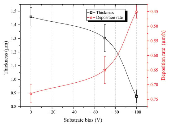
Figure 1.
Dependence of DR and thickness of TiCN coating on Us.
Figure 2 shows the surface and thickness of TiCN-coated samples after MS in the studied substrate bias voltage range. The SEM image shows that the morphology of the deposited coatings does not differ from each other. From the image’s analysis, it follows that the coating structure has a uniform and dense structure without pores, chips, and cracks. The deposited coating repeats the surface relief of the VT6 titanium substrate. In all experimental modes, the microstructure of the coatings has a similar appearance with lines from substrate microscratches, which remained after grinding during the substrate preparation. The reported coating thickness at 0 V is 1.45 µm thick on a glass substrate.
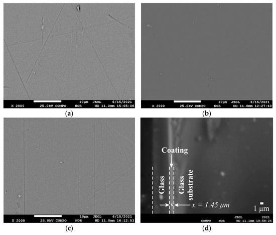
Figure 2.
SEM images of the morphology and coating thickness of TiCN coatings obtained at different substrate bias voltage: (a) 0; (b) −70 V; (c) −100 V; and (d) coating thickness obtained at without substrate bias voltage 0 V.
The effect of the applied negative substrate bias voltage on the chemical composition of TiCN coatings deposited at different Us values is shown in Table 1. The composition of the coating was obtained using EDX analysis over a surface area of 40 × 40 µm2 at a magnification of ×2000. The elemental composition of the one without voltage coating consists of titanium 47.6 at %, carbon 19.0 at %, and nitrogen 33.4 at %. There are some changes in the chemical composition as the bias voltage increases to −100 V, namely an increase in carbon to 34 at % and approximately a stable amount of nitrogen around 33–35 at %. Titanium decreases from 47.6 to 30 at %. The increase in the amount of carbon and reduction of titanium is associated with carburizing the surface of the titanium target with the continuation of the sputtering time, which creates favorable conditions in the plasma to form TiC rather than TiN.

Table 1.
Dependence of the elemental composition of TiCN coatings on Us.
Figure 3 shows the X-ray phase analysis of the TiCN coatings deposited at various negative substrate bias voltage. The diffractogram shows that three main phases are detected in all coatings: TiCN, TiN, and TiC. The structure of TiCN coatings changes from amorphous to crystalline, as can be seen from the picture. The samples obtained with substrate bias show narrower peaks presenting TiCN, TiN, and TiC compared to the without voltage coating, indicating good crystallinity. Table 2 shows percentage data on the phase composition of the coatings obtained at 0, −70 and −100 V. The main phase forming coatings during magnetron sputtering is titanium carbonitride. Its maximum content is found in the coating formed at a potential voltage of −70 V (58.2%).
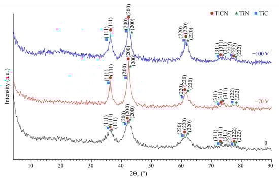
Figure 3.
Effect of substrate bias at deposition TiCN coating on diffractograms.
Table 2.
Percentages of TiCN coating phases depending on Us.
The wear resistance of TiCN coatings depends mainly on the microstructure, hardness, and adhesion, which are usually measured in terms of friction coefficient and wear mass loss [25]. The coefficient of friction (CoF) of all coatings was measured relative to Si3N4 balls. TiCN coatings generally have a low friction coefficient value. The graph of friction coefficient with an average value of deposited coatings at Us = 0, −70, −100 V, and titanium substrate VT6 is shown in Figure 4. The resulting coatings showed an average CoF value from 0.06 to 0.19. It can be seen that the sample deposited on the substrate bias of −70 V has a low CoF. In other cases, the CoF values are approximately the same, which are in the area of about 0.18. The CoF results are in good agreement with those obtained for TiCN films by Saoula N et al. [9,25]; however, the CoF for the −70 V sample is much lower than in these works. The composition of the transition layer and the friction interface should be considered concerning the change in CoF [26]. The low CoF behavior is explained by the formation of third bodies in the contact and the subsequent formation of a lubricating transition layer, which is mainly due to the increased carbon sp2 [27,28]. In addition, the elemental and phase analysis of this coating proves the increased carbon composition. In addition, a possible reason for the decrease in the CoF at −70 V may be an increase in hardness. According to [29,30], a decrease in the friction coefficient correlates with surface hardening.
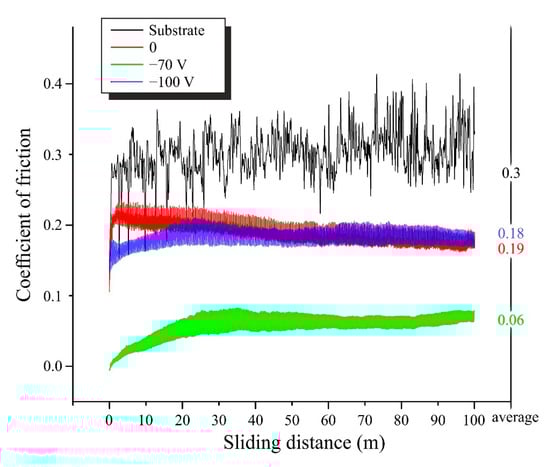
Figure 4.
CoF for titanium VT6 substrate and TiCN coatings obtained at Us = 0, −70, −100 V.
Tribological tests showed reduced wear in TiCN coatings obtained with substrate bias compared to without voltage coatings. Figure 5 shows the average CoF and wear rate (WR) for the VT6 substrate and TiCN coatings obtained at Us = 0, −70, and −100 V. The TiCN coatings deposited without voltage and at −100 V showed more similar CoF, but the WR differ significantly for them. The WR of the −100 V sample is almost two times lower than the WR of the sample without voltage. The best results among the obtained coatings were achieved by the coating deposited at −70 V with WR equal to 1.4 × 10⁻⁶ mm3/mN. This is due to the higher hardness, higher sp2 carbon content, and higher proportion of phase composition TiCN, which is consistent with the results of works [9,25]. The coatings wore approximately close to each other despite the significant difference in the average CoF values for −70 and −100 V. The −70 V sample showed a strong decrease in CoF, which was certainly due to the higher carbon content in its structure (34.4 at %), which promotes the growth of amorphous intergrain phases [17]. All obtained coatings show low CoF without sharp jumps in the graph, which indicates a high cohesive and adhesive strength of the formed coatings by the MS method [31].
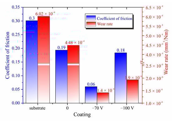
Figure 5.
Averaged CoF and WR for VT6 substrate and TiCN coatings obtained at Us = 0, −70, and −100 V.
Figure 6 shows optical micrographs of the wear track of TiCN coatings after a ball-on-disk wear test at a normal load of 1 N and a track length of 100 m, at a radius of 7 mm. All coatings show signs of abrasion. The coating obtained at −70 V has higher wear resistance, which is confirmed by the smallest width of the wear track and damage to the surface of the coating. This is due to higher hardness, higher carbon content, and low average coefficient of friction. The remaining coatings have approximately the same track width, although their wear rates differ significantly (Figure 5). At the site of groove formation on the coating surface deposited at a bias of 0 V, local areas with a changed color are visible. This indicates the development of tribochemical reactions between the coating and the Si3N4 ball. Perhaps this is due to a more significant temperature increase during friction in comparison with other samples. In the case of a coating obtained at −100 V, many scratches are observed in the center of the wear track, parallel to the sliding direction, which indicates the formation of wear products. It should be noted that at the coating −70 V, the surface of the wear track was covered with a smaller amount of powders of wear products, which was probably from products from the material of the ball. Thus, the analysis of the structure of the friction surface proves that the coating obtained under the conditions of deposition at a bias of −70 V has the best wear resistance among the considered coatings.
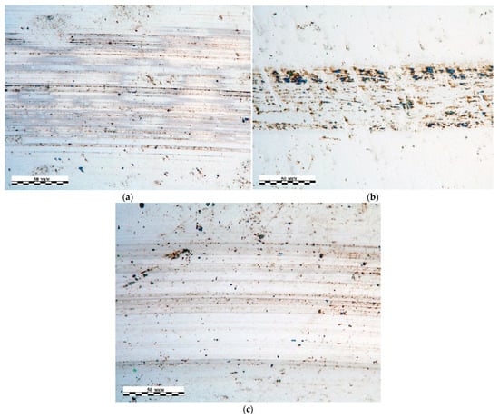
Figure 6.
Optical micrographs of wear track after tribological ball-on-disk test at a normal load of 1 N and a track length of 100 m for TiCN coatings obtained at different substrate bias voltage: (a) 0 V, (b) −70 V, (c) −100 V.
Figure 7 shows the changes in nanohardness (H) and Young’s modulus (E) of the coatings as well as the calculated H/E and H3/E2 values. Figure 7a shows that the nanohardness increases to a maximum value of H = 19 GPa for a coating applied with a voltage of −70 V. The Young’s modulus of the substrate showed a high value of E = 174 GPa, further starting at 145 GPa (0 V) and rising to 179.2 GPa for −100 V. The lowest nanohardness of 13.5 GPa and Young’s modulus of 145 GPa is obtained for the without-voltage TiCN coating when comparing the obtained coatings. The above nanohardness and friction coefficient data are not sufficient to demonstrate the tribological properties of the coatings. Such parameters as the ratio of nanohardness of coatings to Young’s modulus, H/E, and H3/E2 can be considered as an indicator of good resistance to mechanical degradation and destruction [32,33]. Higher values of H/E and H3/E2 can lead to lower wear/loss rates [34,35]. These values are not tribological parameters, though. Figure 7b shows the H/E and H3/E2 values for the substrate material and TiCN coatings obtained at Us = 0, −70, and −100 V. Using the substrate bias voltage leads to a 10% increase in H/E, H3/E2 by almost 2 times. The best H/E ratio and H3/E2 ratio is the coating obtained at Us = −70 V. This sample has a high H/E > 0.1 ratio, indicating that the coating has good fracture resistance, as reported in works [32,33]. This result is confirmed by wear tests, which showed the lowest wear rate of all magnetron sputtering coatings obtained.
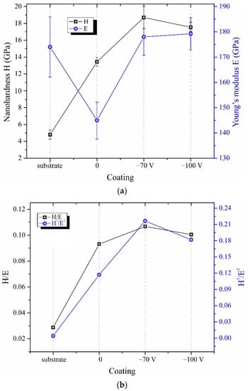
Figure 7.
Nanohardness of VT6 substrate and TiCN coatings obtained at Us = 0, −70, and −100 V: (a) nanohardness and Young’s modulus; (b) H/E and H3/E2 values for substrate and obtaining coatings.
4. Conclusions
TiCN coatings were deposited by reactive magnetron sputtering on a substrate with voltage in an argon–acetylene–nitrogen atmosphere. The influence of substrate bias on the deposition rate, elemental, and phase composition of the coatings were studied, and the nanohardness and tribological properties of the coatings were investigated.
The deposition rate of TiCN coatings decreases as the substrate voltage increases to −100 V. It was shown that the elemental composition of the resulting coatings can vary significantly depending on the application of voltage to the substrate. The application of substrate bias voltage leads to an increase in carbon and a decrease in titanium concentrations. The crystallinity of the obtained coatings increases with increasing bias voltage up to −100 V.
The largest fraction of the TiCN phase in the coatings is formed at −70 V. A low coefficient of friction is fixed on TiCN coatings obtained at −70 V. Tribological tests have determined that substrate bias voltage reduces the wear rate of TiCN coatings by increasing the nanohardness. The nanohardness results show that substrate bias voltage during coating deposition leads to higher nanohardness and Young’s modulus values, as well as their ratio.
Comprehensive research has resulted in the determination of the preferred mode with a potential voltage of −70 V, where TiCN coatings with low friction coefficient, wear rate, and high nanohardness are formed, and an acceptable composition is formed. Thus, as a result of the obtained dependences, the most preferred mode of the obtaining coating from presented, which is resistant to tribodestruction, was revealed.
Author Contributions
Conceptualization, A.M. and A.P.; methodology, A.K.; software, A.K.; validation, A.M. and A.P. and W.W.; formal analysis, A.K.; investigation, A.M. and A.K.; resources, A.K.; data curation, A.M. and A.K.; writing—original draft preparation, A.K.; writing—review and editing, A.K. and Z.A.; supervision, A.M.; project administration, A.M.; funding acquisition, A.M. All authors have read and agreed to the published version of the manuscript.
Funding
This research was funded by the Science Committee of the Ministry of Education and Science of the Republic of Kazakhstan, Grant No. AP08857049.
Institutional Review Board Statement
Not applicable.
Informed Consent Statement
Not applicable.
Data Availability Statement
The data and results presented in this study are available in the article.
Conflicts of Interest
The authors declare no conflict of interest.
References
- Li, Z.; Di, S. The microstructure and wear resistance of microarc oxidation composite coatings containing nano-hexagonal boron nitride (HBN) particles. J. Mater. Eng. Perform. 2017, 26, 1551–1561. [Google Scholar] [CrossRef]
- Ramazanova, J.M.; Zamalitdinova, M.G. Physical and mechanical properties investigation of oxide coatings on titanium. Complex Use Miner. Resour. 2019, 2, 34–41. [Google Scholar] [CrossRef]
- Yeshmanova, G.B.; Smagulov, D.U.; Blawert, C. Plasma electrolytic oxidation technology for producing protective coatings of aluminum alloys. Complex Use Miner. Resour. 2021, 2, 78–93. [Google Scholar] [CrossRef]
- Chen, L.; Wang, S.Q.; Zhou, S.Z.; Li, J.; Zhang, Y.Z. Microstructure and mechanical properties of Ti(C,N) and TiN/Ti(C,N) multilayer PVD coatings. Int. J. Refract. Met. Hard Mater. 2008, 26, 456–460. [Google Scholar] [CrossRef]
- Ajikumar, P.K.; Kamruddin, M.; Kalavathi, S.; Balamurugan, A.K.; Kataria, S.; Shankar, P.; Tyagi, A.K. Synthesis, characterization and evaluation of titanium carbonitride surface layers with varying concentrations of carbon and nitrogen. Ceram. Int. 2012, 38, 2253–2259. [Google Scholar] [CrossRef]
- Bull, S.J.; Bhat, D.G.; Staia, M.H. Properties and performance of commercial TiCN coatings. Part 2: Tribological performance. Surf. Coat. Technol. 2003, 163–164, 507–514. [Google Scholar] [CrossRef]
- Razmi, A.; Yeşildal, R. Microstructure and mechanical properties of TiN/TiCN/TiC multilayer thin films deposited by magnetron sputtering. Int. J. Innov. Res. Rev. 2021, 5, 15–20. [Google Scholar] [CrossRef]
- Chen, R.; Tu, J.P.; Liu, D.G.; Mai, Y.J.; Gu, C.D. Microstructure, mechanical and tribological properties of TiCN nanocomposite films deposited by DC magnetron sputtering. Surf. Coat. Technol. 2011, 205, 5228–5234. [Google Scholar] [CrossRef]
- Saoula, N.; Madaoui, N.; Tadjine, R.; Erasmus, R.M.; Shrivastava, S.; Comins, J.D. Influence of substrate bias on the structure and properties of TiCN films deposited by radio-frequency magnetron sputtering. Thin Solid Film. 2016, 616, 521–529. [Google Scholar] [CrossRef]
- Matei, A.A.; Pencea, I.; Stanciu, S.G.; Hristu, R.; Antoniac, I.; Ciovica, E.; Sfat, C.E.; Stanciu, G.A. Structural characterization and adhesion appraisal of TiN and TiCN coatings deposited by CAE-PVD technique on a new carbide composite cutting tool. J. Adhes. Sci. Technol. 2015, 29, 2576–2589. [Google Scholar] [CrossRef]
- Zhu, L.; He, J.; Yan, D.; Liao, H.; Zhang, N. Oxidation Behavior of Titanium Carbonitride Coating Deposited by Atmospheric Plasma Spray Synthesis. J. Therm. Spray Technol. 2017, 26, 1701–1707. [Google Scholar] [CrossRef]
- Yang, Y.; Guo, N.; Li, J. Synthesizing, microstructure and microhardness distribution of Ti−Si−C−N/TiCN composite coating on Ti−6Al−4V by laser cladding. Surf. Coat. Technol. 2013, 219, 1–7. [Google Scholar] [CrossRef]
- Yang, Y.L.; Yao, W.M.; Zhang, H.Z. Phase constituents and mechanical properties of laser in-situ synthesized TiCN/TiN composite coating on Ti-6Al-4V. Surf. Coat. Technol. 2010, 205, 620–624. [Google Scholar] [CrossRef]
- Zhang, J.; Xue, Q.; Li, S. Microstructure and corrosion behavior of TiC/Ti(CN)/TiN multilayer CVD coatings on high strength steels. Appl. Surf. Sci. 2013, 280, 626–631. [Google Scholar] [CrossRef]
- Fang, T.H.; Jian, S.R.; Chuu, D.S. Nanomechanical properties of TiC, TiN and TiCN thin films using scanning probemicroscopy and nanoindentation. Appl. Surf. Sci. 2004, 228, 365–372. [Google Scholar] [CrossRef]
- Restello, S.; Boscarino, D.; Rigato, V. A study of Ti–C–N(H) and Ti:CNx(H) coatings grown with a magnetron sputtering/PECVD hybrid deposition process. Surf. Coat. Technol. 2006, 200, 6230–6234. [Google Scholar] [CrossRef]
- Tillmann, W.; Grisales, D.; Tovar, C.M.; Contreras, E.; Apel, D.; Nienhaus, A.; Stangier, D.; Lopes Dias, N.F. Tribologicalbehaviour of low carbon-containing TiAlCN coatings deposited by hybrid (DCMS/HiPIMS) technique. Tribol. Int. 2020, 151, 106528. [Google Scholar] [CrossRef]
- Auciello, O.; Engemann, J. Multicomponent and Multilayered Thin Films for Advanced Microtechnologies: Techniques, Fundamentals and Devices; Springer: Bad Windsheim, Germany, 1993; p. 663. [Google Scholar]
- Polcar, T.R.; Novak, P.; Siroky, P. The tribological characteristics of TiCN coating at elevated temperatures. Wear 2006, 260, 40–49. [Google Scholar] [CrossRef]
- Zheng, X.H.; Tu, J.P.; Gu, B.; Hu, S.B. Preparation and tribological behavior of TiN/a-C composite films deposited by DC magnetron sputtering. Wear 2008, 26, 261–265. [Google Scholar] [CrossRef]
- Hsieh, J.H.; Wu, W.; Li, C.; Yu, C.H.; Tan, B.H. Deposition and characterization of Ti(C,N,O) coatings by unbalanced magnetron sputtering. Surf. Coat. Technol. 2003, 163, 233–237. [Google Scholar] [CrossRef]
- Correa, J.F.; Aperador, W.; Caicedo, J.C.; Alba, N.C.; Amaya, C. Structural, mechanical and tribological behavior of TiCN, CrAlN and BCN coatings in lubricated and nonlubricated environments in manufactured devices. Mater. Chem. Phys. 2020, 252, 123164. [Google Scholar] [CrossRef]
- Wang, H.; Zhang, S.; Li, Y.; Sun, D. Bias effect on microstructure and mechanical properties of magnetron sputtered nanocrystalline titanium carbide thin films. Thin Solid Film. 2008, 516, 5419–5423. [Google Scholar] [CrossRef]
- Wang, Z.; Zhang, D.; Ke, P.; Liu, X.; Wang, A. Influence of substrate negative bias on structure and properties of TiN coatings prepared by hybrid HIPIMS method. Mater. Sci. Technol. 2015, 31, 37–42. [Google Scholar] [CrossRef]
- Mechri, H.; Saoula, N.; Madaoui, N. Friction and wear behaviors of TiCN coating treated by R.F. magnetron sputtering. In Proceedings of the 7th African Conference on Non Destructive Testing ACNDT 2016 & the 5th International Conference on NDT and Materials Industry and Alloys (IC-WNDT-MI): Research Center in Industrial Technologies CRTI, Algiers, Algeria, 31 July 2016. [Google Scholar]
- Cheng, Y.H.; Browne, T.; Heckerman, B.; Meletis, E.I. Influence of the C content on the mechanical and tribological properties of the TiCN coatings deposited by LAFAD technique. Surf. Coat. Technol. 2011, 205, 4024–4029. [Google Scholar] [CrossRef]
- Mahdipoor, M.; Mahboubi, F.; Ahangarani, S.; Raoufi, M.; Elmkhah, H. The Influence of Plasma Nitriding Pre-Treatment on Tribological Properties of TiN Coatings Deposited by PACVD. J. Mater. Eng. Perform. 2011, 20, 1–7. [Google Scholar] [CrossRef]
- Luo, D.; Zhou, Q.; Ye, W.; Ren, Y.; Greiner, C.; He, Y.; Wang, H. Design and characterization of self-lubricating refractory high entropy alloy-based multilayered films. ACS Appl. Mater. Interfaces 2021, 13, 55712–55725. [Google Scholar] [CrossRef] [PubMed]
- Rakhadilov, B.; Buitkenov, D.; Sagdoldina, Z.; Seitov, B.; Kurbanbekov, S.; Adilkanova, M. Structural Features and Tribological Properties of Detonation Gun Sprayed Ti–Si–C Coating. Coatings 2021, 11, 141. [Google Scholar] [CrossRef]
- Rakhadilov, B.; Buitkenov, D.; Idrisheva, Z.; Zhamanbayeva, M.; Pazylbek, S.; Baizhan, D. Effect of Pulsed-Plasma Treatment on the Structural-Phase Composition and Tribological Properties of Detonation Coatings Based on Ti–Si–C. Coatings 2021, 11, 795. [Google Scholar] [CrossRef]
- Kenzhegulov, А.К.; Mamayeva, A.A.; Panichkin, A.V. Adhesion properties of calcium phosphate coatings on titanium. Complex Use Miner. Resour. 2017, 3, 35–41. [Google Scholar]
- Musil, J.; Vlcek, J. Magnetron sputtering of hard nanocomposite coatings and their properties. Surf. Coat. Technol. 2001, 142, 557–566. [Google Scholar] [CrossRef]
- Musil, J.; Jirout, M. Toughness of hard nanostructured ceramic thin films. Surf. Coat. Technol. 2007, 201, 5148–5152. [Google Scholar] [CrossRef]
- Leyland, A.; Matthews, A. On the significance of the H/E ratio in wear control: A nanocomposite coating approach to optimized tribological behavior. Wear 2000, 246, 1–11. [Google Scholar] [CrossRef]
- Hua, D.; Xia, Q.; Wang, W.; Zhou, Q.; Li, S.; Qian, D.; Shi, J.; Wang, H. Atomistic insights into the deformation mechanism of a CoCrNi medium entropy alloy under nanoindentation. Int. J. Plast. 2021, 142, 102997. [Google Scholar] [CrossRef]
Publisher’s Note: MDPI stays neutral with regard to jurisdictional claims in published maps and institutional affiliations. |
© 2022 by the authors. Licensee MDPI, Basel, Switzerland. This article is an open access article distributed under the terms and conditions of the Creative Commons Attribution (CC BY) license (https://creativecommons.org/licenses/by/4.0/).