1. Introduction
Copper (Cu) has been widely used in the electric power industry due to its high electrical and thermal conductivities, adequate strength, and low cost [
1,
2,
3]. However, equipment made by copper is easily oxidized in the natural environment, and the copper oxide film is not as dense as an aluminum oxide film, to form a protective effect on itself. Furthermore, the oxide film of copper directly affects its own electrochemical performance, such as electrical and thermal conductivity. Due to the high resistance of the oxide film, considerable amounts of power loss and heat are generated at the isolating switch and other joint equipment, which further oxidize the copper equipment, thus causing power breakdowns. According to statistics, about 20% of power equipment failures are caused by overheating of the contact such as the guide joint and terminal post of the equipment, and almost 80% of power failures are caused by overheating of the contact during the peak period of power consumption. In order to avoid this, some strategies were applied to protect power equipment joints from corrosion or damage, such as electric brush-plating and electrochemical deposition methods [
4,
5,
6]. The electric brush-plating technique, in which equipment surfaces are coated with a coating layer by a coating solution, was widely applied in the surface protecting and machine-building industries [
7]. Due to its advantages of low cost, easy movability, high deposition rate, and simple device, it was widely used in repairing isolating switches and other joint equipment.
In the industry, it is common practice to coat metals with silver to ensure a more stable, less oxidized contact surface and lower inherent joint resistance [
8]. Güler et al. prepared a new copper-based electrical contact material based on copper substrate and silver nickel-alloy coating, and results showed that the wear and arc-erosion performances of the materials could be up to 10 times greater than the pure copper [
9]. However, traditional silver plating solution usually contains other heavy metals (such as chromium, lead, etc.) and cyanogenic compounds, leading to toxic gases and wastewater that may be released during the brush-plating process, which would cause great harm to people’s health and the environment. Therefore, researchers made some efforts to improve the silver brush-plating solution, such as adding some rare-earth elements. Montemor et al. obtained bis-aminosilane coating on AZ31 magnesium alloy by brushing plating, and the results revealed that the corrosion rate of the Mg AZ31 substrates was significantly slowed with the addition of the rare-earth salt [
10]. Zhang et al. analyzed the effect of rare-earth content on the properties of nickel plating and nickel–cobalt alloy, and the results showed that rare-earth elements could reduce the porosity and crack density of the coating and could also make the coating grain more uniform [
11]. Yang et al. prepared the double rare-earth-modified coating film by using rare-earth lanthanum and cerium on the surface of magnesium alloy [
12]. The results showed that the surface cracks of the coating significantly reduced and the corrosion resistance, and oxidation resistance improved.
Cerium is the most abundant rare-earth element in the earth’s crust. Due to its excellent chemical properties, cerium-based oxides have widely been used in many advanced function materials, such as catalysis, corrosion prevention, electrochemical cells, metal plating, biomaterials, etc. Rare-earth elements are used as special additives in the electroplating solution, which can obviously improve the properties of coating layers [
13,
14,
15,
16,
17,
18]. However, there are few reports on the effect of silver brush-plating solution with cerium-based oxides for repairing isolating switches or other joint equipment.
Therefore, in this study, an environmentally friendly coating silver brush-plating solution based on silver nitrate and sulfosalicylic acid was obtained, and the physicochemical properties and application effect of the silver coating layer were also characterized. We believe that the proposed system based on the environmentally friendly silver-coating solution can widely be used in the power industry.
2. Experimental
2.1. Plating Composition
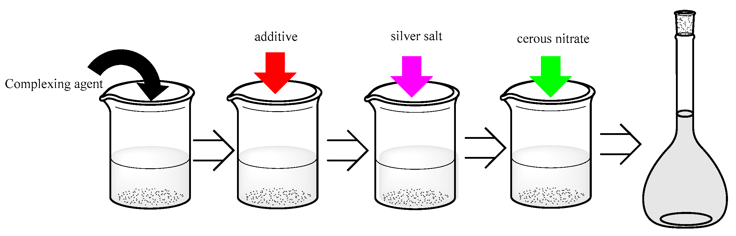
Preparation of the additive: imidazole, N, N-dimethylformamide, and hexamethylenetetramine were mixed by the weight of 100:1:1.
The silver brush-plating solution was made by adding the above drugs listed in
Table 1 into a beaker and stirring at room temperature with a homogenizer for at least 20 min. Afterward, the pH of the solution was adjusted to weakly alkaline (pH = 8–9) by ammonium hydroxide and nitric acid. The preparation process was shown in
Figure 1.
2.2. Copper Sheet Pretreatment
Preparation of the alkaline electrolyte: a total of 20 g sodium hydroxide, 20 g sodium carbonate, 70 g trisodium phosphate dodecahydrate, and 2 g sodium chloride were added in deionized water, to make 1000 mL of solution.
Preparation of the citric acid type activation liquid: a total of 130 g sodium citrate dihydrate, 90 g citric acid monohydrate, and 2 g nickel chloride hexahydrate were added in deionized water, to make 1000 mL; then, the pH of it was adjusted to 3.5–4 by hydrochloric acid.
The substrate was made of copper having a purity of 99.97% and a size of 50 mm × 20 mm × 0.2 mm. The bare copper was first deoxidized by polishing in one direction with 2000 mesh sandpaper 10 times, to obtain a copper sheet that was bright and flat on the macroscopic surface. Then, the oil removal treatment was carried out with an alkaline electrolyte, and the electrolytic copper plate was activated by a citric acid-type activation liquid. The treated copper sheet was rinsed with deionized water, blown dry, and then immersed in alcohol for use.
2.3. Experimental Process and Post-Processing
An electroplating pen was used as the anode, and the copperplate to be brushed was connected to the cathode. The voltage range during brush plating was set to 0.5–2.0 V. After brush plating, the residual brush-plating solution on the surface of the coating was rinsed with deionized water and dried quickly.
2.4. Scanning Electron Microscopy
Silver plating was photographed at different magnifications using a scanning electron microscope (SEM, 300VP, Zeiss, Jena, Germany). The surface of the coating was microscopically enlarged to observe the microscopic surface morphology of the silver coating and determine whether there were obvious defects, uneven grain distribution, peeling of the coating from the substrate, or foaming. The section of the coating was mainly to observe the connection between the coating and the substrate and the thickness of the coating. By microscopic enlargement, the state of the junction of the two phases was observed, and the approximate thickness of the silver coating was measured by the dimensioning of the scanning electron microscope.
2.5. Characterization of Coating Adhesion
Two methods outlined in the QB/T 3821–1999 Light Industry Standards of the People’s Republic of China were used to evaluate the coating adhesion strength. The first method uses a hard steel knife to draw scratches every 1 mm along the horizontal and vertical directions on the coating surface. These scribe lines divide the surface of the base copper sheet into 1 mm grid squares. Whether the coating flaked off the substrate differentiated good and bad adhesion.
Another method was selected in which a copper is coated with silver coating, and the copper substrate is then bent back and forth repeatedly until the copper piece breaks while observing the fracture and judging the adhesion of the coating by whether the plating layer and the substrate fall off or separate.
The copper sheets subjected to the scratch test were heat treated at 20, 30, 50, 70, 90 and 110 °C, for 2 h and under the same conditions. Then, the scratched portion was enlarged by a polarizing microscope, the connection between the silver plating layer and the substrate at the scratch was observed, and the influence of temperature on the adhesion property of the silver plating layer was compared.
2.6. Electrochemical Experiment
The electrochemical properties of the coating were analyzed by a three-electrode system [
19]. The silver coating layer, saturated calomel electrode (SCE), and platinum wire were used as working electrode, reference electrode, and counter electrode, respectively. A 3.5% sodium chloride solution was adjusted to pH 5 and used as the electrolyte in this system. The back side of the brush-plating layer was coated with a resin before conducting the electrochemical experiment. At room temperature, the working electrode was placed in the electrolyte, to measure the open circuit potential for 30 min, and the polarization curve of the sample was measured after the working electrode stabilized. The scanning interval was ±400 mV relative to the open circuit potential, and the scanning rate was 1 mV/s. Each sample was tested three times, and the corrosion current and corrosion voltage of the sample were obtained from the average value of the test.
2.7. Metal Element Distribution
The elements on the surface of the coating and their distribution were investigated by energy-dispersive X-ray spectrometers (EDX, 300VP, Zeiss, Jena, Germany). and elemental mappings. The crystal of the coating layer was tested by XRD (D8 advance, Karlsruhe, Germany).
2.8. Application Measurement
Firstly, an isolating switch of large-scale power equipment was repaired with the silver coating solution, and then, the power equipment was normally run for 2 days, after which the temperature of the repaired isolating switch was tested by an infrared thermal imager (GD-E4, Guodian west high, Wuhan, China). The temperature of the unrepaired isolating switch was also tested by the same conditions.
3. Results and Discussion
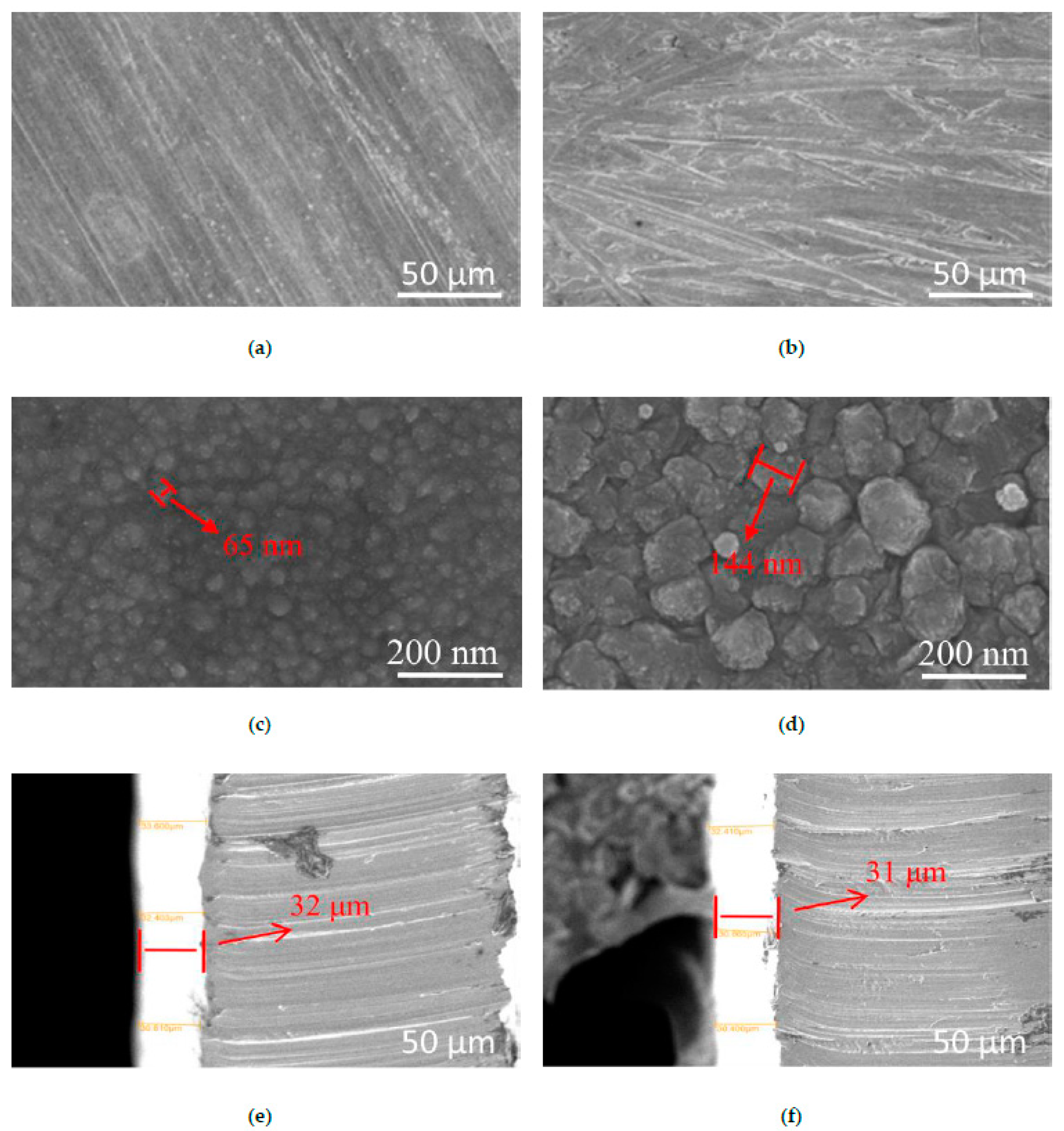
The defects and flatness of the microstructure and the grain size and arrangement of the metal particles can preliminarily reflect the basic performance characteristics of the coating.
Figure 2 shows the surface and section morphologies, when the coating based on the dosage of silver nitrate, sulfosalicylic acid, additive, cerium nitrate, ammonium acetate, polyethylene glycol 400, and the number of brush-plating operations were 10, 50, 55, 1, 10 and 10 g/L, and 8 times, respectively.
As shown in
Figure 2a,b, the low magnification map showed that the microstructures of the silver plating layers with or without adding cerium nitrate were rough, continuous, and still had obvious scratches, but the silver-plating layer with added cerium nitrate was obviously smoother than that without cerium nitrate. It can be seen that as the magnification increased, the microstructures of the plating layers were obviously changed. The silver-plated crystals on the surface of the plating layers with added cerium nitrate were denser and more ordered, with smaller size crystals, and had fewer defects on the surface than those without cerium nitrate. When the dosage of cerium nitrate was 1.0 g/L, the crystal grains were decreased from 144 nm to 65 nm [
20]. Wang et al. observed a similar phenomenon; they obtained nickel-based alloy power with different content of CeO
2 or La
2O
3, and their results showed that additions of rare-earth oxide CeO
2 or La
2O
3 could refine and purify the microstructure of coatings and reduce the dilution of clad material from the substrate [
21].
This phenomenon indicated that the addition of cerium nitrate could make the grain size more uniform and finer, reduce the porosity of the coating and the crack density of the silver layer, and make the grains more orderly. The same phenomenon was found by Zhang et al., who added rare-earth elements (Sc
2O
3, Y
2O
3, and La
2O
3) to aluminum matrix composite coatings [
22]. From the images of the cross-section of the coating, the silver coating and the copper substrate all had an obvious, homogenous, and tight interface with or without cerium nitrate, and the thicknesses of the coating were all over 30 μm, which could meet the needs of the power industry.
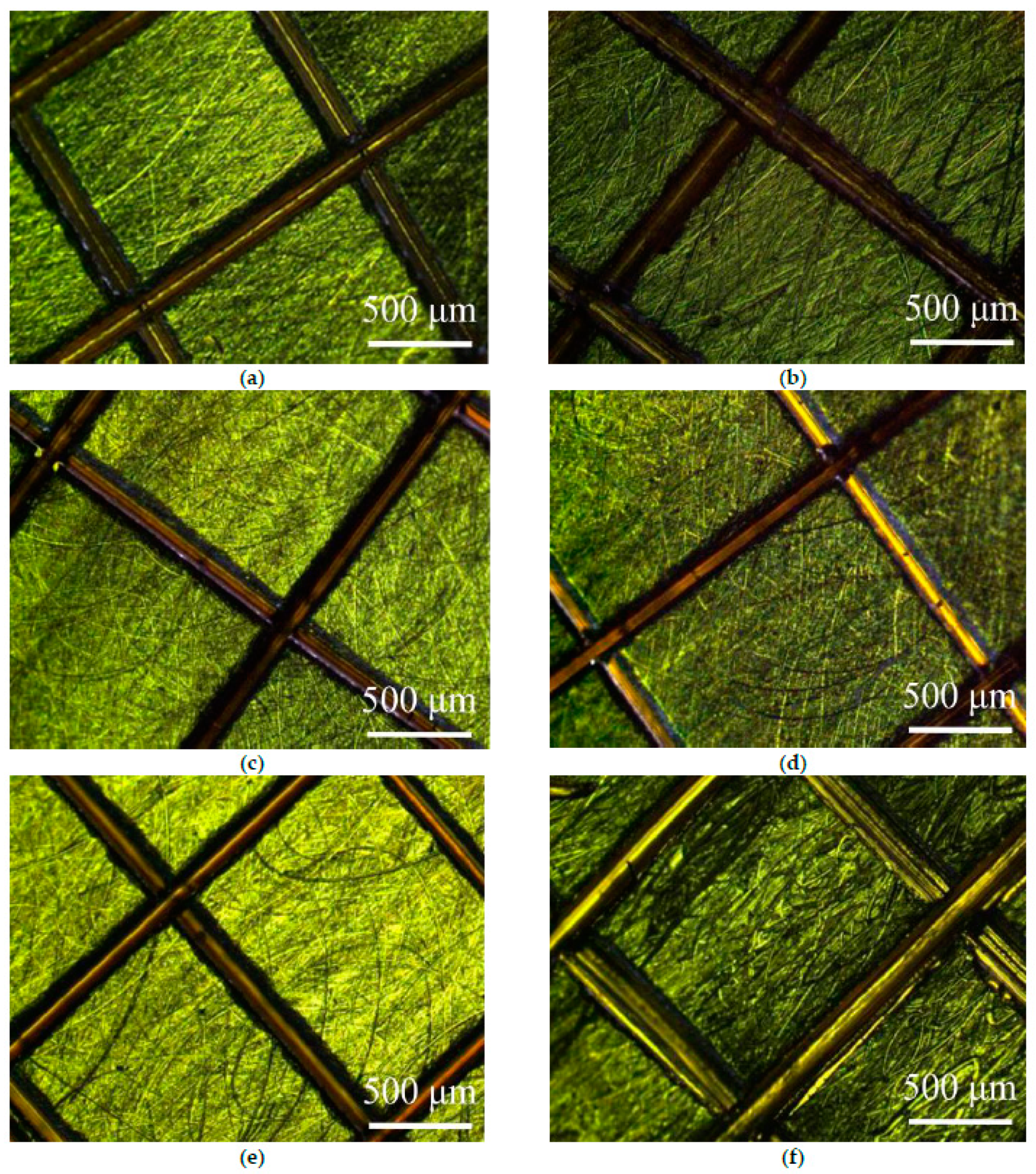
Figure 3 shows a microscopically enlarged view of the silver-plating layer’s scratch test with treatment at different temperature conditions. It was found that all coating surfaces at different temperatures did not have foaming or detachment from the substrate. In addition, there were no defects or debris on the scratch. The results showed that the coating has good adhesion on the glistening surface of the substrate at the temperature range of 20–110 °C.
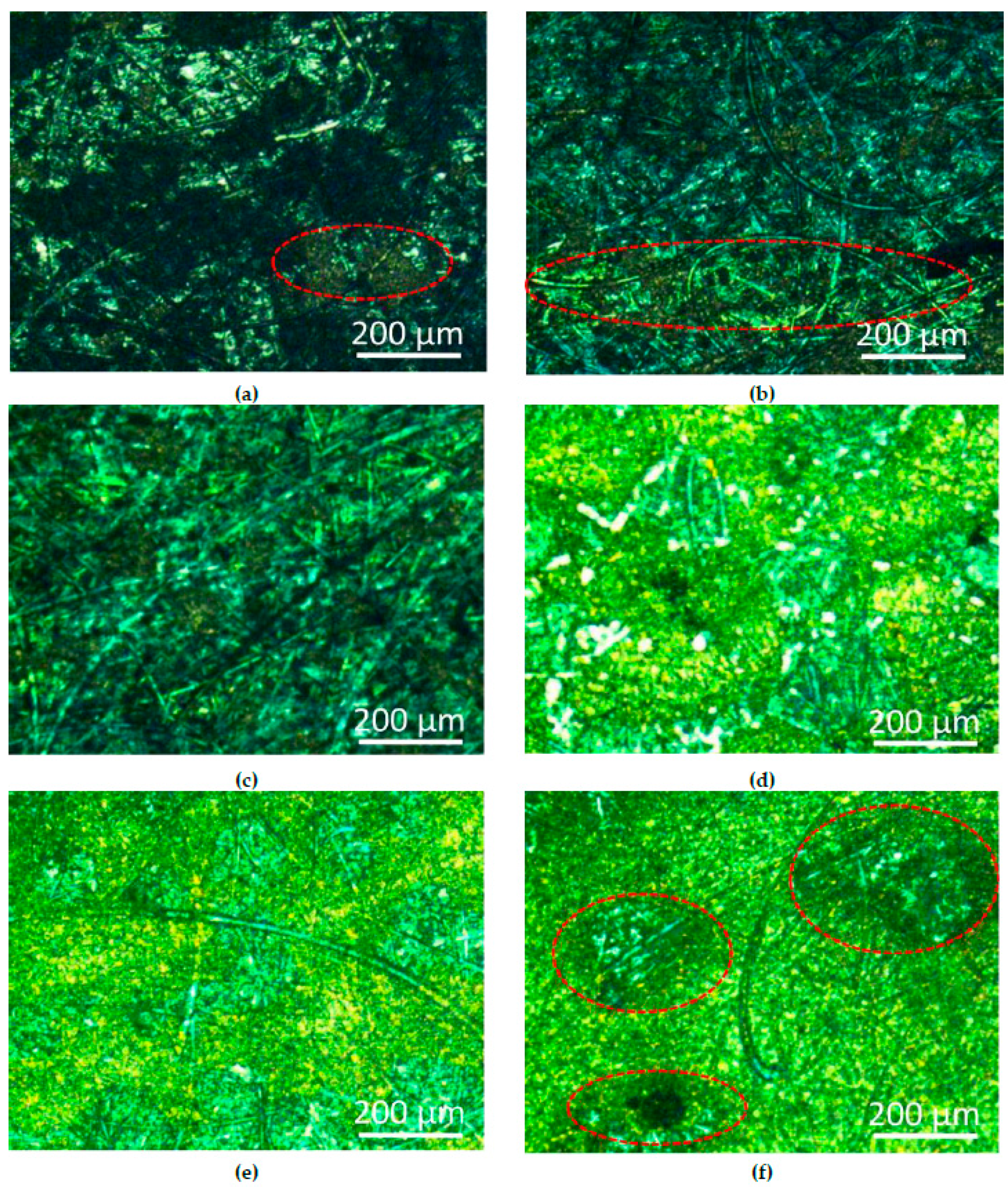
In
Figure 4a,c,e are corrosion micrographs of the silver coating that contained 1.0 g/L cerium nitrate.
Figure 4b,d,f are microscopic images of cerium nitrate-free coatings. It can be seen from these images that after 1-day immersion, a slight amount of yellow rust spots began to appear on the surface of the coating that contained cerium nitrate, but the rust spots of the cerium nitrate-free coating were more obvious. After 5 days, there were some scattered rust spots on the surface of the coating that contained cerium nitrate-free coating, and the silver layer was disappeared (
Figure 4d). After 10 days of immersion, the surface of the silver coating that contained cerium nitrate was basically corroded, but the copper substrate of the control group underwent serious corrosion. The results showed that the corrosion of the coating in brine is a slow process, and the addition of cerium nitrate to the system can slow the corrosion rate of the coating to some extent.
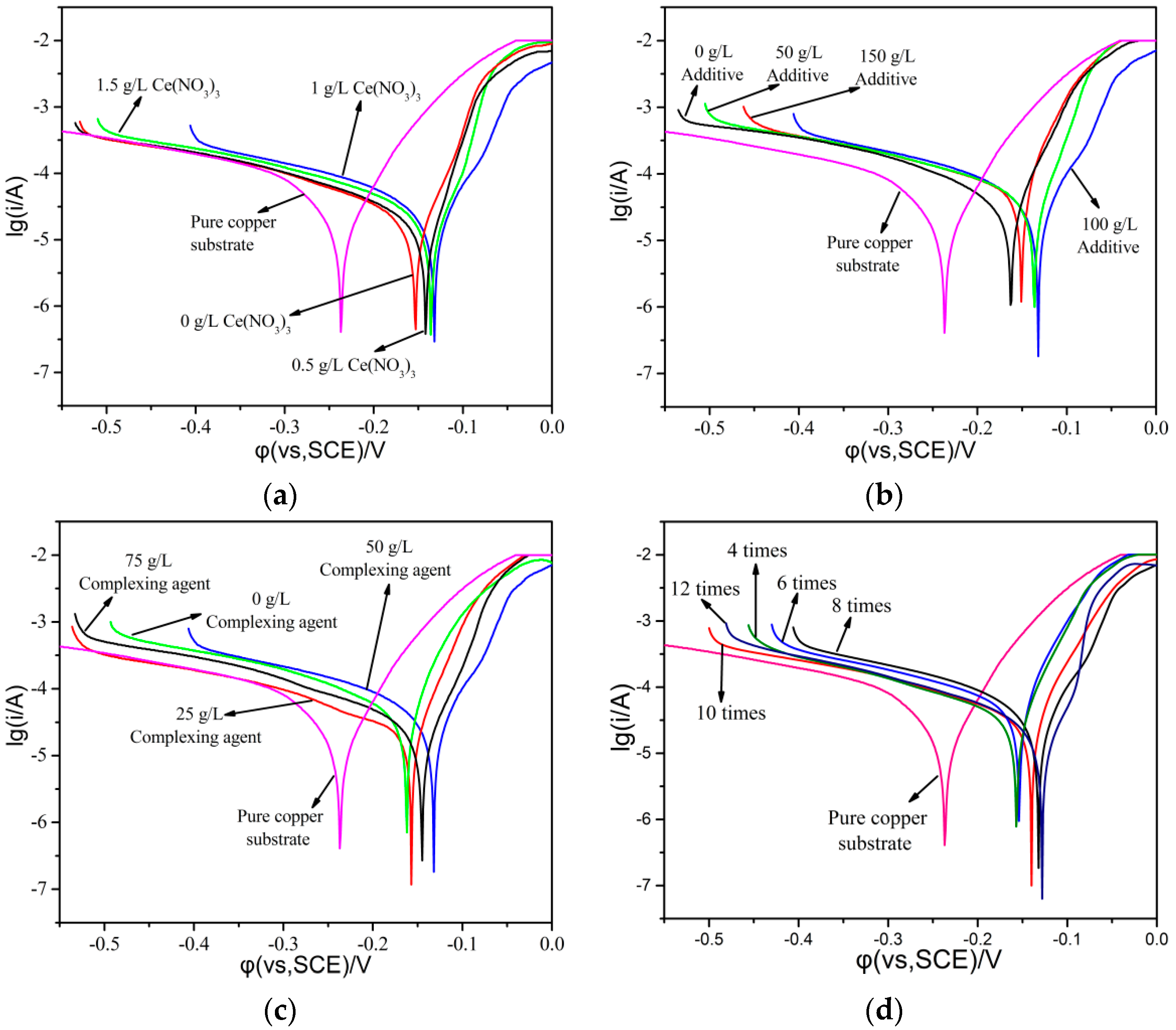
In order to compare the influence of various factors in the plating solution on the corrosion resistance of the coating, a Tafel polarization curve test was carried out for different rare-earth contents, brush-plating times, additive dosages, and complexing agent dosages, as shown in
Figure 5. The higher the self-corrosion voltage, and the smaller the self-corrosion current, the better the corrosion resistance of the coating, and the slower the corrosion rate. It could be clearly seen that the slopes of the Tafel curve were approximately the same. The corrosion current and corrosion voltage of the coating layer were changed by different conditions [
23]. When cerium nitrate was added to the coating solution, the corrosion voltage of the coating layer was first increased and then decreased, reaching the maximum value of the coating when the dosage of cerium nitrate was 1.0 g/L, which indicated that this dosage was best. When different amounts of additive content were incorporated, the corrosion voltage of the coating was also first increased and then decreased, and reached the maximum value when the additive was 50 g/L. The corrosion voltage of the coating layer reached the maximum value when the content of the complexing agent was 50 g/L, while at the same time, the corrosion currents of the layer were slightly changed, which indicated that the best content of the complexing agent was 50 g/L based on these data. As for the number of brush plating, it was found that the corrosion voltage of the coating layer was gradually increased with the brush-plating times, but when the brush-plating times increased from 8 to 12, the corrosion current and corrosion voltage of the coating layer had minimally changed. In order to save costs, the best brush-plating time was chosen as 8.
The electrochemical parameters of the polarization curve were numerically fitted. The results are shown in
Table 2. It can be seen from
Table 2 that with the increase in cerium nitrate content, additive content, complexing agent content, and brush-plating times, the self-corrosion potential (E
corrr) of the coating first increased and then decreased, and the self-corrosion potential (E
corrr) of the coating increased with the number of brush plating. The self-corrosion current (I
corr) had a poor regularity, but the self-corrosion current at the maximum of the self-corrosion potential was basically at a low level [
24,
25]. The results showed that the preferred values of silver nitrate content, sulfosalicylic acid content, additive content, cerium nitrate content, ammonium acetate content, polyethylene glycol 400 content, and the number of brush-plating operations were 10, 50, 55, 1, 10 and 10 g/L, and 8 times, respectively.
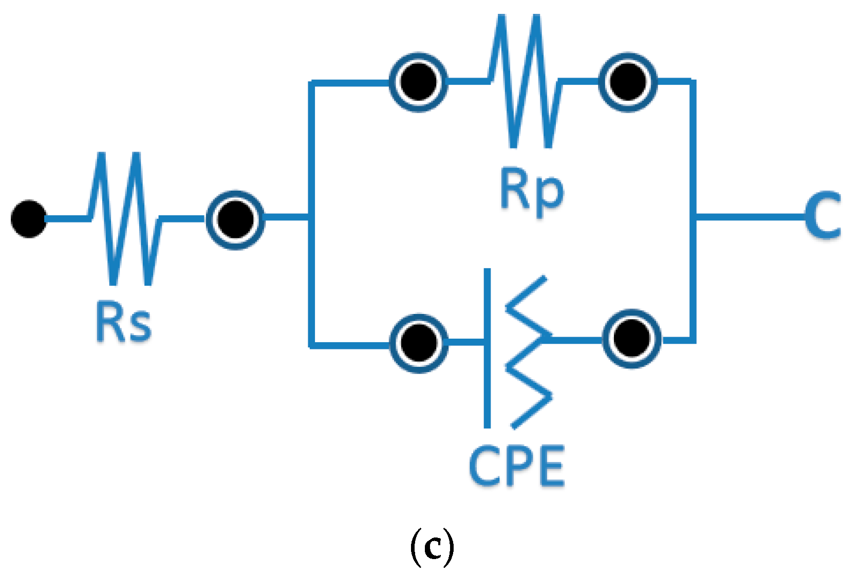
Figure 6 shows alternating current impedance spectra of the copper sheet before and after brush plating in a 3.5% sodium chloride solution, and the equivalent electrical circuit of the system is also shown in
Figure 6.
It can be seen from the impedance map that the slope of the low-frequency region of all curves is about 1, which indicates that the roughness of the silver coating in this experiment was not large or flat. It can be seen from the high-frequency region of the curve that the high-frequency capacitive arc resistance of the silver coating layer first increased and then decreased with the addition of a complexing agent or cerium nitrate, which indicated that the shielding ability of the coating first increased and then decreased. Additionally, the highest of the high-frequency capacitive arc resistance could be obtained with the dosage of a complexing agent or cerium nitrate were 50 g/L and 1.0 g/L, which corresponded to the corrosion voltage of the coating layer.
As shown in
Figure 7 and
Figure 8 and
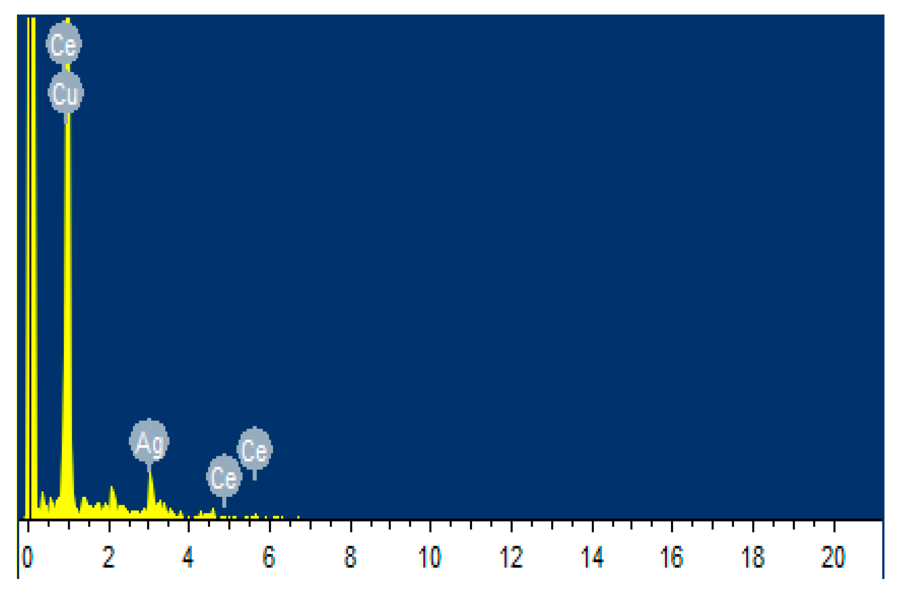
Table 3, the elemental composition and distribution of the coating were analyzed by a combination of EDS and element mapping. As can be seen from
Figure 7 and
Table 3, the surface of the coating contained Ag, Ce, C, Cu, and Au species elements, wherein the silver was the most abundant, reached 70.78% (weight), where the C probably attributed to the organic component that was added to the coating solution, the gold was due to the gold-spraying process before the test, and Cu was the matrix material. This indicated that the coating layer was based on silver.
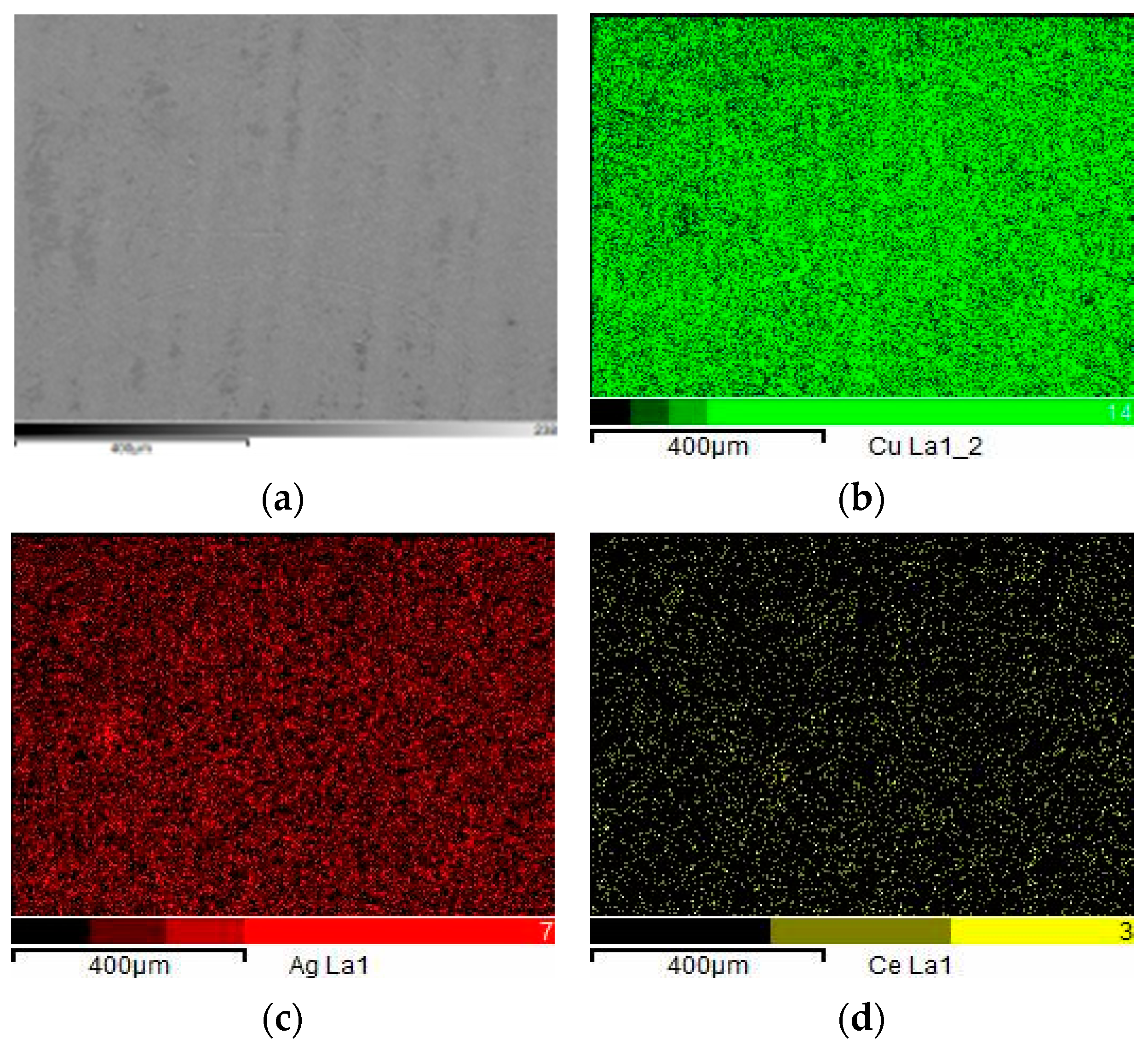
As evident from
Figure 8, in which the elemental composition of the coating can be clearly seen, the silver element was uniformly coated on the surface of the copper layer substrate, and the small amount of cerium element was homogeneously dispersed in the silver coating layer, which indicated that the coating solution has great brush-plating property, stability, and homogeneity.
In order to further verify the silver crystal, the XRD results of the silver coating layer are shown in
Figure 9. It was found that four intense diffraction peaks appeared at (2θ)—38.07°, 43.33°, 50.37°and 74.15°, respectively. The peak (2θ = 38.07°) was attributed to the 200 plane of silver oxide [
26], while the peaks (2θ = 43.33°, 50.37°, and 74.15°) corresponded to the copper’s 111 plane, 200 plane, and 220 plane, respectively [
27]. The result suggested that the silver coating layer was the main silver oxide.
5. Conclusions
A bright and compact silver coating on a copper sheet was successfully prepared by a coating solution without cyanogen, and the coating solution was successfully applied in repairing the transformer’s isolating switch. Results showed that good stability, dispersion, and corrosion resistance of the silver coating solution can result from its preparation with silver nitrate and sulfosalicylic acid. The incorporation of cerium nitrate obviously improved the physicochemical properties and corrosion resistance of the silver coating layer.
When the dosages of silver nitrate, sulfosalicylic acid, additive, cerium nitrate, ammonium acetate, and polyethylene glycol 400 were 10, 50, 55, 1, 10, and 10 g/L, respectively, the best silver coating solution was obtained. Additionally, when the number of brush plating was eight, the silver coating layer based on the best silver coating solution could reach 30 μm, with good adhesion to the copper substrate, fully meeting the requirements for power equipment repair. This system showed great potential for repairing power equipment.


