Article

The Corrosion Behavior of Al-Cu-Li Alloy in NaCl Solution

1
College of Mechanical and Electrical Engineering, Nanjing University of Aeronautics and Astronautics, Nanjing 210016, China
2
School of Mechanical Engineering, Anhui University of Technology, Ma’anshan 243032, China
*
Author to whom correspondence should be addressed.
Coatings 2022, 12(12), 1899; https://doi.org/10.3390/coatings12121899
Submission received: 4 November 2022 / Revised: 25 November 2022 / Accepted: 29 November 2022 / Published: 5 December 2022
(This article belongs to the Special Issue Recent Advances in Functional Surfaces and Interfaces)

Abstract

:
Al-Cu-Li alloys are widely used in aerospace due to their excellent mechanical properties. However, the surface of Al-Cu-Li alloy components is prone to localized corrosion, when it serves in humid environments such as the ocean, due to the action of moisture in the air and Cl in the atmosphere. Therefore, it is significant to study the corrosion performance of typical third-generation Al-Cu-Li alloys in a marine environment. The corrosion tests of the experimental materials are carried out in different concentrations of NaCl solution, and their morphology and maximum corrosion depth are characterized to evaluate their corrosion resistance at a particular time. The corrosion behavior of the third generation typical Al-Cu-Li alloys (2A97-T3, 2A97-T6, 2060-T8, and 2099-T83) and high-strength Al alloy 2024-T4 in solution containing Cl is investigated using correlative immersion testing. The results show that 2A97-T3 possesses the best corrosion resistance performance of all under the same concentration of NaCl solution and soaking time. The corrosion resistance performance of 2024-T4 is respectively stronger than that of 2060-T8 and 2099-T83, but weaker than that of 2A97 (T3, T6). The corrosion morphologies of 2060-T8 and 2099-T83 are characterized by deep pits and large areas of exfoliation corrosion, while the corrosion morphology of 2099-T83 is the worst, indicating that its corrosion resistance is the weakest of all. The local corrosion preferentially occurred in the boundary region between intermetallic compounds or precipitates and alloy matrix in NaCl solution, and the lithium is selectively dissolved during the dissolution process, which brings about the enrichment of copper-containing residues. Subsequently, the copper-rich residue serves as the cathodic relative to the Al matrix, which leads to the anodic dissolution of the peripheral Al matrix occurs.

1. Introduction

Lightweight is the eternal goal pursued in the aviation and space fields. As lightweight metals, Al-Cu-Li alloy meets the needs of different types of aircraft and sophisticated equipment [1,2,3,4]. It has the characteristics of low density, high strength, wear resistance, damage resistance, and fatigue crack resistance compared with traditional Al alloys [5,6,7]. It not only can reduce the mass of aerospace components and structures by 10%~20% but also raise the stiffness by 15%~20%. Owing to these features, the conventional 2XXX and 7XXX series of high-strength Al alloys have been replaced by Al-Cu-Li alloy [8,9,10,11,12,13]. However, the addition of lithium is a double-edged sword: improves the excellent mechanical properties of Al-Cu-Li alloys and also increases its corrosion susceptibility. Therefore, it has become an urgent problem to master the corrosion mechanism of Al-Cu-Li alloys and improve their corrosion resistance. Al-Cu-Li alloys are susceptible to localized corrosion in marine environments with aggressive Cl ions, which can even lead to the failure of structural components of the aircraft in severe cases [14,15]. The corrosion protection methods, such as corrosion inhibitors, anodic oxidation, protective coatings and cathodic protection, can improve the corrosion resistance of Al-Cu-Li alloys, which increases the service time of aircraft in wet environments [16,17,18,19].
The type, quantity, and distribution of precipitates were directly affected by the heat treatment process in the manufacture of Al-Cu-Li alloy. Then its corrosion behavior was impacted by the precipitates. Proton et al. [20] explored the effect of artificial aging on the corrosion behavior of 2050 Al-Cu-Li alloy in NaCl solution. The results showed that artificial aging promoted the formation and growth of intercrystalline precipitates and the intracrystalline T1 (Al2CuLi) phase. Thus, the corrosion morphology of the alloy changed from intergranular corrosion to intragranular corrosion, eventually raising the corrosion sensitivity of the alloy. Jiang et al. [21] studied the effect of aging on the corrosion properties of the 2197 Al-Cu-Li alloy. It found that the δ′ (Al3Li) and T1 phases were the main strengthening precipitates of the alloy when the aging temperature was 160 °C and 175 °C. In addition, the T1 phase distribution was more uniform and the size was finer at 160 °C aging temperature, so the alloy had the best corrosion resistance performance. Liang et al. [22] discussed the effect of aging on the microstructure and corrosion resistance of Al-3.5Cu-1.5Li-0.22 alloy. The results displayed that the T1 phase was the main precipitation strengthening phase when the aging treatment was 160 °C & 40 h, and then the alloy had the best corrosion resistance. However, as the aging time surged, the T1 phase became coarser and the precipitation-free precipitation zone at the grain boundary became wider, which caused the susceptibility of intergranular corrosion and exfoliation corrosion of alloy increased.
The above scholars expounded on how the number and distribution of T1 phases in Al-Cu-Li alloy were affected by the heat treatment process. However, the mechanism of the effect of the T1 phase on the corrosion behavior of Al-Cu-Li alloy needed to be studied in depth. Zhang et al. [23] investigated the corrosion behavior of 2A97-T3 Al-Cu-Li alloy in NaCl solution. The results exhibited that the distribution of the local T1 and TB (Al7Cu4Li) phases of the alloy had an impact on the corrosion propagation path, and the local corrosion occurred preferentially along the subgrain boundaries in the unrecrystallized grains of some recrystallized alloys. Zhang et al. [24] researched the effect of precipitates distribution on the corrosion behavior of 2A97-T6 Al-Cu-Li alloy in 3.5 wt.% NaCl solution. The results presented that the un-uniform distribution of the T1 phase was caused by the introduction of plastic strain during the rolling process. Moreover, the intragranular corrosion of the alloy occurred, which was caused by the preferential dissolution of the T1 phase in the dense precipitation zone. Ma et al. [25] discussed the localized corrosion of 2099-T83 Al-Cu-Li alloy in 3.5 wt.% NaCl solution. It showed that the localized corrosion of the alloy was influenced by the selective dissolution of the T1 phase. Furthermore, the T1 phase had a high electrochemical activity, which resulted in the susceptibility of the grains to localized corrosion increased in a corrosive environment. Luo et al. [26] studied the localized corrosion behavior of 2A97-T4 Al-Cu-Li alloy in 3.5 wt.% NaCl solution. The results revealed that localized corrosion typically began at the θ (Al2Cu) phase grains. In addition, the θ phase became the cathode relative to its alloy matrix in the process of corrosion, which caused the anodic dissolution of the outer alloy matrix. Xu et al. [27] investigated the corrosion behavior of Al-Li-Cu-Mg alloy in 3.5% NaCl solution. It concluded that the enrichment of copper-containing residues was produced, due to the lithium was preferentially selectively dissolved in the T1 phase. Then the copper-containing residue acted as the cathode, which caused the anodic dissolution of the adjacent alloy matrix.
2A97 Al-Cu-Li alloy is the third-generation Al-Cu-Li alloy independently developed by China. It has more excellent properties, such as high strength, excellent weld ability, and high damage resistance, compared with the third-generation typical 2060-T8 and 2099-T83 Al-Cu-Li alloys and high-strength 2024-T4 Al alloy [23,27,28,29,30,31]. In previous work, our research group explores the effect of the heat treatment process on the electrochemical corrosion properties of Al-Cu-Li alloys and Al alloy. However, the corrosion behavior of them in different concentrations of NaCl solution needs to be further studied. Therefore, in the present work, their corrosion behavior is observed and analyzed, and it is obtained under different NaCl solutions(2 wt.%, 3.5 wt.%, and 5 wt.%) and immersion time.

2. Experimental Methods

The raw materials used in the experiment are the 2A97-T3 Al-Li alloy, the third-generation typical 2060-T8, 2099-T83 Al-Li alloys, and the 2024-O Al alloy. Furthermore, the 2A97-T6 aluminum–lithium alloy is obtained by solid solution (520 °C & 1.5 h), then quenching and artificial aging (200 °C & 6 h + 165 °C & 6 h) at the rate of 25 °C/min for the 2A97-T3 Al-Li alloy. The 2024-T4 high-strength Al alloy is obtained by heating to 495 °C for 35 min in the furnace at the rate of 19 °C/min, then quenching, and finally natural aging for 120 h of the 2024-O Al alloy.
Furthermore, the 2A97-T6 Al-Li alloy is obtained by solid solution(520 °C & 1.5 h), then quenching, and finally artificial aging (200 °C & 6 h + 165 °C & 6 h) of the 2A97-T3 Al-Li alloy. Then, the 2024-T4 high-strength Al alloy is obtained by heating to 495 °C for 35 min in the furnace, then quenching, and finally natural aging for 120 h of the 2024-O Al alloy. The above materials are all provided by the Aviation Industry Xi’an Aircraft Industry (Group) Co., Ltd. (Xi’an, China), and their thickness is 1.5 mm. The element content of the materials is determined by X-ray fluorescence spectrometry (XRF, ARLA dvant X Intellipower 3600, American). Its determination element error is 0.5%. The chemical composition of the alloys is given in Table 1.
The specimens were prepared according to the GB/T17897-2016, and the size was 20 mm × 20 mm × 1.5 mm. The specimens were ground successively in water with 600 #, 1000 #, 1500 # SiC papers, and pictures of the sample before soaking are shown in Figure 1. The specimens were cleaned ultrasonically in an ethanol bath and dried in a cool air stream. Besides, the corrosion solutions were 2 wt.%, 3.5 wt.%, and 5 wt.% NaCl solution, and the 3.5 wt.% NaCl solution was simulated the seawater environment.
Each kind of test pieces were soaked into a 350 mL of NaCl solution at the temperature of 25 ± 2 °C. The concentration of each group is 2 wt.%, 3.5 wt.%, 5 wt.%. There are 3 repeated test pieces in each group. The immersion corrosion experiment took 7 days as a cycle and the total time was 28 days. The corrosion morphology of specimens was observed by the Optical Microscope (OM, Jiangnan MR5000, Shanghai, China) and the Electron Scanning Microscope (SEM, JEM-6490LV, Japan). Additionally, the specimens were taken out after the first day of immersion to analyze the corrosion susceptibility at the initial stage of immersion.

3. Results and Discussion

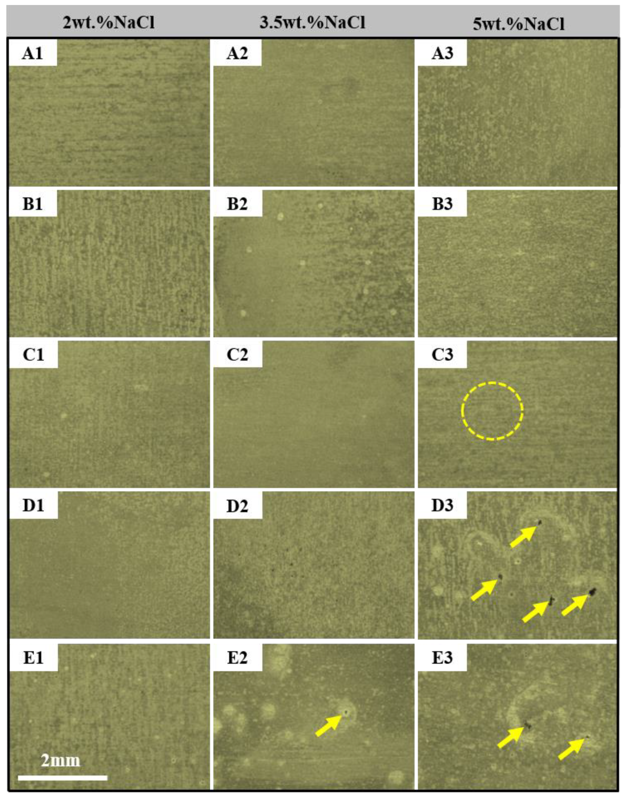
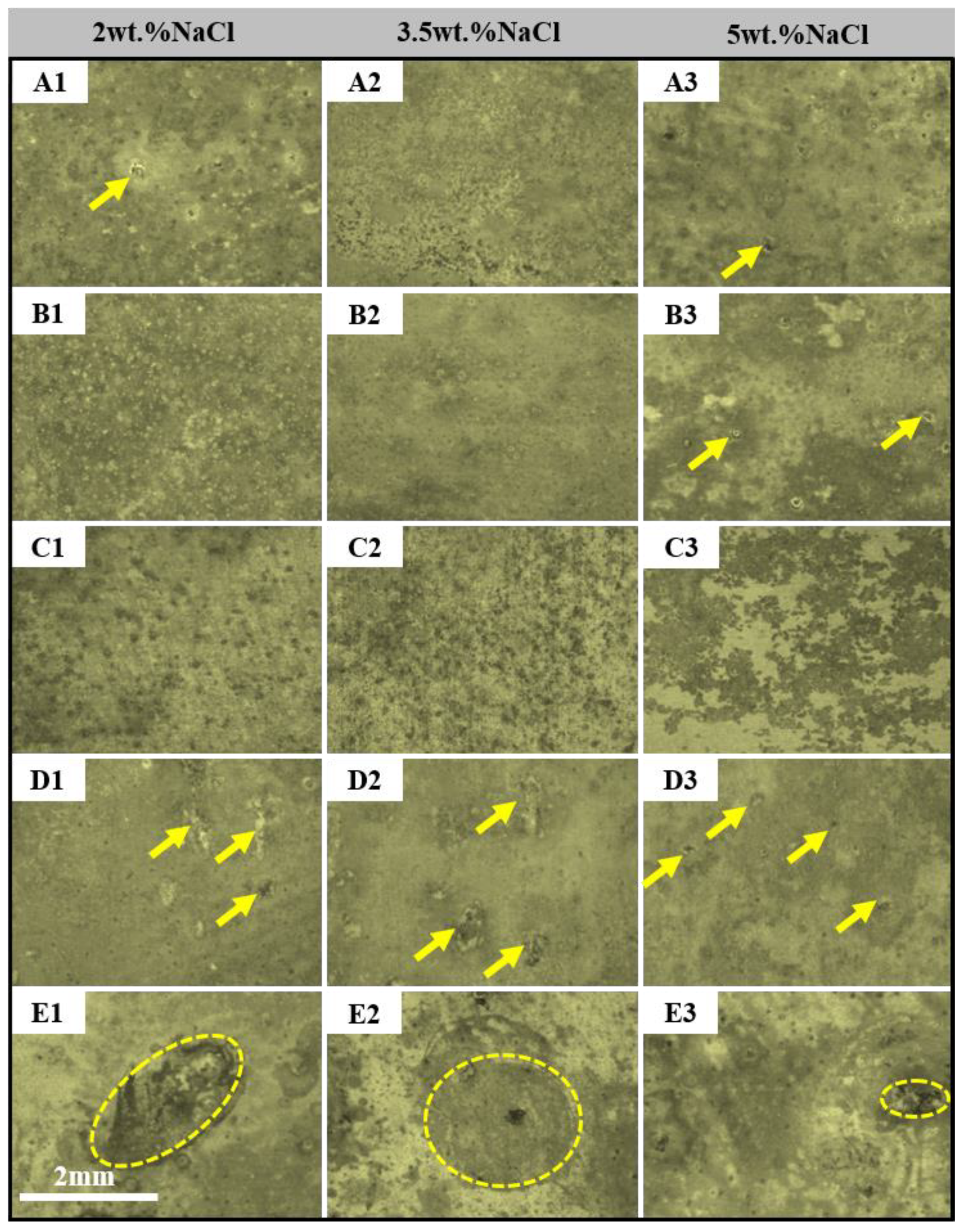
Figure 2(A1–3,B1–3,C1–3,D1–3,E1–3) shows the macroscopic morphology of the alloys after being respectively immersed in 2 wt.%, 3.5 wt.%, and 5 wt.% NaCl solution for 1 day. The corrosion morphologies of the 2A97-T3 and 2A97-T6 are roughly the same in Figure 2(A1–3,B1–3). A uniform gray-black corrosion product film is formed on the surface of the alloys. In addition, there is a modicum of white flocs in the solution and on their surface. Both surfaces of the 2A97-T3 and 2A97-T6 are coated with a uniform gray corrosion product film, and no visible pitting is observed in low concentration (2 wt.%) NaCl solution in Figure 2(A1,B1). On the contrary, a mass of circular tiny pits emerge on their surface, when the corrosion solution is 3.5 wt.% NaCl solution. The oxide film dissolves, due to the Cl being adsorbed on the active point of it [32,33]. Finally, the alloys are corroded in Figure 2(A2,B2). However, a large number of tiny pits are not observed on the surface of the alloys, and the corrosion morphology does not aggravate with the rise of NaCl concentration in the high-concentration (5 wt.%) NaCl solution in Figure 2(A3,B3). The reason is that the alloys are immersed in a high-concentration NaCl solution, which greatly advances the corrosion process of the alloy. Then the corrosion products are continuously generated and accumulated in the pits, which results in the corrosion pits being buried [34,35]. In the end, the alloy shows a relatively nice corrosion morphology on the surface.
Figure 2(C1–3) displays the macroscopic corrosion morphology of the 2024-T4 alloy after being immersed in three concentrations of NaCl solution for 1 day. The corrosion morphology of 2024-T4 is roughly the same in three concentrations of NaCl solution in Figure 2(C1–2). It indicates that the 2024-T4 has better corrosion resistance in low-concentration NaCl solution. The pits turn up on the surface of the 2024-T4, when the corrosion solution is a high-concentration (5 wt.%) NaCl solution, as shown by the circle in Figure 2(C3).
The corrosion morphologies of the 2060-T8 and 2099-T83 alloys are different from that of the 2A97-T3, 2A97-T6, and 2024-T4 in Figure 2(D1–3,E1–3). The gray corrosion product film emerges gully-shaped on the surface of the 2060-T8, which destroys the surface uniformity in low-concentration NaCl solution in Figure 2(D1), and the corrosion morphology of the 2099-T83 displays a large number of small pits on its surface in Figure 2(E1). When the concentration of NaCl solution surges to 3.5 wt.%, there is an abundance of tiny pits shown on the surface of the 2060-T8. However, the pits of the 2099-T83 are expanded into big corrosion pits, as shown by the arrow in Figure 2(D2,E2). In high-concentration NaCl solution, the corrosion morphologies of the 2060-T8 and 2099-T83 are further aggravated. Moreover, a large number of corrosion pits appear on the surface of the 2060-T8 in Figure 2(D3). Meanwhile, the increasing trend of the size of the pits of the 2099-T83 is also shown in Figure 2(E3).
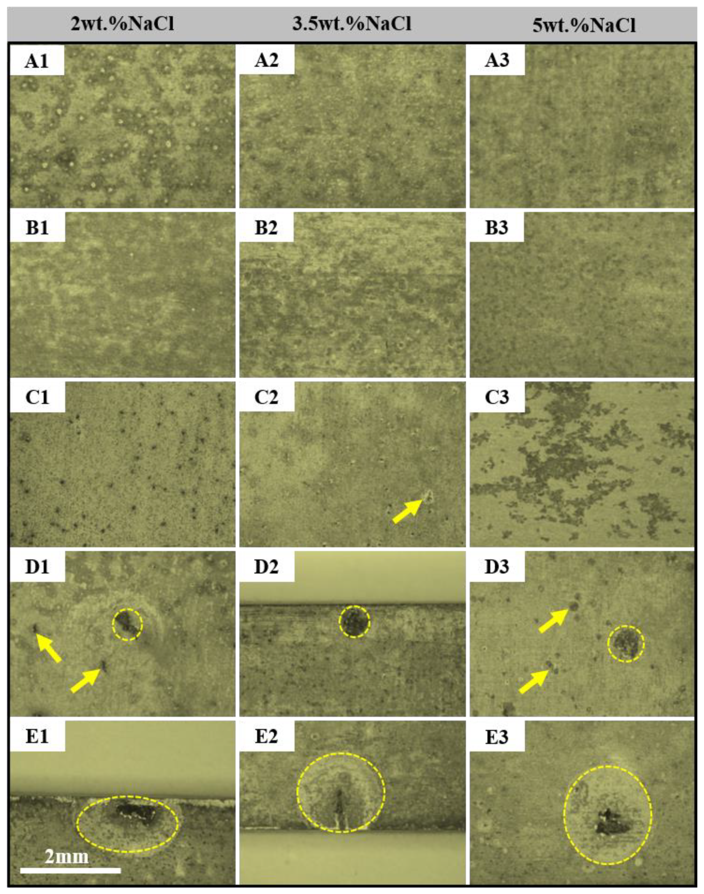
Figure 3 exhibits the macroscopic morphology of the alloys after respectively being soaked in three concentrations of NaCl solution for 7 days. There are a great deal of pits on the surface of the 2A97-T3, and the size of the pits gets larger in low-concentration NaCl solution in Figure 3(A1). However, the corrosion morphologies are completely different in 3.5 wt.% and 5 wt.% NaCl solutions. The pits are not observed on the surface of the alloys, and the corrosion morphology does not show a change with the increase in NaCl concentration and immersion time in Figure 3(A2–3). The dissolution of the oxide film is sped up by a significant amount of Cl, which accelerates the corrosion process of alloy in high-concentration NaCl solution. Further, the corrosion pits are buried, because of the corrosion products are continuously generated and accumulated in the pits. In the end, the number of pits of the alloy is relatively reduced on its surface. The corrosion morphology of the 2A97-T6 is similar to that of the 2A97-T3. However, the number of pits of the 2A97-T6 is more than that of the 2A97-T3 in Figure 3(B1,A1). The T1 phase is the primary precipitation phase of the 2A97-T6, it has a higher amount than other phases and a more uniform distribution [13]. When 2A97-T6 is submerged in NaCl solution, the preferential dissolution of the T1 phase is due to the selective dissolution of lithium, which results in the copper-containing residues enriching. Subsequently, the copper-rich residue serves as the cathodic relative to the Al matrix, which leads to the anodic dissolution of the peripheral Al matrix occurring [24,36,37,38]. Finally, the number and size of pits of the 2A97-T6 are both larger than those of the 2A97-T3.
Figure 3(C1–3) demonstrates the macroscopic corrosion morphology of the 2024-T4 alloys after being immersed in three concentrations of NaCl solution for 7 days. There are a large number of corrosion pits on its surface, and the oxide film of the surface has been destroyed in low-concentration NaCl solution in Figure 3(C1). Moreover, the corrosion degree is aggravated with the rise of the concentration of NaCl solution. The pits of the 2024-T4 are further expanded in 3.5 wt.% NaCl solution in Figure 3(C2). In 5 wt.% NaCl solution, the exfoliation corrosion occurs on the surface in Figure 3(C3). When the 2024-T4 alloys are immersed in NaCl solution, the boundary region is preferentially dissolved, which is between the intermetallic compound particles(Al2Cu, Al2CuMg, AlCuFeMn) and the Al matrix [39,40]. The microcell is formed by Mg-rich intermetallic compounds (Al2CuMg, etc.) and the Al matrix. Moreover, the intermetallic compounds are dissolved preferentially as an anode, because the potential of them are lower than that of the Al matrix [41]. The formation of the oxide film is affected by the alloying elements of intermetallic compounds and second-phase materials, which makes the oxide film presents an irregular porous morphology formed on the Al matrix [42]. This irregular oxide film facilitates Cl intrusion into the Al matrix, accordingly the corrosion rate of the alloy is accelerated.
The oxide film is gradually thinned and partially ruptured with the prolongation of immersion time, and macroscopically, there are many visible pits on their surface. Figure 3(D1–3,E1–3) exhibits the corrosion morphologies of the 2060-T8 and 2099-T83 alloys in three concentrations of NaCl, and the sizes of their partial pits range from 505 to 780 μm. Meanwhile, a lot of small pits turn up on their surface. The strong driving force for the preferential and selective dissolution of Al and Li in the grains, which is provided by the high copper content of the intermetallic compounds in 2099-T83. Moreover, the porous copper-rich residues act as an efficient cathode in the copper-rich phases (Al2Cu, Al2CuLi). Accordingly, the anodic dissolution of the nearby Al matrix occurs [25,37,38]. Additionally, the formation of the protective oxide film is hindered by the relatively high content of lithium and copper in the copper-rich phase [43,44,45,46]. In solution containing Cl, the copper-rich phases are preferentially dissolved in the Al matrix. Further, the anodic dissolution of the Al matrix comes up, owing to the electrochemical reaction between the copper-rich corrosion products and the Al matrix. Finally, it accelerates the formation of the pits [47,48].
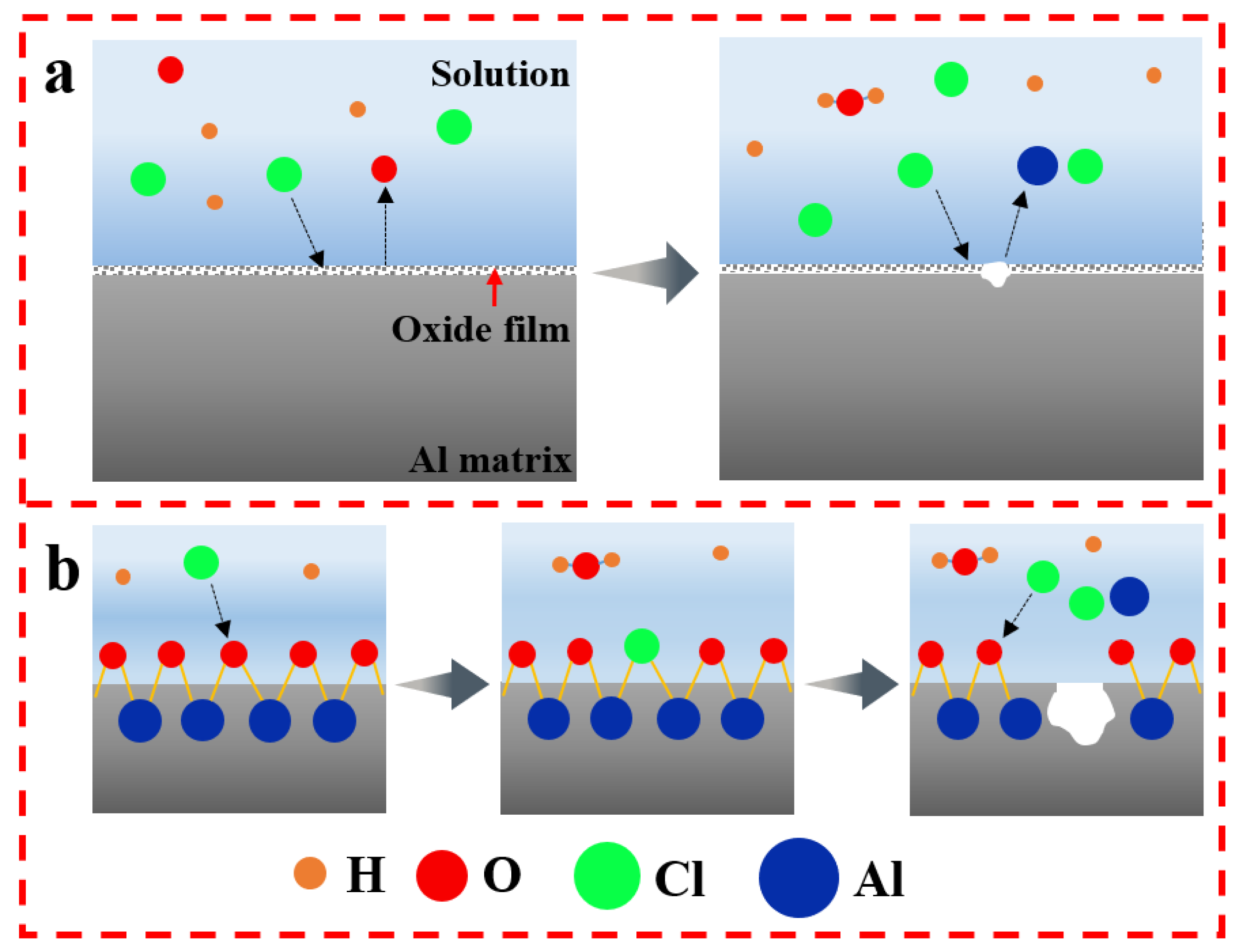
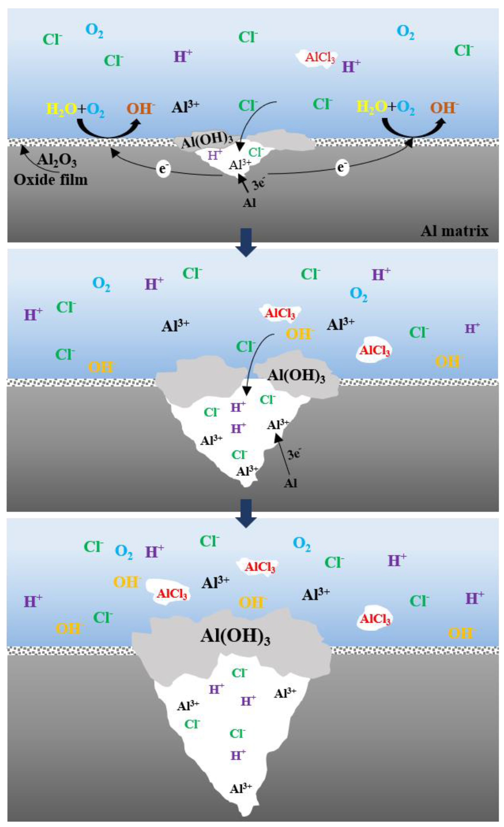
At the initial stage of immersion, the oxide film of the alloys is in a dynamic equilibrium state of dissolution and repair in NaCl solution, and the dynamic equilibrium state of dissolution and repair is destroyed as the concentration of Cl raise. Furthermore, the Cl is adsorbed in preference to O2 on the surface of Al alloy, and then the Cl is combined with the cations to form the soluble chloride in the oxide film, which causes the formation of the pits [33]. The pitting mechanism of the alloy is shown in Figure 4.
Figure 5 is the macroscopic morphologies of the alloys immersed in different concentrations of NaCl solution for 14 days. With the increase of immersion time, the extensive white flocs emerge on the surface of the alloys, and their coverage is gradually expanded. The oxide film of the 2A97-T6 and 2A97-T3 ruptures, and the number of pitting points on the surface of the specimen is also more concentrated in Figure 5(A1–3,B1–3). The number of pits of the 2024-T4 is further raising in Figure 5(C1–2), and the area of the exfoliation corrosion becomes larger and deeper in 5 wt.% NaCl solution in Figure 5(C3). The size of the pits of the 2060-T8 and 2099-T83 ranges from 510 to 910 μm in three concentrations of NaCl solution. Meanwhile, there are many pits on their surface in Figure 5(D1–3,E1–3).
Figure 6 presents the microscopic morphology of the alloys are immersed in different concentrations of NaCl solution for 14 days. The 2A97-T6 and 2A97-T3 are partially covered with a layer of corrosion products. Meanwhile, the network structure is the corrosion morphology of them, and the type of corrosion is intergranular corrosion in Figure 6(A1–3,B1–3). However, the corrosion products are less on the surface of 2A97-T6 and the crack width is larger, compared with 2A97-T3. The microscopic morphology of the 2024-T4 is similar to that of the 2A97-T6 and 2A97-T3. However, the corrosion products are the most on its surface, and the cracks are covered with corrosion products, so the observation is not clear in Figure 6(C1–2). What’s more, the corrosion behavior of the 2024-T4 is typified by typical layered exfoliation corrosion in 5 wt.% NaCl solution in Figure 6(C3). The annular corrosion products are formed in local areas on the surface of the 2060-T8 and 2099-T83, and the obvious cracks on the irregular block products in Figure 6(D1–3,E1–3).
When the time of immersion reaches 14 days, the corrosion morphology of the alloys is further aggravated. The 2A97-T3 has the best surface integrity of all, through a thorough analysis of the macroscopic and microscopic corrosion morphology. That is to say, its corrosion resistance performance of all is the best. What’s more, as shown in Figure 6, 2A97-T3 has the shallowest maximum corrosion pits on the surface, so the corrosion resistance performance of the 2A97-T6 is inferior to that of the 2A97-T3. The number of pits of the 2024-T4 is more than the 2A97-T3 and 2A97-T6, which illustrates that the corrosion resistance performance of the 2024-T4 is worse than that of theirs. The number and size of the pits of the 2060-T8 and 2099-T83 are further increased. In other words, their corrosion resistance performance is inferior to that of the 2A97-T3, 2A97-T6, and 2024-T4.
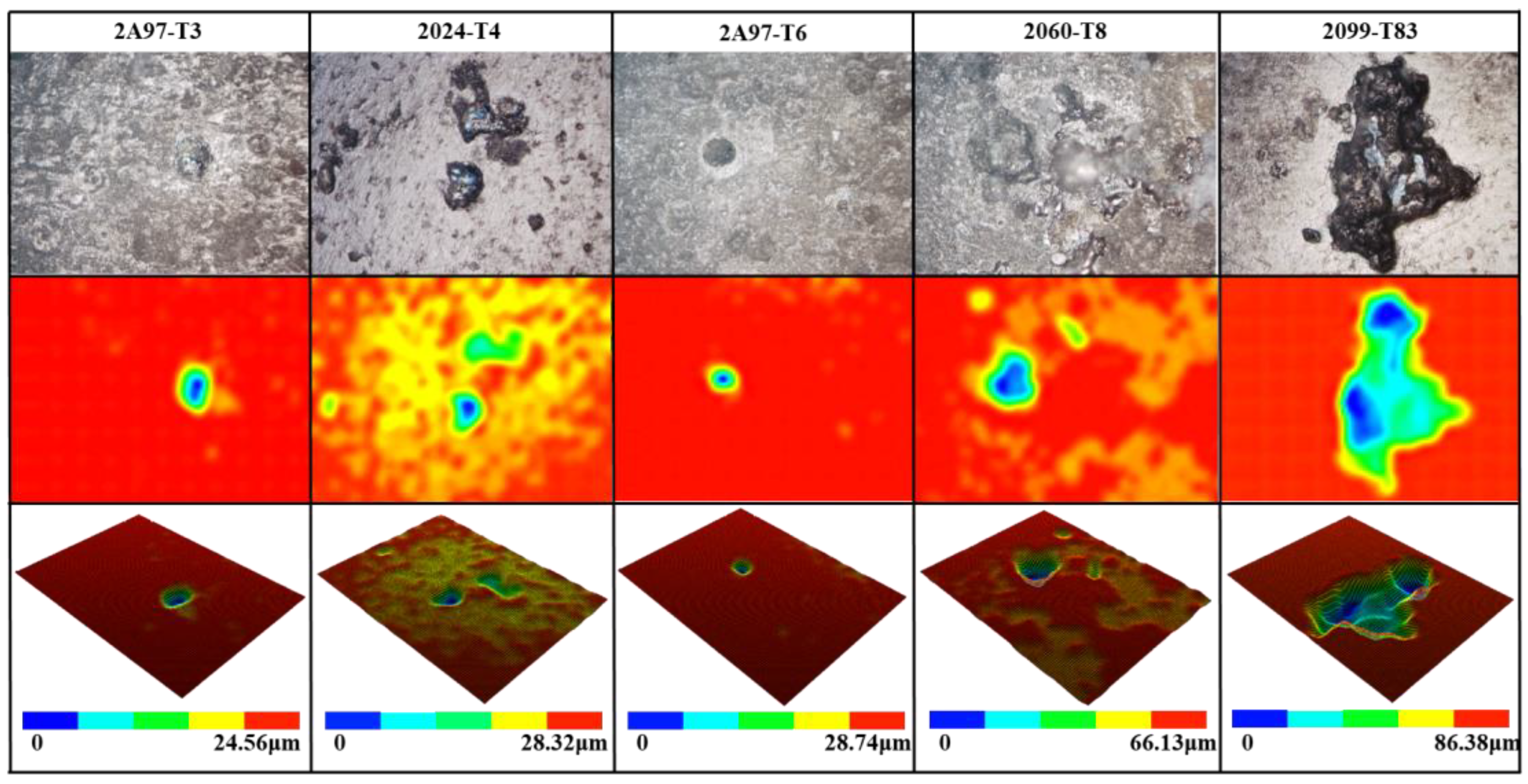
Figure 7 shows the corrosion surface and 3D morphology of the test material after 28 days of immersion in 3.5 wt.% NaCl solution as shown. The maximum corrosion pit depths of each specimen from the smallest to the largest: 2A97-T3 < 2024-T4 < 2A97-T6 < 2060-T8 < 2099-T83.
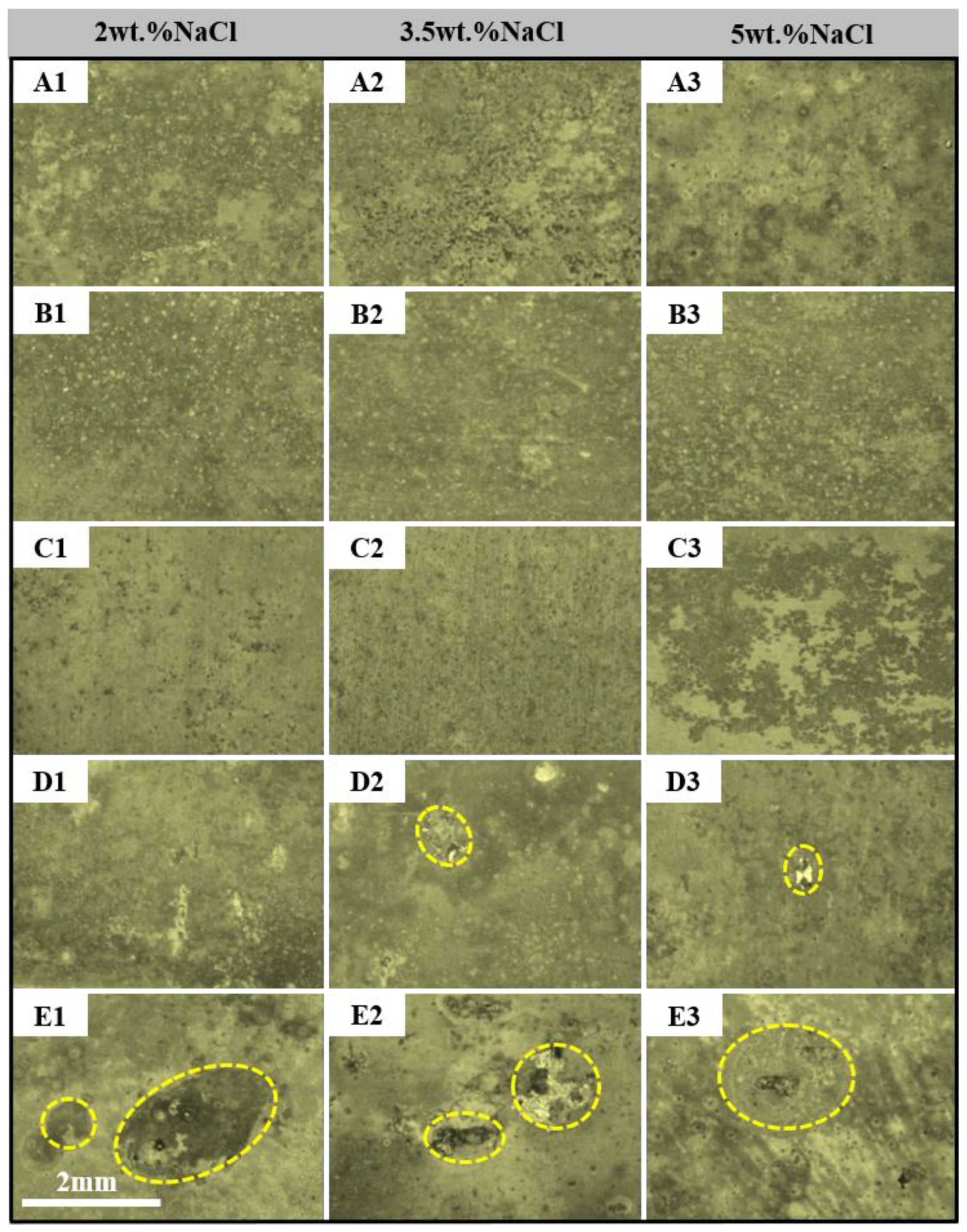
When the time of immersion reaches 21 days, the macroscopic corrosion morphology of each alloy is shown in Figure 8. There are more and more white flocs in the solution and on the surface of the alloy. Many bright pits appear on the surface of the 2A97-T3 and 2A97-T6 in low-concentration NaCl solution. Furthermore, the oxide film is destroyed, and the number of pits on the surface of the specimen is becoming more and more dense. Some pits expand to the surrounding area and are connected to the surrounding pitting pits with a smaller area in a local area, thereby expanding the corrosion area in Figure 8(A1,B1). However, the corrosion morphology of the alloys is completely different in 3.5 wt.% and 5 wt.% NaCl solutions. The pits are buried by corrosion products, and their outlines are shown on the surface in Figure 8(A2–3,B2–3). The 2024-T4 is characterized by the presence of numerous corrosion pits on its surface in 2 wt% and 3.5 wt% NaCl solutions. These pits are covered by corrosion products and unexposed the Al matrix in Figure 8(C1–2). Meanwhile, it still presents the exfoliation corrosion morphology in 5 wt.% NaCl solution, and the flake spalling is formed, due to the mutual penetration of the original local spalling area in Figure 8(C3). The pits of the 2060-T8 and 2099-T83 are covered by plenty of corrosion products in Figure 8(D1–3,E3). Furthermore, as the soaking time increases, the expansion of the pits is delayed or the pits are completely buried, owing to the corrosion products being continuously accumulated.
A continuous thick liquid film is formed on the surface of the alloy in the NaCl solution, which hinders the diffusion of oxygen in the solution, and the electrochemical corrosion process is mainly a cathodic reaction that is affected by the thick liquid film on the alloy surface [33,49,50]. Generally, the reactions of the anodic dissolution of Al alloy and the cathodic oxygen reduction are described by Equations (1) and (2):
Al 3 e Al 3 +
O 2 + 2 H 2 O + 4 e 4 OH
In addition, the concentration of Cl is a crucial characteristic that determines the local corrosion of the alloy. The Cl and O2 compete to adsorb on the oxide film, or the Cl is first adsorbed on the active sites of the Al matrix in the liquid film. Subsequently, the chemical reaction of the Cl with the metal cations occurs in the oxide film, which causes the oxide film is thinned and the Al matrix is disintegrated. Eventually, the pitting is formed.
In solution containing Cl, the reactions of anodic of Al alloy are described by Equations (3)–(5):
Al 3 + + H 2 O Al ( OH ) 2 + + H +
Al ( OH ) 2 + + Cl Al ( OH ) Cl +
Al ( OH ) Cl + + H 2 O Al ( OH ) 2 Cl + H +
The Reaction (4) is accelerated as the Cl concentration raises, so the intermediate reaction product Al(OH)2+ is continually consumed, which results in the anodic reaction of the Al matrix speeding up. However, the intermediate products of corrosion come into being at the junction, where the cathode and anode immediately contact in the solution. Moreover, the insoluble intermediate products can adhere to the alloy, which forms a thick and protective hydroxide layer immediately on the surface of the alloy. It also can cover a sizable portion of the metal surface, which hinders the further occurrence of corrosion. The expansion mechanism of the pits is shown in Figure 9.
When the immersion time reaches 28 days, the corrosion morphologies of alloys are shown in Figure 10. A significant number of brilliant pits are shown on the surface of the 2A97-T3 in low-concentration NaCl solution in Figure 10(A1). However, the bright pits decrease as the concentration of NaCl solution increases. Instead, the majority of the pits are covered by the corrosion products in Figure 10(A2–3). The corrosion process is accelerated as the concentration of NaCl solution rises. Moreover, the corrosion products are produced massively, and as a result, they are accumulated and covered around the pits. Eventually, the process of corrosion is impeded. The corrosion morphology of the 2A97-T6 is similar to that of the 2A97-T3 in low-concentration NaCl solution, and a large number of bright pits emerge on its surface in Figure 10(B1). However, it is distinct from that of the 2A97-T3, there are still brilliant pits on its surface as the concentration of NaCl solution increases. Further, the number of the pits drops, but their size increases in Figure 10(B2–3). There is still a large number of pits on the surface of the 2024-T4 in 2 wt.% and 3.5 wt.% NaCl solutions in Figure 10(C1–2), and some pits are covered by corrosion products, which hinders the further occurrence of corrosion, whereas the range of exfoliation corrosion morphology is further expanded in 5 wt.% NaCl solution in Figure 10(C3). The pits of the 2060-T8 and 2099-T83 are covered by plenty of corrosion products, which leads to retarding or stopping the expansion of the pits. Furthermore, the corrosion products that cover some pits prevent them from being seen. However, the size of the pits of the 2099-T83 is significantly larger than that of the 2060-T8 under the same conditions in Figure 10(D1–3,E1–3). It can be seen that the corrosion resistance of the 2099-T83 is the worst of all, followed by the 2060-T8.
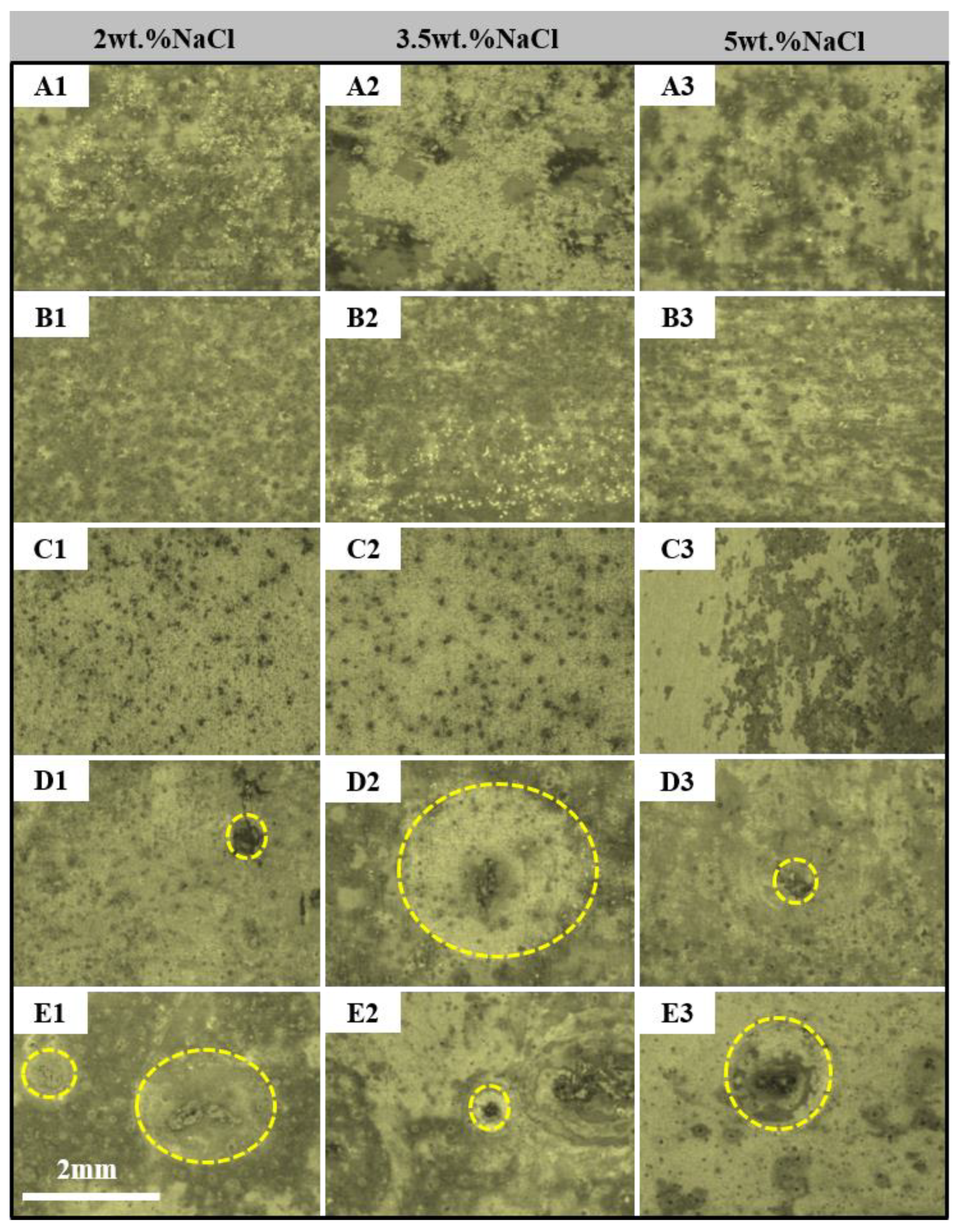
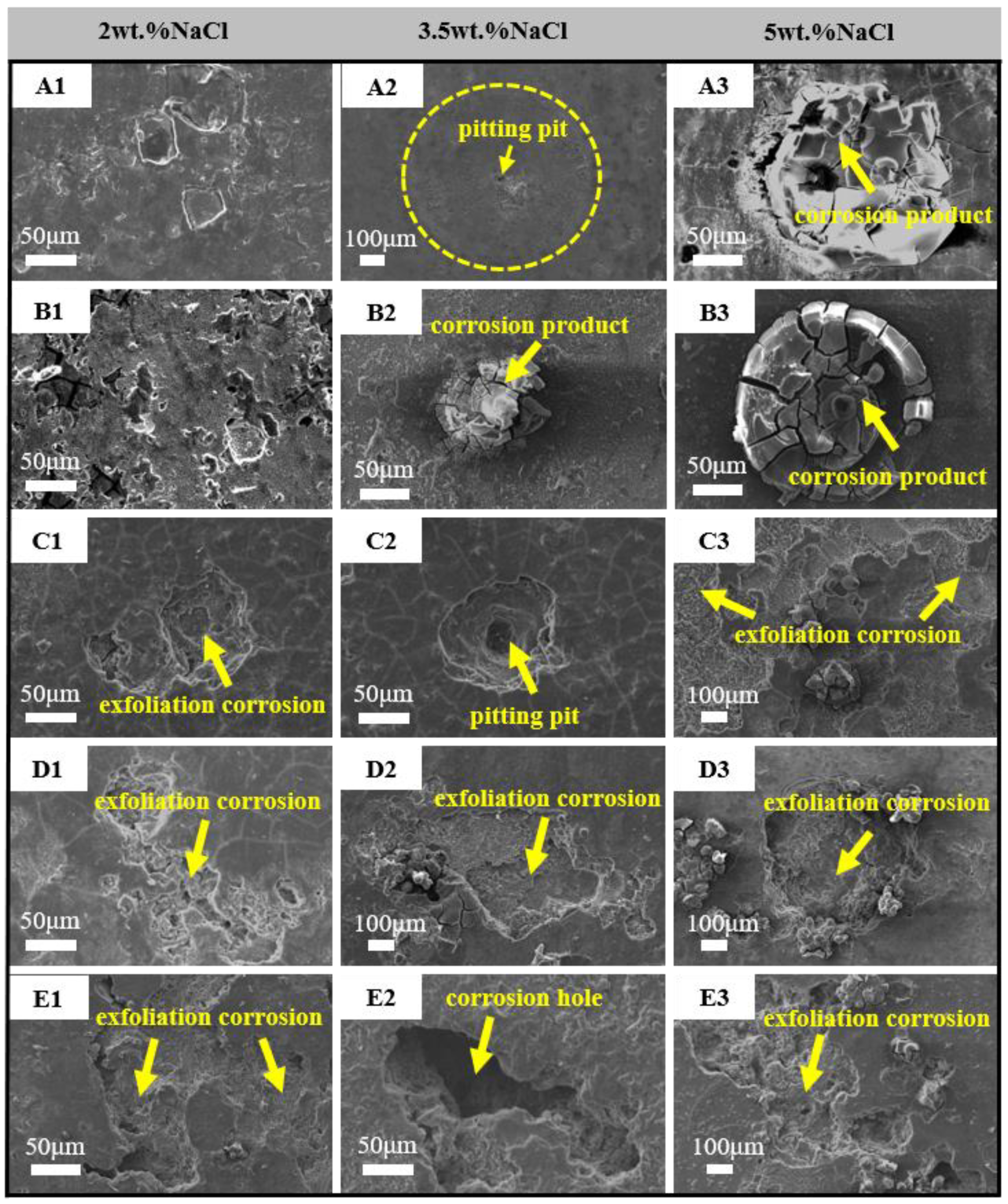
Figure 11 is the microscopic morphology of the alloys immersed in different concentrations of NaCl solution for 28 days. The corrosion products on the surface of the 2A97-T3 are slightly peeled off in bulk in the low-concentration NaCl solution in Figure 11(A1). The typical pitting pits and corrosion ring are observed on the surface of the 2A97-T3 in 3.5 wt.% NaCl solution in Figure 11(A2). In high-pconcentration NaCl solution, the cellular corrosion product is formed above the pits of the 2A97-T3 in Figure 11(A3). The corrosion morphology of the 2A97-T6 is similar to that of the 2A97-T3. Specifically, the peeling area of the corrosion products of the 2A97-T6 is enlarged, and the degree is also intensified in the low-concentration NaCl solution in Figure 11(B1). The circular corrosion product is formed above the pits of the 2A97-T6 in local areas in 3.5 wt.% and 5 wt.% NaCl solutions in Figure 11(B2,B3), and the difference between the two is that the area of circular corrosion products is significantly larger in 5 wt.% NaCl solution. The network fractures on the surface of the 2024-T4 are more visible, and the corrosion pits have an obvious layered structure. With the rise of NaCl concentration, the number of pits also increases in Figure 11(C1–2), and the local corrosion products on the surface of the 2024-T4 fall off on a large scale in Figure 11(C3). The microstructure of the 2060-T8 illustrates that the pits grow in the direction of depth and width, and the obvious cellular corrosion products are formed in local areas in Figure 11(D1–3). The corrosion morphology of the 2099-T83 is similar to that of the 2060-T8 in Figure 11(E1–3). The pits of the 2099-T83 are significantly larger than the 2060-T8 regardless of the width and depth.

4. Conclusions

(1)
The pitting corrosion and minor block erosion morphologies are visible on the 2A97 (T3, T6). The corrosion morphology of 2024-T4 is severe localized exfoliation corrosion. Furthermore, there are many deep pits and large areas of exfoliation corrosion on the corrosion surface of the 2060-T8 and 2099-T83.
(2)
The corrosion morphology of the sample and the maximum depth of the etching pit are analyzed. It is concluded that the corrosion resistance of each specimen is from strong to weak: 2A97-T3 > 2A97-T6 > 2024-T4 > 2060-T8 > 2099-T83.
(3)
The dissolution and rupture of the oxide film of the alloys are accelerated with the increase in NaCl solution concentration and the extension of immersion time, so the local corrosion occurs. However, the intermediate products adhere to the alloy, which retards the process of corrosion.

Author Contributions

Conceptualization, P.Z.; methodology, P.Z.; software, X.Z.; validation, P.Z. and X.Z.; formal analysis, Z.W.; investigation, P.Z. and X.Z.; resources, Z.W. and P.Z.; data curation, S.R.; writing—original draft preparation, X.Z.; writing—review and editing, P.Z.; visualization, X.Z.; supervision, S.R.; project administration, P.Z.; funding acquisition, Z.W., P.Z. and S.R. All authors have read and agreed to the published version of the manuscript.

Funding

This research was funded by Postgraduate Research & Practice Innovation Program of Jiangsu Province grant number KYCX21_0231 And Key Projects of Scientific Research in Colleges and Universities of Anhui Provincial Department of Education grant number KJ2021A0367, General Project of Natural Science Foundation of Anhui Provincial Department of Science and Technology grant number 908085ME148.

Institutional Review Board Statement

Not applicable.

Informed Consent Statement

Not applicable.

Data Availability Statement

Not applicable.

Conflicts of Interest

The authors declare no conflict of interest.

References

  1. Rioja, R.J. Fabrication methods to manufacture isotropic Al-Li alloys and products for space and aerospace applications. Mater. Sci. Eng. A 1998, 257, 100–107. [Google Scholar] [CrossRef]
  2. Khokhlatova, L.B.; Kolobnev, N.I.; Oglodkov, M.S.; Mikhaylov, E.D. Aluminum-lithium alloys for aircraft building. Metallurgist 2012, 56, 336–341. [Google Scholar] [CrossRef]
  3. Rioja, R.J.; Liu, J. The Evolution of Al-Li Base Products for Aerospace and Space Applications. Metall. Mater. Trans. A 2012, 43, 3325–3337. [Google Scholar] [CrossRef]
  4. Abd El-Aty, A.; Xu, Y.; Guo, X.; Zhang, S.-H.; Ma, Y.; Chen, D. Strengthening mechanisms, deformation behavior, and anisotropic mechanical properties of Al-Li alloys: A review. J. Adv. Res. 2018, 10, 49–67. [Google Scholar] [CrossRef] [PubMed]
  5. Lin, Y.; Lu, C.; Wei, C.; Zheng, Z. Effect of aging treatment on microstructures, tensile properties and intergranular corrosion behavior of Al–Cu–Li alloy. Mater. Charact. 2018, 141, 163–168. [Google Scholar] [CrossRef]
  6. Jia, L.; Ren, X.; Hou, H.; Zhang, Y. Microstructural evolution and superplastic deformation mechanisms of as-rolled 2A97 alloy at low-temperature. Mater. Sci. Eng. A 2019, 759, 19–29. [Google Scholar] [CrossRef]
  7. Gurao, N.P.; Adesola, A.O.; Odeshi, A.G.; Szpunar, J.A. On the evolution of heterogeneous microstructure and microtexture in impacted aluminum–lithium alloy. J. Alloys Compd. 2013, 578, 183–187. [Google Scholar] [CrossRef]
  8. Paz Martínez-Viademonte, M.; Abrahami, S.T.; Hack, T.; Burchardt, M.; Terryn, H. A Review on Anodizing of Aerospace Aluminum Alloys for Corrosion Protection. Coatings 2020, 10, 1106. [Google Scholar] [CrossRef]
  9. Dursun, T.; Soutis, C. Recent developments in advanced aircraft aluminium alloys. Mater. Des. 2014, 56, 862–871. [Google Scholar] [CrossRef]
  10. Zhang, P.; Chen, M.-H.; Chen, W.; Zhang, S.-H.; Xu, Y. Mechanisms and microstructures of 2A97 Al-Li alloy under the hot forming with synchronous quenching process. Microsc. Res. Tech. 2021, 84, 358–367. [Google Scholar] [CrossRef]
  11. Yu, J.; Lu, Z.; Xiong, Y.C.; Li, G.A.; Feng, Z.H. Effect of Intermediate Thermomechanical Treatment on Microstructure and Mechanical Properties of 2A97 Al-Li Alloy. J. Mater. Eng. 2021, 49, 130–136. [Google Scholar] [CrossRef]
  12. Chen, H.; Fu, L.; Liang, P. Microstructure, texture and mechanical properties of friction stir welded butt joints of 2A97 Al Li alloy ultra-thin sheets. J. Alloys Compd. 2017, 692, 155–169. [Google Scholar] [CrossRef]
  13. Zhang, P.; Chen, M.-H. Effect of Preliminary Tension and Conditions of Artificial Aging on the Microstructure and Properties of Al–Li Alloy 2A97-T3. Met. Sci. Heat Treat. 2021, 63, 47–52. [Google Scholar] [CrossRef]
  14. Wang, K.P.; Alkire, R.C. Local Chemistry and Growth of Single Corrosion Pits in Aluminum. J. Electrochem. Soc. 1990, 137, 3010–3015. [Google Scholar] [CrossRef]
  15. Sinyavskii, V.S. Pitting and Stress Corrosions of Aluminum Alloys; Correlation between Them. Prot. Met. 2001, 37, 521–530. [Google Scholar] [CrossRef]
  16. Del Silva Campos, M.R.; Blawert, C.; Scharnagl, N.; Störmer, M.; Zheludkevich, M.L. Cathodic Protection of Mild Steel Using Aluminium-Based Alloys. Materials 2022, 15, 1301. [Google Scholar] [CrossRef]
  17. Liu, Y.; Cao, H.; Chen, S.; Wang, D. Ag Nanoparticle-Loaded Hierarchical Superamphiphobic Surface on an Al Substrate with Enhanced Anticorrosion and Antibacterial Properties. J. Phys. Chem. C 2015, 119, 25449–25456. [Google Scholar] [CrossRef]
  18. Klumpp, R.E.; Donatus, U.; Araujo, J.V.S.; Redígolo, M.M.; Machado, C.d.S.C.; Costa, I. The Effect of Acid Pickling on the Corrosion Behavior of a Cerium Conversion-Coated AA2198-T851 Al-Cu-Li Alloy. J. Mater. Eng. Perform. 2020, 29, 167–174. [Google Scholar] [CrossRef]
  19. Ma, Y.; Zhou, X.; Thompson, G.E.; Zhang, X.; Luo, C.; Curioni, M.; Liu, H. Microstructural Modification Arising from Alkaline Etching and Its Effect on Anodizing Behavior of Al-Li-Cu Alloy. J. Electrochem. Soc. 2013, 160, C111–C118. [Google Scholar] [CrossRef]
  20. Proton, V.; Alexis, J.; Andrieu, E.; Delfosse, J.; Deschamps, A.; de Geuser, F.; Lafont, M.-C.; Blanc, C. The influence of artificial ageing on the corrosion behaviour of a 2050 aluminium–copper–lithium alloy. Corros. Sci. 2014, 80, 494–502. [Google Scholar] [CrossRef]
  21. Na, J.; Li, J.; Zheng, Z.; Wei, X.; Li, Y. Effect of aging on mechanical properties and localized corrosion behaviors of Al-Cu-Li alloy. Trans. Nonferr. Met. Soc. China 2005, 15, 23–29. [Google Scholar]
  22. Liang, W.; Pan, Q.; He, Y.; Li, Y.; Zhou, Y.; Lu, C. Effect of aging on the mechanical properties and corrosion susceptibility of an Al-Cu-Li-Zr alloy containing Sc. Rare Met. 2008, 27, 146–152. [Google Scholar] [CrossRef]
  23. Zhang, X.; Zhou, X.; Hashimoto, T.; Lindsay, J.; Ciuca, O.; Luo, C.; Sun, Z.; Tang, Z. The influence of grain structure on the corrosion behaviour of 2A97-T3 Al-Cu-Li alloy. Corros. Sci. 2017, 116, 14–21. [Google Scholar] [CrossRef]
  24. Zhang, X.; Zhou, X.; Hashimoto, T.; Liu, B.; Luo, C.; Sun, Z.; Tang, Z.; Lu, F.; Ma, Y. Corrosion behaviour of 2A97-T6 Al-Cu-Li alloy: The influence of non-uniform precipitation. Corros. Sci. 2018, 132, 1–8. [Google Scholar] [CrossRef]
  25. Ma, Y.; Zhou, X.; Huang, W.; Thompson, G.E.; Zhang, X.; Luo, C.; Sun, Z. Localized corrosion in AA2099-T83 aluminum–lithium alloy: The role of intermetallic particles. Mater. Chem. Phys. 2015, 161, 201–210. [Google Scholar] [CrossRef]
  26. Luo, C.; Gao, M.; Sun, Z.; Zhang, X.; Tang, Z.; Zhou, X. FIB-SEM investigation on corrosion propagation of aluminium–lithium alloy in sodium chloride solution. Corros. Eng. Sci. Technol. 2015, 50, 390–396. [Google Scholar] [CrossRef]
  27. Xu, X.; Hao, M.; Chen, J.; He, W.; Li, G.; Li, K.; Jiao, C.; Zhong, X.L.; Moore, K.L.; Burnett, T.L.; et al. Role of constituent intermetallic phases and precipitates in initiation and propagation of intergranular corrosion of an Al-Li-Cu-Mg alloy. Corros. Sci. 2022, 201, 110294. [Google Scholar] [CrossRef]
  28. Zhang, X.; Liu, B.; Zhou, X.; Wang, J.; Hashimoto, T.; Luo, C.; Sun, Z.; Tang, Z.; Lu, F. Laser welding introduced segregation and its influence on the corrosion behaviour of Al-Cu-Li alloy. Corros. Sci. 2018, 135, 177–191. [Google Scholar] [CrossRef]
  29. Zhang, X.; Lv, Y.; Zhou, X.; Hashimoto, T.; Ma, Y. Corrosion behaviour of 2A97-T8 Al-Cu-Li alloy extrusion. J. Alloys Compd. 2022, 898, 162872. [Google Scholar] [CrossRef]
  30. Zhang, X.; Liu, B.; Zhao, X.; Wang, J.; Luo, C.; Sun, Z.; Tang, Z.; Lu, F. Corrosion behavior of friction stir welded 2A97 Al-Cu-Li alloy. Corrosion 2017, 73, 988–997. [Google Scholar] [CrossRef]
  31. Zhang, X.; Zhou, X.; Ma, Y.; Thompson, G.E.; Luo, C.; Sun, Z.; Tang, Z. The propagation of localized corrosion in Al-Cu-Li alloy. Surf. Interface Anal. 2016, 48, 745–749. [Google Scholar] [CrossRef]
  32. Boinovich, L.B.; Emelyanenko, A.M.; Modestov, A.D.; Domantovsky, A.G.; Shiryaev, A.A.; Emelyanenko, K.A.; Dvoretskaya, O.V.; Ganne, A.A. Corrosion behavior of superhydrophobic aluminum alloy in concentrated potassium halide solutions: When the specific anion effect is manifested. Corros. Sci. 2016, 112, 517–527. [Google Scholar] [CrossRef]
  33. Szklarska-Smialowska, Z. Pitting corrosion of aluminum. Corros. Sci. 1999, 41, 1743–1767. [Google Scholar] [CrossRef]
  34. Zaid, B.; Saidi, D.; Benzaid, A.; Hadji, S. Effects of pH and chloride concentration on pitting corrosion of AA6061 aluminum alloy. Corros. Sci. 2008, 50, 1841–1847. [Google Scholar] [CrossRef]
  35. Soltis, J. Passivity breakdown, pit initiation and propagation of pits in metallic materials—Review. Corros. Sci. 2015, 90, 5–22. [Google Scholar] [CrossRef]
  36. Li, J.F.; Li, C.X.; Peng, Z.W.; Chen, W.J.; Zheng, Z.Q. Corrosion mechanism associated with T1 and T2 precipitates of Al–Cu–Li alloys in NaCl solution. J. Alloys Compd. 2008, 460, 688–693. [Google Scholar] [CrossRef]
  37. Liu, Y.; Colin, F.; Skeldon, P.; Thompson, G.E.; Zhou, X.; Habazaki, H.; Shimizu, K. Enrichment factors for copper in aluminium alloys following chemical and electrochemical surface treatments. Corros. Sci. 2003, 45, 1539–1544. [Google Scholar] [CrossRef]
  38. Hashimoto, T.; Zhou, X.; Skeldon, P.; Thompson, G.E. Structure of the Copper–Enriched Layer Introduced by Anodic Oxidation of Copper-Containing Aluminium Alloy. Electrochim. Acta 2015, 179, 394–401. [Google Scholar] [CrossRef]
  39. Davoodi, A.; Pan, J.; Leygraf, C.; Norgren, S. Probing of local dissolution of Al-alloys in chloride solutions by AFM and SECM. Appl. Surf. Sci. 2006, 252, 5499–5503. [Google Scholar] [CrossRef]
  40. Ryl, J.; Wysocka, J.; Jarzynka, M.; Zielinski, A.; Orlikowski, J.; Darowicki, K. Effect of native air-formed oxidation on the corrosion behavior of AA 7075 aluminum alloys. Corros. Sci. 2014, 87, 150–155. [Google Scholar] [CrossRef]
  41. Al-Moubaraki, A.H.; Al-Rushud, H.H. The Red Sea as a Corrosive Environment: Corrosion Rates and Corrosion Mechanism of Aluminum Alloys 7075, 2024, and 6061. Int. J. Corros. 2018, 2018, 2381287. [Google Scholar] [CrossRef]
  42. Curioni, M.; Saenz de Miera, M.; Skeldon, P.; Thompson, G.E.; Ferguson, J. Macroscopic and Local Filming Behavior of AA2024 T3 Aluminum Alloy during Anodizing in Sulfuric Acid Electrolyte. J. Electrochem. Soc. 2008, 155, C387. [Google Scholar] [CrossRef]
  43. Ma, Y.; Zhou, X.; Thompson, G.E.; Curioni, M.; Zhong, X.; Koroleva, E.; Skeldon, P.; Thomson, P.; Fowles, M. Discontinuities in the porous anodic film formed on AA2099-T8 aluminium alloy. Corros. Sci. 2011, 53, 4141–4151. [Google Scholar] [CrossRef]
  44. Crossland, A.C.; Habazaki, H.; Shimizu, K.; Skeldon, P.; Thompson, G.E.; Wood, G.C.; Zhou, X.; Smith, C. Residual flaws due to formation of oxygen bubbles in anodic alumina. Corros. Sci. 1999, 41, 1945–1954. [Google Scholar] [CrossRef]
  45. Buchheit, R.G. A Compilation of Corrosion Potentials Reported for Intermetallic Phases in Aluminum Alloys. J. Electrochem. Soc. 1995, 142, 3994–3996. [Google Scholar] [CrossRef]
  46. Birbilis, N.; Buchheit, R.G. Electrochemical Characteristics of Intermetallic Phases in Aluminum Alloys: An Experimental Survey and Discussion. J. Electrochem. Soc. 2005, 152, 140–151. [Google Scholar] [CrossRef] [Green Version]
  47. Karthik, D.; Jiang, J.; Hu, Y.; Yao, Z. Effect of multiple laser shock peening on microstructure, crystallographic texture and pitting corrosion of Aluminum-Lithium alloy 2060-T8. Surf. Coat. Technol. 2021, 421, 127354. [Google Scholar] [CrossRef]
  48. Han, B.; Chen, Y.; Tao, W.; Li, H.; Li, L. Microstructural evolution and interfacial crack corrosion behavior of double-sided laser beam welded 2060/2099 Al-Li alloys T-joints. Mater. Des. 2017, 135, 353–365. [Google Scholar] [CrossRef]
  49. Newman, R. Pitting Corrosion of Metals. Electrochem. Soc. Interface 2010, 19, 33–38. [Google Scholar] [CrossRef] [Green Version]
  50. Ezuber, H.; El-Houd, A.; El-Shawesh, F. A study on the corrosion behavior of aluminum alloys in seawater. Mater. Des. 2008, 29, 801–805. [Google Scholar] [CrossRef]
Figure 1. The macroscopic morphology of the sample before soaking.
Coatings 12 01899 g001
Figure 2. The macroscopic morphology of the alloys immersed in different concentrations of NaCl solution for 1 day ((A1A3): 2A97-T3; (B1B3): 2A97-T6; (C1C3): 2024-T4; (D1D3): 2060-T8; (E1E3): 2099-T83).
Coatings 12 01899 g002
Figure 3. The macroscopic morphology of specimens immersed in different concentrations of NaCl solution for 7 days ((A1A3): 2A97-T3; (B1B3): 2A97-T6; (C1C3): 2024-T4; (D1D3): 2060-T8; (E1E3): 2099-T83).
Coatings 12 01899 g003
Figure 4. The schematic diagram (a) and mechanism diagram (b) of the Al alloy pitting corrosion.
Coatings 12 01899 g004
Figure 5. The macroscopic morphology of specimens immersed in different concentrations of NaCl solution for 14 days ((A1A3): 2A97-T3; (B1B3): 2A97-T6; (C1C3): 2024-T4; (D1D3): 2060-T8; (E1E3): 2099-T83).
Coatings 12 01899 g005
Figure 6. The microscopic morphology of specimens immersed in different concentrations of NaCl solution for 14 days ((A1A3): 2A97-T3; (B1B3): 2A97-T6; (C1C3): 2024-T4; (D1D3): 2060-T8; (E1E3): 2099-T83).
Coatings 12 01899 g006
Figure 7. The corroded surface and 3D morphology of the test material after soaking in 3.5 wt.% NaCl solution for 28 days.
Coatings 12 01899 g007
Figure 8. The macroscopic topography of specimens soaked in different concentrations of NaCl solution for 21 days ((A1A3): 2A97-T3; (B1B3): 2A97-T6; (C1C3): 2024-T4; (D1D3): 2060-T8; (E1E3): 2099-T83).
Coatings 12 01899 g008
Figure 9. The expansion mechanism of the pits.
Coatings 12 01899 g009
Figure 10. The macroscopic morphology of specimens immersed in different concentrations of NaCl solution for 28 days ((A1A3): 2A97-T3; (B1B3): 2A97-T6; (C1C3): 2024-T4; (D1D3): 2060-T8; (E1E3): 2099-T83).
Coatings 12 01899 g010
Figure 11. The microscopic morphology of specimens immersed in different concentrations of NaCl solution for 28 days ((A1A3): 2A97-T3; (B1B3): 2A97-T6; (C1C3): 2024-T4; (D1D3): 2060-T8; (E1E3): 2099-T83).
Coatings 12 01899 g011
Table 1. The chemical constituents of the alloys (wt.%).
AlloyCuLiZnMgMnZrFeAgSiTiAl
2A973.551.310.50.370.310.110.044<0.03<0.030.024Bal.
2060-T83.810.80.3110.7930.2690.1690.020.5270.070.0281Bal.
2099-T832.221.870.5810.3520.2760.1220.023-0.0480.026Bal.
2024-T46.12-0.0861.151.24-1.17-0.160.022Bal.
Publisher’s Note: MDPI stays neutral with regard to jurisdictional claims in published maps and institutional affiliations.