Article

Microstructures, Composition and Tribological Behavior of TiCrN/MoS2–TiCr Coatings Deposited by Magnetron Sputtering

College of Mechanical Engineering, Guizhou University, Guiyang 550025, China
*
Author to whom correspondence should be addressed.
Coatings 2022, 12(12), 1844; https://doi.org/10.3390/coatings12121844
Submission received: 24 October 2022 / Revised: 23 November 2022 / Accepted: 26 November 2022 / Published: 29 November 2022
(This article belongs to the Special Issue Recent Advances in Functional Surfaces and Interfaces)

Abstract

:
To enhance the tribological performance of the conventional TiCrN coating, the MoS2–TiCr coatings are deposited onto the TiCrN layer by magnetron sputtering. In general, the MoS2 is implemented to enhance the friction reduction performance of the TiCrN coating, while the Ti and Cr are doped to increase the density of the structure and prevent MoS2 from oxidizing. The results reveal that with an increase in the content of Ti and Cr in the MoS2–TiCr top layer, the hardness and the coating–substrate adhesion force of the composite coating increase, respectively, due to the compact top layer. Further, the optimized Ti and Cr doping in the MoS2 top layer greatly enhances the tribological properties of the TiCrN/MoS2–TiCr composite coating with a friction coefficient as low as 0.06 and the wear rate is only 6% of the TiCrN coating. The main reason for the excellent tribological properties of the TiCrN/MoS2–TiCr composite coating is probably due to the recrystallization of the MoS2 in the process of wear.

1. Introduction

Tools, molds, auto parts, and bolts tend to suffer from severe surface wear during work due to their soft surface texture and high friction coefficients, resulting in shorter service life. To improve the wear resistance of their surfaces, many researchers are trying to deposit hard coatings onto the surface of these parts [1,2,3,4]. Nitride coating is a kind of wear-resistant hard coating, usually composed of a mixed bond of the covalent bond and metal bond, so it has the characteristics of a high melting point, high hardness, and not easily corroded by chemical gases or liquids [5,6]. It was reported that the hardness of these coatings can reach up to 36 GPa [7]. The TiCrN coating is one of many nitride coatings which has been widely deposited on surfaces in recent years to increase wear resistance [8]. However, the friction coefficient of the TiCrN coating is high, and a large amount of frictional heat and wear rate will be generated under the condition of high speed and heavy load. In order to reduce the friction coefficient and wear rate of the nitride hard coating, soft lubricating coatings, such as MoS2 and WS2, are deposited on its surface. Li et al. [9] prepared a TiSiN–WS2 coating on the surface of WC/TiC/Co cemented carbide. Compared to a single TiSiN coating, the tribological performance of the hard-lubricating coating was greatly improved. Lukaszkowicz et al. [10] deposited a CrAlSiN + MoS2 coating on an X40CrMoV5-1 steel substrate. The composite lubricating coating showed better wear resistance and a lower friction coefficient compared to the substrate. To improve the tribological properties of an AlCrN coating, Lu et al. [11] deposited a MoS2/PTFE composite layer on its surface and the AlCrN-MoS2/PTFE coating effectively reduced the friction coefficient and increased the coating–substrate adhesion strength by 15%.
Depositing a pure soft lubricating coating on the surface of the nitride coating, the friction coefficient and wear rate have been reduced to a certain extent. However, the load-bearing capacity of the soft lubricating coating is low, which is not suitable for applications in extremely heavy-duty environments. In order to improve the mechanical properties and friction and wear properties of the top coating, doping transition metal elements onto the soft lubricating layer is an extremely effective way. It was reported that doping Ti in the MoS2 coating not only improves its hardness and compactness, but also enhances the growth of MoS2 (002) crystal planes, and the (002) crystal plane of MoS2 has a positive effect on lubricity and corrosion resistance [12,13,14]. Furthermore, doping with Cr can improve the heat resistance and oxidation resistance of the MoS2 coatings [15,16].
In our work, magnetron sputtering is applied to deposit a TiCrN layer on the surface of a Ti-6Al-4V substrate, and subsequently, the MoS2–TiCr layer is deposited onto the TiCrN layer surface to obtain the TiCrN/MoS2–TiCr coating. Different contents of Ti and Cr are doped into the top layer of MoS2, which in turn affects the mechanical properties and tribological properties of the hard-lubricating coating system. The research results could provide a valuable reference for hard coatings to reduce friction and wear resistance in industrial applications.

2. Materials and Methods

2.1. Coating Deposition

In this paper, Ti-6Al-4V with a dimension of 25 mm × 25 mm × 2 mm is employed as a substrate. The coatings are deposited by magnetron sputtering equipment which includes one DC (direct current) power supply (TDP-Z20-II, Technol, Beijing, China) and two RF (Radio Frequency) power supplies (RFG-500, IMECAS, Beijing, China). The Ti target (Deyang ONA new materials Co., Ltd., Deyang, Sichuan Province, China, purity of 99.995%), MoS2 target (Deyang ONA new materials Co., Ltd., Deyang, Sichuan Province, China, purity of 99.95%), and Cr target (Deyang ONA new materials Co., Ltd., Deyang, Sichuan Province, China, purity of 99.95%) are loaded into the DC power and two RF power supplies, respectively. The Ti-6Al-4V substrates are polished mechanically (Ra ≈ 90 nm), then cleaned in petroleum ether, absolute ethanol, and deionized water by ultrasonic machine for 25 min, respectively. Lastly, the substrates are dried using a plasma blower.
After the pressure of the deposition system is pumped down to 1.5 × 10⁻³ Pa, heating the substrate to 350 °C removes water vapor and oxygen physically adsorbed on the surface of the substrate, and increases the mobility of sputtered atoms or atomic groups on the substrate surface to obtain a good film-to-base bonding. The amount of Ar gas flowing into the sputtering chamber is 35 sccm. In the meantime, the pressure of the sputtering chamber is 0.5 Pa. The rotation speed is set to 10 rpm. Primarily, in order to increase the adhesion force between the coating and the substrate, the interlayer is required. The substrate in this work is Ti6Al4V, and the Ti layer is chosen as the first interlayer. In addition, for better bonding to the TiCrN layer, the TiCr layer is chosen as the second transition layer. Furthermore, to obtain the gradually changing thermal expansion coefficient of the coating, the Ti layer and the TiCr layer are of the same thickness. The Ti layer is obtained by sputtering with a target current of 0.7 A for 15 min. Afterward, the Cr target with a power of 200 W sputters with the Ti target for 10 min to obtain the TiCr layer. Subsequently, for the TiCrN coating, N2 gas is input at the rate of 5 sccm, and a TiCrN layer is directly deposited on the interlayer for 150 min. For the TiCrN/MoS2 and TiCrN/MoS2–TiCr coatings, the TiCrN layer is first deposited on the interlayer for 90 min and the sputtering parameters used are identical to those for the TiCrN coating, then the MoS2 layer and the MoS2–TiCr layer are deposited on the TiCrN layer surface for 60 min, respectively. In order to investigate the effect of the content of Ti and Cr in the top layer on the properties of the composite coatings, the current of the Ti target and the power of the Cr target is controlled, and the prepared samples are named TM0–TM4 coatings. The detailed structure of the coatings is illustrated in Figure 1 and the detailed sputtering parameters are shown in Table 1.

2.2. Coating Characterization

The surface and cross-section morphologies of the coatings were investigated using a scanning electron microscope (SEM, ZEISS Gemini 300, spray metal: Au, Carl Zeiss AG, Oberkohen, Batengfurt, Germany). Energy-dispersive X-ray spectroscopy (EDS, OXFORD Xplore, Oxford Instrument Co., Ltd., Abindon, Oxfordshire, UK) was used to collect the composition of the coatings. Phase structure was detected by X-ray diffraction (X’Pert PRO XRD training, λ = 0.15406 nm, voltage = 45 kV, current = 40 mA, PANalytical B.V., Almelo, Netherlands) using a Cu Ka radiation diffractometer, and scanned from 5° to 65° and 2θ angle using a speed of 5°/min. X-ray photoelectron spectroscopy (XPS, Thermo Scientific K-Alpha, voltage = 12 kV, filament current = 6 mA, Thermo Fisher Scientific, Massachusetts, USA) with Al Kα (hv = 1486.6 eV) radiation was used to analyze the element’s chemical state on the coating surface. The hardness and elastic modulus of the coatings were measured with a nanoindenter (TTX NHT3, Anton Paar, Graz, Austria), and in order to eliminate the influence of the substrate on the hardness of the coating, the indentation depth was chosen to be 250 nm, which is less than 1/10 of the coating thickness [17]. Each coating was measured five times to ensure the reliability of the data. The scratch test was carried out with a multifunctional material surface performance tester (Rtec, ST100, Rtec Instruments, San Jose, CA, USA) to analyze the bonding strength between the coating and the substrate through the size of the critical load. The surface roughness of the coating was detected using white light interferometry (WLI, Contour Elite K, Bruker, Salbruken, Germany), and three areas were randomly selected on the sample’s surface, then the average roughness was calculated. The chemical composition and structure of the as-deposited coating and wear scar surfaces were analyzed using Micro-Raman spectra (Thermo Scientific DXR, 532 nm excitation line, Thermo Fisher Scientific, Waltham, MA, USA).

2.3. Friction and Wear Test

The reciprocating friction test was conducted with a ball-on-disk tribometer (Lanzhou Huahui, MFT-4000, Lanzhou Huahui Instrument Technology Co., Ltd., Lanzhou, Gansu, China). The Al2O3 counterpart ball (Ra ≤ 0.05 μm) with a diameter of 4 mm was chosen as the counterpart. The velocity was set to be 200 mm/min, and the normal load and the duration were 5 N (The maximum Hertz contact stress generated is around 1.45 GPa.) and 60 min, respectively. Each sample test was carried out three times. The tests were carried out at ambient pressure with a relative humidity of 51 ± 2% and a temperature of 28 ± 1 °C. Eventually, the morphology of the wear scar was characterized by SEM (SEM, ZEISS Gemini 300, spray metal: Au, Carl Zeiss AG, Oberkohen, Batengfurt, Germany), the wear volume was determined using white light interferometry (WLI, Contour Elite K, Bruker, Salbruken, Germany), and the wear rates (W) are calculated as the following formula:
W = V F S
where V is the wear volume (mm3), F is the normal load (N) and S is the total sliding length (m) [16].

3. Results

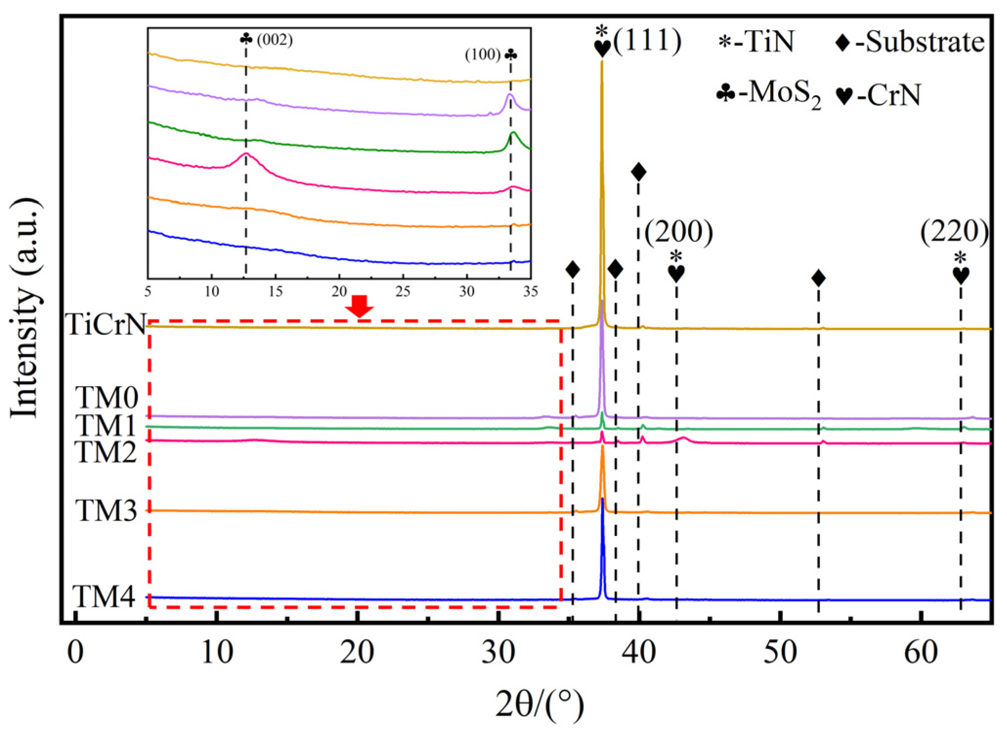
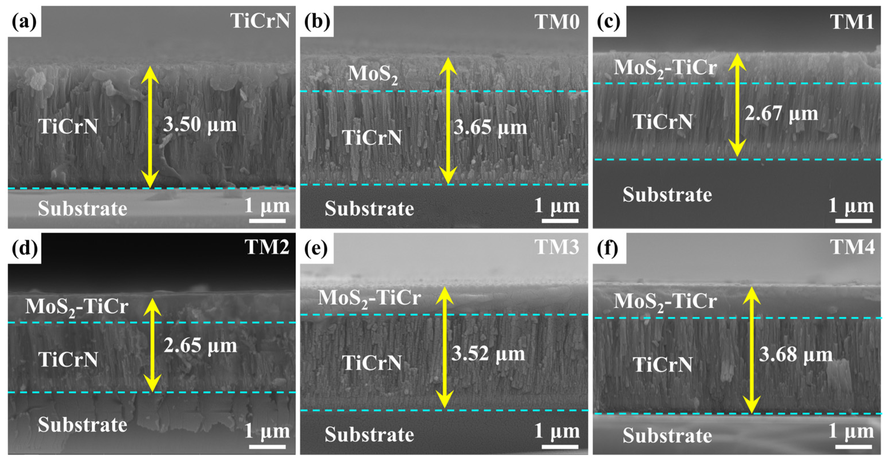
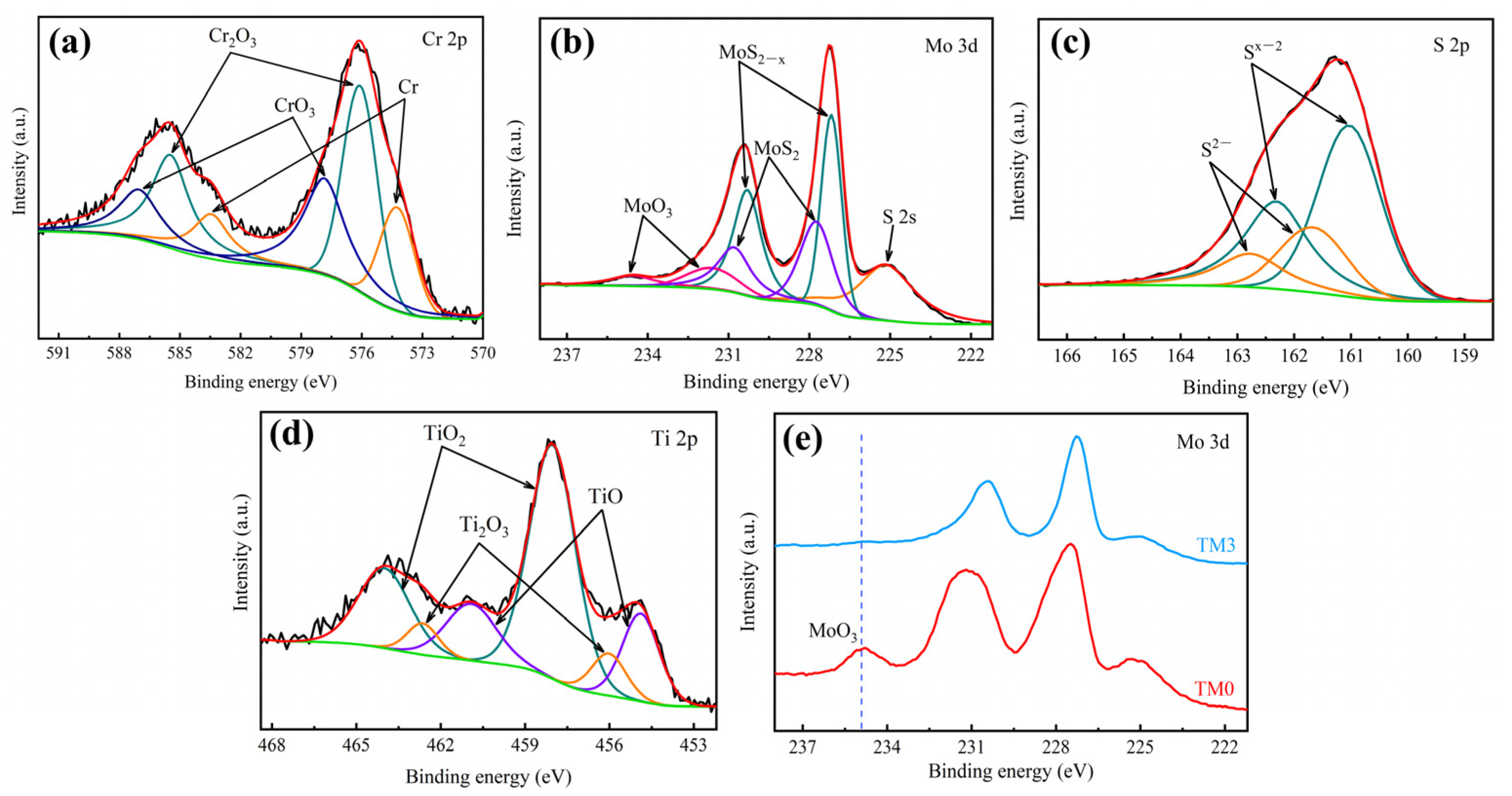
3.1. Structure and Morphology

The chemical compositions of the TiCrN, MoS2, and MoS2–TiCr layers analyzed by EDS are listed in Table 2. The results show that the coatings have different contents of oxygen elements, suggesting that all coatings have different degrees of oxidation. A possible reason for this is that the residual O2 in the sputtering chamber participated in the reaction, or the sample’s surface was oxidized when exposed to the atmosphere. In the top layer, with an increase in the current of the Ti target and the power of the Cr target, both the Ti and Cr element contents increased. In addition, the element content of the S and Mo decreased. Interestingly, the ratio of S/Mo in pure MoS2 and all MoS2–TiCr layers were less than 2, which ascribe to the reaction of sulfur with the residual atmosphere (especially with H2 and O2), and the preferential sputtering effect of sulfur caused by the bombardment of neutral argon atoms in the sputtering process [18,19]. Furthermore, the surfaces of TiCrN, TiCrN/MoS2 (TM0), and TiCrN/MoS2–TiCr (TM3) coatings were investigated by XPS. The results of the XPS survey spectra are shown in Figure 2. Distinctly, the percentages of O measured by XPS were much higher than those measured by EDS. This may have been attributed to the fact that the measuring depth of EDS was in micrometers while in XPS, it is nanometers. Commonly, the top surface of the coating is extremely susceptible to oxidization and easily adsorbs oxygen and water vapor. Moreover, it was also noted that in the XPS results, the percentage of O of the TiCrN and TM3 coatings was higher than the TM0 coating, suggesting that Ti and Cr may have captured more oxygen elements from the air than MoS2. According to reports by Lu et al. [16], Cr, Nb, Ti, and Al elements are more likely to react with oxygen in the air to form a dense oxide film than MoS2, which can effectively hinder the further diffusion of oxygen into the coating and reduce the degradation of MoS2.
The XRD patterns of all coatings are displayed in Figure 3. Clearly, the TiCrN layer of all coatings exhibits (111), (200), and (220) planes, and these planes are located at the TiN and CrN positions [8,20], with corresponding diffraction angles of 37.2°, 43.1°, and 63.1° (JCPDS card no. 87-0633 and 11-0065), respectively. It was also noticed that the TiCrN layer showed a strong (111)-preferred orientation, which was the lowest strain energy surface of the fcc B1 structure [21]. The small figure in the upper left corner of Figure 3 is the enlarged picture with respect to the diffraction angle (2θ) of 5° to 35°. It can be seen that except for the TiCrN coating, TM0 to TM4 coatings exhibited the (002) and (100) planes, which are characteristic peaks for the MoS2 (JCPDS card no. 75-1539). Moreover, with an increase in the sputtering time of Ti and Cr, the (002) plane became strong at first and then weak, and the intensity of the (100) plane gradually decreased. As reported by Bernd et al. [22], the (002) plane of MoS2 is parallel to the substrate, and the closed S layer on its surface forms a barrier to O2 and H2O. Meanwhile, when the (002) plane of MoS2 slides against the counterpart, it produces a smaller shear force compared to other crystal planes. In addition, the (002) and (100) peaks of TM3 and TM4 coatings almost disappear. This is due to the large number of Ti and Cr atoms entering the MoS2 crystal lattice in the MoS2–TiCr layer, which makes the long-range ordered state of MoS2 crystal become the short-range disordered state [23,24].
The surface morphologies of all coatings are shown in Figure 4. The surface of the TiCrN coating exhibits a cone-shaped tetrahedral morphology (Figure 4a), and the TM0 coating with pure MoS2 on the top layer shows a worm-like morphology (Figure 4b), similar to the reports of Zhang et al. [25]. As seen in Figure 4c,d, the surface morphology of the TM1 and TM2 coatings are compact. The surfaces of TM3 and TM4 coatings display the morphology of broccoli and hemisphere, respectively (Figure 4e,f). Figure 5 illustrates the cross-sectional morphologies of the as-deposited coatings. As can be seen in Figure 5a–f, the Ti and TiCr interlayer can be seen apparently in the cross-section topography of all coatings. Due to the development of the accumulated interface waves during the magnetron sputtering process, the TiCrN layer of all coatings shows obvious columnar crystal structures [26]. Evidently, the top layer of the TM0 coating shows a loose structure (Figure 5b). For TM1–TM4 coatings (Figure 5c–f), the loose structure of the top layer gradually became compact, indicating that an increased content of Ti and Cr elements in the top layer helped to increase the compactness of the coating. Additionally, the thicknesses of TiCrN, TM0, TM1, TM2, TM3, and TM4 coatings are 3500 nm, 3650 nm, 2670 nm, 2650 nm, 3520 nm, and 3680 nm, respectively (Figure 5). The sputtering time of each coating was 3 h. The average sputtering rates of TiCrN, TM0, TM1, TM2, TM3 and TM4 coatings were 0.33 nm/s, 0.35 nm/s, 0.25 nm/s, 0.25 nm/s, 0.34 nm/s and 0.35 nm/s, respectively, which were calculated using the following formula:
C = L T
where C is the average sputtering rate (nm/s), L is the thickness of the coating (nm) and T is the sputtering time (s).
Figure 6 shows the surface roughness of the as-deposited coatings. it can be intuitively seen that the surface roughness of the TiCrN coating is 18 nm. Furthermore, the surface roughness of the TM0–TM4 coatings is 12 nm, 10 nm, 8 nm, 9 nm, and 9 nm, respectively. Obviously, the TiCrN coating presents the highest surface roughness, and the TM2, TM3, and TM4 coatings show a low surface roughness. It can be seen from Figure 5a that the TiCrN coating grows with a coarse columnar crystal structure, which leads to high surface roughness. However, the doped Ti and Cr with the MoS2 help to increase the density of the top layer (Figure 5d–f), and, therefore, they show a low surface roughness.
The Cr 2p, Mo 3d, S 2p, and Ti 2p core-level XPS spectra corresponding to the selected TM3 coating surface are illustrated in Figure 7. As demonstrated in Figure 7a, Cr exists in three chemical states, Cr (574.2 eV and 583.5 eV), Cr2O3 (576.1 eV and 585.5 eV), and CrO3 (577.9 eV and 587.1 eV). The Mo 3d and S 2p peaks are shown in Figure 7b–c. The Mo 3d peak consisted of S 2s (225.2 eV), MoS2−x (227.2 eV and 230.3 eV), MoS2 (227.8 eV and 230.8 eV), and MoO3 (231.6 eV and 234.7 eV). The S 2p peak was composed of two components corresponding to Sx−2 (161.0 eV and 162.3 eV) and S2− (161.7 eV and 162.8 eV) [27,28]. As can be seen in Figure 7d, the Ti 2p peak was composed of three components corresponding to TiO (454.9 eV and 461.0 eV), TiO2 (458.1 eV and 464.0 eV) and Ti2O3 (456.1 eV and 462.6 eV) [29]. Clearly, the elements on the surface of TM3 coating mainly existed in the form of oxides. Figure 7e displays a comparison of XPS spectra of the Mo 3d for the TM0 and TM3 coatings. Compared to the TM0 coating, the MoO3 peak strength of the TM3 coating was significantly smaller. In the report of Li et al. [27], the Zr was more likely to preferentially react with O2, thereby reducing the degree of oxidation of the MoS2. The same phenomenon was observed in this work, and the Ti and Cr doping into the top layer seem to contribute to reducing the oxidation of MoS2.

3.2. Mechanical Properties

The hardness and elastic modulus of the coatings are shown in Figure 8. It can be seen that the hardness increased with an increase in the Ti and Cr deposition. In addition, the TiCrN coating showed the highest hardness and the MoS2 showed the lowest. According to the report of Özkan [30], the high hardness of the TiCrN coating is mainly due to the high strength of the covalent bonds. Compared to the TM0 coating, the TM1–TM4 coatings showed higher hardness and elastic modulus. This is ascribed to the doping of the Ti and Cr onto the top layer which can inhibit dislocation movement and grain boundary slip. Furthermore, the alternate sputtering method can hinder the growth of the columnar crystals, making the top layer become dense [16]. Therefore, a higher content of metal doping leads to an increase in the mechanical properties of the MoS2–TiCr layer.
The adhesion strength of the coating to the substrate significantly affects the tribological properties and service life of the coating. In our work, the scratch test was applied to obtain the critical load of the coatings and quantitatively evaluate the adhesion strength of the coating to the substrate. Generally, the sudden changes in the friction force curve and the abrupt changes in the friction coefficient are used to judge the coating failure. Figure 9 shows the friction force and the coefficient of friction curves in the scratch test of the coatings. As exhibited in Figure 9a–f, the friction force and the friction coefficient curves of the TiCrN, TM0, TM1, TM2, and TM4 coatings change suddenly in the load force of 26 N, 58 N, 22 N, 17 N, and 48 N, respectively. In particular, the TM3 coating did not fail when the loading force increased to 50 N, indicating that the TM3 coating had excellent adhesion to the substrate.
To further observe the failure process of the coatings during the scratch test, the scratch morphologies of all coatings were observed using a white light interferometer and confocal microscope. The scratch morphologies are displayed in Figure 10. Commonly, Lc1 is defined as the load force where cracks initiate, and Lc2 is defined as the load force where the coating is completely scratched. In the optical morphology of the scratch, the Lc2, where TiCrN-TM4 coatings were completely scratched, was consistent with the loading force where the turning point appears in Figure 9. The Lc1 of the TiCrN, TM0, TM1, TM2, TM3, and TM4 coatings are 15.7 N, 5.7 N, 7.6 N, 9.3 N, 20.0 N, and 28.9 N, respectively (Figure 10a–f). Distinctly, for the TM0–TM4 coatings, the higher the doping content of Ti and Cr in the top layer, the higher the Lc1. Namely, the TM4 coating is the most resistant to initial crack generation. This may be accounted for by the fact that internal stress is introduced when the MoS2 or MoS2–TiCr layer is deposited onto the surface of the TiCrN layer. Furthermore, an increase in internal stress reduces the resistance of the coating to the initiation of cracks. As a result, the TiCrN coating has good resistance to initial crack generation. Nevertheless, the top layer structure of the TM0, TM1 and TM2 coatings is loose, and under the action of external load, the internal stress is released along grain boundaries and pores, which leads to the generation of cracks. Moreover, the top layers of the TM3 and TM4 coatings are denser with fewer voids and grain boundaries, and both of them have good resistance to initial crack generation.

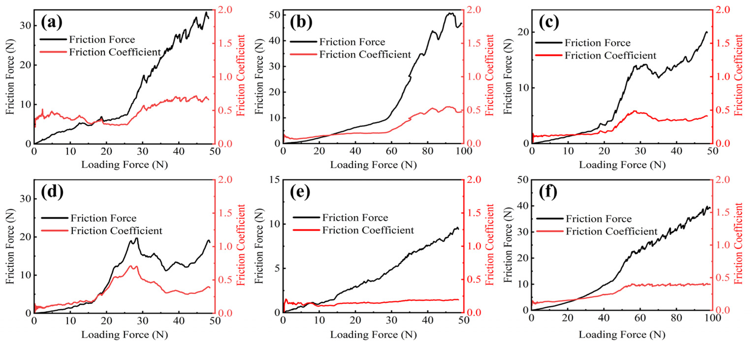
3.3. Tribology Performance

Figure 11 shows the friction coefficient and wear rate of the coatings under dry conditions in the atmospheric environment. As can be seen in Figure 11a, the TiCrN coating showed the highest friction coefficient of about 0.65. The friction coefficient of the TM0 coating was less than 0.17 in the initial 30 min and then increased to 0.45 instantly, suggesting that the TM0 coating was worn through. For the TM1 coating, the friction coefficient stabilized at 0.09 in the first 30 min and then stabilized at 0.14 in the last 30 min. Moreover, the friction coefficient of the TM3 coating was around 0.06, and the TM2 and TM4 coatings slightly fluctuated around 0.14 and 0.11, respectively. Therefore, it can be seen that the MoS2–TiCr layer greatly reduced the friction coefficient of the TiCrN layer, by more than 90%.
Figure 11b shows the wear rate of the coatings. It was noted that the TiCrN coating had a high wear rate of 38.4 × 10⁻⁶ mm3/N·m due to the absence of lubricant, leading to a large amount of material being removed by the counterpart and abrasive particle. The TM3 coating showed the lowest wear rate of around 2.3 × 10⁻⁶ mm3/N·m. In this study, the TM0 coating was worn out, so its wear rate was not counted. Generally speaking, coating with high hardness and compactness always accompanies good wear resistance [31]. The top layer (pure MoS2) of the TM0 coating was very loose, so the material was extremely easily removed by the counterpart and abrasive particles. The top layers of the TM3 coating and the TM4 coatings had sufficient hardness and compactness, and they provided enough framework support for the lubricant of wear scars. On the other hand, oxygen and water molecules can easily pass through the loose top layer of the TM0 coating and oxidize MoS2, resulting in poor friction and wear properties. According to the results of XPS spectra of Mo 3d in Figure 7e, Ti and Cr in the top layer of TiCrN/MoS2–TiCr composite coating can effectively prevent O atoms in oxygen and water molecules from reacting with MoS2 to produce MoO3. This manifested as an increase in the wear resistance of the coating and a reduction in the coefficient of friction of the coating. Unfortunately, although the TiCrN coating has sufficient hardness, it did not have excellent lubricating properties such as MoS2, which was the main reason for the high friction coefficient and high wear rate.
To further understand the wear mechanism of the coatings, the scanning electron microscope (SEM) and white light interferometry were used to observe the wear scars. Figure 12 exhibits the SEM images and 3D topographies of the wear scars. The wear scar width of the TiCrN coating was 259 μm (Figure 12(a1)), with cracks in the middle (Figure 12(a2)). It can be seen that the wear scar of the TiCrN coating was severely scratched (Figure 12(a3)). As shown in Figure 12(b1), the TM0 coating had the widest wear scar of 314 μm. Further, there were large tribal pits and a large number of furrows in the wear scar (Figure 12(b2)). Additionally, there were a lot of deep sharp-jagged furrows in the wear scar (Figure 12(b3)), suggesting that its wear mechanism was severe abrasive wear. For the TM1 coating (Figure 12(c1)), its wear scar width was greatly reduced compared to the TM0 coating. There were furrows on the wear scar, indicating that its wear mechanism was abrasive wear (Figure 12(c2)). As displayed in Figure 12(d1–d3), the wear width of the TM3 coating was the narrowest at 109 μm, and furrows and adhesives existed on its surfaces, indicating that its wear mechanism was abrasive and adhesive wear. Furthermore, the wear scars on the TM2 and TM4 coatings were smooth (Figure 12(d1,f1)). In particular, the wear scar edge of the TM2 coating displayed a peeling phenomenon (Figure 12(d1)), which is a typical adhesive wear characteristic. Additionally, the wear scar edge of the TM4 coating had adhesions (Figure 12(f2)), indicating that its wear mechanism was also adhesive wear. From the 3D topographies of the TM2 and TM4 coatings (Figure 12(d3,f3)), it can be clearly seen that both of the wear scars were smooth, which was consistent with the results of the SEM result.
Figure 13 illustrates the 2D cross-sectional curves of the wear scar of the coatings. Clearly, the TM0 sample had the largest wear scar width and depth. In addition, the wear depth of the TiCrN coating was 3.92 μm, indicating that the middle of the coating had been worn through because the thickness of the coating was 3.5 μm from the cross-sectional SEM images (Figure 5a). For the TM1–TM4 coatings, both the wear scar depth and width first decreased and then increased, which was consistent with the change in the wear rate.
The chemical composition and structure of the unworn area, the edge of the wear scar, and the center of the wear scar on the TM3 coating were analyzed using Raman spectroscopy, and the results are exhibited in Figure 14. For the unworn area and the edge of the wear scar, a broad peak appears around 260 cm−1. According to Li et al. [32], this peak corresponds to the scattering of band-edge phonons, and its appearance implies that the crystal orientation is disordered. As expected, this is consistent with the XRD results of the top layer of the TM3 coating, as shown in Figure 3. Compared to the unworn area, the center of the wear scar had significantly changed, indicating that the material in the center of the wear scar had undergone a structural transformation. It can be seen that the peaks of the central area of the wear scar located at 380.3 cm−1 and 413.3 cm−1 are assigned to the E12g peak and the A1g peak of MoS2, respectively. Particularly, the E12g peak is the result of the movement of Mo and S atoms in the x-y plane, and the A1g peak is the result of the movement of the S atom along the z axis [33]. Furthermore, the broad peaks around 526 cm−1 and 650 cm−1 were due to the second-order vibration of MoS2. Obviously, the characteristic peak of the crystalline MoS2 appeared in the central area of the wear scar, indicating that the recrystallization occurred in the middle of the wear scar. In the previous reports [32,34,35,36], the preferred orientation of the crystalline MoS2 in the middle area of the wear scar is the (002) crystal plane, which is parallel to the substrate. This is beneficial to improving the friction and wear properties of the coating.

4. Conclusions

In this paper, the TiCrN/MoS2–TiCr coatings were prepared on the surface of the titanium alloy (Ti-6Al-4V) using the magnetron sputtering method. Thereafter, the phase, microstructure, mechanical properties, and tribological properties of single TiCrN coating and the TiCrN/MoS2–TiCr composite coatings were compared. The results showed that as the content of Ti and Cr increased in the MoS2–TiCr top layer, the (002) crystal plane of MoS2 first strengthened and then weakened, the (100) crystal plane of MoS2 gradually disappeared, and the top layer gradually became amorphous. The cross-sectional morphology of the TiCrN coating showed a typical columnar crystal structure, and the top layer of the TiCrN/MoS2–TiCr coating became denser with increasing Ti and Cr content.
Compared to the single TiCrN coating, the surface roughness and hardness of the TiCrN/MoS2–TiCr coating were lower. The TiCrN/MoS2–TiCr coating (TM3 coating) with a content of 11.9 at.% Ti and 8.9 at.% Cr in the top layer had the best coating–substrate adhesion. The friction coefficient and wear rate of the TM3 coating were reduced by 90% and 94%, respectively, compared to the TiCrN coating. When the TiCrN/MoS2–TiCr coating slid against the counterpart, the amorphous MoS2 transformed into the crystalline MoS2. This may be the main reason for the excellent friction and wear properties of the TiCrN/MoS2–TiCr coating.

Author Contributions

Methodology, Z.T. and X.Y.; Validation, S.L.; Formal analysis, J.Z.; Writing—original draft preparation, X.Y.; Writing—review and editing, Z.T.; Supervision, Z.T.; Funding acquisition, J.Z. All authors have read and agreed to the published version of the manuscript.

Funding

This work was supported by the National Science Foundation of China (52165022), the Science and Technology Project of Guizhou Province ((2020)1Y415), and the incubation project of Guizhou University ((2019)24).

Institutional Review Board Statement

Not applicable.

Informed Consent Statement

Informed consent was obtained from all subjects involved in the study.

Data Availability Statement

Not applicable.

Conflicts of Interest

The authors declare no conflict of interest.

References

  1. Croccolo, D.; Agostinis, M.D.; Fini, S.; Olmi, G. Tribological properties of bolts depending on different screw coatings and lubrications: An experimental study. Tribol. Int. 2017, 107, 199–205. [Google Scholar] [CrossRef]
  2. Hegab, A.; Dahuwa, K.; Islam, R.; Cairns, A.; Khurana, A.; Shrestha, S.; Francis, R. Plasma electrolytic oxidation thermal barrier coating for reduced heat losses in IC engines. Appl. Therm. Eng. 2021, 196, 117316. [Google Scholar] [CrossRef]
  3. Kehal, A.; Saoula, N.; Abaidia, S.E.H.; Nouveau, C. Effect of Ar/N2 flow ratio on the microstructure and mechanical properties of Ti-Cr-N coatings deposited by DC magnetron sputtering on AISI D2 tool steels. Surf. Coat. Technol. 2021, 421, 127444. [Google Scholar] [CrossRef]
  4. Li, K.; Xu, G.; Huang, X.; Chen, Q.; Xie, Z.; Gong, F. Surface evolution analysis of CrxWyNz coatings on WC mold in glass molding process. Surf. Coat. Technol. 2020, 393, 125839. [Google Scholar] [CrossRef]
  5. Bai, H.; Zhong, L.; Kang, L.; Liu, J.; Zhuang, W.; Lv, Z.; Xu, Y. A review on wear-resistant coating with high hardness and high toughness on the surface of titanium alloy. J. Alloys Compd. 2021, 882, 160645. [Google Scholar] [CrossRef]
  6. Santecchia, E.; Hamouda, A.M.S.; Musharavati, F.; Zalnezhad, E.; Cabibbo, M.; Spigarelli, S. Wear resistance investigation of titanium nitride-based coatings. Ceram. Int. 2015, 41, 10349–10379. [Google Scholar] [CrossRef]
  7. Kameneva, A.; Karmanov, V. Physical and mechanical properties of the TixZr1−xN thin films. J. Alloys Compd. 2013, 546, 20–27. [Google Scholar] [CrossRef]
  8. Paksunchai, C.; Denchitcharoen, S.; Chaiyakun, S.; Limsuwan, P. Growth and Characterization of Nanostructured TiCrN Films Prepared by DC Magnetron Cosputtering. J. Nanomater. 2014, 2014, 1–9. [Google Scholar] [CrossRef] [Green Version]
  9. Li, S.; Deng, J.; Yan, G.; Zhang, K.; Zhang, G. Microstructure, mechanical properties and tribological performance of TiSiN–WS2 hard-lubricant coatings. Appl. Surf. Sci. 2014, 309, 209–217. [Google Scholar] [CrossRef]
  10. Lukaszkowicz, K.; Kubacki, J.; Balin, K.; Sondor, J.; Pancielejko, M. Characteristics of CrAlSiN+MoS2 coating deposited by cathodic arc and magnetron sputtering process. Vacuum 2019, 163, 360–367. [Google Scholar] [CrossRef]
  11. Lu, Y.; Deng, J.; Song, W.; Li, X.; Zhang, L.; Sun, J. Tribological performance of AlCrN–MoS2/PTFE hard-lubricant composite coatings. Proc. Inst. Mech. Eng. Part J J. Eng. Tribol. 2019, 234, 1355–1367. [Google Scholar] [CrossRef]
  12. Arslan, E.; Totik, Y.; Efeoglu, I. Comparison of structure and tribological properties of MoS2-Ti films deposited by biased-dc and pulsed-dc. Prog. Org. Coat. 2012, 74, 772–776. [Google Scholar] [CrossRef]
  13. Stoyanov, P.; Strauss, H.W.; Chromik, R.R. Scaling effects between micro- and macro-tribology for a Ti–MoS2 coating. Wear 2012, 274–275, 149–161. [Google Scholar] [CrossRef]
  14. Zhou, Z.; Wen, Q.; Wan, Z.; Sang, R. The effect of Ti content on the structural and mechanical properties of MoS2 Ti composite coatings deposited by unbalanced magnetron sputtering system. Phys. Procedia 2011, 18, 234–239. [Google Scholar] [CrossRef] [Green Version]
  15. Ding, X.Z.; Zeng, X.T.; He, X.Y.; Chen, Z. Tribological properties of Cr- and Ti-doped MoS2 composite coatings under different humidity atmosphere. Surf. Coat. Technol. 2010, 205, 224–231. [Google Scholar] [CrossRef]
  16. Lu, X.; Yan, M.; Yan, Z.; Chen, W.; Sui, X.; Hao, J.; Liu, W. Exploring the atmospheric tribological properties of MoS2-(Cr, Nb, Ti, Al, V) composite coatings by high throughput preparation method. Tribol. Int. 2021, 156, 106844. [Google Scholar] [CrossRef]
  17. Li, L.; Lu, Z.; Pu, J.; Wang, H.; Li, Q.; Chen, S.; Zhang, Z.; Wang, L. The superlattice structure and self-adaptive performance of C–Ti/MoS2 composite coatings. Ceram. Int. 2020, 46, 5733–5744. [Google Scholar] [CrossRef]
  18. Zhao, X.; Zhang, G.; Wang, L.; Xue, Q. The Tribological Mechanism of MoS2 Film under Different Humidity. Tribol. Lett. 2017, 65, 1–8. [Google Scholar] [CrossRef]
  19. Wang, Z.; Cai, Z.; Sun, Y.; Peng, J.; Zhu, M. Low velocity impact wear behavior of MoS2/Pb nanocomposite coating under controlled kinetic energy. Surf. Coat. Technol. 2017, 326, 53–62. [Google Scholar] [CrossRef]
  20. Chen, S.; Luo, D.; Zhao, G. Investigation of the Properties of TixCr1-xN Coatings Prepared by Cathodic Arc Deposition. Phys. Procedia 2013, 50, 163–168. [Google Scholar] [CrossRef]
  21. Kabir, M.S.; Munroe, P.; Zhou, Z.; Xie, Z. Structure and mechanical properties of graded Cr/CrN/CrTiN coatings synthesized by close field unbalanced magnetron sputtering. Surf. Coat. Technol. 2017, 309, 779–789. [Google Scholar] [CrossRef]
  22. Vierneusel, B.; Schneider, T.; Tremmel, S.; Wartzack, S.; Gradt, T. Humidity resistant MoS2 coatings deposited by unbalanced magnetron sputtering. Surf. Coat. Technol. 2013, 235, 97–107. [Google Scholar] [CrossRef]
  23. Banerjee, T.; Chattopadhyay, A.K. Structural, mechanical and tribological properties of pulsed DC magnetron sputtered TiN–WSx/TiN bilayer coating. Surf. Coat. Technol. 2015, 282, 24–35. [Google Scholar] [CrossRef]
  24. Kong, N.; Wei, B.; Li, D.; Zhuang, Y.; Sun, G.; Wang, B. A study on the tribological property of MoS2/Ti–MoS2/Si multilayer nanocomposite coating deposited by magnetron sputtering. RSC Adv. 2020, 10, 9633–9642. [Google Scholar] [CrossRef] [PubMed]
  25. Zhang, X.; Qiao, L.; Chai, L.; Xu, J.; Shi, L.; Wang, P. Structural, mechanical and tribological properties of Mo–S–N solid lubricant films. Surf. Coat. Technol. 2016, 296, 185–191. [Google Scholar] [CrossRef]
  26. Lu, C.; Jia, J.; Fu, Y.; Yi, G.; Feng, X.; Yang, J.; Zhou, Q.; Xie, E.; Sun, Y. Influence of Mo contents on the tribological properties of CrMoN/MoS2 coatings at 25–700 °C. Surf. Coat. Technol. 2019, 378, 125072. [Google Scholar] [CrossRef]
  27. Li, L.; Lu, Z.; Pu, J.; Hou, B. Investigating the tribological and corrosive properties of MoS2/Zr coatings with the continuous evolution of structure for high-humidity application. Appl. Surf. Sci. 2021, 541, 148453. [Google Scholar] [CrossRef]
  28. Lince, J.R.; Loewenthal, S.H.; Clark, C.S. Tribological and chemical effects of long-term humid air exposure on sputter-deposited nanocomposite MoS2 coatings. Wear 2019, 432–433, 202935. [Google Scholar] [CrossRef]
  29. Li, H.; Li, X.; Zhang, G.; Wang, L.; Wu, G. Exploring the Tribophysics and Tribochemistry of MoS2 by Sliding MoS2/Ti Composite Coating Under Different Humidity. Tribol. Lett. 2017, 65, 1–10. [Google Scholar] [CrossRef]
  30. Özkan, D.; Yılmaz, M.A.; Erdem, C.; Türküz, C.; Sulukan, E.; Yağcı, M.B. Wear and friction behavior of CrTiN/TiCN and CrTiN/CrCN multilayer composite coatings. Ceram. Int. 2022, 48, 13732–13747. [Google Scholar] [CrossRef]
  31. Gui, B.; Zhou, H.; Zheng, J.; Liu, X.; Feng, X.; Zhang, Y.; Yang, L. Microstructure and properties of TiAlCrN ceramic coatings deposited by hybrid HiPIMS/DC magnetron co-sputtering. Ceram. Int. 2021, 47, 8175–8183. [Google Scholar] [CrossRef]
  32. Li, Y.; Xie, M.; Sun, Q.; Xu, X.; Fan, X.; Zhang, G.; Li, H.; Zhu, M. The effect of atmosphere on the tribological behavior of magnetron sputtered MoS2 coatings. Surf. Coat. Technol. 2019, 378, 125081. [Google Scholar] [CrossRef]
  33. Yaqub, T.B.; Vuchkov, T.; Bruyère, S.; Pierson, J.F.; Cavaleiro, A. A revised interpretation of the mechanisms governing low friction tribolayer formation in alloyed-TMD self-lubricating coatings. Appl. Surf. Sci. 2022, 571, 151302. [Google Scholar] [CrossRef]
  34. Gu, L.; Ke, P.; Zou, Y.; Li, X.; Wang, A. Amorphous self-lubricant MoS2-C sputtered coating with high hardness. Appl. Surf. Sci. 2015, 331, 66–71. [Google Scholar] [CrossRef]
  35. Krauß, S.; Seynstahl, A.; Tremmel, S.; Meyer, B.; Bitzek, E.; Göken, M.; Yokosawa, T.; Zubiri, B.A.; Spiecker, E.; Merle, B. Structural reorientation and compaction of porous MoS2 coatings during wear testing. Wear 2022, 500–501, 204339. [Google Scholar] [CrossRef]
  36. Xu, J.; He, T.F.; Chai, L.Q.; Qiao, L.; Zhang, X.Q.; Wang, P.; Liu, W.M. Selective-releasing-affected lubricant mechanism of a self-assembled MoS2/Mo-S-C nanoperiod multilayer film sliding in diverse atmospheres. Phys. Chem. Chem. Phys. 2017, 19, 8161–8173. [Google Scholar] [CrossRef]
Figure 1. The structure of the coatings: (a) TiCrN, (b) TiCrN/MoS2 and (c) TiCrN/MoS2–TiCr coatings.
Coatings 12 01844 g001
Figure 2. XPS survey spectra of (a) TiCrN, (b) TM0, and (c) TM3 coatings.
Coatings 12 01844 g002
Figure 3. XRD patterns of as-deposited coatings.
Coatings 12 01844 g003
Figure 4. Surface topography of (a) TiCrN, (b) TM0, (c) TM1, (d) TM2, (e) TM3, and (f) TM4 coatings.
Coatings 12 01844 g004
Figure 5. Cross-sectional morphology of (a) TiCrN, (b) TM0, (c) TM1, (d) TM2, (e) TM3, and (f) TM4 coatings.
Coatings 12 01844 g005
Figure 6. The surface roughness of (a) TiCrN, (b) TM0, (c) TM1, (d) TM2, (e) TM3, and (f) TM4 coatings.
Coatings 12 01844 g006
Figure 7. XPS spectra. (a) Cr 2p, (b) Mo3d, (c) S 2p and (d) Ti 2p peaks of TM3 coating. (e) Mo 3d peak of TM0 and TM3 coatings.
Coatings 12 01844 g007
Figure 8. (a) Hardness and (b) elastic modulus of the coatings.
Coatings 12 01844 g008
Figure 9. The friction coefficient and friction force curves with the loading force in scratch tests for (a) TiCrN, (b) TM0, (c) TM1, (d) TM2, (e) TM3, and (f) TM4 coatings.
Coatings 12 01844 g009
Figure 10. The images of the scratch of (a) TiCrN, (b) TM0, (c) TM1, (d) TM2, (e) TM3, and (f) TM4 coatings.
Coatings 12 01844 g010
Figure 11. (a) Friction coefficient curves and (b) wear rates of the coatings.
Coatings 12 01844 g011
Figure 12. SEM images (a1f1), SEM magnified images (a2f2), and 3D topographies (a3f3) of the wear scar.
Coatings 12 01844 g012
Figure 13. 2D cross-sectional curves of the wear scars.
Coatings 12 01844 g013
Figure 14. The Raman characterization of the unworn region and wear scar of the TM3 coating.
Coatings 12 01844 g014
Table 1. Magnetron sputtering parameters of coating top layer.
ParameterTiCrNTM0TM1TM2TM3TM4
Target
current/power (A/W)
Ti-0.75 A
Cr-230 W
MoS2-200 WTi-0.1 A
Cr-35 W
MoS2-200 W
Ti-0.15 A
Cr-45 W
MoS2-200 W
Ti-0.2 A
Cr-55 W
MoS2-200 W
Ti-0.25 A
Cr-65 W
MoS2-200 W
Table 2. The EDS results of TiCrN, MoS2, and MoS2–TiCr layers.
SamplesAtomic Percentage (at.%)S/Mo
TiCrNSMoO
TiCrN15.529.850.4--4.2-
TM0---59.734.16.21.7
TM18.73.7-49.628.59.41.7
TM29.46.0-45.927.510.91.6
TM311.98.9-42.926.89.91.6
TM416.611.9-40.222.28.81.8
Publisher’s Note: MDPI stays neutral with regard to jurisdictional claims in published maps and institutional affiliations.

