Article

Influence of Pre-Tinning Process on Coating Morphology and Interface Structure of Low Carbon Steel Dipped in Molten 6061 Al Alloy

by
Naglaa Fathy
1,
Khaled Saad Abdel Halim
2,3,*,
K. M. Hafez
3,
Mohamed Ramadan
2,3,
Badreddine Ayadi
2,4,
Abdulaziz S. Alghamdi
2 and
Khaled M. Ibrahim
3
1
Department of Physics, College of Science, University of Hail, Hail P.O. Box 2440, Saudi Arabia
2
College of Engineering, University of Hail, Hail P.O. Box 2440, Saudi Arabia
3
Central Metallurgical Research and Development Institute (CMRDI), Helwan 11421, Egypt
4
Laboratory of Applied Fluid Mechanics, Environment and Process Engineering ”LR11ES57”, National School of Engineers of Sfax (ENIS), University of Sfax, Route Soukra Km 3.5, Sfax 3038, Tunisia
*
Author to whom correspondence should be addressed.
Coatings 2022, 12(10), 1499; https://doi.org/10.3390/coatings12101499
Submission received: 8 September 2022 / Revised: 23 September 2022 / Accepted: 6 October 2022 / Published: 8 October 2022
(This article belongs to the Special Issue Surface Function Enhancement Film and Coating Technology)

Abstract

:
Pre-treated low carbon steel specimens with flux or flux + tin mixture were coated by hot-dip aluminizing process. Al alloy (6061) was melted and hold at 750 °C. Fluxed and pre-tinned low carbon steel samples were dipped in a molten bath for time intervals of 0.5, 1, 2.5 and 3.5 min. Applying double coating processes via tinning-aluminizing techniques facilitated the formation of Fe-Al intermetallic interface and increasing the thickness of homogenous coating layer over the substrate material. The presence of Sn facilitates to great extent the formation of a better interlayer-free bond of residual flux and/or oxides. The fluxed–dipped steel substrates have inhomogeneous distribution of Al alloy coating as well as an interface with residual flux and oxides for dipping time up to 2.5 min. A homogenous distribution with good thickness morphology of the Al alloy coating and homogeneous thin intermetallic interface was achieved for tinned steel substrate at all applied dipping times. The comparison between the pre-tinning and pre-fluxing processes on steel substrates showed a significant effect of tinning over fluxing treatment acting on the thickness layer of Al-coating and interface using a short time dipping. For dipping time up to 2.5 min, the hardness of pre-tinning substrates is greater than that of fluxed ones due to the presence of residual flux and void interface in fluxed steel.

1. Introduction

Low carbon steel (LCS) or what is called mild steel with a percentage of carbon up to 0.3% has moderate strength, high ductility and lighter weight due to the low carbon content and adding of some other alloys. The LCS alloys are very widespread, in which they are used in many advanced engineering materials applications, such as petrochemicals, metallurgical industrials, automotives, and electronic devices. In most of these applications, LCS is used at relatively high temperatures that makes it corrode easily in short times. Hence, it becomes unfit for using in a wide variety of end-use applications. The corrosion effects always minimize the lifetime, functionality and safety of metallic parts. The coatings of LCS is considered the best way to protect it from corrosion and greatly enhance the surface properties of such alloys.
Many coated materials were suggested based on the proposed technique. One of the promising techniques is aluminide coating using electroplating, chemical vapor deposition and hot-dip aluminizing. The former method is widely used in coating of LCS due to its simplicity, low cost and high production efficiency [1,2]. One of the common mechanism promoting the corrosion resistance ability of aluminide steels is the formation of a protective, dense and stable Al2O3 layer on the surface of the aluminide layer on steels during the oxidation process. The coating process via aluminizing technique is always associated with phase transformation of the aluminide layer from Al-rich into Fe-rich intermetallic phases [3,4,5]. The phase transformation at the interface of coating layer and LCS substrate and the formation of intermetallic compounds (IMCs) greatly reduce the adhesive strength and the formation of a mechanical bond between coating layer and substrate. Accordingly, the coated layer over the metallic substrates during hot-dip aluminizing coating process should be adjusted and optimized.
Many researchers from different points of view investigated the morphology and interface characteristics of the coating layer during hot-dip aluminizing techniques [6,7,8,9,10]. Generally, hot-dip aluminizing can be divided into two types, hot dipping in pure aluminum and hot dipping in aluminum alloys, based on the composition of the used molten baths [6]. Abdul Khaliq et al., [7] investigated the intermetallic compound interfacial layers formation between 316 L stainless steel and Al–Zn–Si coating alloy under industrial coating conditions. They found that the interfacial layer is composed of two distinct intermetallic compounds, the layer adjacent to the steel substrate is Fe2Al5 and that formed adjacent to the AZ coating alloy is FeAl3. The thermodynamic analysis also predicted the formation of AlCr and AlNi IMC particles. In another study [8], the analysis of the different phases formed on steel substrate after hot dipping in Al–Si–Mg alloy melt at 700 °C for 0.5, 1, 3 and 6 min reported the presence of Al3FeSi2 and Al2FeSi phases along with elemental Si and Mg in the form of Mg2Si. The Si exist as isolated islands across the coating and up to the intermetallic layer apart from its association with Mg in the form of Mg2Si. This study also revealed ternary Fe–Al–Si intermetallic Al3FeSi2 and Al2FeSi phases scattered in the intermetallic layer. In order to improve the mechanical properties and durability of the Al-coated steel, Si was added to the Al bath to decrease the thickness of the undesirable intermetallic compound layer and to generate less brittle Fe–Al–Si ternary compounds [9,10].
On the other hand, the surface properties and corrosion resistance of LCS alloys can be improved via coating the steel alloys with tin composite paste (direct tinning process) [11,12,13,14,15]. This kind of tinning technique will enable steel alloys to be highly corrosion, wear and oxidation resistance. The tin coating layer will greatly enhance the surface properties of the steel alloys, consequently, increasing their lifetime, and protecting them from corrosion. The improvement in surface properties will greatly enhance the mechanical properties of steel alloys that make them more feasible for advanced engineering applications. However, in related investigations, the authors of the present work used the direct tinning technique as a promising way of coating to protect steel alloys from corrosion [11,12,13,14,15]. The optimization of the tinning process of LCS substrate after incorporating flux constituents with the tin powder was handled to improve the bonding strength between steel substrate and coating layer and consequently, enhance the overall mechanical properties of steel alloys. It was found that the addition of nanoparticles, such as alumina nanoparticles [14] or ZnO/NiO nanoparticles [15], to tin composite of coatings are greatly affects the interfacial microstructures and corrosion behavior of LCS. It can be reported that the coating tin composite layer containing a certain amount of nanoparticles is highly recommended for achieving long life and high performance corrosion resistance of coated LCS with minimal coating layer defects.
Based on the above background, the present work introduces a novel technique to protect LCS from corrosion, including the combination of both tinning and hot-dip aluminizing processes. The surface and interface properties enhancement accompanying the coating of low carbon mild steel by Sn element and hot-dip aluminizing processes for short times were investigated. The interfacial microstructure changes for the produced coated materials together with the mechanical properties were investigated under different operation conditions. The influence of dipping temperatures and times on the surface coating morphology and interface structure of aluminide low carbon mild steel using the tinning-aluminizing techniques was demonstrated.

2. Experimental

2.1. Fluxing and Pre-Tinning Process

In the present study, eight specimens of LCS substrates of approximately 42 × 18 × 7 mm3 were grinded with emery papers of up to 400 grades (namely S1 to S8). The first four specimens (S1–S4) were pre-treated with flux materials by dipping steel substrates into flux mixture for 2.5 min. The flux constituents were 24 g of ZnCl2, 6 g of NaCl, 3 g of NH4Cl, 1 mL of HCl and 1 mL of H2O. The other four specimens (S5–S8) were coated with Sn-metal via direct tinning process [11,12,13,14,15]. The tinning of the steel substrates involves powder tin and flux mixture (flux constituents of 24 g ZnCl2, 6 g NaCl, 3 g NH4Cl, 1 mL HCl and 1 mL H2O). For the tinning process of steel substrates, 1 g of powder pure Sn (with grain size ≈ 50 μm) was mixed with 10 g of flux. A layer of Sn- flux mixture amounting to 0.2 g/cm2 was distributed on the steel surface area (42 mm × 18 mm). The steel substrates with an Sn-flux mixture were heated using a hotplate for 2.5 min at 350 °C. After the tinning process, the steel substrates were cooled and washed using warm water to remove the remaining flux on the surface of tin layer [11,12,13,14,15]. Table 1 displays the chemical compositions of the steel substrates and 6061 aluminum coating alloy used in the current study.

2.2. Hot-Dip Process

The LCS substrates which fluxed and/or tinned were immersed in the molten aluminum alloy bath under inert atmosphere (argon gas). A certain amount of aluminum coating alloy (300 g) was melted in a muffle furnace at 750 °C. The LCS substrates were immersed in the molten aluminum alloy and hanged with the steel spoon at regular time intervals (0.5, 1, 2.5 and 3.5 min). The specimens were removed from the alloy melt and allowed to cool at room temperature and were sectioned for further analysis.

2.3. Characterization

The produced specimens (S1–S8) were cross-sectional cut, grinded with emery papers of up to 1200 mesh, polished and etched with nital of 4% HNO3 and ethyl alcohol for microstructural investigations. An optical microscope and scanning electron microscope (SEM), ‘FEI Co., Brno, Czech Republic, accelerating voltage 20 kV’ were used to investigate the surface morphology and the structure of the coated layers. The chemical compositions of the interfaces of the coated layers were determined by energy-dispersive X-ray spectroscopy (EDAX) analysis using the standardless ZAF quantification method. The thickness of the surface layers was measured using a micrograph image analysis from software (Image Analyzer Software, Olympus GX51, Tokyo, Japan version). The thickness of the formed layers was measured at the different areas of the micrograph to confirm our results. The average thickness layer was obtained for each sample. Microhardness tests were performed using 50-g loads for a minimum of five points measured in each specimen.

3. Results and Discussion

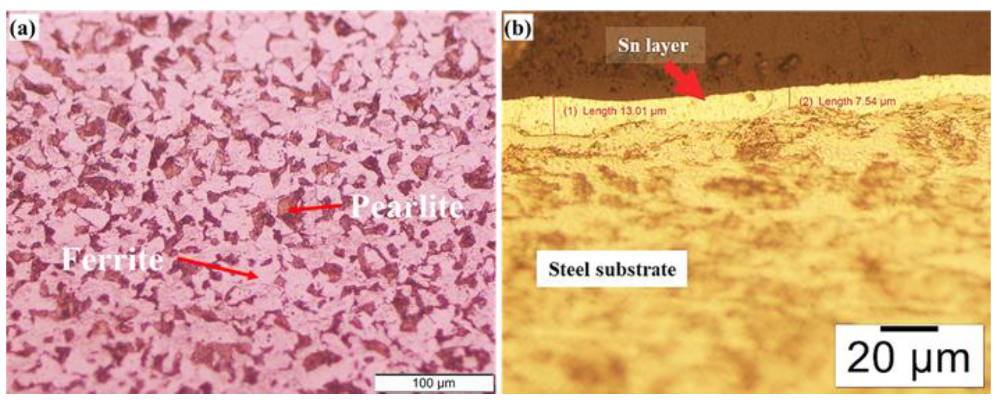
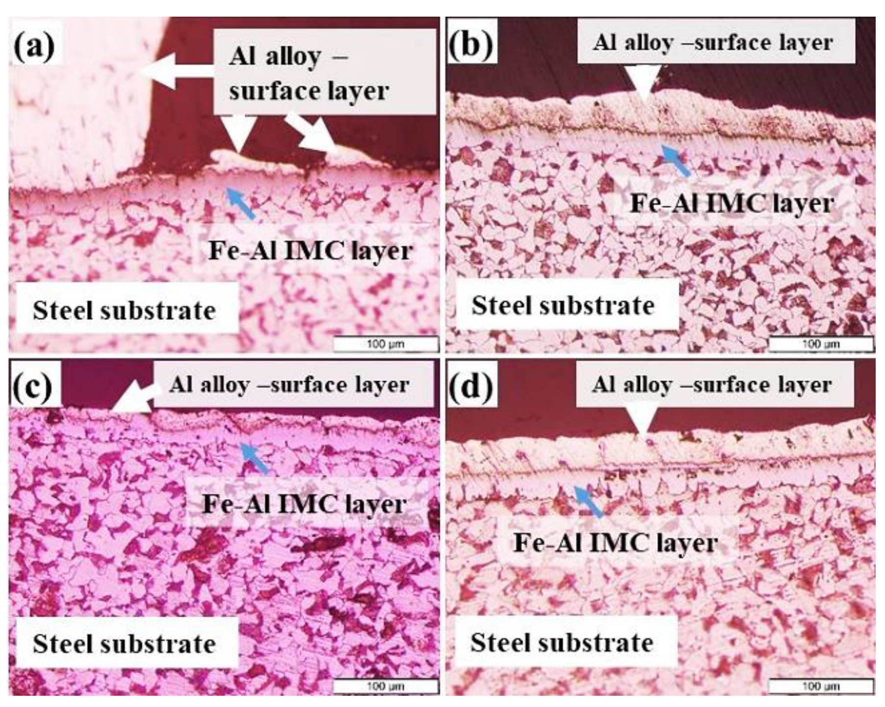
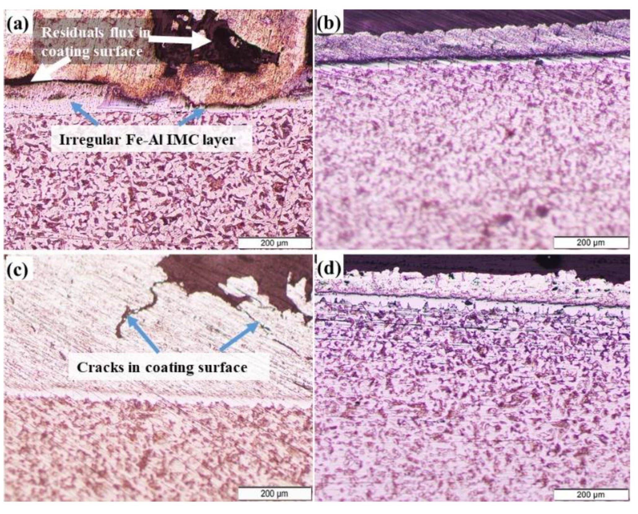
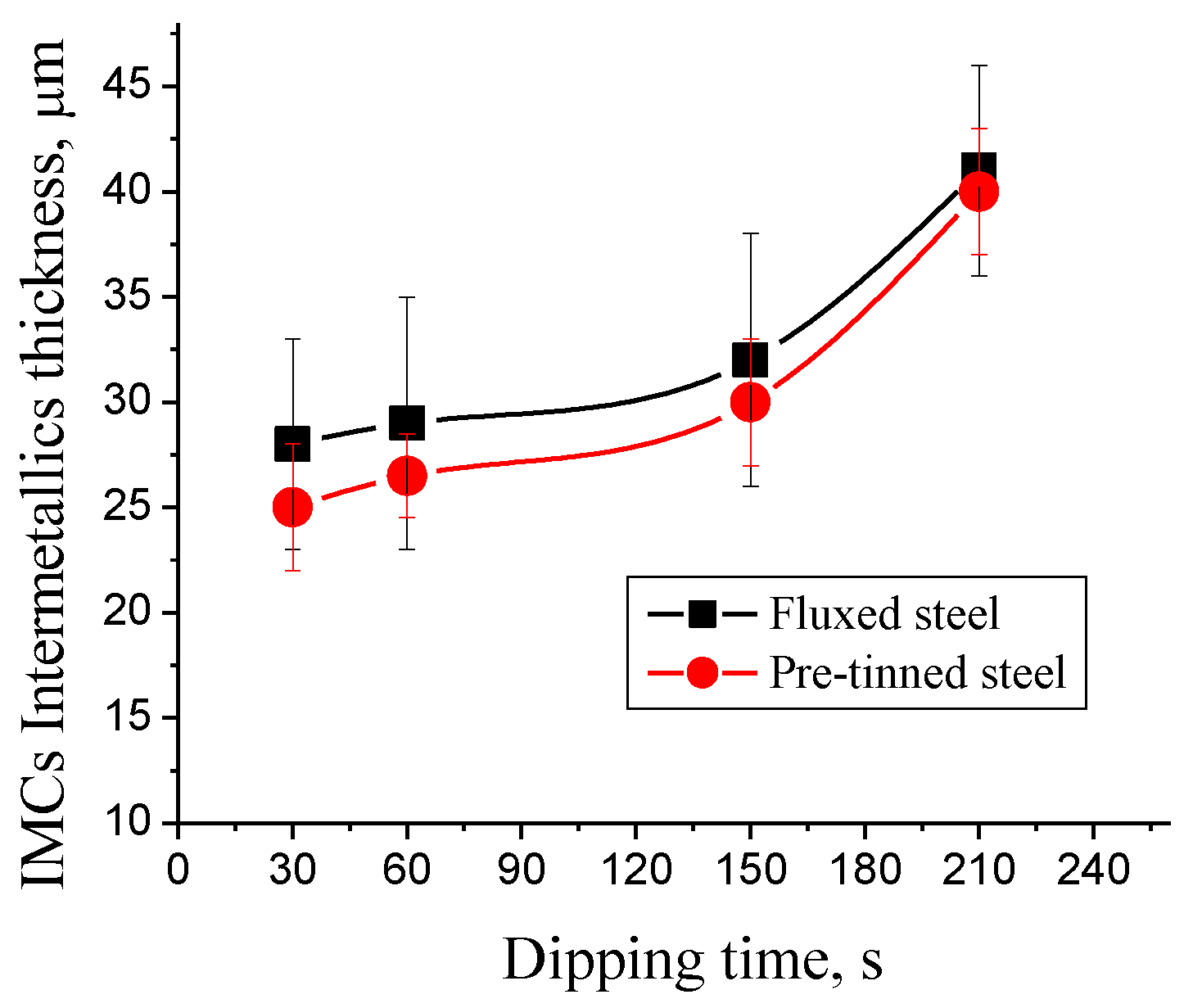
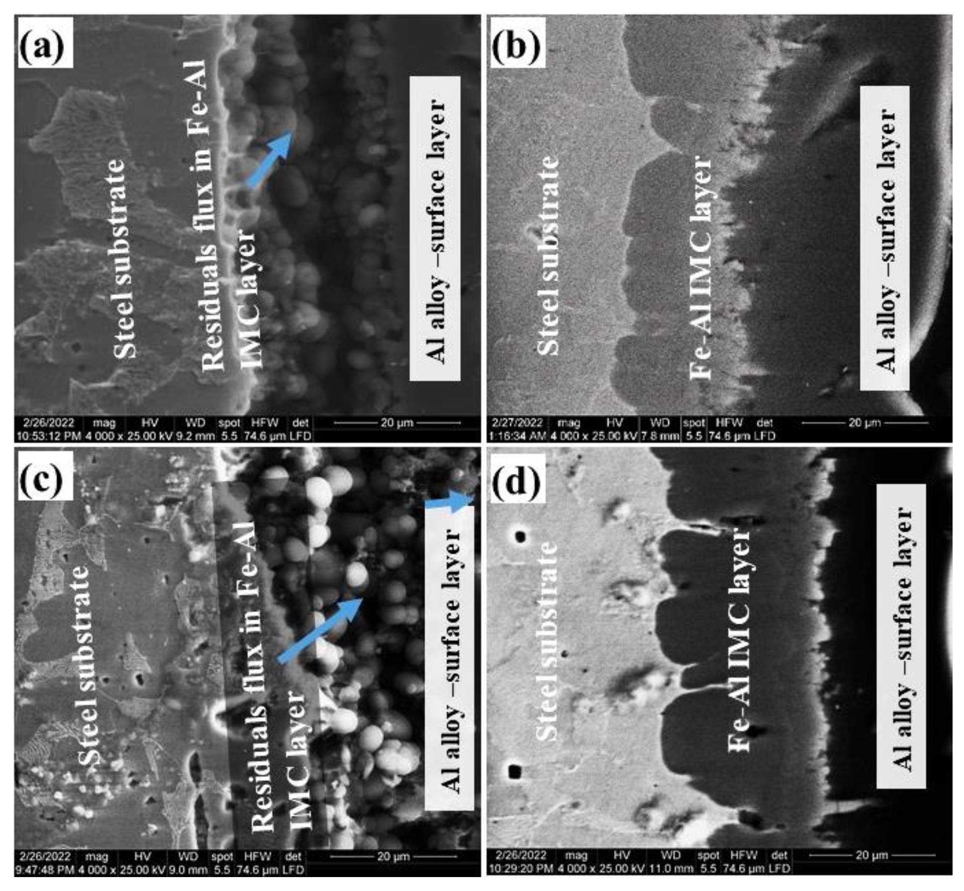
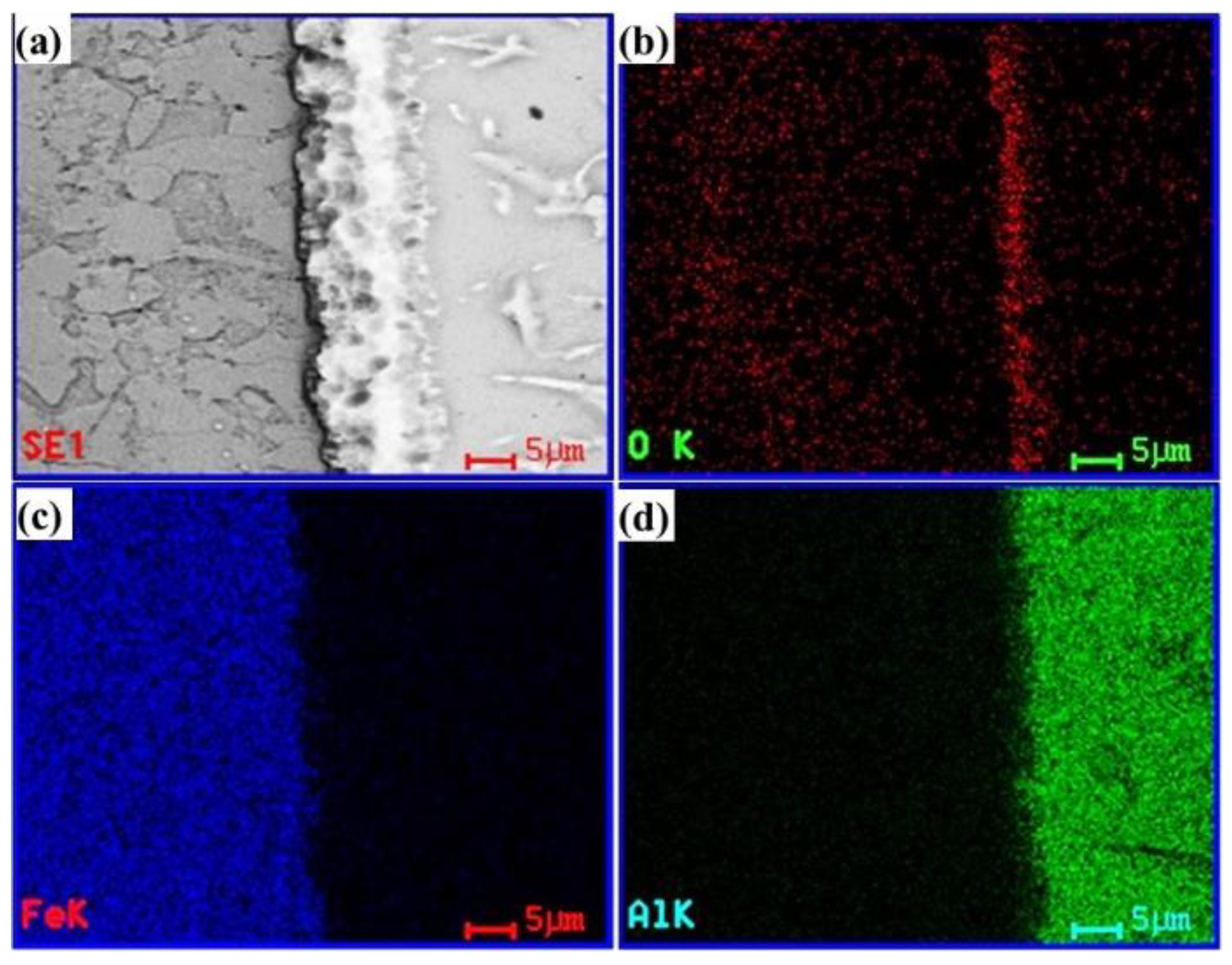
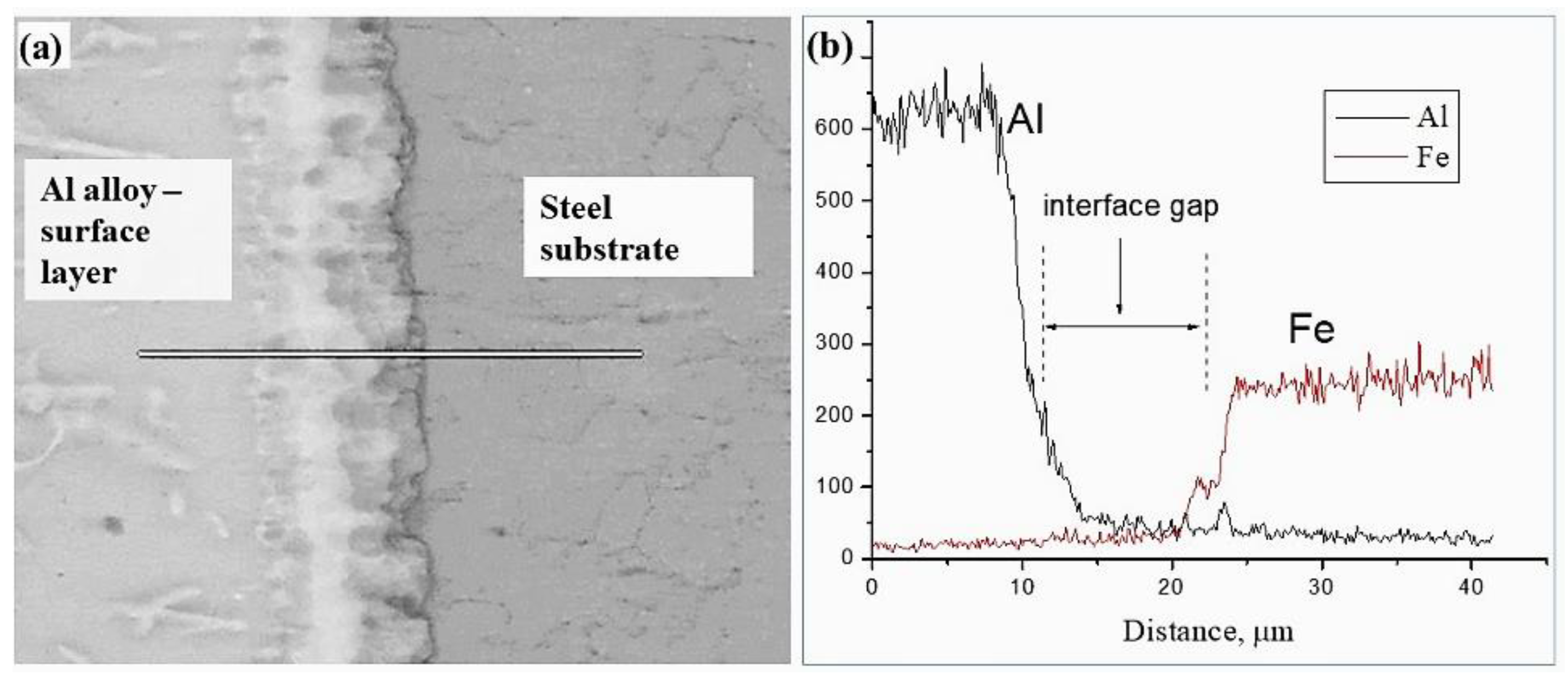
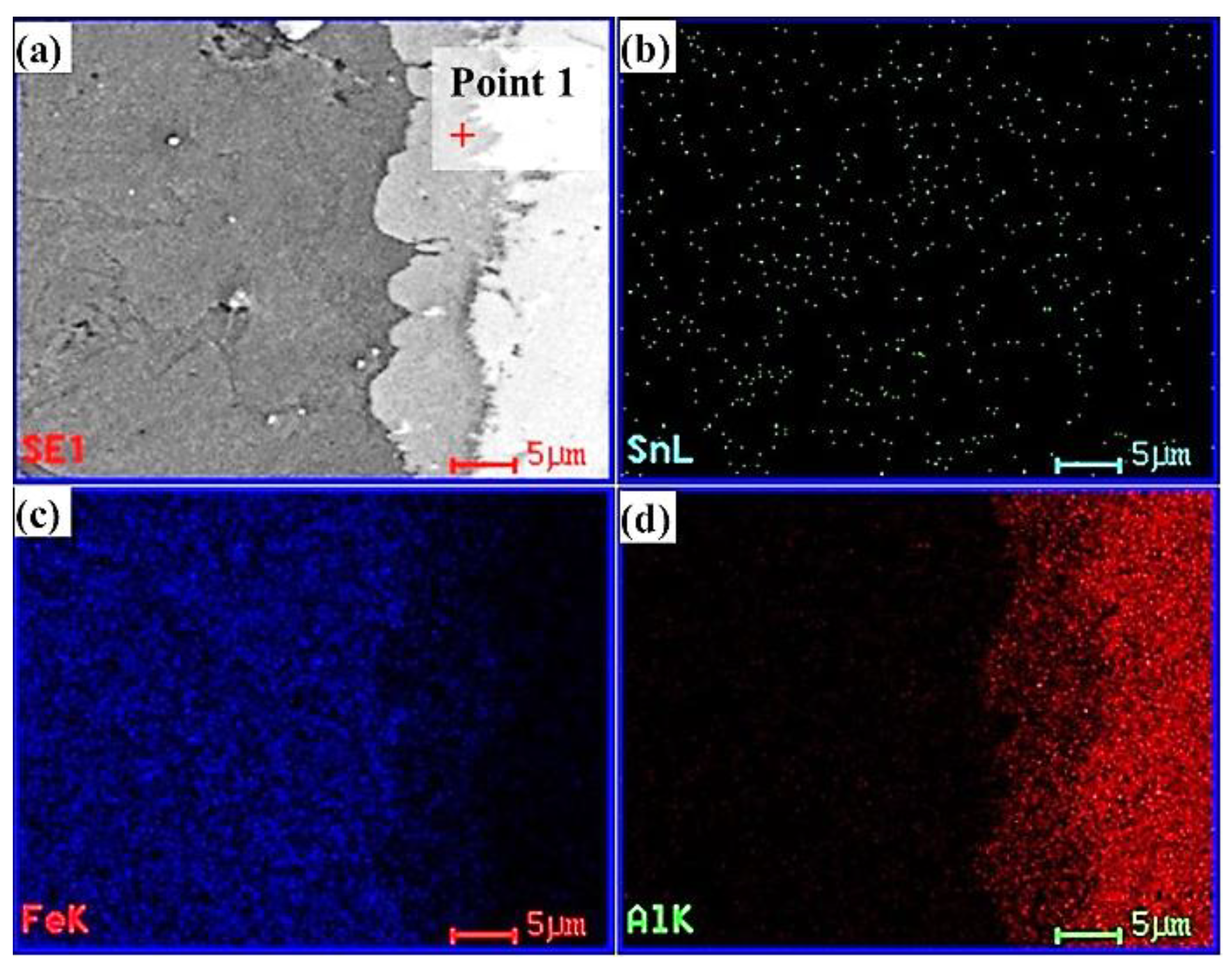
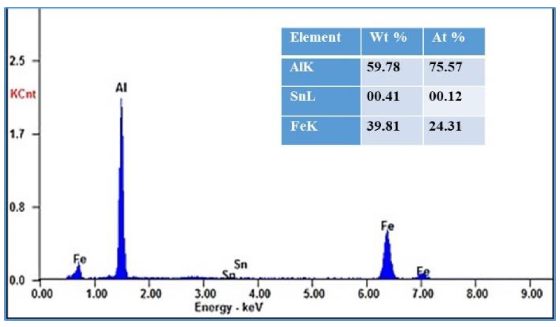
3.1. Microstructural Changes Accompanying Coating Process

The microstructures of LCS used in the present work and initial microstructure of pre-tinned steel before the dipping process is shown in Figure 1. The main phases of ferrite and pearlite can be distinguished clearly. It is well known that the percentage of the two phases primarily verifies the carbon % in the mild steel. LCS is the most extensively used engineering material for its outstanding mechanical properties, its reasonable conductivity and its cost efficiency [16]. However, LCS and other types of steel alloys are considered reactive materials that easier to corrode in different environmental systems. Barrier coatings [17] have been used to protect it from corrosion. A tinned steel before dipping process have a Sn-surface layer of average thickness 10.2 μm is shown in Figure 1b.
Figure 2 shows the microstructures of LCS with hot-dip aluminum coating. Different images were taken to reflect the effects of pre-treatment processes on the microstructures of the coating layers after hot-dip aluminizing process. It is interesting to mention firstly that the aim of pretreatment process is to prevent any possible oxidation reactions on the surface of steel substrate through formation of isolated layer and consequently ensure the strength of the formed mechanical bonds in the coating layers. In the case of the fluxing pretreatment process (Figure 2a,c), un-homogenous distribution of Al alloy coating can be detected. On the other hand, a homogenous distribution, which means a good thickness morphology of the Al alloy coating, can be observed in the pre-tinning specimens (Figure 2b,d). It is evident that the morphology and thickness of coatings are highly affected by the chemical composition of coating layers and the strength of the mechanical bond between coatings and steel substrates. However, this kind of un-homogeneity of Al alloy distribution can be minimized in long time dipping, as shown in Figure 2c,d.
To confirm the above finding and investigate the benefits of the pre-tinning process over the fluxing process, dipping of fluxed steel specimens was performed at 1 min and 3.5 min as shown in Figure 3. Irregular Fe-Al intermetallic layer is observed in Figure 3a for steel specimens dipped for 1 min. These intermetallic layers are associated with the presence of residual flux in the coating surface layer. Moreover, with increasing dipping time to 3 min, as shown in Figure 3c, some cracks in the coating Al layer can be detected, which can be attributed to the very weak mechanical bond between steel substrate and Al coatings. In comparison with steel substrates in which the surface is treated with Sn and dipped in Al coatings, a clear morphology thickness can be observed indicating a strong cohesive bond between coatings and steel substrate (Figure 3b,d).
The thickness of Al alloy coatings plays an important role in the properties of LCS against corrosion and other environmental parameters. Figure 4 shows the relation between dipping time and thickness of Al alloy coatings for both pre-fluxed and pre-tinned steels. It can be observed that the thickness of the Al coating layer increases with the increasing in the dipping time for all steel specimens. The comparison between the pre-tinning and pre-fluxing processes of steel substrates shows the significant effect of tinning on the thickness layer of Al-coatings. For the same dipping time, all tinning samples form a thicker Al layer than fluxed ones. Such difference in thickness coatings seems significant at short and medium time of dipping (30, 60 and 150 s).

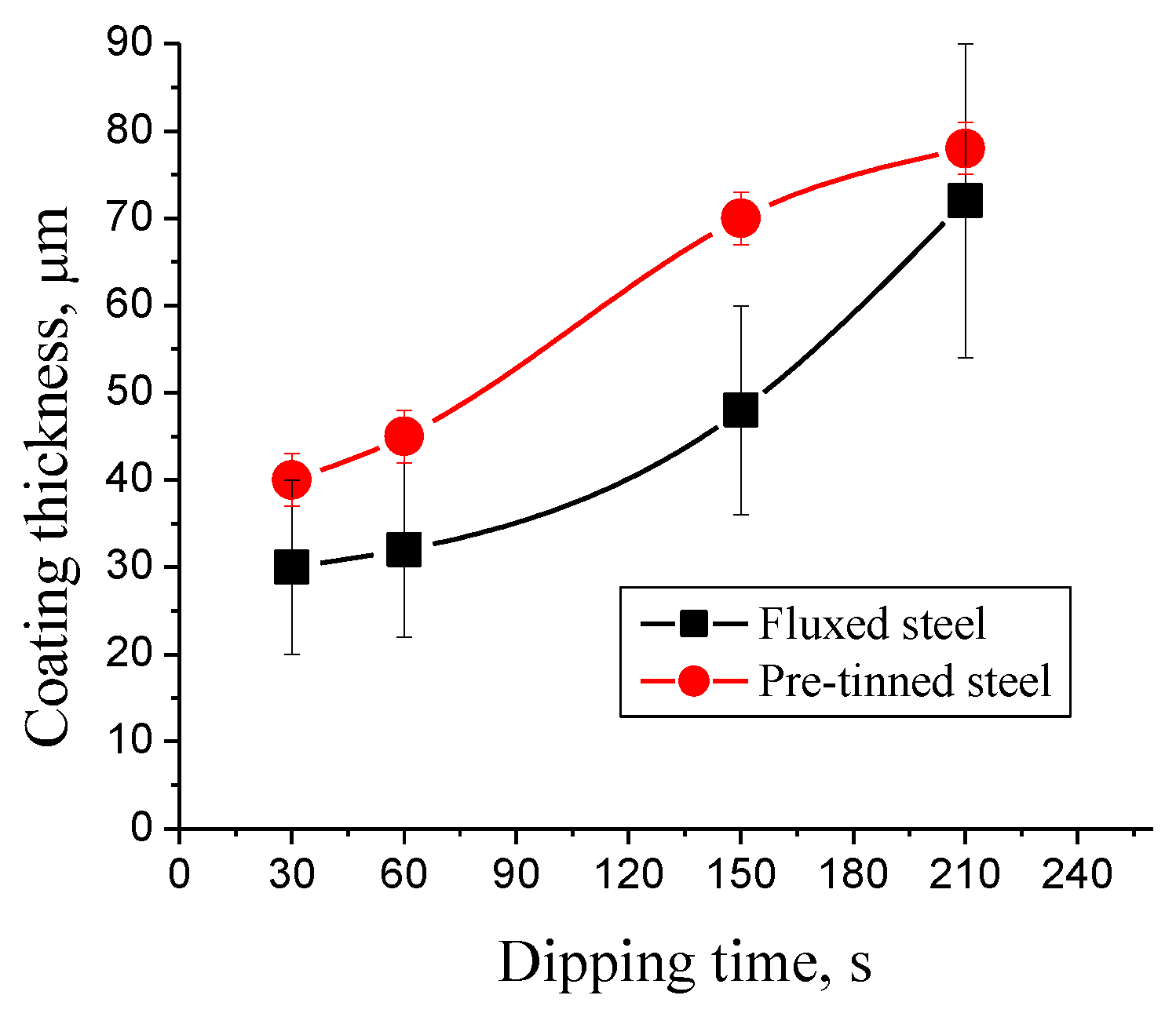
3.2. Mechanism of Tinning-Dipping Processes

The tinning-dipping process as a double coating process is complicated as it includes many possible chemical reactions between steel constituents and Sn/Al coating components. It should be clarified that the aim is to strengthen the mechanical bond between steel and coatings through formation of an isolated layer that can prevent any possible oxidation reactions during the hot-dipping process. It was found that the presence of Sn facilitates to great extent the formation of better interlayer bonds that enhance the transfer of Al coating via steel substrate [18,19,20,21,22,23]. However, the following possible chemical reactions might be expected during tinning-dipping (Al coating) of steel substrate:
Fe + 2Sn = FeSn2
2Fe + 5Al = Fe2Al5
Fe + 3Al = FeAl3
Fe + Al + Si = FeAlSi
In the pre-tinning process of Fe-Sn, an interfacial layer is formed that possibly contains FeSn2, FeSn, Fe3Sn2 and Fe6Sn3 phases. The main phase that their formation was confirmed in most previous literatures is FeSn2 that commonly observed in the interface of tinned steels products. However, this phase contains about 80% Sn and stable up to 496 °C. Accordingly, the FeSn2 phase will be dissolved directly during dipping of tinned steel in molten Al at temperature over 700 °C. Therefore, the interfacial layer possibly contains the products of reactions (2–4), these products are inevitable and greatly affect the characteristics of the interfacial layers of coatings, particularly the thickness of the intermetallic layer of coatings. Figure 5 handles the effect of dipping time on the thickness of the intermetallic layer, from which it can be reported that the effect of tinning on the thickness of the intermetallic layers are clear at short dipping times up to 2.5 min. However, the effect of tinning on the thickness of the intermetallic layers are insignificant in case of using a dipping time of 3.5 min. At dipping time up to 2.5 min, the thickness of tinned steel is a relatively lower compared with the fluxed steel one. Such fact can be explained as mentioned above in terms of the presence of FeSn2 phase hinder and/or delay the Al-Fe reaction during Al dipping at temperature above 700 °C.
The present study investigates in detail the formation of both interfacial and intermetallic layers of Al-coating using fluxed and tinned steel substrates. Figure 6, Figure 7, Figure 8, Figure 9 and Figure 10 show the SEM images of cross-sections and elemental mapping of dipping samples for fluxed and tinned steel substrates at different dipping times. As shown in Figure 6, the residuals flux can be detected in Fe-Al IMC layer for the fluxed samples (Figure 6a,c) while sound-homogenous layer of Fe-Al IMC can be observed in tinned samples (Figure 6b,d). The variation of thickness of IMC layer with dipping time can also be distinguished in tinned steel substrates (Figure 6b,d), as the thickness of the IMC layer increased by increasing dipping time.
The EDS analysis (Figure 7 and Figure 8) of fluxed samples dipped for 30 s in Al coatings shows the presence of Fe, Al and O which confirms the possibility of oxidation reactions for fluxed samples. The line scan of EDS analysis shows the un-intersect of the main components of expected interfacial layer (Fe, Al). Figure 8b shows line scan results across the interface of steel—Al alloy coating interface for steel with flux pre-treatment surface and dipping time of 30 s. An interface gap is clearly observed that could be explained by the presence of residual flux and an oxide phase in the interface layer.
On the other hand, the SEM/EDS analyses of the tinned steel substrates after dipping in Al coating alloy for 30 s confirm the previously mentioned mechanisms in which FeAl3 and Fe2Al5 are common IMCs phases observed after tinning-dipping processes. Figure 9 shows SEM image and EDS map elemental distributions of steel—Al alloy coating interface for steel with Sn pre-treatment surface and dipping time for 30 s. As detected in Figure 10, the EDS spectra and elements analysis of points 1 marked in Figure 9 shows an Sn atomic concentration (%) of about 0.12, which reduces the chance of the presence of FeSn2 phase as it dissolved in steel substrate during dipping process. So, it can be suggested that the interfacial layer is composed of FeAl3 and Fe2Al5 phases only.

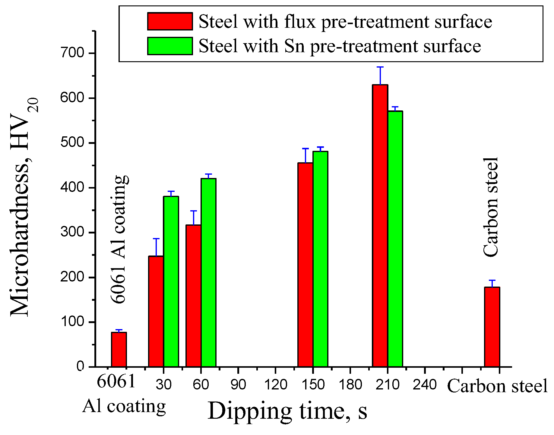
3.3. Interfacial Mechanical Properties

The dipping time plays an important role in the interface microhardness of both fluxed and tinned LCS after dipping in Al coatings (Figure 11). It can be observed that interfacial hardness for both pre-fluxed and pre-tinned steels were increased with increasing immersion time. As mentioned earlier, the thickness of the interfacial layer increased by increasing dipping time, and, accordingly, the hardness increased. The hardness of pre-tinning substrates is greater than that of fluxed ones for interfaces fabricated by immersion time up to 2.5 min. This can be attributed to the presence of residual flux and oxide phase in the interface layer of fluxed steel. Otherwise, the presence of a clear Sn interlayer in tinning samples enables the formation of regular and uniform interfacial layer between Al–Fe. The micro cracks can be developed between interfacial layers in the fluxed samples that can facilitate earlier failure, hence lowering microhardness. A relatively higher dipping time of 3.5 min resulted in disappearing the interface residual flux and other interface defects. Moreover, the presence of residual Sn in tinned steel could be a re-sound of decreasing hardness of the interface Fe–Al intermetallic layer in comparison with fluxed one.
In comparison of the results of the present work with that in the previous research, promising data was obtained in a very short dipping time when applying the tinning-aluminizing technique. The pervious study [3] investigated the effect of hot-dipped in Al and Al–Si alloys on the microstructure of the intermetallic layer for aluminide-coated mild steel. A thick Al-Fe intermetallic layer of about 120 µm and 100 µm was observed by hot dipping mild steel in Al and Al-0.5% Si alloy for 180 s. The IMC layer of aluminide steel dipped in molten Al-Si-Mg alloy was quite adherent to the steel substrate and capable of enduring bending and shock for dipping time of 180 s [1]. In the current research, applying tinning-aluminizing techniques as a double coating processes effect on rate and mechanism of Fe-Al intermetallic interface formation as well as increasing the thickness of homogenous coating layer over the steel substrate. The presence of Sn facilitates to great extent the formation of a thinner interface interlayer free of residual flux and/or oxides. Moreover, a good interface structure and a homogeneous coating surface layer were achieved by applying the tinning-aluminizing technique for very short time (30 s dipping time).

4. Conclusions

A novel route to protect low carbon steel from corrosion is suggested through double coating processes, including tinning and hot dipping of steel substrate in Al alloys. The double coating processes via tinning-aluminizing techniques are always accompanied by different phase transformations at the interface of coating layer and steel substrate, leads to formation of intermetallic compounds that greatly affects the adhesive strength and the formation of a mechanical bond between coatings and substrates. The presence of Sn facilitates to great extent the formation of a better interlayer bond that enhance the transfer of Al coating via steel substrate. Such kind of mechanism was confirmed throughout the present study via investigating microstructural changes accompanying tinning-dipping processes. The fluxed–dipped steel substrates have un-homogenous distribution of Al alloy coatings as well as the interface with residual flux and oxides for dipping time up to 2.5 min, while a homogenous distribution with good thickness morphology of the Al alloy coating and homogeneous thin intermetallic interface was achieved. The comparison between the pre-tinning and pre-fluxing processes of steel substrates shows a significant effect of tinning over fluxing treatment on the thickness layer of Al-coatings and interface using a short time dipping. The interface hardness for all steel substrates was increased with increasing dipping time due to increasing the thickness of the interfacial layer by increasing dipping time. For dipping time up to 2.5 min, the hardness of pre-tinning substrates is greater than that of fluxed ones due to the presence of residual flux and void interface in fluxed steel.

Author Contributions

Conceptualization, N.F., K.S.A.H. and M.R.; Data curation, N.F., K.M.H., A.S.A. and M.R.; Formal analysis, N.F., K.S.A.H., K.M.H., K.M.I. and M.R.; Investigation, K.M.H., B.A. and M.R.; Methodology, N.F., K.S.A.H., K.M.I. and M.R.; Project administration, M.R., A.S.A.; Software, K.M.H.; Writing—review & editing, K.S.A.H., N.F., A.S.A., K.M.I., B.A., N.F. and M.R. All authors have read and agreed to the published version of the manuscript.

Funding

This research has been funded by Scientific Research Deanship at University of Ha’il—Saudi Arabia through project number RG-21097.

Institutional Review Board Statement

Not applicable.

Informed Consent Statement

Not applicable.

Data Availability Statement

Not applicable.

Conflicts of Interest

The authors declare no conflict of interest.

References

  1. Dey, P.P.; Modak, P.; Banerjee, P.; Chakrabarti, D.; Seikh, A.H.; Abdo, H.S.; Luqman, M.; Ghosh, M. Studies on the characterization and morphological features of the coating on interstitial free steel dipped in molten Al-Si-Mg alloy at 800 °C. J. Mater. Res. Technol. 2020, 9, 4788–4805. [Google Scholar] [CrossRef]
  2. Cheng, W.-J.; Wang, C.-J. Observation of high-temperature phase transformation in the Si-modified aluminide coating on mild steel using EBSD. Mater. Charact. 2010, 61, 467–473. [Google Scholar] [CrossRef]
  3. Cheng, W.-J.; Wang, C.-J. Microstructural evolution of intermetallic layer in hot-dipped aluminide mild steel with silicon addition. Surf. Coat. Technol. 2011, 205, 4726–4731. [Google Scholar] [CrossRef]
  4. Chang, Y.Y.; Tsaur, C.C.; Rock, J.C. Rock. Microstructure studies of an aluminide coating on 9Cr-1Mo steel during high temperature oxidation. Surf. Coat. Technol. 2006, 200, 6588. [Google Scholar] [CrossRef]
  5. Wang, C.J.; Chen, S.M. The high-temperature oxidation behavior of hot-dipping Al–Si coating on low carbon steel. Surf. Coat. Technol. 2006, 200, 6601. [Google Scholar] [CrossRef]
  6. Richards, R.W.; Jones, R.D.; Clements, P.D.; Clarke, H. Metallurgy of continuous hot dip aluminizing. Int. Mater. Rev. 1994, 39, 191. [Google Scholar] [CrossRef]
  7. Khaliq, A.; Alghamdi, A.S.; Ramadan, M.; Subhani, T.; Rajhi, W.; Haider, W.; Hasan, M.M. Intermetallic compounds formation during 316L stainless steel reaction with Al–Zn–Si coating alloy. Crystals 2022, 12, 735. [Google Scholar] [CrossRef]
  8. Dey, P.P.; Modak, P.; Ghosh, A.; Chakrabarti, D.; Banerjee, P.; Ghosh, M. Investigation of phase evolution of Al–Si–Mg coating on hot dipped interstitial-free steel. Results Mater. 2020, 6, 100078. [Google Scholar] [CrossRef]
  9. Bahadur, A.; Mohanti, O.N. Aluminium diffusion coating on medium carbon steel. Mater. Trans. JIM 1995, 36, 1170–1175. [Google Scholar] [CrossRef] [Green Version]
  10. Cheng, W.J.; Wang, C.J. EBSD study of crystallographic identification on Fe-Al-Si intermetallic phases in aluminide coatings on mild steels. Adv. Mater. Res. 2009, 79–82, 907–910. [Google Scholar] [CrossRef]
  11. Ramadan, M.; Alghamdi, A.; Hafez, K.; Subhani, T.; Halim, K.A. Development and optimization of tin/flux mixture for direct tinning and interfacial bonding in aluminum/steel bimetallic compound casting. Materials 2020, 13, 5642. [Google Scholar] [CrossRef] [PubMed]
  12. Ramadan, M.; Alghamdi, A.S.; Subhani, T.; Halim, K.S.A. Fabrication and characterization of Sn-based babbitt alloy nanocomposite reinforced with Al2O3 nanoparticles/carbon steel bimetallic material. Materials 2020, 13, 2759. [Google Scholar] [CrossRef]
  13. Ramadan, M.; Hafez, K.M.; Alghamdi, A.S.; Ayadi, B.; Halim, K.S.A. Correction to: Novel approach for using ductile iron as substrate in bimetallic materials for higher interfacial bonding bearings. Int. J. Met. 2021, 16, 1001. [Google Scholar] [CrossRef]
  14. Alghamdi, A.S.; Halim, K.S.A.; Amin, M.A.; Alshammari, A.S.; Fathy, N.; Ramadan, M. Interfacial microstructure and corrosion behaviour of mild steel coated with alumina nanoparticles doped tin composite via direct tinning route. Coatings 2021, 11, 1318. [Google Scholar] [CrossRef]
  15. Halim, K.S.A.; Ramadan, M.; Sherif, E.-S.M.; Hafez, K.M.; Subhani, T.; Fathy, N.; Alghamdi, A.S.; Khedr, M.H. Enhancement of surface and interface properties of low carbon steel by hybrid ZnO and NiO nanoparticles reinforced tin coating. Crystals 2022, 12, 332. [Google Scholar] [CrossRef]
  16. Wang, H.; Zhu, Y.; Hu, Z.; Zhang, X.; Wu, S.; Wang, R.; Zhu, Y. A novel electrodeposition route for fabrication of the superhydrophobic surface with unique self-cleaning, mechanical abrasion and corrosion resistance properties. Chem. Eng. J. 2016, 303, 37–47. [Google Scholar] [CrossRef] [Green Version]
  17. Huang, J.; Lou, C.; Xu, D.; Lu, X.; Xin, Z.; Zhou, C. Cardanol-based polybenzoxazine superhydrophobic coating with improved corrosion resistance on mild steel. Prog. Org. Coat. 2019, 136, 105191. [Google Scholar] [CrossRef]
  18. Gines, J.L.; Benítez, G.J.; Egli, W.; Zubimendi, J.L.; Pérez, T. Formation of an Fe–Sn intermetallic layer during the reflow, process after tin plating. Plat. Surf. Finish. 2003, 90, 44–49. [Google Scholar]
  19. Kumar, K.; Wollants, P.; Delaey, L. Thermodynamic evaluation of Fe–Sn phase diagram. Calphad 1996, 20, 139–149. [Google Scholar] [CrossRef]
  20. Ramadan, M.; Khaliq, A.; Hafez, K.M.; Alghamdi, A.S.; Fathy, N.; Harraz, F.A.; Ayadi, B.; Halim, K.S.A. Super bonding strength of Al2O3 nanoparticles reinforced Sn interlayer steel/aluminum bimetal casting. Crystals 2022, 12, 324. [Google Scholar] [CrossRef]
  21. Durandet, Y.; Strezov, L.; Ebrill, N. Formation of Al–Zn–Si coatings on low carbon steel substrates. Galvatech 1998, 98, 147–152. [Google Scholar]
  22. Raghavan, V. Al–Fe–Si (aluminum–iron–silicon). J. Phase Equilibria 2002, 23, 184–188. [Google Scholar] [CrossRef]
  23. Dionisio, P.H.; de Barros, B.A.S., Jr.; Baumvol, I.J.R. Intermetallic phases formed during tin implantation into iron and steels. J. Appl. Phys. 1984, 55, 4219–4224. [Google Scholar] [CrossRef]
Figure 1. Optical microstructure of (a) carbon steel substrate and (b) initial microstructure of pre-tinned steel before dipping process.
Coatings 12 01499 g001
Figure 2. Cross-section microstructures of steel with Al alloy coating; (a) steel with flux pre-treatment surface and dipping time for 30 s; (b) steel with Sn pre-treatment surface and dipping time for 30 s, (c) steel with flux pre-treatment surface and dipping time for 150 s; (d) steel with Sn pre-treatment surface and dipping time for 150 s.
Coatings 12 01499 g002
Figure 3. Cross-section microstructures of steel with Al alloy coating; (a) steel with flux pre-treatment surface and dipping time for 60 s; (b) steel with Sn pre-treatment surface and dipping time for 60 s, (c) steel with flux pre-treatment surface and dipping time for 210 s; (d) steel with Sn pre-treatment surface and dipping time for 210 s.
Coatings 12 01499 g003
Figure 4. Effect of dipping time on thickness of Al alloy surface layer of fluxed and pre-tinned steels.
Coatings 12 01499 g004
Figure 5. Effect of dipping time on thickness of Fe–Sn IMC interface coatings fluxed and pre-tinned steel.
Coatings 12 01499 g005
Figure 6. SEM images of cross-section of steel with Al alloy coating; (a) steel with flux pre-treatment surface and dipping time for 30 s; (b) steel with Sn pre-treatment surface and dipping time for 30 s, (c) steel with flux pre-treatment surface and dipping time for 150 s; (d) steel with Sn pre-treatment surface and dipping time for 150 s.
Coatings 12 01499 g006
Figure 7. SEM image and EDS map elemental distributions of steel—Al alloy coating interface for steel with flux pre-treatment surface and dipping time for 30 s, (a) SEM image, (b) O map, (c) Fe map, (d) Al map.
Coatings 12 01499 g007
Figure 8. (a) SEM image of the cross-section of steel—Al alloy coating interface for steel with flux pre-treatment surface and dipping time of 30 s; (b) line scan results across the interface.
Coatings 12 01499 g008
Figure 9. SEM image and EDS map elemental distributions of steel—Al alloy coating interface for steel with Sn pre-treatment surface and dipping time of 30 s, (a) SEM image, (b) Sn map, (c) Fe map, (d) Al map.
Coatings 12 01499 g009
Figure 10. EDS spectra and elements analysis of points 1 marked in Figure 9a.
Coatings 12 01499 g010
Figure 11. Interfacial hardness as a function of dipping time of steel—Al alloy coating for steel with flux and Sn pre-treatment surfaces.
Coatings 12 01499 g011
Table 1. Chemical composition of carbon steel substrate and 6061 aluminum coating alloy, wt. %.
CSiMnCuCrMgFeAl
Steel substrate0.140.300.430.200.12-Bal.-
6061 Aluminum coating alloy-0.720.100.200.051.010.53Bal.
Publisher’s Note: MDPI stays neutral with regard to jurisdictional claims in published maps and institutional affiliations.

