Abstract
In this study, an extended layerwise/solid-element (XLW/SE) method is developed for the thermo–chemo–mechanical (TCM) coupling problem of an aero-engine turbine blade with thermal barrier coatings (TBCs). The method consists of two parts, the extended layerwise (XLW) method and the three-dimensional (3D) solid-element (SE) method, which are adopted to formulate the governing equations of TBCs and substrate, respectively. Then, according to the compatibility conditions of displacement, temperature, concentration and internal force equilibrium at the TBCs/substrate interface, the governing equation of the final blade structure is assembled. Through a time integration, the dynamic responses of displacement, temperature and concentration can be calculated. In addition, the fluid–structure coupling analysis is conducted by using COMSOL. The nonuniform thermal load is imported into the XLW/SE method to calculate the mechanical response of blade structure. Finally, the corresponding computing program is compiled with C++. In numerical examples, the TCM coupling analysis is conducted on the blade structure with and without interfacial debonding and delamination damages. To validate the effectiveness of the proposed method, the dynamic TCM responses of the XLW/SE model is compared with those of a 3D elastic model generated by COMSOL, which shows that the two models are in good agreement.
1. Introduction
With the increasing output power of gas turbine and the increasing weight ratio of aircraft engine, the turbine inlet temperature is greatly improved. How to ensure the safe operation of aero-engine turbine blades under a high-temperature, high-pressure, oxidation and corrosion environment has long been the major focus in the field of aircraft engineering. In response to this problem, a variety of technologies have been adopted, for example, the blade casting technology [1] for improving the blade temperature resistance, the film cooling technology [2,3,4,5,6,7] with real-time cooling and thermal protection system and the TBCs technology with low thermal conductivity and high stability [8,9].
As a multilayer structure, TBCs can effectively reduce the substrate temperature, and maintain the machinability and reliability of the alloy substrate. The cross-sectional view of TBCs structure is shown in Figure 1 [10]. The substrate is composed of nickel-based or cobalt-based superalloys with sufficient mechanical strength. The TBCs consist of two parts: a ceramic coat and a bond coat. The ceramic coat is composed of and (YSZ). Its outstanding thermal insulation performance can protect the substrate from oxidation, corrosion and erosion. The bond coat is an antioxidation layer composed of NiCrAlY or NiCoCrAlY alloy. It is used to firmly adhere the ceramic coat to the substrate, so as to reduce the mismatch stress caused by the different thermal expansion coefficients of the ceramic coat and substrate.
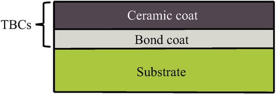
Figure 1.
Cross-sectional view of a structure with TBCs [10].
The aero-engine turbine blade with TBCs is commonly used in a multiphysics environment. The variations of service environment may affect the life cycle of the turbine blade. In recent years, several studies have been devoted to the multi-physics coupling analysis of TBCs structure. For instance, Liu et al. [11] simulated the thermal stress of a turbine blade with TBCs under the conditions of air film cooling and thermally grown oxide (TGO). Wang et al. [12] simulated the thermal insulation of a turbine blade with TBCs in a cascade flow field. Zhou and Hashida [13] analyzed the thermal stress fields in TBCs, considering the coupled effects of temperature gradient and oxidation. Zhang et al. [14] studied the effect of Cr and Co oxides on TGO growth at 1000 °C. The thermodynamics and kinetics of oxidation were analyzed.
Some studies have focused on the effects of various damage forms on TBCs structure [15,16,17,18,19,20]. For instance, Xiao et al. [21] developed a phase-field damage model to quantify the cumulative damage, crack nucleation, propagation and coalescence, and they also analyzed the impact of thermal cycling and growth stresses on the TBCs structure. Li and Shan [22] performed a TCM coupling analysis of TBCs structure with multiple interface and transverse cracks; however, they ignored the impacts of the metal substrate on the TBCs structure.
The multiphysics coupling problem of TBCs fracture is still the bottleneck of turbine blade design, optimization and production. The XLW method can be used as an efficient tool to address this problem. For instance, Li et al. [23,24,25,26,27,28,29] analyzed the layered damage and transverse cracks of composite laminates by using the XLW method, which achieved a higher accuracy and less computation compared with the 3D elastic model. In the finite-element governing equation, the degrees of freedom (DOFs) for the upper and lower surfaces of the shell-like structures can be adjusted. This facilitates the combination of the XLW method with other methods according to the compatibility conditions of TBCs/substrate interface [30,31,32,33,34,35,36,37]. Li [38,39] developed a steady-state and dynamic thermo–mechanical XLW method for the laminated composite plates with multiple delaminations and transverse cracks. A similar study by Li and Shan [40] developed a chemo–mechanical XLW method for the multilayered porous media with different damage forms.
Based on the above review, most studies focused on the fracture analysis of coatings only. Some studies considered both the TBC and the substrate but simplified the structure as a 2D problem and did not approach the complex curved surface structure of the actual blade. Furthermore, the geometric dimensions of the coatings and blade differ greatly, which is a cross-scale problem. Hence, using traditional solid element to construct the grids increases the grid number and computation, which also increases the complexity of the finite element analysis. In addition, the real temperature field, which has to be determined by a thermal fluid–structure coupling analysis, was not subject to the existing fracture analysis model. Therefore, according to the existing research, this study proposes a computational framework for an aero-engine turbine with TBCs and develops the corresponding computing program. This method can simultaneously apply two methods for cross-scale modeling, and without any additional geometric assumptions. Moreover, the method can be used for a thermo–chemo–mechanical and fluid–structure coupling analysis of complex structures with damage, while ensuring the accuracy of the analysis. This is difficult for other methods to achieve, and the proposed damage analysis model can be used for a complex structure, rather than a simple plate and circular structures.
The rest of the paper is organized as follows. Section 2 introduces the TCM variational theorem. The TCM formulations for the substrate are defined by using SE method. In Section 3, the functionally gradient material (FGM) structure of TBCs is described. The coatings with delamination and transverse cracks is modeled by using the XLW method. In Section 4, the XLW/SE method for the TCM coupling analysis is presented. The governing equation of a turbine blade with TBCs is assembled. Then, a mixed semidiscretization method is applied to calculate thermal, chemical and mechanical responses. In Section 5, a fluid–structure coupling analysis is conducted to solve the flow field of the turbine blade. In Section 6, the flowchart of the computing program for the TCM and fluid–structure coupling analyses is presented. In Section 7, the numerical examples are given to verify the convergence and accuracy of the proposed XLW/SE method. Finally, a conclusion and future work are given in Section 8.
2. Thermo–Chemo–Mechanical Solid-Element Method for Substrate Structure
2.1. Thermo–Chemo–Mechanical Variational Theorem
According to the Hamilton principle, the energy forms of mechanical, chemical and thermal fields are considered in this study. The TCM mixed variational principle for the present solution domain is given by
The boundary conditions are expressed as
In Equation (1), the first row represents the energy generated by the mechanical field. and denote the mechanical strain and mechanical stress, respectively. denotes the displacement component in the x, y, z directions, respectively. denotes the imposed displacement on boundary . and denote the mechanical body force and mechanical surface force on boundary , respectively. denotes the mass density.
The second row represents the energy generated by the thermal field. , and denote temperature change, temperature gradient and positive reference temperature, respectively. denotes the heat flux vector, and ℏ denotes the heat flux on boundary . , and denote the heat source, entropy density change rate and imposed temperature change on boundary , respectively.
The third row represents the energy generated by the chemical field. c denotes the chemical ion concentration, and denotes the imposed concentration on boundary . denotes the mass flux vector, and denotes the mass flux on boundary . , and denote the chemical potential change rate, penalty factor and chemical ion concentration gradient, respectively. and denote the outward unit normal vectors.
2.2. Solid-Element Method for Thermo–Chemo–Mechanical Coupling Problem of Substrate Structure
The SE method is adopted to solve the 3D dynamic TCM coupling problems of the substrate structure. The displacement , temperature change and chemical ion concentration c can be expressed as
where denotes the number of nodes per element. As the isoparametric elements were employed, in this study. denotes the shape function. The gradient relations of strain , temperature gradient and chemical gradient components corresponding to , and c are, respectively, defined as
Based on the linear constitutive law for the TCM problem, the constitutive equations of mechanical stress , entropy density , chemical potential , heat flux and mass flux are given by
where and denote the thermal expansion coefficient and thermal stress–temperature coefficient, respectively. , where denotes the specific heat capacity. , and denote the stiffness, thermo–chemical coefficient and chemo–thermal coefficient, respectively. k, and denote the chemical potential constant, heat conduction coefficient and mechanical–chemical coefficient, respectively. denotes the diffusion coefficient of anions and cations. Based on Equations (1) and (3), the finite formulations of the TCM coupling problem can be derived as
where , and denote the mass, damping and stiffness matrices, respectively. and denote the velocity and acceleration vectors, respectively. and denote the temperature and chemical concentration change rates, respectively. , and denote the mechanical, thermal and chemical load vectors, respectively. The submatrix of each aforementioned element is expressed as
where denotes the strain–displacement matrix per finite element, which is expressed as
3. Thermo–Chemo–Mechanical Extended Layerwise Method for TBCs Structure
3.1. Functionally Gradient Material Structure
In TBCs, the bond coat is used as a transition layer to reduce the difference of thermal expansion coefficient between the metal substrate and the ceramic coat. Nevertheless, such structure yields a large thermal stress and residual stress during service, thus greatly shortening its life cycle. A TBCs structure with the gradient composition ratio, as shown in Figure 2, can eliminate the macroscopic interface and reduce the residual stress and thermal stress. For the FGM structure, the volume fractions of ceramic coat and bond coat are expressed as
where n denotes the gradient index. h denotes the thickness of the FGM structure. z denotes the coordinate in the layer thickness direction, ranging from to . In Figure 2, the top surface is pure ceramic coating (i.e., , , ), while the bottom surface is pure bond coating (i.e., , , ). The middle part is the functionally graded structure composed of ceramic and bond materials.

Figure 2.
FGM structure of TBCs.
The material properties of the FGM structure change in gradient along the layer thickness direction. Based on Equation (12), the material property is expressed as
where denotes the material property parameter and is the function of z. and are the material property parameters of the top and bottom surfaces, respectively.
3.2. Thermo–Chemo–Mechanical Extended Layerwise Method of TBCs Structure
The XLW method transforms the 3D fracture problem into a one-dimensional fracture problem in the z direction and a two-dimensional fracture problem in the x and y directions. The linear Lagrange interpolation function is used to model the dynamic displacement, temperature change and chemical ion concentration of TBCs with multiple delaminations. As shown in Figure 3 [29], in the z direction, the interpolation nodes are located at the bottom and top surfaces of TBCs and the middle surface of each mathematical layer. The displacement , temperature change and concentration c at point can be discretized as
where is the linear Lagrange interpolation function. is the shape function for modeling displacement discontinuities caused by delaminations. is the shape function for modeling strain discontinuities caused by interlaminar interfaces. k is the layer number, and N is the total number of mathematical layers. is the number of nodes. , and are the standard nodal DOF, the additional nodal DOF for displacement discontinuities and the additional nodal DOF for strain discontinuities, respectively. i, l and r are the corresponding subscripts, and are the x, y and z directions, respectively. (, , ) and (, , ) are the nodal DOFs of chemical and temperature fields, respectively.
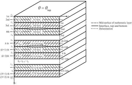
Figure 3.
TBCs structure with multiple delaminations.
For the TBCs with transverse cracks in the x and y directions, the in-plane nodal displacement , temperature change and concentration can be discretized as
where denotes the two-dimensional Lagrange interpolation function. denotes the shape function for modeling the in-plane transverse cracks. denotes the shape function for modeling the in-plane transverse crack tips. , and are the standard nodal DOFs. , and are the additional nodal DOFs yielded from the in-plane transverse cracks. , and are the additional nodal DOFs yielded from the in-plane transverse crack tips. = i, l, r.
Based on Equations (1), (14) and (15), the finite-element governing equation for the dynamic TCM-XLW method is expressed as
The stiffness matrix , mass matrix and damping matrix are given by
Note that and , where , and is the number of in-plane element nodes. and , where and are the numbers of in-plane nodes enriched by the transverse crack discontinuities and the transverse crack tips, respectively. , and denotes the number of the crack-tip enrichment functions. The values of index pairs , and are related to the shape functions , and , respectively. In Equation (16), can be obtained by replacing the shape function corresponding to p and q. Other submatrices of the element stiffness, mass and damping matrices can be obtained in a similar way. The detailed expressions of the above submatrices are listed in Appendix A.
3.3. Transformation of Coordinate System
The element stiffness matrix in the local coordinate system was derived in the previous subsection. For the complexity of the turbine blade surface, the coordinate systems needs to be modified. Figure 4 displays the global coordinate system and local coordinate system of finite elements. In this study, , and are the three directions of the global coordinate system. x, y and z denote the three directions of the local coordinate system. Note that x and are parallel to each other.
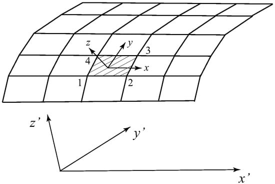
Figure 4.
Global coordinate system and local coordinate system of finite elements.
In two coordinate systems, the nodal displacement vectors are expressed as
The transformation equations of two coordinate systems and the transformation matrix are given by
where is the cosine of the local nodal coordinates in x, y and z directions of the global coordinate system. For instance, in Figure 4, the local nodal coordinates of Node 1 and Node 4 are and . The global nodal coordinates are and . The direction cosines , and are, respectively, expressed as
and
where is the distance between two nodes. By following the above method, the element stiffness matrix and load vector in the global coordinate system can be transformed from the element stiffness matrix and load vector in the local coordinate system. The transformation equations are given by
where the transformation matrix is expressed as
Based on the above, the governing equation of the overall structure can be obtained. According to the nodal displacement vectors and in the two coordinate systems, the element stress can be calculated, which satisfies the following functional relationship
and the projection of the local coordinate system on the global coordinate system is
where denotes the angle between two basis vectors and .
4. Extended-Layerwise/Solid-Element Method for Aero-Engine Turbine Blade with TBCs
4.1. Modeling of Aero-Engine Turbine Blade with TBCs
The aero-engine turbine blade is a complex structure, as shown in Figure 5. The curvature and thickness of the blade are not fixed values at different positions. Moreover, the thickness difference between the TBCs and the substrate may increase the complexity of the finite-element modeling. To satisfy the actual condition, the proposed XLW/SE method was adopted to solve the dynamic TCM coupling problem of the turbine blade with TBCs. The thickness of the FGM structure was 150 . The cooling air-film holes of the blade were also considered.
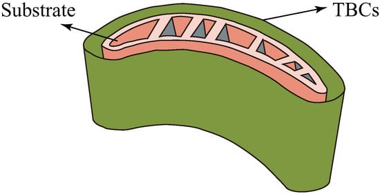
Figure 5.
Aero-engine turbine blade with TBCs.
4.2. Governing Equations of Aero-Engine Turbine Blade with TBCs
In this section, the governing equations of the TBCs and the substrate for the turbine blade are formulated. In order to ensure the compatibility of nodes and elements on the TBCs/substrate interface, the compatibility conditions of displacement, temperature and concentration at the interface are defined, as shown in Figure 6. The meshing of the TBCs is based on the outward free surface of the substrate. Finally, the governing equation of the overall blade structure is assembled.

Figure 6.
Compatibility conditions of TCM coupling problem for the aero-engine turbine blade with TBCs.
With respect to the TBCs structure, the displacement, temperature and concentration DOFs can be divided into two parts: (i) the external DOFs of the TBCs/substrate interface and (ii) the internal DOFS of the TBCs structure excluding the interface. Referring to the governing equation for the TCM-XLW method in Equation (16), the governing equation of TBCs is given by
where P represents TBCs. The subscripts 1 and 2 are the external and internal DOFs, respectively. The subscripts 12 and 21 denote the coupling of external and internal DOFs. and denote the mechanical–thermal coupling and mechanical–chemical coupling. , and denote the stiffness, damping and mass matrices, respectively. and denote the external and internal displacement vectors. and denote the velocity vectors. and denote the acceleration vectors. and denote the internal interaction force and mechanical external load vector. and denote the thermal external load and thermal interaction force. and denote the chemical external load and chemical interaction force.
With respect to the substrate structure, the displacements, temperature and concentration DOFs can also be divided into two parts: (i) the external DOFs of the TBCs/substrate interface and (ii) the internal DOFs of the substrate excluding the interface. The governing equation of the substrate is given by
where s represents the substrate. The compatibility conditions of displacement, temperature, concentration and interface force equilibrium at the TBCs/substrate interface are given by
In Equations (28) and (29), the summation of the first rows is calculated as
The summation of the third rows is calculated as
The summation of the fifth rows is calculated as
Based on the above, Equations (31) to (33), and the second, fourth and sixth rows of Equations (28) and (29), the final governing equation of the overall structure (i.e., substrate and TBCs) is assembled as
where the submatrices of stiffness, damping, mass and the vector matrices of displacement, acceleration and load are as follows
4.3. Time Integration of Thermo–Chemo–Mechanical Responses
Referring to the Newmark and Crank–Nicolson integration method, a mixed semidiscretization method was developed to calculate the dynamic TCM responses of blade structure at each time step . The responses including temperature change , concentration , velocity and displacement at time are given by
where , and are the coefficients that determine the numerical stability and accuracy. In this study, the value of was set to 0.5 to ensure the unconditional stability without numerical dissipation. The values of and were set to 0.5 and 0.25 to ensure the numerical stability. The derivatives of the aforementioned responses are expressed as
where , , , , , , , , , . Based on the above, Equation (34) at time can be rewritten as
Substituting Equation (37) into (38), we have
where
5. Fluid-Structure Analysis for Aero-Engine Turbine Blade with Cooling Structure
Gas turbine blades are continuously impacted by high-temperature and high-pressure gases in the actual working condition. An efficient cooling method is needed to reduce the blade temperature and ensure its strength and service life. The film cooling technology is commonly used in turbine blade structure, which has multiple cooling holes and an internal cooling chamber, as shown in Figure 7 [41]. In working state, the cooling gas flows through the internal passage to cool the blades from inside. Then, the cooling gas flows through the cooling holes and mixes with the external high temperature gases to reduce the wall temperature of turbine blades.
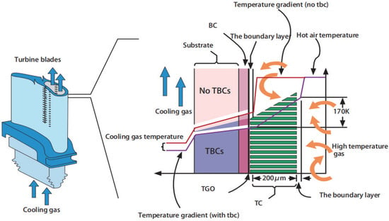
Figure 7.
Schematic diagram of turbine blade with cooling structure and thermal barrier coating [41].
The temperature change may result in a large thermal stress in the solid interior of turbine blades. This is the main reason for blade creep, fatigue and other forms of damage, which directly affect the safety and stability of aero-engine operation. Therefore, it is necessary to obtain an accurate thermal load distribution of turbine blades with the cooling structure and TBCs.
In this study, the Reynolds-averaged Naiver–Stokes (RANS) equations were used to solve the flow field. Since the major form of gas flow in an aero-engine turbine is turbulence, the shear stress transfer (SST) model was used as the turbulence model to complete the RANS equations and simulate the motion state of turbulence. The SST model was developed by combining the and models, which had fewer grids and better adaptability. The differential form of the governing equations for an unsteady fluid was expressed as
where , and are the momentum source term, energy source term and total specific enthalpy, respectively. , and are the fluid velocity, pressure and density, respectively. is the dynamic viscosity.
6. Computational Framework of Extended-Layerwise/Solid-Element Method
To implement the proposed computational framework, the corresponding computing program was compiled by using C++. Figure 8 presents the flowchart of the computational process, which can be divided into four steps. Details of each step are described as follows.
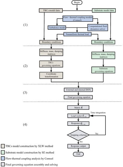
Figure 8.
Flowchart of computational procedure.
(1) The models of TBCs and substrate are input into the XLW/SE method to start the program. For each model, the boundary conditions of temperature, concentration and displacement are defined. For the flow–thermal coupling problem, the SST model based on the RANS method is used as the turbulence model. By using the fluid dynamics solver provided by COMSOL, the nonuniform thermal load is obtained and then input into the XLW/SE method to calculate the mechanical response of blade structure.
(2) By following the SE method for the substrate described in Section 2 and the XLW method for TBCs from Section 3, the stiffness, mass and damping matrices of the substrate and TBCs are formulated, and then used to formulate their governing equations, respectively.
(3) By following the XLW/SE method from Section 4, the displacement, temperature and concentration DOFs are determined. The governing equation of the overall structure is assembled.
(4) The iteration of the time integration is performed. Referring to Equation (40), the equivalent stiffness matrix and load vector are calculated. Then, referring to Equation (39), the responses of temperature, concentration and displacement at time are calculated. The iteration is stopped when the stopping criterion is satisfied.
7. Numerical Examples
7.1. Validation of Extended-Layerwise/Solid-Element Method
To verify the convergence and accuracy of the proposed XLW/SE method, an aero-engine turbine blade with TBCs was used in the numerical examples, which was subjected to thermal and chemical loads. Each layer of the model was isotropic, and the boundary condition was bottom clamped. The outermost wall temperature was 800 K, and the chemical icon concentration was 80 . The initial temperature and concentration were 0 K and 0 , respectively. The TBCs and substrate material parameters that characterized the chemical, thermal and mechanical properties are listed in Table 1. The functional gradient index n was 0.5.

Table 1.
TCM Parameters of TBCs and substrate.
To begin, the convergence of the meshing scheme and time step should be analyzed. In this numerical example, the time step and three different meshing schemes were adopted, as shown in Figure 9. The numbers of elements and nodes for each meshing scheme are listed in Table 2. A random point A (16.0 cm, −12.2 cm, 0.28 cm) located inside the blade structure was selected. Its dynamic responses of displacement , and in the x, y and z directions are, respectively, shown in Figure 10. It can be observed that the displacement curves gradually converge with time, and the convergence trends of the three meshing schemes are consistent. Since the curves of the second and third meshing schemes coincide, it can be confirmed that the second meshing scheme is convergent.

Figure 9.
Three different meshing schemes of turbine blade.

Table 2.
Number of elements and nodes for three different meshing schemes.
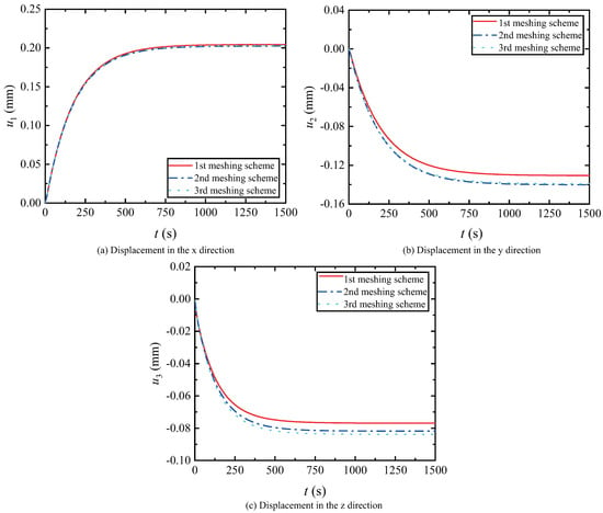
Figure 10.
Displacements for three different meshing schemes.
For the second meshing scheme, the displacement curves of three different time steps are presented Figure 11 shows. It can be observed that when , the displacement curve shows a convergent trend and can provide the convergence result. Therefore, the second meshing scheme with the time step is employed in the following cases; see the numerical examples below.
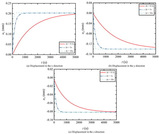
Figure 11.
Displacements for three different time steps.
To validate the effectiveness of the proposed XLW/SE method, a 3D elastic model developed in COMSOL 5.6 was compared with the XLW/SE model. Firstly, by following the SE method from Section 2 and the XLW method from Section 3, the 3D models of the substrate and TBCs were simulated, respectively. Then, by following the XLW/SE method from Section 4, the responses of displacement, temperature and concentration of point A were obtained. Comparing the response curves and maximum displacement of the XLW/ME model with those of the 3D elastic model, as shown in Figure 12 and Table 3. The corresponding nephograms at 250 s and 1000 s are presented in Figure 13.
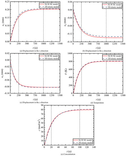
Figure 12.
Displacement, temperature and concentration for TBCs structure.

Table 3.
Maximum displacements of the 3D elastic model and XLW/SE model.
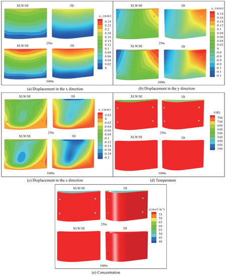
Figure 13.
Nephograms of TCM responses of nondestructive TBCs structure by using XLW/SE method and COMSOL finite element software.
7.2. TBCs with Debonding at Interface
The spalling of TBC during service results in the generation of a debonding area and even the failure of the TBC system. This section simulates the effect of TBC debonding on TCM responses (i.e., displacement, temperature and concentration distribution) in the layer thickness direction. The working conditions of the blade structure were the same as those in the previous section. Since the material of TBCs was functionally graded, the top layer and bottom layer were pure and NiCoCrAlY, respectively. Two cases were considered: (i) Case 1: aero-engine turbine blade without debonding at the interface; (ii) Case 2: aero-engine turbine blade with debonding at the interface. The interface between the coating and substrate can exhibit debonding damage, as shown in Figure 14.
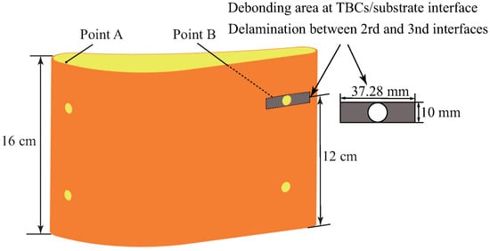
Figure 14.
TBCs structure with debonding and delamination.
A random point B (12.0 cm, 7.3 cm and 3.8 cm) on the substrate behind the damaged area was selected, and its dynamic responses of displacement, temperature and concentration are shown in Figure 15. The results show that the presence of a debonding crack affects the normal conduction of temperature and concentration and prolongs the time for the temperature and concentration to reach stability. Meanwhile, the existence of the debonding has a significant impact on the displacement changes in all the directions of point B. In Figure 15, the displacement curves of two cases are basically coincident at the beginning. However, due to the existence of interfacial debonding, a difference of displacement between the two cases gradually appears, and the steady-state value of displacement for the blade with debonding is lower than that without damage. However, the interface debonding has a significant effect on the transient value of temperature change and concentration, but no influence on the steady-state value.
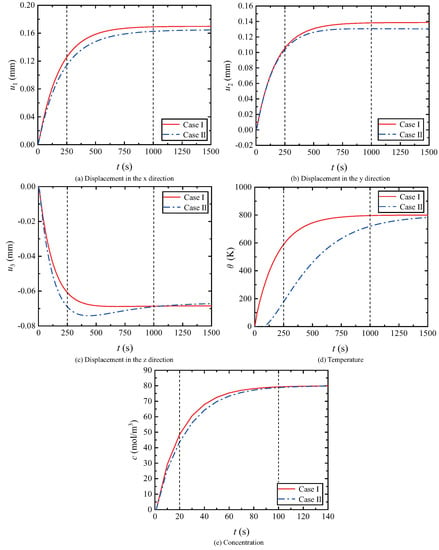
Figure 15.
Displacement, temperature and concentration for TBCs structure with debonding at interface.
7.3. TBCs with Delamination and Interfacial Debonding
In the complex service environment, delamination and interfacial debonding cracks often occur simultaneously in TBCs with functionally graded structure. This complex damage problem was considered and the aforementioned thermal barrier coatings structure was employed. Three cases were considered: (i) Case 1: the turbine blade without damage; (ii) Case 2: the turbine blade with debonding; (iii) Case 3: the turbine blade with delamination and interfacial debonding. The delamination at the interface between the 2nd and 3rd layers of TBCs and the size of the delamination area were the same as in the previous example, as shown in Figure 14.
At point B, the dynamic responses of displacement, temperature and concentration are shown in Figure 16. The corresponding nephograms of the TCM responses at 250 s and 1000 s are presented in Figure 17. By comparing Case 1 and Case 3, it is found that the delamination prevents the conduction of temperature and concentration, leading to a delay for the response curves to stabilize, and the displacement amplitude is smaller than that of Case 1. By comparing Case 2 and Case 3, it can be found that there are differences in the time-varying curves of , and at Point B, and this difference is gradually increasing with time. At the same time, the temperature and concentration response curves are also further affected, and the conduction process becomes slower, which is caused by the combined effect of delamination and debonding. The delamination has a significant effect on the transient value of the temperature change and concentration, but no influence on the steady-state value.
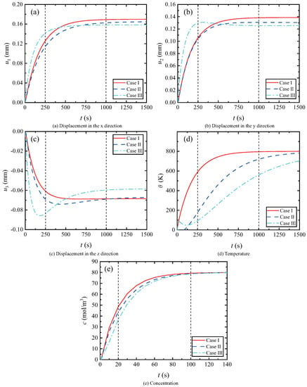
Figure 16.
Displacement, temperature and concentration for TBCs structure with debonding and delamination.
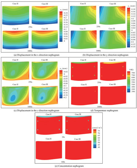
Figure 17.
Nephograms of TCM responses in Case 2 and Case 3.
7.4. Coupling Analysis of Thermo–Chemo–Mechanical Field and Fluid-Structure Interaction
To ensure the structural stability of the turbine blade in a high-temperature environment, the gas-film holes and the internal cooling cavities can effectively reduce heat transfer. Moreover, in the flow field environment, when the gas-film cooling jet encounters the high-temperature and high-speed gas, a complex nonuniform temperature field is formed. This section conducts the coupling analysis of the TCM field and fluid–structure interaction of the turbine blade with the cooling structure. For this, we used another local turbine blade model with TBCs, whose geometric model and mesh model are shown in Figure 18. Firstly, commercial finite element software was used to calculate the flow–thermal coupling. The temperature of the outer mainstream gas was 1550 K, and the airflow velocity was 128 m/s. The temperature of the inner cold airflow was 850 K, and the airflow velocity was 106 m/s. The surface of the model structure, the inner flow channel wall and the inner wall interface of the film hole were nonslip walls, and the external flow field was set as periodic boundary conditions. An SST turbulence model was adopted for the turbulence model, and a turbulence intensity of 0.05 was selected. Only the internal cold airflow was considered to be mixed with the external mainstream gas through the cooling hole of the turbine blade. The nonuniform wall temperature load calculated by commercial software was introduced into the XLW/SE method to further calculate and analyze turbine blades.
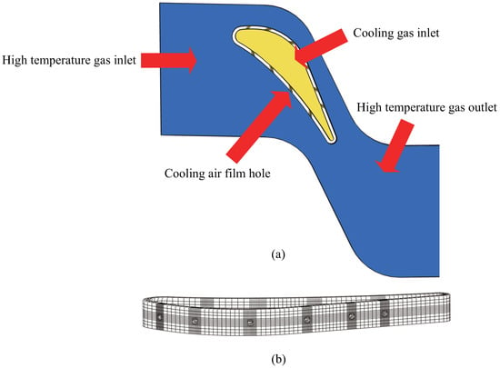
Figure 18.
(a) Geometrical model of turbine blade with multifilm cooling holes; (b) 3D mesh model of turbine blade with multifilm cooling holes.
The uneven temperature field of the multifilm cooling hole wall is shown in Figure 19. As can be seen from Figure 19, because the blade adopts the cooling method of a porous film, the temperature of most wall areas in the jet direction of the cooling hole is generally reduced, and a better thermal protection effect is obtained. However, there is a continuous local high-temperature region in the leading edge and upper- and lower-edge regions of the wall facing the incoming flow, which is due to the fact that there are no more cooling holes in this region, so that it is difficult to organize an effective cooling.

Figure 19.
Uneven temperature field of turbine blade with multifilm cooling holes.
Two cases were considered: (i) Case 1: turbine blades with uniform temperature; (ii) Case 2: turbine blade with uneven temperature. For point C (1 cm, 5.01 cm and 3.24 cm) at the base interface near the cooling hole, the distributions of displacement, temperature vs. time are shown in Figure 20. It can be found that compared with a uniform temperature, the turbine blade at a nonuniform temperature is affected by air-film cooling, resulting in inconsistent temperature values in each part of the blade wall surface. The convergence rate of displacement and temperature with time is affected, and the amplitude of each physical quantity decreases to a certain extent. The corresponding nephograms at 500 s and 2000 s are presented in Figure 21.
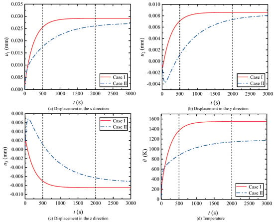
Figure 20.
Displacement, temperature for TBCs structure with uneven temperature field.
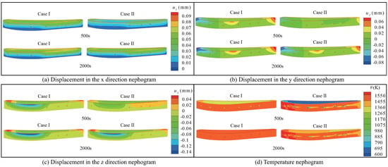
Figure 21.
Nephograms of thermo–mechanical responses in Case 1 and Case 2.
8. Conclusions and Future Work
The dynamic coupling analysis method proposed in this study is of significant meaning both in theory and practice and has the prospect of further expansion. The highlights of this research work are as follows:
From the theoretical point, this study carried out the dynamic coupling analysis on the thermo–chemo–mechanical field and fluid–structure interaction for an aero-engine turbine with functional gradient TBCs and presented a 3D computational framework. The thermo–mechanic–chemical governing equations of the substrate and TBCs were formulated by using the SE method and the XLW method, respectively. The final governing equation of the overall blade structure was assembled by defining the compatibility conditions of displacement, temperature, concentration and internal force equilibrium at the TBCs/substrate interface. The time integration was performed to calculate the TCM responses. The fluid–thermal coupling analysis was conducted to solve the flow field of the turbine blade with a cooling structure, and the obtained nonuniform thermal load was also input into the XLW/SE method. In the numerical examples, a computing program was adopted to calculate the dynamic responses of a turbine blade with and without debonding and delamination damages. By comparing the results of the XLW/SE model and a 3D elastic model developed by COMSOL, the effectiveness of the proposed XLW/SE method was validated.
From a practical point of view, the XLW/SE method enabled us to solve the coupling effects of the complex curved surface structure with TBCs and analyze the impacts of damage and a nonuniform temperature field on the deformation displacement, concentration diffusion and temperature conduction. In addition, this study applied the proposed method to a real-world engine turbine blade, so as to obtain the dynamic coupling solution of the temperature field, concentration field, flow field and deformation field. Furthermore, for the subsequent damage prediction problem, the damage location and size could be further judged by the change of temperature and concentration, which had a certain practical application value.
The research work in this article is a foundational work, which needs further improvements to ensure the normal operation of turbine engines under harsher environmental conditions, for instance, the introduction of Eu3+ into yttria-stabilized-zirconia (YSZ) TBCs to improve the thermal insulation performance and interfacial fracture toughness of the coatings. In future work, the mechanical properties of this new material will be analyzed by a numerical calculation method (i.e., XLW/SE method), and verified through experiments.
In addition, this study mainly focused on temperature conduction, ion diffusion and deformation displacement. On the basis of existing research, the interface oxidation problem and calcium-magnesium-aluminum-silicate (CMAS) corrosion problem of thermal barrier coatings with complex curved surface structure can be studied, which can provide a guarantee for further revealing the failure mechanism of TBCs. Furthermore, the analysis results can provide guidance for improving the structural design of turbine blades.
Author Contributions
The work described here is part of D.L., H.Y., S.M. and J.Y.’s thesis. Conceptualization, D.L.; writing—original draft preparation, H.Y. and S.M.; writing—review and editing, D.L. and J.Y. All authors have read and agreed to the published version of the manuscript.
Funding
This research is supported by Natural Science Foundations of China (U1933102, 12072364).
Institutional Review Board Statement
Not applicable.
Informed Consent Statement
Not applicable.
Data Availability Statement
The datasets generated during and/or analyzed during the current study are available from the corresponding author on reasonable request.
Conflicts of Interest
The authors declare no conflict of interest.
Appendix A
The submatrices in the stiffness, damping and mass matrices of the mechanical field are expressed as
The submatrices in the stiffness matrices of the thermo–mechanical and chemo–mechanical fields are given by
The submatrices in the stiffness matrix of the thermal field are expressed as
The submatrices in the stiffness matrix of the chemical field are expressed as
The submatrices in the damping matrices of the thermo–mechanical fields are given by
The submatrices in the damping matrices of the mechanical–chemo fields are given by
where , , , is the stiffness coefficient. , and , are the temperature–stress coefficients and concentration–stress coefficients, respectively. and are the heat conduction coefficients and diffusion coefficients, respectively. is the density component coefficient.
References
- Zhang, D.; Cheng, Y.; Jiang, R. Turbine Blade Investment Casting Die Technology; Springer: Berlin/Heidelberg, Germany, 2018. [Google Scholar] [CrossRef]
- Yu, Z.Q.; Liu, J.; Li, C.; An, B. Experimental investigation of film cooling performance on blade endwall with diffusion slot holes and stator-rotor purge flow. J. Turbomach. 2021, 84171, V07BT12A015. [Google Scholar] [CrossRef]
- Li, H.-W.; Zhang, D.-W. Han Feng: Experimental investigation on the effect of hole diameter on the leading edge region film cooling of a twist turbine blade under rotation conditions. Appl. Therm. Eng. 2021, 184, 116386. [Google Scholar] [CrossRef]
- Pu, J.; Wang, F.Q.; Wang, J. Numerical investigation of effects of blockage, inclination angle, and hole-size on film cooling effectiveness at concave surface. J. Turbomach. 2021, 143, 1–59. [Google Scholar] [CrossRef]
- Zhu, R.; Zhang, G.; Li, S.; Xie, G. Combined-hole film cooling designs based on the construction of anti-kidney vortex structure. A review. J. Heat Transf. 2020, 143, 030801. [Google Scholar] [CrossRef]
- Jiang, J.; Jiang, L.; Cai, Z. Numerical stress analysis of the TBC-film cooling system under operating conditions considering the effects of thermal gradient and tgo growth. Surf. Coatings Technol. 2019, 357, 433–444. [Google Scholar] [CrossRef]
- Yugeswaran, S.; Amarnath, P.; Ananthapadmanabhan, P.V. Thermal conductivity and oxidation behavior of porous inconel 625 coating interface prepared by dual-injection plasma spraying. Surf. Coatings Technol. 2021, 411, 126990. [Google Scholar] [CrossRef]
- Elumalai, P.V.; Parthasarathy, M. Effect of Cerium Oxide Nanoparticles to Improve the Combustion Characteristics of Palm Oil Nano Water Emulsion using Low Heat Rejection Engine. Int. J. Green Energy 2021, 18, 1482–1496. [Google Scholar] [CrossRef]
- Elumalai, P.V.; Annamalai, K.; Dhinesh, B. Effects of thermal barrier coating on the performance, combustion and emission of DI diesel engine powered by biofuel oil–water emulsion. J. Therm. Anal. Calorim. 2019, 137, 593–605. [Google Scholar] [CrossRef]
- Xu, H.; Guo, H. Thermal Barrier Coatings; Woodhead Publishing Limited: Sawston, UK, 2011. [Google Scholar]
- Liu, J.H.; Liu, Y.B.; Liu, L.; He, X. Numerical simulation of thermal stress of thermal barrier coating on gas film cooled turbine guide vane. China Surf. Eng. 2018, 31, 11. [Google Scholar]
- Wang, L.P.; Zhang, J.Z.; Yao, Y. Numerical study on temperature distribution of air-cooled blades with thermal barrier coating. J. Aerosp. Power 2012, 27, 8. [Google Scholar]
- Zhou, Y.C.; Hashida, T. Coupled effects of temperature gradient and oxidation on thermal stress in thermal barrier coating system. Int. J. Solids Struct. 2001, 38, 4235–4264. [Google Scholar] [CrossRef]
- Zhang, W.; Zhang, J.; Wang, H.; Lou, W.; Liu, X. Influences of cr and co on the growth of thermally grown oxide in thermal barrier coating during high-temperature exposure. Coatings 2018, 8, 195. [Google Scholar] [CrossRef]
- Tawancy, H.M.; Mohammad, A.I.; Al-Hadhrami, L.M. On the performance and failure mechanism of thermal barrier coating systems used in gas turbine blade applications: Influence of bond coat/superalloy combination. Eng. Fail. Anal. 2015, 57, 1–20. [Google Scholar] [CrossRef]
- Chen, P.-W.; Wang, S.-M.; Wang, F.-H. Fracture analysis of thermal barrier coating delamination under thermal shock. Procedia Eng. 2015, 99, 344–348. [Google Scholar] [CrossRef]
- Bhatnagar, H.; Ghosh, S.; Walter, M.E. Parametric studies of failure mechanisms in elastic eb-pvd thermal barrier coatings using fem. Int. J. Solids Struct. 2006, 43, 4384–4406. [Google Scholar] [CrossRef]
- Yildirim, B.; Erdogan, F. Edge crack problems in homogenous and functionally graded material thermal barrier coatings under uniform thermal loading. J. Therm. Stress. 2004, 27, 311–329. [Google Scholar] [CrossRef]
- Ueda, S.; Nakano, Y. An axisymmetric crack in a functionally graded thermal barrier coating bonded to a homogeneous elastic substrate under transient thermal loading. J. Therm. Stress. 2018, 43, 940–961. [Google Scholar] [CrossRef]
- Ueda, S.; Nakano, Y. A normal crack in a functionally graded thermal barrier coating bonded to a homogeneous elastic substrate under transient thermal loading. J. Therm. Stress. 2018, 41, 1487–1500. [Google Scholar] [CrossRef]
- Xiao, Y.Q.; Yang, L.; Zhu, W.; Zhou, Y.C. Delamination mechanism of thermal barrier coatings induced by thermal cycling and growth stresses. Eng. Fail. Anal. 2021, 121, 105202. [Google Scholar] [CrossRef]
- Shan, W.K.; Li, D.H. Thermo-mechanic-chemical coupling fracture analysis for thermal barrier coating based on extended layerwise method. Surf. Coat. Technol. 2021, 405, 126520. [Google Scholar] [CrossRef]
- Li, D.H. Layerwise theories of laminated composite structures and their applications. A review. Arch. Comput. Methods Eng. 2021, 28, 577–600. [Google Scholar] [CrossRef]
- Li, D.H.; Zhang, F. Full extended layerwise method for the simulation of laminated composite plates and shells. Comput. Struct. 2017, 187, 101–113. [Google Scholar] [CrossRef]
- Li, D.H. Extended layerwise method of laminated composite shells. Compos. Struct. 2016, 136, 313–344. [Google Scholar] [CrossRef]
- Li, D.H. Delamination and transverse crack growth prediction for laminated composite plates and shells. Comput. Struct. 2016, 177, 39–55. [Google Scholar] [CrossRef]
- Li, D.H.; Zhang, X.; Sze, K.Y.; Liu, Y. Extended layerwise method for laminated composite plates with multiple delaminations and transverse cracks. Comput. Mech. 2016, 58, 657–679. [Google Scholar] [CrossRef]
- Li, D.H.; Zhang, F.; Xu, J.X. Incompatible extended layerwise method for laminated composite shells. Int. J. Mech. Sci. 2016, 119, 243–252. [Google Scholar] [CrossRef]
- Li, D.H.; Liu, Y.; Zhang, X. An extended layerwise method for composite laminated beams with multiple delaminations and matrix cracks. Int. J. Numer. Methods Eng. 2015, 101, 407–434. [Google Scholar] [CrossRef]
- Lu, X.; Yang, J.Y.; Xu, D.; Wu, Y.G.; Li, D.H. Extended layerwise/solid-element method of composite sandwich plates with damage. Mech. Adv. Mater. Struct. 2019, 26, 1376–1389. [Google Scholar] [CrossRef]
- Lu, X.; Yang, J.Y.; Wu, Y.G.; Zhang, F.; Li, D.H. An extended layerwise/solid-element method of stiffened composite plates with delaminations and transverse crack. Int. J. Mech. Mater. Des. 2018, 14, 345–358. [Google Scholar] [CrossRef]
- Li, D.H.; Wang, R.P.; Qian, R.L.; Liu, Y.; Qing, G. Static response and free vibration analysis of the composite sandwich structures with multi-layer cores. Int. J. Mech. Sci. 2016, 111–112, 101–115. [Google Scholar] [CrossRef]
- Li, D.H.; Liu, Y.; Zhang, X. A layerwise/solid-element method of the linear static and free vibration analysis for the composite sandwich plates. Compos. Part B Eng. 2013, 52, 187–198. [Google Scholar] [CrossRef]
- Li, D.H.; Liu, Y.; Zhang, X. Linear statics and free vibration sensitivity analysis of the composite sandwich plates based on a layerwise/solid-element method. Compos. Struct. 2013, 106, 175–200. [Google Scholar] [CrossRef]
- Li, D.H.; Liu, Y.; Zhang, X. Low-velocity impact responses of the stiffened composite laminated plates based on the progressive failure model and the layerwise/solid-elements method. Compos. Struct. 2014, 110, 249–275. [Google Scholar] [CrossRef]
- Li, D.H.; Qing, G.H.; Liu, Y. A layerwise/solid-element method for the composite stiffened laminated cylindrical shell structures. Compos. Struct. 2013, 98, 215–227. [Google Scholar] [CrossRef]
- Li, D.H.; Liu, Y. Three-dimensional semi-analytical model for the static response and sensitivity analysis of the composite stiffened laminated plate with interfacial imperfections. Compos. Struct. 2012, 94, 1943–1958. [Google Scholar] [CrossRef]
- Li, D.H.; Fish, J. Thermomechanical extended layerwise method for laminated composite plates with multiple delaminations and transverse cracks. Compos. Struct. 2017, 185, 665–683. [Google Scholar] [CrossRef]
- Li, D.H.; Shan, W.K.; Zhang, F. Steady-state thermomechanical analysis of composite laminated plate with damage based on extended layerwise method. Arch. Appl. Mech. 2020, 90, 415–435. [Google Scholar] [CrossRef]
- Li, D.H.; Shan, W.K. Numerical fracture analysis for chemo-mechanical coupling problems in multilayered porous media. Int. J. Mech. Sci. 2019, 172, 105412. [Google Scholar] [CrossRef]
- Hass, D. Thermal Barrier Coatings via Directed Vapor Deposition; University of Virginia: Charlottesville, VA, USA, 2001; Volume 62, p. 470. [Google Scholar]
Publisher’s Note: MDPI stays neutral with regard to jurisdictional claims in published maps and institutional affiliations. |
© 2022 by the authors. Licensee MDPI, Basel, Switzerland. This article is an open access article distributed under the terms and conditions of the Creative Commons Attribution (CC BY) license (https://creativecommons.org/licenses/by/4.0/).