Article

Hydrostatic Bearing Characteristics Investigation of a Spherical Piston Pair with an Annular Orifice Damper in Spherical Pump

1
College of Mechanical Engineering, Yangzhou University, Yangzhou 225127, China
2
Changchai Company Limited, Changzhou 213002, China
*
Author to whom correspondence should be addressed.
Coatings 2021, 11(8), 1007; https://doi.org/10.3390/coatings11081007
Submission received: 15 July 2021 / Revised: 9 August 2021 / Accepted: 20 August 2021 / Published: 23 August 2021

Abstract

:
The spherical pump is a totally new hydraulic concept, with spherical piston and hydrostatic bearing, in order to eliminate the direct contact between the piston and cylinder cover. In this paper, the governing Reynolds equation under spherical coordinates has been solved and the hydrostatic bearing characteristics are systematically investigated. The operating sensitivities of the proposed spherical hydrostatic bearing, with respect to the piston radius, film beginning angle, film ending angle, film thickness, and temperature, are studied. The load carrying capacity, pressure drop coefficient, stiffness variation of the lubricating films, leakage properties, and leakage flow rates are comprehensively discussed. The related findings provide a fundamental basis for designing the high-efficient spherical pump under multiple operating conditions. Besides, these related results and mechanisms can also be utilized to design and improve other kinds of annular orifice damper spherical hydraulic bearing systems.

1. Introduction

The hydrostatic bearing consists of a fluid layer between two surfaces, whose purpose is to avoid direct surface-to-surface contact [1,2,3,4,5,6]. Generally, hydrostatic bearings are utilized in heavy equipment, to carry large loads between two surfaces that are moving relative to each other at a low speed [4].
The spherical pump is a totally new hydraulic concept and consists of a pump with a spherical piston. As demonstrated in the previous work [7,8,9,10,11,12,13,14], the rotation speed of the spherical piston is only half the rotational speed of its shaft. It is, therefore, characterized by its relatively low rotation speed. Additionally, the spherical piston has a large load carrying capacity, because of the pump’s spatial structure and special working mechanism. Hence, it is proper to utilize a hydrostatic bearing to support the spherical piston and to mitigate direct contact between the spherical piston and cylinder block.
Extensive studies have been conducted to investigate hydrostatic bearing performance [4,5,15]. The operating sensitivity of hydrostatic bearings, with respect to pressure-induced deformation, were studied by Manring [4]. The latter have described the pressure distributions, flow rates, and load carrying capacities of the bearings, by using lubrication equations for low Reynolds’ number flow. Expressions were developed to consider deformations of both concave and convex shapes, and the impact of both shapes were compared. However, the bearing they studied is a flat thrust bearing, rather than a spherical bearing. In another paper, Nie [5] has proposed a hydrostatic slipper bearing, with an annular orifice damper in a water hydraulic axial piston motor, and the reaction forces, including friction forces, centrifugal forces, and the piston dynamics, are considered. They established a characteristic equation for hydrostatic slipper bearings and the influences of different structural parameters, such as clearance, supporting length, and damping length, are included in their studies. However, they did not consider the leakage and flow rate properties of the hydrostatic bearing. Pang et al. [15] studied the hydrostatic lubrication of the slipper, in a high-pressure plunger pump, by considering the pressure-viscosity effects of the lubricating surface. These authors also investigated the dynamic stiffness properties of the oil film. However, they did not cover the effect of temperature on hydrostatic bearing performance. In addition, the slipper is also supported by a flat hydrostatic bearing. Yamaguchi [16,17,18,19,20,21] conducted abundant research on hydrostatic bearings. They established a mixed lubrication model [16,17,19], which consists of the Greenwood–Williamson model [22] for non-lubricated rough surfaces in contact, as well as the Patir and Cheng mean flow model [23,24]. The effects of surface roughness, eccentric, loading pressure and rotation speed on the bearing’s friction, as well as flow rate and power losses, were studied theoretically in [16,17]. A test rig was established to investigate the mixed lubrication characteristics of hydrostatic bearings [19]. The experimental results show good agreement with the proposed theoretical model. The properties of disk-type hydrostatic thrust bearings supporting concentric loads, simulating the major bearing/seal parts of water hydraulic motors and pumps, are studied in [20]. Both theoretical and experimental approaches are utilized, to investigate the relationships between film thickness, flow rate leakage, working pressure, and load carrying capacity. Later, a theoretical model was used to investigate bearings that are loaded eccentrically. The power loss properties, stiffness, and load carrying capacities of the disk-type hydrostatic thrust bearings are analyzed theoretically in [21]. Another related research was conducted by Hooke et al. [25,26,27,28]. However, all their studies cover disk-type hydrostatic thrust bearings, rather than spherical bearings.
Static and dynamic analyses on spherical bearings were investigated by Goeka and Booker, using finite element methods [29]. Xu and Jiang [30,31] have proposed a self-compensation hydrostatic spherical hinge, which can provide a large load carrying capacity. The effects of centripetal force and surface roughness on the bearing performance of spherical fitted bearings were studied by Yacout [32]. However, all these publications are generally focused on traditional hydrostatic bearings. It should be noted that the structure and working mechanism are different for the hydrostatic bearings that are utilized in spherical pumps.
In this study, the operating sensitivity of the proposed spherical hydrostatic bearing, with respect to the piston radius R, film beginning angle θ1, film ending angle θ2, film thickness h, and temperature t, are also studied. By using the continuity equation of incompressible, lubricating fluid, related expressions are derived for describing the load carrying capacity, pressure drop coefficient, stiffness variation of the lubricating film, leakage properties, the effect of temperature on leakage, and the flow rate of the leakage.

2. Hydrostatic Bearing Model for Spherical Cylinder–Piston Pair

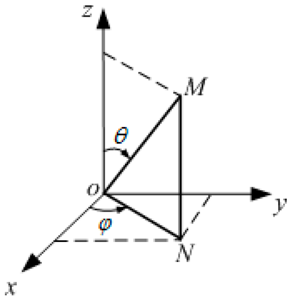
2.1. Theoretical Analysis

As shown in Figure 1, any point can be expressed as M(x, y, z) in Cartesian coordinates as follows:
{ x M = r sin θ c o s φ y M = r sin θ sin φ z M = r cos θ
and also in the spherical coordinates (r, θ, φ). The latter are related to Cartesian coordinates (x, y, z) by the following:
{ r = x 2 + y 2 + z 2 θ = arccos z x 2 + y 2 + z 2 φ = arctan y x
where r represents the distance (radius) from a point M to the origin O, θ indicates the polar angle from the positive z-axis, with 0 ≤ θ ≤ π, and φ is the azimuthal angle in the xy plane from the x-axis, with 0 ≤ φ ≤ 2π.
Therefore, we can express the Navier-Stokes equations for the incompressible lubricating fluid with uniform viscosity in a spherical coordinates system, (r, θ, φ), as follows:
{ ρ [ D u r D t u θ 2 + u φ 2 r ] = p r + f r + μ [ 2 u r 2 u r r 2 2 r 2 u θ θ 2 u θ cot θ r 2 2 r 2 sin θ u φ φ ] ( 3 a ) ρ [ D u θ D t + u θ u r r u φ 2 cot θ r ] = 1 r p θ + f θ + μ [ 2 u θ + 2 r 2 u r θ u θ r 2 sin 2 θ 2 cot θ r 2 sin θ u φ φ ] ( 3 b ) ρ [ D u φ D t + u φ u r r + u θ u φ cot θ r ] = 1 r sin θ p φ + f φ + μ [ 2 u φ + 2 r 2 sin θ u r φ u φ r 2 sin 2 θ + 2 cot θ r 2 sin θ u θ φ ] ( 3 c )
where ρ and p represent the density and pressure of the lubricating fluid, ur, uθ and uφ are the velocities in the three coordinate directions, and μ indicates the dynamic viscosity. The body force components are denoted by fr, fθ and fφ, and the Laplacian operator is as follows:
2 = 1 r 2 r ( r 2 r ) + 1 r 2 sin θ θ ( s i n θ θ ) + 1 r 2 sin 2 θ 2 2 φ
and the operator D/Dt is denoted by the following:
D D t = t + u r r + u θ r θ + u φ r sin θ φ

2.2. Modeling of the Piston–Cylinder Hydrostatic Bearing

In this section, the model of the piston–cylinder bearing pair is established based on the theory mentioned in Section 2.1.
Figure 2 depicts the piston and cylinder, with the dashed line representing the inner surface of the cylinder body. The lubricating system consists of high-pressure lubricating fluid, Pr, being injected into the piston’s top gap, at which time the bearing film is established on the piston’s surface and cylinder body, which is an annulus structure. This annulus structure is also defined as the revolute joint, which is the joint of the piston and cylinder body (Video S1). Therefore, in spherical coordinates, (r, θ, φ), the continuity equation of the lubricating fluid is as follows [33]:
1 r 2 r ( r 2 u r ) + 1 r sin θ θ ( u θ sin θ ) + 1 r sin θ u φ φ = 0
As the fluid flows uniformly from the piston pin, it can be concluded that the velocity uφ is 0, which is perpendicular to the inlet direction. Furthermore, because the lubricating film thickness is at the micrometer scale, we can assume that the flow in the r direction also vanishes and ur = 0. Therefore, Equation (7) can be transformed to the following:
u θ θ = cot θ u θ
Supposing the lubricating fluid is steadily flowing, the acceleration of the three different directions are u r t = 0 , u θ θ = 0 and u φ φ = 0 , respectively. The eliminating lubricating fluid inertia yields u θ 2 + u φ 2 r = 0 . Additionally, φ = 0 and uφ = 0, since the piston is symmetrical along the φ direction. Therefore, Equation (3) simplifies to the following:
{ p r + μ ( 2 r 2 u θ θ + 2 u θ cot θ r 2 ) = 0 ( 8 a ) ρ u θ r u θ θ = 1 r p θ + μ [ 2 r u θ r + 2 u θ r 2 + cot θ r 2 u θ θ + 1 r 2 2 u θ θ 2 u θ r 2 sin 2 θ ] ( 8 b ) p φ = 0 ( 8 c )
Substituting Equation (7) into Equation (8a), we arrive at the following:
p r = 0
indicating that the lubricating oil pressure, p, only varies with θ. Therefore, the pressure distribution along the θ direction can be obtained based on the flow theory between the parallel surfaces and Equation (8b).
d p d θ = μ r ( 2 r u θ r + 2 u θ r 2 )
The velocity uθ can be obtained by integrating r into the following:
u θ = r 2 μ d p d θ a r + b
where a and b are two different integral constants. Substituting the boundary conditions as follows:
u θ | r = R = 0
and the following:
u θ | r = R + h = 0
into Equation (11), the velocity distribution at different θ can be expressed as follows:
u θ = [ r 2 r ( 2 R + h ) + R ( R + h ) ] 2 μ r d p d θ
where h is the clearance between the piston surface and the internal surface of the cylinder body. Consequently, the lubricating fluid flow can be obtained from the following:
Q = R R + h 2 π r sin θ u θ d r = π h 3 sin θ 6 μ d p d θ
Substituting h = ecosθ into Equation (15), and evaluating the integral by using the separation of the variables approach, yields the following:
p s p d p = θ 1 θ 6 μ Q π e 3 cos 3 θ sin θ d θ
where the eccentricity e indicates the distance between the piston center and the center of the cylinder body. The symbol ps denotes the inlet lubricating fluid pressure of the spherical piston, and θ1 represents the initial angle of the lubricating film. Therefore, the pressure distribution of the lubricating fluid can be expressed as follows:
p = p s 3 μ Q π e 3 [ 2 ln tan θ tan θ 1 + tan 2 θ tan 2 θ 1 ]
As shown in Figure 2, the fluid pressure p = 0 when θ = θ2, where θ2 is the lubricating film ending angle. By substituting this boundary condition into Equation (17), the leaking lubricating fluid at the piston surface can be obtained as follows:
Q = p s π e 3 3 μ [ 2 ln tan θ 2 tan θ 1 + tan 2 θ 2 tan 2 θ 1 ]
The substitution of Equation (18) into Equation (17) yields a pressure distribution as follows:
p = p s [ 1 2 ln tan θ tan θ 1 + tan 2 θ tan 2 θ 1 2 ln tan θ 2 tan θ 1 + tan 2 θ 2 tan 2 θ 1 ]
When eliminating the bearing force between the clearance of d2d1, the bearing force of the spherical piston can be obtained as follows:
F = θ 1 θ 2 ( 2 π R sin θ ) × ( p cos θ ) × R d θ = π R 2 p s [ cos 2 θ 1 ( tan 2 θ 2 tan 2 θ 1 ) 2 sin 2 θ 1 ln tan θ 2 tan θ 1 ] 2 ln tan θ 2 tan θ 1 + tan 2 θ 2 tan 2 θ 1
and Equation (20) can be simplified as follows:
F = p s S e
where S e = π R 2 [ cos 2 θ 1 ( tan 2 θ 2 tan 2 θ 1 ) 2 sin 2 θ 1 ln tan θ 2 tan θ 1 ] 2 ln tan θ 2 tan θ 1 + tan 2 θ 2 tan 2 θ 1 represents the spherical piston effective bearing area. We can observe that it only varies with the lubricating angles θ1 and θ2. Generally, the initial angle of the lubricating film, θ1, is related to the piston pin diameter, d1. The bigger the piston pin, the larger the beginning angle, which can be expressed as follows:
θ 1 = arcsin d 1 2 R
The final angle of the lubricating film, θ2, is predominantly related to the pump working capability, i.e., the pump displacement.

3. Bearing Properties Analysis

In this section, the properties of the hydrostatic pair, under different structural parameters, will be analyzed, based on the above established theory.
Firstly, the effective bearing area, Se is affected by both the angles θ1 and θ2, and the piston bearing capacity is subsequently dependent on Se. The initial angle θ1 is specified by the piston pin diameter d1. Therefore, both d1 and θ2 may impact the hydrostatic bearing working capacity directly. Generally, θ2 is less than 90°, due to the fact that the lubricating film thickness, h, is equal to ecosθ and h > 0.

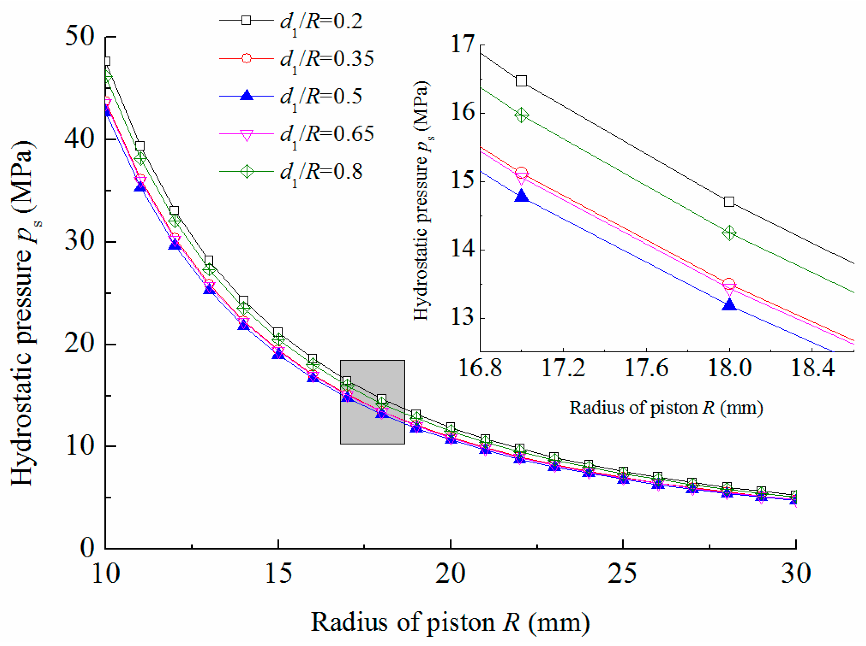
3.1. Variation in Hydrostatic Pressure

The effects of the piston radius and the piston pin diameter on the bearing pressure are studied in this section.
The variation tendency of the hydrostatic pressure with the piston radius are sketched in Figure 3. The bearing force is 5000 N and the lubricating film final angle θ2 is set to 60°, as this is the most utilized angle for spherical pistons.
From Figure 3, we can observe that when the angle θ2 and the bearing force are constants, the hydrostatic pressure of the bearing pair, ps, decreases with the piston radius. The larger the piston radius, the smaller the needed hydrostatic pressure is. This is due to the fact that the bearing area increases with the piston radius. However, the hydrostatic pressure changes significantly differently, with d1/R reaching a minimum value when d1/R is equal to 0.5.
To study this phenomenon further, Figure 4 is presented. The plot horizontal axis is the ratio between the piston pin diameter and the piston radius. The final angle ranges from 60° to 80°, with an interval of 5°. Generally, a larger angle θ2 requires a lower hydrostatic pressure when the bearing force is fixed. The lowest hydrostatic pressure occurs when θ2 is 80°, while the highest hydrostatic pressure occurs when θ2 is 60°, as demonstrated in Figure 4. However, for a specific angle θ2, multiple variation tendencies appeared. When the angle is 80°, the hydrostatic pressure increases almost linearly with d1/R. In other words, if we do not consider the effect of structural strength, a smaller d1/R is desired for the best piston lubricating conditions. As the angle θ2 gradually decreases, this circumstance changes. When θ2 is 75°, 70°, 65°, and 60°, the lowest hydrostatic pressure occurs when d1/R is 0.38, 0.44, 0.48, and 0.5, respectively. A minimum hydrostatic pressure occurs when d1/R is between 0.2 and 1. Furthermore, the smallest hydrostatic pressure occurs at a higher d1/R ratio, when the angle θ2 decreases from 80° to 60°.
Therefore, the optimum d1/R ratio that corresponds to the lowest hydrostatic pressure can be found in Figure 2, for each specific angle θ2. This is particularly helpful to know when designing new spherical pumps.

3.2. Variation in Bearing Force

The bearing force change with the ending angles is illustrated in Figure 5. The piston radius is 20 mm, with a hydrostatic pressure of the lubricating film of 15 MPa.
From Figure 5, we can observe that the bearing force increases at different growth rates with the piston final angle. Take d1/R = 0.6 as an example, its bearing force grows almost linearly when the final angle is between 60° and 85°. However, the growth rate decreases when θ2 is higher than 85°. Furthermore, the d1/R ratio will also affect the piston bearing force. A smaller ratio, d1/R, leads to a higher increment of the bearing force, when θ2 varies from 60° to 90°. This leads to the conclusion that the smaller the d1/R is, the higher the bearing force is, under the same conditions.

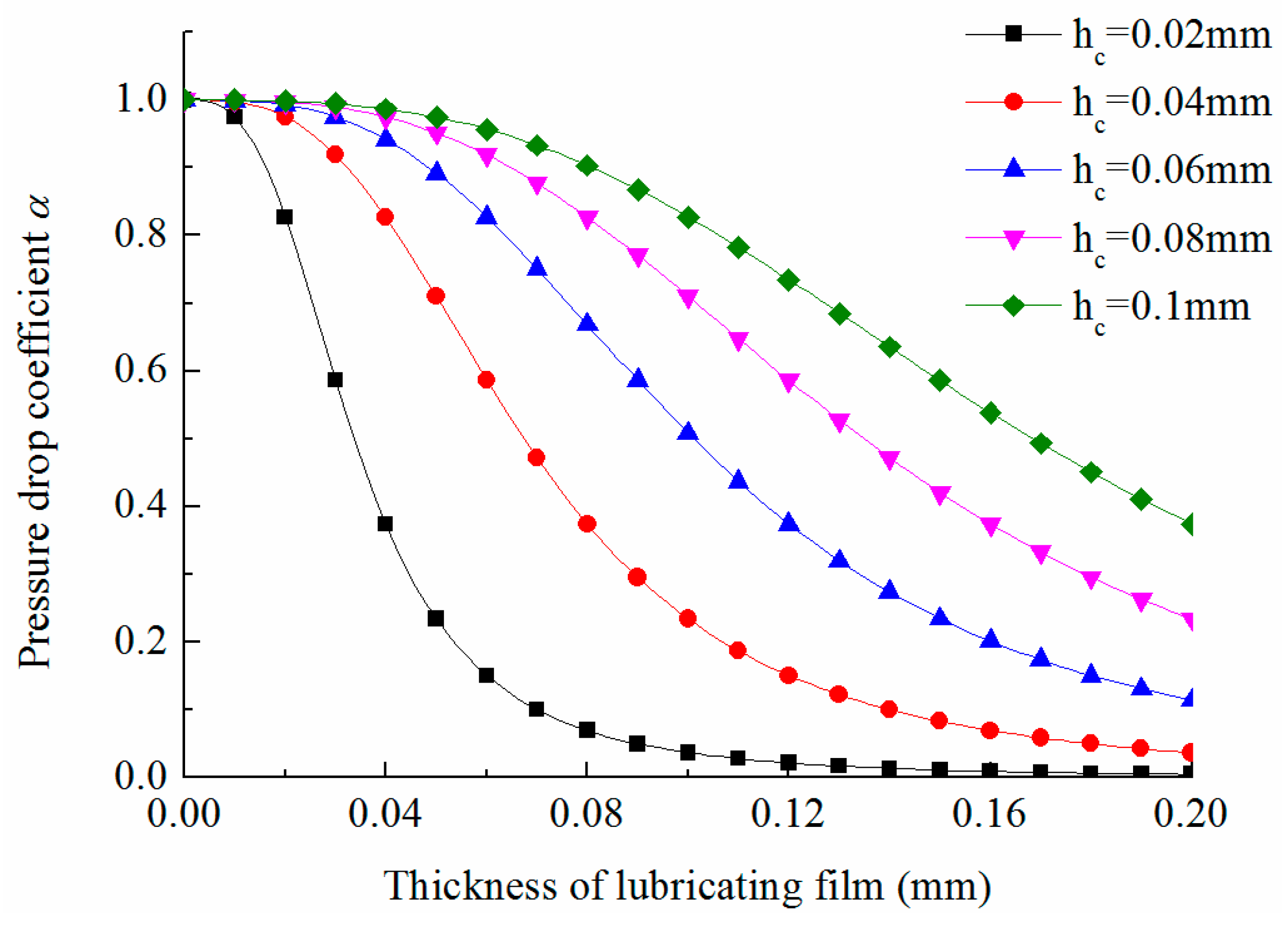
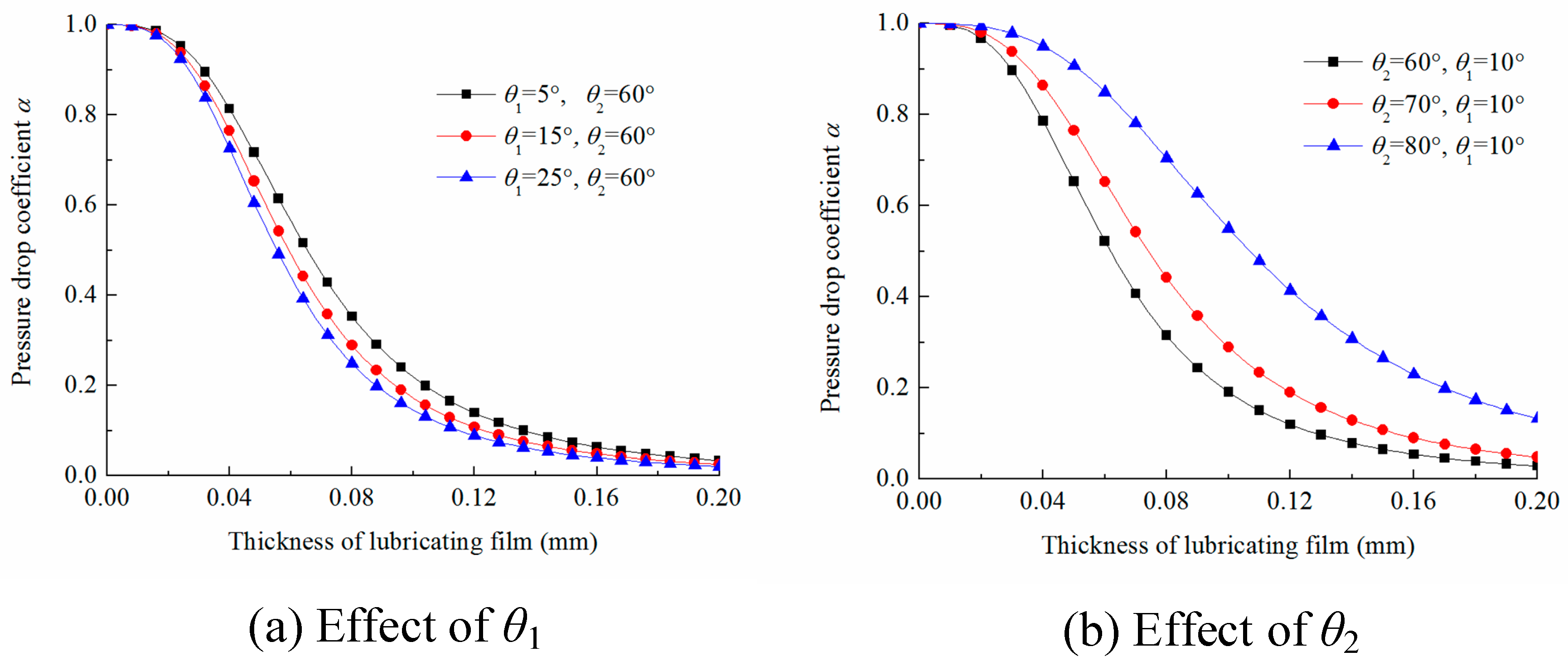
3.3. Variation in Pressure Drop Coefficient

An equivalent fluid bridge of the hydrostatic bearing system is illustrated in Figure 6. Lubricating oils are injected from the clearance between the piston pin and the cylinder cover. The fluid resistance of the clearance is denoted by Rc, which is a constant, and Rg represents the adjustable fluid resistance of the hydrostatic bearing pair.
Based on the continuity theorem, we obtain the following:
p s R g = p c R c
where pc = prps represents the pressure drops at the clearance of the piston pin and the cylinder cover. The pressure drop of the lubricating pair is indicated by ps. Therefore, the pressure drop ratio of the piston and the whole system can be expressed as follows:
α = p s p r = R s R c + R s
This is also called the pressure drop coefficient. Rc is the fluid resistance between the clearance of the piston pin and the cylinder cover. It is expressed as follows:
R c = 12 μ l π d 1 h c 3 = 96 μ l π d 1 ( d 2 d 1 ) 3
where d1 and d2 are the diameters of the piston pin and its mating hole, respectively. The axial length of the revolute joint is l, and the clearance between the piston pin and the matching hole of the cylinder cover is denoted by (d2d1)/2. The fluid resistance between the spherical surface of the piston and cylinder cover is denoted by Rs, which is expressed as follows:
R s = 3 μ [ tan 2 θ 2 tan 2 θ 1 + 2 ln tan θ 2 tan θ 1 ] π h 3
Substituting Equations (25) and (26) into Equation (24), we obtain the following:
α = R s R c + R s = 1 1 + 12 μ l π d 1 h c 3 × π h 3 3 μ [ tan 2 θ 2 tan 2 θ 1 + 2 ln tan θ 2 tan θ 1 ]
If we set K B C = 12 l d 1 h c 3 and K B S = 1 3 [ tan 2 θ 2 tan 2 θ 1 + 2 ln tan θ 2 tan θ 1 ] , then Equation (27) can be expressed as follows:
α = 1 1 + K B C K B S h 3
The KBC and KBS are structural parameters of the revolute joint and bearing pair, and both relate to their own structure and geometry properties. Equation (28) is also called a characteristic equation, which reflects the bearing characteristics of the entire hydrostatic bearing system.
The effects of KBC and KBS on the bearing characteristics are illustrated in Figure 7 and Figure 8. The piston pin, diameter d1, is 5 mm and its length, l, is 5 mm as well.
In Figure 7, the clearance of the revolute joint, hc, varies from 0.02 mm to 0.1 mm, with an interval of 0.02 mm. The structural angles θ1 and θ2 are 15° and 75°, respectively. From Figure 7, we can observe that the pressure drop decreases with various speeds, when the lubricating film thickness increases. When the lubricating film thickness is smaller than 0.02 mm, or thicker than 0.12 mm, its variation has little impact on the pressure drop coefficient. When hc is equal to 0.02 mm, the pressure drop coefficient is more sensitive to the lubricating film thickness, especially when the thickness varies from 0.02 mm to 0.08 mm. This means that the bearing film stiffness is higher in this range. When hc increases from 0.02 to 0.1, the pressure drop graph becomes more and more flat, and the sensitivity of the pressure drop coefficient on the lubricating film thickness decreases gradually. This means that the lubricating film stiffness decreases as hc increases. Obviously, a higher bearing stiffness can be obtained when using a smaller clearance hc, but the lubricating film thickness must locate within an appropriate range.
The effects of KBS on the bearing characteristics are demonstrated in Figure 8. The effects of θ1 and θ2 are illustrated in Figure 8a,b, respectively. We can observe that, similarly to Figure 7, when the lubricating film thickness is smaller than 0.02 or thicker than 0.12, the pressure drop coefficient decrease very slowly.
In Figure 8a, θ2 is 60° and θ1 has 5°, 15° and 25° values. When θ1 increases from 5° to 25°, the pressure drop coefficient cure moves left, meaning that α becomes more sensitive to h and higher lubricating film stiffness values are realizable. In Figure 8b, θ1 is equal to 10°, while θ2 increases from 60° to 80°. The pressure drop coefficient curve moves to the right when θ2 increases, which is totally different compared to θ1. Obviously, the lubricating film stiffness decreases with θ2. Furthermore, when comparing Figure 8a,b, we find that θ2 has a larger effect on the pressure drop coefficient than θ1.

3.4. Lubricating Film Stiffness Analysis

Lubricating film stiffness is defined as follows:
J = d F d h
where F denotes the bearing force, which is defined by Equation (21), and h indicates the lubricating film thickness. Therefore, the lubricating film stiffness represents the bearing force change rate with different film thicknesses. Substituting Equations (21), (24) and (28) into Equation (29), leads to the following:
J = 3 K B C K B S p r S e h 2 ( 1 + K B C K B S h 3 ) 2
From Equation (30), we can observe that the stiffness of the lubricating film is not only affected by the structural parameters KBC and KBS, but it is also affected by the hydrostatic pressure pr, effective bearing area Se and thickness of lubricating film h. The extremes of the film thickness, h, can be obtained when J / h = 0 and the maximum lubricating film thickness is as follows:
h max = ( 2 k B C k B S ) 1 3
Substituting Equation (31) into Equations (28) and (30), we can obtain the maximum pressure drop coefficient α = 2/3 and the maximum bearing stiffness as follows:
J max = 4 2 / 3 3 p r S e ( K B C K B S ) 2 3
Then, a dimensionless stiffness coefficient, δ, can be determined. The ratio between Equations (30) and (32) is as follows:
δ = J J max = 9 4 2 / 3 ( K B C K B S ) 2 / 3 h 2 ( 1 + K B C K B S h 3 ) 2
The effects of KBC and KBS on the dimensionless stiffness coefficients of the lubricating film are illustrated in Figure 9 and Figure 10. Both the diameter and the length of the piston pin are 5 mm.
From Figure 9 and Figure 10, we can observe that the dimensionless stiffness coefficient increases with the lubricating film thickness, h, firstly, and arrives at a maximum value of one. Then, it decreases from this maximum value, with different variation tendencies. Figure 9 demonstrates that a smaller piston pin clearance makes the maximum stiffness occur at a smaller film thickness. As demonstrated in Figure 10a, when the angle θ2 is a constant, a larger θ1 will make the stiffness curve move left. Conversely, when θ1 is a constant and θ2 is increased, the curves of the dimensionless stiffness coefficients will move to the right. This means that the maximum stiffness occurs when the lubricating film is thicker.
The structural parameters KBC and KBS will increase when increases θ1, decreases hc and θ2. Therefore, it can be concluded that when KBC and KBS increase, the maximum value of these curves will move to the left, which makes the film thickness of the maximum stiffness smaller, and, finally, impacts the hydrostatic bearing performance.

3.5. Leakage Analysis

A proper fit clearance should exist between spherical pistons and cylinder bodies. Consequently, leakage will inevitably exist through the clearance. In this section, the leakage properties of lubricating surfaces will be investigated and discussed.
The leakage characteristics of the lubricating surface are illustrated by Equation (19), which demonstrates that leakage is directly proportional to lubricating pressure ps, eccentricity e3, and inversely proportional to the dynamic viscosity coefficient μ. Furthermore, it is also related to the structural parameters θ1 and θ2.
The results shown in Figure 11 are used to investigate the effect of eccentricity e on leakage. Here, the dynamic viscosity is selected as 0.01 Pa·s, and θ1 and θ2 are 15° and 75°, respectively. Three different lubricating pressures are selected at 5 MPa, 10 MPa, and 15 MPa. From Figure 11, we can observe that leakage increases sharply with eccentricity e. Furthermore, the higher the lubricating pressure, the larger the leakage. When eccentricity is smaller than 0.08 mm, the changes in leakage are slight. When e exceeds 0.08, the leakage change rate grows rapidly. Therefore, a proper lubricating clearance is essential at different working conditions.
The effects of lubricating pressure on leakage performance are illustrated in Figure 12. The dynamic viscosity coefficient μ and eccentricity e are 0.01 Pa·s and 0.05 mm, respectively. From Figure 12, we can observe that the leakage increases linearly with lubricating pressure. However, the different structural parameters θ1 and θ2 will have multiple effects on their leakage characteristics.
The effects of θ1 are demonstrated in Figure 12a, where θ2 is 60° and θ1 is 5°, 15°, and 25°. When θ1 increases, from 5° to 25°, the corresponding leakage increases gradually. Obviously, a smaller θ1 is helpful to prevent leakage of the lubricating pair. The impacts of θ2 are illustrated in Figure 12b, when θ1 is 15°, while θ2 is 60°, 70° and 80°, respectively. Distinct from the θ1 dependence, the increase in θ2 will prohibit leakage effectively. Furthermore, the effects of θ2 on leakage are stronger than θ1.
Therefore, an effective way to prohibit leakage from lubricating pairs is to decrease θ1 and increase θ2, with a larger θ2 being more helpful than a smaller θ1.

3.6. Effect of Temperature on Leakage Properties

Lubricating medium temperatures will inevitably increase when the spherical pump is running. On the one hand, the friction of the lubricating pair generates part of the heat flow. Leakage of the lubricating medium will also cause temperature increases, and a rise in temperature will further decrease the lubricant viscosity.
The viscosity of the lubricating medium is its sensitivity to temperature. Both theoretical and experimental studies are conducted to investigate their relation [34,35]. In this study, the utilized viscosity–temperature equation is expressed as follows [36]:
μ = μ 0 e β ( t t 0 )
where μ0 represents the initial viscosity, β denotes the viscosity–temperature coefficient, and t0 is the initial temperature.
Substituting Equation (34) into Equation (18), we can obtain the relationship between temperature and leakage, as follows:
Q = p s π e 3 3 μ 0 e β ( t t 0 ) [ 2 ln tan θ 2 tan θ 1 + tan 2 θ 2 tan 2 θ 1 ]
The leakage characteristics under different temperatures are illustrated in Figure 13. The initial temperature t0 is 20 °C; viscosity-temperature coefficient β is 1/20 °C−1; the lubricating pressure ps is 15 MPa; and the eccentricity is 0.05 mm. The structural parameters θ1 and θ2 are 15° and 60°, respectively.
From Figure 13, we can observe that the leakage curves of the lubricating pair increase nonlinearly with temperature. Leakage increases sharply with temperature, when the temperatures are below 80 °C. At temperatures higher than 80 °C, both the leakages curves are at approximately 0.12 L/min. This is because the viscosity of the lubrication decreases to almost 0 Pa·s when the temperature is higher than 80 °C. The initial dynamic viscosity also has an impact on the leakage performance, namely, the higher the initial dynamic viscosity, the larger the amount of leakage.

3.7. Flow Rate Characteristics of Leakage Medium

Transparent leakage of the bearing film can be expressed as follows:
Q = V f r S f r = V f r 2 π R sin θ h
where Vfr is the flow rate of a specific surface, which is perpendicular to the piston axis, and the specific surface is constituted by the clearance between the piston and the cylinder cover. The area of the specific surface is denoted by Sfr, which is equal to 2πRsinθh.
Substituting Equation (18) and h = ecosθ into Equation (36), the flow rate of the surfaces with different θ angles can be obtained from the following:
V f r = e 2 p s 3 μ R sin 2 θ [ 2 ln tan θ 2 tan θ 1 + tan 2 θ 2 tan 2 θ 1 ]
The flow rates of the leakage media are displayed in Figure 14. The structural angles θ1 and θ2 are 15° and 75°, respectively, the piston radius is 20 mm, and the dynamic viscosity µ and eccentricity e are 0.01 Pa·s and 0.05 mm, respectively. The pressure drop, ps, is 8 MPa, 9 MPa, and 10 MPa. The effects of angle θ on the flow rate are similar to a quadratic curve. The lowest flow rate occurs when θ is 45°, and the highest flow rate takes place when θ is 15° and 75° for this specific structure. The flow rate decreases when θ < 45°, while it increases when 45° < θ < 75°.

4. Conclusions

The hydrostatic bearing characteristics of a spherical piston pair are studied theoretically in this paper. A piston–cylinder hydrostatic bearing model is first established. The smallest hydrostatic pressure is needed when the ratio of the piston pin-to-piston radius equals 0.5. The pressure drop coefficient decreases with lubricating film thickness. A smaller revolute joint clearance and ending angle can make the pressure drop coefficient decrease more sharply, while the film beginning angle has an inverse effect on the pressure drop coefficient. The appropriate clearance ranges from 0.04 to 0.12 mm and it is beneficial to improving the performance of the spherical bearing. The maximum film stiffness occurs when the pressure drop coefficient α is 2/3. A smaller revolute joint clearance and film ending angle can make the maximum stiffness occur when the lubricating oil film is thinner. Both a smaller beginning angle and a larger ending angle can prohibit leakage in the lubricating media. Leakage increases sharply with temperature, when the temperature is below 80 °C, and it is around 0.12 L/min when the operating temperature is higher than 80 °C.
Though this study is conducted to investigate the hydrostatic bearing characteristics of the spherical pump, these related results and mechanisms can also be utilized to design and improve other kinds of annular orifice damper spherical hydraulic bearing systems.

Supplementary Materials

The following are available online at https://www.mdpi.com/article/10.3390/coatings11081007/s1, Video S1: Motion of the spherical pump.

Author Contributions

Conceptualization, D.G. and C.Z.; methodology, D.G. and Z.Z.; software, Z.Z.; validation, Z.Z. and C.Z.; formal analysis, Z.Z. and C.Z. investigation, D.G. and Z.Z.; resources, D.G.; data curation, Z.Z.; writing—original draft preparation, Z.Z.; writing—review and editing, D.G.; visualization, Z.Z.; supervision, D.G.; project administration, D.G.; funding acquisition, D.G. All authors have read and agreed to the published version of the manuscript.

Funding

This research was funded by Natural Science Foundation of China, Grant No.52005433, Jiangsu Province Natural Science Foundation, Grant No.BK20180933, Natural Science Foundation of Jiangsu Higher Institutions, Grant No.19KJB460028 and 20KJB460001, Special Cooperation Foundation for Yangzhou & YZU, Grant No.2020182, the Qing Lan and High-end Talent Project from Yangzhou University, Jiangsu Association for Science and Technology “Young Talent Support Project”.

Institutional Review Board Statement

Not applicable.

Informed Consent Statement

Not applicable.

Data Availability Statement

Not applicable.

Conflicts of Interest

The authors declare no conflict of interest.

Nomenclature

a , b integral constants
d 1 piston pin diameter
d 2 cylinder hole diameter
e eccentricity
f r , f θ , f φ body force in three coordinate directions
F bearing force
h clearance between the piston and the internal surface of the cylinder body
h c ( d 2 d 1 ) / 2 revolute joint clearance
h max maximum lubricating film thickness
J lubricating film stiffness
J max maximum lubricating film stiffness
K B C , K B S structural parameters
l axial length of revolute joint
Q lubricating fluid flow
p pressure of lubrication fluid
P c P r P s revolute joint pressure drop
P r injected lubricating fluid pressure
p s lubricating pair pressure drop
R piston radius
R c revolute joint fluid resistance
R s bearing pair fluid resistance
S e effective bearing area
S f r 2 π R h sin θ specific surface area
t temperature
u r , u θ , u φ fluid velocities in three coordinate directions
V f r specific surface flow rate
α P s / P r hydrostatic bearing pressure drop ratio
δ J / J max dimensionless stiffness coefficient
ρ density of lubrication fluid
θ 1 film (piston) beginning angle
θ 2 film (piston) ending angle
μ dynamic viscosity coefficient

References

  1. Agrawal, N.; Sharma, S.C. Effect of the ER lubricant behaviour on the performance of spherical recessed hydrostatic thrust bearing. Tribol. Int. 2021, 153, 106621. [Google Scholar] [CrossRef]
  2. Du, J.; Liang, G. Performance comparative analysis of hydrostatic bearings lubricated with low-viscosity cryogenic fluids. Tribol. Int. 2019, 137, 139–151. [Google Scholar] [CrossRef]
  3. Yousefzadeh, S.; Jafari, A.; Mohammadzadeh, A. Effect of hydrostatic pressure on vibrating functionally graded circular plate coupled with bounded fluid. Appl. Math. Model. 2018, 60, 435–446. [Google Scholar] [CrossRef]
  4. Manring, N.D.; Johnson, R.E.; Cherukuri, H.P. The impact of linear deformations on stationary hydrostatic thrust bearings. J. Tribol. 2002, 124, 874–877. [Google Scholar] [CrossRef]
  5. Nie, S.; Huang, G.; Li, Y. Tribological study on hydrostatic slipper bearing with annular orifice damper for water hydraulic axial piston motor. Tribol. Int. 2005, 39, 1342–1354. [Google Scholar] [CrossRef]
  6. Shen, H.; Zhou, Z.; Guan, D.; Liu, Z.; Jing, L.; Zhang, C. Dynamic contact analysis of the piston and slipper pair in axial piston pump. Coatings 2020, 10, 1217. [Google Scholar] [CrossRef]
  7. Guan, D.; Wu, J.H.; Jing, L.; Hilton, H.H.; Lu, K. Kinematic modeling, analysis and test on a quiet spherical pump. J. Sound Vib. 2016, 383, 146–155. [Google Scholar] [CrossRef]
  8. Guan, D.; Jing, X.; Shen, H.; Jing, L.; Gong, J. Test and simulation the failure characteristics of twin tube shock absorber. Mech. Syst. Signal Process. 2019, 122, 707–719. [Google Scholar] [CrossRef]
  9. Guan, D.; Jing, L.; Hilton, H.H.; Gong, J. Dynamic lubrication analysis for a spherical pump. Proc. Inst. Mech. Eng. Part J J. Eng. Tribol. 2018, 233, 18–29. [Google Scholar] [CrossRef]
  10. Guan, D.; Liu, R.; Fei, C.; Zhao, S.; Jing, L. Fluid–structure coupling model and experimental validation of interaction between pneumatic soft actuator and lower limb. Soft Robot. 2020, 7, 627–638. [Google Scholar] [CrossRef]
  11. Guan, D.; Jing, L.; Gong, J.; Yang, Z.; Shen, H. Friction and wear modeling of rotary disc in spherical pump. Ind. Lubr. Tribol. 2019, 71, 420–425. [Google Scholar] [CrossRef]
  12. Guan, D.; Jing, L.; Hilton, H.H.; Gong, J.; Yang, Z. Tangential contact analysis of spherical pump based on fractal theory. Tribol. Int. 2018, 119, 531–538. [Google Scholar] [CrossRef]
  13. Guan, D.; Jing, L.; Gong, J.; Shen, H.; Hilton, H.H. Normal contact analysis for spherical pump based on fractal theory. Tribol. Int. 2018, 124, 117–123. [Google Scholar] [CrossRef]
  14. Guan, D.; Hilton, H.H.; Yang, Z.; Jing, L.; Lu, K. Lubrication regime analysis for spherical pump. Ind. Lubr. Tribol. 2018, 70, 1437–1446. [Google Scholar] [CrossRef]
  15. Pang, Z.; Zhai, W.; Shun, J. The Study of Hydrostatic Lubrication of the Slipper in a High-Pressure Plunger Pump. Tribol. Trans. 1993, 36, 316–320. [Google Scholar] [CrossRef]
  16. Yamaguchi, A.; Matsuoka, H. A mixed lubrication model applicable to bearing/seal parts of hydraulic equipment. J. Tribol. 1992, 114, 116–121. [Google Scholar] [CrossRef]
  17. Kazama, T.; Yamaguchi, A. Application of a mixed lubrication model for hydrostatic thrust bearings of hydraulic equipment. J. Tribol. 1993, 115, 686–691. [Google Scholar] [CrossRef]
  18. Kazama, T.; Yamaguchi, A. Optimum design of bearing and seal parts for hydraulic equipment. Wear 1993, 161, 161–171. [Google Scholar] [CrossRef]
  19. Kazama, T.; Yamaguchi, A. Experiment on mixed lubrication of hydrostatic thrust bearings for hydraulic equipment. J. Tribol. 1995, 117, 399–402. [Google Scholar] [CrossRef]
  20. Wang, X.; Yamaguchi, A. Characteristics of hydrostatic bearing/seal parts for water hydraulic pumps and motors. Part 1: Experiment and theory. Tribol. Int. 2002, 35, 425–433. [Google Scholar] [CrossRef]
  21. Wang, X.; Yamaguchi, A. Characteristics of hydrostatic bearing/seal parts for water hydraulic pumps and motors. Part 2: On eccentric loading and power losses. Tribol. Int. 2002, 35, 435–442. [Google Scholar] [CrossRef]
  22. Greenwood, J.; Williamson, J.P. Contact of nominally flat surfaces. In Proceedings of the Royal Society of London A: Mathematical, Physical and Engineering Sciences; The Royal Society: London, UK, 1966; pp. 300–319. [Google Scholar]
  23. Patir, N.; Cheng, H. Application of average flow model to lubrication between rough sliding surfaces. J. Lubr. Technol. 1979, 101, 220–229. [Google Scholar] [CrossRef]
  24. Patir, N.; Cheng, H.S. An average flow model for determining effects of three-dimensional roughness on partial hydrodynamic lubrication. J. Lubr. Technol. 1978, 100, 12–17. [Google Scholar] [CrossRef]
  25. Koç, E.; Hooke, C.J. Considerations in the design of partially hydrostatic slipper bearings. Tribol. Int. 1997, 30, 815–823. [Google Scholar] [CrossRef]
  26. Li, K.; Hooke, C. A note on the lubrication of composite slippers in water-based axial piston pumps and motors. Wear 1991, 147, 431–437. [Google Scholar] [CrossRef]
  27. Hooke, C.; Li, K. The lubrication of slippers in axial piston pumps and motors—the effect of tilting couples. Proc. Inst. Mech. Eng. Part C J. Mech. Eng. Sci. 1989, 203, 343–350. [Google Scholar] [CrossRef]
  28. Hooke, C.J.; Li, K.Y. The lubrication of overclamped slippers in axial piston pumps—centrally loaded behaviour. Proc. Inst. Mech. Eng. Part C J. Mech. Eng. Sci. 1988, 202, 287–293. [Google Scholar] [CrossRef]
  29. Goenka, P.; Booker, J. Spherical bearings: Static and dynamic analysis via the finite element method. J. Lubr. Technol. 1980, 2, 308–318. [Google Scholar] [CrossRef]
  30. Xu, C.; Jiang, S. Analysis of static and dynamic characteristic of hydrostatic spherical hinge. J. Tribol. 2015, 137, 021701. [Google Scholar] [CrossRef]
  31. Xu, C.; Jiang, S. Analysis of the static characteristics of a self-compensation hydrostatic spherical hinge. J. Tribol. 2015, 137, 044503. [Google Scholar] [CrossRef]
  32. Yacout, A.W.; Ismaeel, A.S.; Kassab, S.Z. The combined effects of the centripetal inertia and the surface roughness on the hydrostatic thrust spherical bearings performance. Tribol. Int. 2007, 40, 522–532. [Google Scholar] [CrossRef]
  33. Dowson, D.; Taylor, C.M. Fluid-inertia effects in spherical hydrostatic thrust bearings. Asle Trans. 1967, 10, 316–324. [Google Scholar] [CrossRef]
  34. Seeton, C.J. Viscosity–temperature correlation for liquids. Tribol. Lett. 2006, 22, 67–78. [Google Scholar] [CrossRef]
  35. Arrhenius, S. Über die dissociationswärme und den einfluss der temperatur auf den dissociationsgrad der elektrolyte. Z. Phys. Chem. 1889, 4, 96–116. [Google Scholar] [CrossRef] [Green Version]
  36. Qian, D.; Liao, R. A Nonisothermal fluid-structure interaction analysis on the piston/cylinder interface leakage of high-pressure fuel pump. J. Tribol. 2014, 136, 021704. [Google Scholar] [CrossRef]
Figure 1. Coordinate systems.
Coatings 11 01007 g001
Figure 2. The configuration of spherical bearing between piston and cylinder.
Coatings 11 01007 g002
Figure 3. Effects of piston radius on hydrostatic pressure.
Coatings 11 01007 g003
Figure 4. Effects of d1/R on hydrostatic pressure (θ2 = 60°, F = 5000 N).
Coatings 11 01007 g004
Figure 5. Effects of final angle θ2 on bearing force (R = 20 mm, Ps = 15 MPa).
Coatings 11 01007 g005
Figure 6. Equivalent fluid bridge.
Coatings 11 01007 g006
Figure 7. Effect of hc on bearing characteristics.
Coatings 11 01007 g007
Figure 8. Effect of KBS on bearing characteristics.
Coatings 11 01007 g008
Figure 9. Effect of hc on dimensionless stiffness coefficient.
Coatings 11 01007 g009
Figure 10. Effect of KBS on dimensionless stiffness coefficient.
Coatings 11 01007 g010
Figure 11. Effect of eccentricity e on leakage.
Coatings 11 01007 g011
Figure 12. Effect of lubricating pressure on leakage.
Coatings 11 01007 g012
Figure 13. Effect of temperature t on leakage.
Coatings 11 01007 g013
Figure 14. Flow rate of leakage medium.
Coatings 11 01007 g014
Publisher’s Note: MDPI stays neutral with regard to jurisdictional claims in published maps and institutional affiliations.

