Article

The Effect of Co-Deposition of SiC Sub-Micron Particles and Heat Treatment on Wear Behaviour of Ni–P Coatings

1
Department of Materials and Manufacturing, Jönköping University, P.O. Box 1026, 55111 Jönköping, Sweden
2
Department of Engineering, University of Ferrara, Via Saragat 1, 44122 Ferrara, Italy
*
Authors to whom correspondence should be addressed.
Coatings 2021, 11(2), 180; https://doi.org/10.3390/coatings11020180
Submission received: 8 January 2021 / Revised: 26 January 2021 / Accepted: 29 January 2021 / Published: 3 February 2021

Abstract

:
The purpose of the study is to assess the influence of SiC particles and heat treatment on the wear behaviour of Ni–P coatings when in contact with a 100Cr6 steel. Addition of reinforcing particles and heat treatment are two common methods to increase Ni–P hardness. Ball-on-disc wear tests coupled with SEM investigations were used to compare as-plated and heat-treated coatings, both pure and composite ones, and to evaluate the wear mechanisms. In the as-plated coatings, the presence of SiC particles determined higher friction coefficient and wear rate than the pure Ni–P coatings, despite the limited increase in hardness, of about 15%. The effect of SiC particles was shown in combination with heat treatment. The maximum hardness in pure Ni–P coating was achieved by heating at 400 °C for 1 h while for composite coatings heating for 2 h at 360 °C was sufficient to obtain the maximum hardness. The difference between the friction coefficient of composite and pure coatings was disclosed by heating at 300 °C for 2 h. In other cases, the coefficient of friction (COF) stabilised at similar values. The wear mechanisms involved were mainly abrasion and tribo-oxidation, with the formation of lubricant Fe oxides produced at the counterpart.

1. Introduction

Coatings are often applied to industrial components to enhance the durability of materials in abrasive conditions or corrosive environments. Nickel-phosphorous (Ni–P) alloys are one of the most applied alternatives for applications such as aerospace, electronics, machinery, automotive, oil and gas [1,2,3,4]. Ni–P coatings have been mainly obtained through electroless plating [2]. However, due to the low overall speed (the deposition rate is only a few micrometres per hour) and continuous maintenance, electroplating could be a valid alternative [3]. The properties of Ni–P coatings depend on their phosphorus (P) content. Based on the P content, Ni–P coatings can be classified into low (2 wt.%–4 wt.%), medium (5 wt.%–9 wt.%) and high (>10 wt.%) P coatings, according to the ASTM B733-15 [5] standard. The increase of P leads to microstructural changes from crystalline to amorphous structures (P > 10 wt.%) [6,7]. Amorphous Ni–P coatings present good corrosion resistance with a hardness around ~600 HV. Heat treatment and addition of reinforcing particles (to produce composite coatings) can be applied to enhance the hardness of these coatings for the demanding situation. The hardness of the coatings depends on the heating time and temperature. Biswas et al. [8] studied the effect of heating temperature for 1 h on the tribological behaviour of Ni–P coatings. They obtained the maximum hardness of ~1085 HV0.1 at 400 °C, which slightly decreased to 975 HV0.1 at 600 °C. In the case of composite coatings, the nature of the reinforcing particles, their size, their percentage, and their distribution within the matrix can affect the hardness of the coatings [9,10,11,12]. Metzger et al. [13] demonstrated that SiC and Al2O3 particles resulted in better wear resistance of Ni–P coatings than SiO2 particles. Sliem et al. [14] co-deposited ZrO2 nanoparticles in Ni–P coating by means of pulse electrodeposition and showed a gradual improvement in the mechanical properties of the coating. The hardness and modulus of the coating reached to the maximum value of 6.7 and 21.72 GPa, respectively, by adding 1 g/L ZrO2 to the plating bath. Tamilarasan et al. [15] investigated the effect of surfactant on wear and friction behaviour of Ni–P/TiO2 coatings. They found that by optimum concentration of the surfactants, a smoother surface with better distribution of TiO2 particles were achieved which in turn resulted to low frictional coefficient, and high wear resistance.
Besides, the effect of heat treatment on properties of Ni–P composite coatings has also been investigated. Karthikeyan et al. [16] studied the effect of heat treatment on indentation behaviour of electroless Ni–P/Al2O3 coating. They reported that incorporation of Al2O3 nanoparticles induces strengthening. They also found that heat treatment results in the precipitation of Ni3P intermetallic compound, which was increased with the heat treatment temperature up to 400 °C. However, the maximum hardness (16.4 GPa) was gained by heat treatment at 300 °C. Ram et al. [17] studied the wear behaviour of as deposited and heat-treated Ni–P and Ni–P/Al2O3 coatings in dry sliding conditions. Oxidation and adhesion in Ni–P coating and a combination of oxidation, adhesion, and abrasion in Ni–P/Al2O3 coatings were reported as the main wear mechanisms. They demonstrated that heat treatment enhanced the hardness of both Ni–P and Ni–P/Al2O3 coatings. The incorporation of Al2O3 nanoparticles reduced the propagation of micro cracks during the wear test of heat-treated coatings. Thus, maximum wear resistance was achieved for Ni–P/Al2O3 heat treated at 400 °C. De Hazan et al. [18] investigated three heat treatment procedures, at 270 °C for 10 h, 390 °C for 2 h, and 480 °C for 1 h. The authors observed a reduction in hardness HV0.3 of heat-treated Ni–P/SiO2 coatings in all cases, while the wear resistance was improved. Chang et al. [19] annealed the Ni–P and Ni–P/SiC coatings at 200, 400, and 600 °C for 1 h. SiC particles led to increased hardness of minimum 30% compared to Ni–P coatings, in all the annealing conditions investigated. The authors also found a decreasing trend in hardness for heat-treated coatings at 600 °C, and they attributed it to an excessive number of porosities related to Ni3P precipitation during heat treatment. Besides, heating at a temperature higher than 450 °C resulted in decomposition of SiC, which then reacted with Ni to form γ-Ni5Si2 and β-Ni3Si phases and produced carbon (C) precipitation. Apachitei et al. [20] found that the heat treatments at 500 °C changed the deformation mechanisms in electroless Ni–P and reduced the Ni–P coatings’ abrasive wear resistance. Besides, Ni3Si formed, and the adhesion between the reinforcement and the matrix was improved. Aslanyan et al. [21] observed different wear mechanisms in Ni–P and composite coatings. Although the hardness of the coatings increased by heat treatment, composite coatings’ wear rate was enhanced with respect to Ni–P one [22].
According to the above information, it is necessary to find a proper heat treatment procedure that can enhance the hardness and wear resistance of electrodeposited Ni–P and Ni–P composite coatings. The present study aims to evaluate the effect of SiC particles in combination with different heat treatment conditions on the wear behaviour of Ni–P coating. For this purpose, the effect of SiC particles addition on composition, hardness and wear resistance was evaluated to find out the relation between the composition and wear behaviour of Ni–P coatings. Besides, heat treatment on Ni–P as well as composite coatings was carried out and the wear behaviour of the heat-treated samples was studied to disclose any difference between the wear behaviour of heat-treated Ni–P and Ni–P/SiC coatings. For wear behaviour studies, the 100Cr6 steel was chosen as the antagonist in the wear system to describe non-abrasive conditions since the literature of electrodeposited Ni–P coatings investigated abrasive systems [15,16,17,18,19,20,21].

2. Experimental Methods

Ni–P coatings were deposited by direct plating on low alloyed steel (UNI EN ISO 683-4:2018 [22]) pins. The pins with the geometry shown in Figure 1 were machined by computer numerical controlled HAAS CNC ST 10 lathe (Haas Automation, Oxnard, CA, USA). Before deposition, the steel substrates were ultrasonically cleaned in an alkaline soap and activated by pickling for 8 min in 2.5 M H2SO4, between each step the samples were rinsed with distilled water.
The electrodeposition was carried out in 2 L modified Watts bath containing NiSO4∙7H2O, NiCl2∙6H2O, H3PO3, H3BO3, and two additives (saccharin and sodium dodecyl sulfate). In the case of composite coatings, 20 g/L of SiC particles (β-SiC provided by Get Nano Materials, Saint-Cannat, France) were added to the electrolyte 24 h in advance, and they were stirred by a magnetic stirrer. The particles have an average particle size of 100 nm and irregular morphology. For better dispersion of the particles, the electrolyte was stirred ultrasonically for 30 min before plating. For deposition, the pin (cathode) was immersed in the electrolyte, and two pure bent Ni anode sheets surrounded it. The distance between anode and cathode was 5 cm. Two different cathode configurations were adopted for pure (Figure 2a) and composite (Figure 2b) coatings, the latter was chosen to achieve the maximum SiC particles co-deposition.
The deposition was carried out at a current density of 4 A/dm2, for a total time of 105 min at 70 °C with a pH of 2.15. The deposition parameters were kept the same for pure and composite coatings. The deposited layers have an average thickness of about 38 μm, depending on the current efficiency (CE). Different heat treatments, optimised in previous work [23] and listed in Table 1, were applied to some coated samples while the remaining were kept in the as-plated (AP) condition.
Surface morphology and composition of the coatings were characterised by a scanning electron microscope (SEM, JSM-7001F, JEOL, Akishima, Japan) equipped with energy dispersive spectroscopy (EDS, Octane Pro, EDAX, Mahwah, NJ, USA). The coatings’ microhardness was measured on the cross-section of the pin by a Vickers indenter (NanoTestTM Vantage, 40.36, Micro Materials, Wrexham, UK) with a load of 200 mN and dwell time of 10 s. A total of 15 measurements were carried out on two samples for each investigated condition.
Wear tests were performed at room temperature in a ball-on-disc configuration, with uni-directional sliding, on a 100Cr6 steel (EN ISO 683-17 [24], AISI 52100) disc. The tests were carried out on a pin-on-disc tribometer (Pin-on-disc tester TR-20LE, Ducom instruments PVT LTD, Bangalore, India) with a load of 20 N under dry conditions. The tribometer tests were run at a constant linear sliding speed of 0.15 m/s and a total sliding length of 200 m for the as-plated samples and of 1000 m for the heat-treated samples. The trends of the coefficient of friction (COF) were acquired and registered during the tests. A minimum of three samples for each condition was tested. The wear debris and the worn surfaces on the pins were investigated by SEM (Evo MA15, Carl Zeiss Microscopy, Milan, Italy) coupled with EDS (Oxford Instruments, Abingdon, UK) analysis.
The tip surface of each pin was acquired before (Figure 3a) and after (Figure 3b) the wear test by a non-contact 3D optical profilometer (Talysurf CCI Lite, Taylor-Hobson Limited, Leicester, UK) with an optical resolution of 0.76 μm.
The comparison of the point clouds before and after wear enabled us to evaluate the volume loss with a tailored Matlab® code, integrating the volume under the point clouds of the surfaces. The wear rate (WR) was defined via Equation (1):
WR = Δ V F × L   ( mm 3 N × m )
where ΔV (mm3) is the volume loss, F (N) is the applied load, and L (m) is the total sliding length.

3. Results

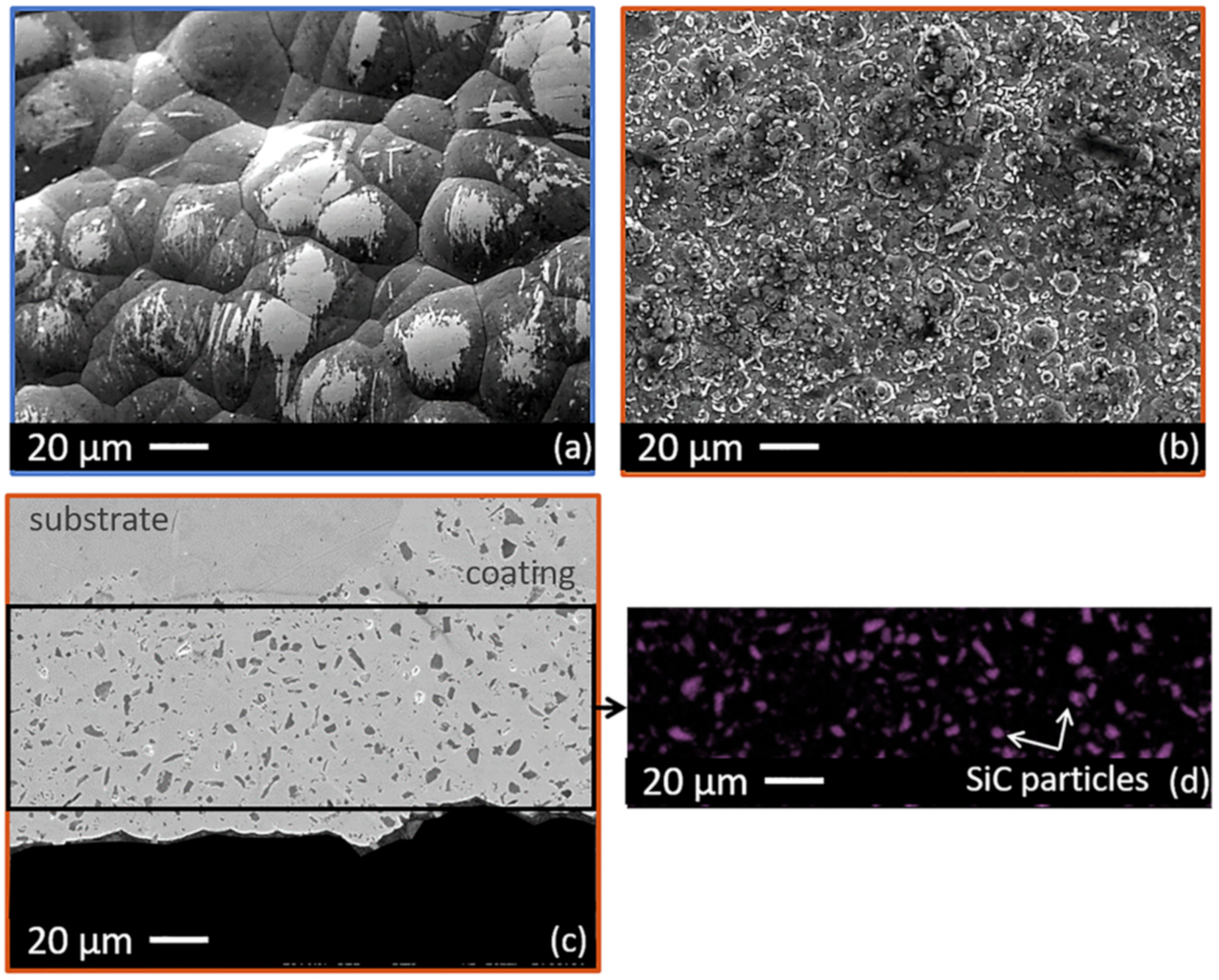
3.1. Coating Appearance and Morphology

Figure 4 shows the coated pin with both Ni–P and Ni–P/SiC. The Ni–P coating (Figure 4a) had a shiny appearance while the Ni–P/SiC was a matt coating (Figure 4b). This difference was attributed to the presence of SiC particles, which increased the surface roughness of the coatings and therefore changed the reflection of the light.
The morphology of the coatings on the surface of the pin can be seen in Figure 5. Figure 5a demonstrates a nodular morphology for Ni–P coating. In contrast, by adding SiC particles, the morphology was changed to smaller nodules than those in Ni–P (Figure 5b). A cross-sectional image of the composite coating (Figure 5c) exhibited the SiC particles distributed homogeneously along the coating thickness, as highlighted in the EDS map in Figure 5d. According to the SEM cross-section image, it was evident that SiC particles agglomerated during the coating process.
The composition of the surface of the coatings was measured by EDS, and the results are listed in Table 2. Both Ni–P and Ni–P/SiC coating had more than 12 wt.% of P, and they were categorised as Ni high-P coatings. The addition of SiC particles slightly reduced the P content of the coating. This reduction was not observed in the previous study [25].
Table 2 also lists the CE values of the exposition that was not affected by the addition of SiC particles.

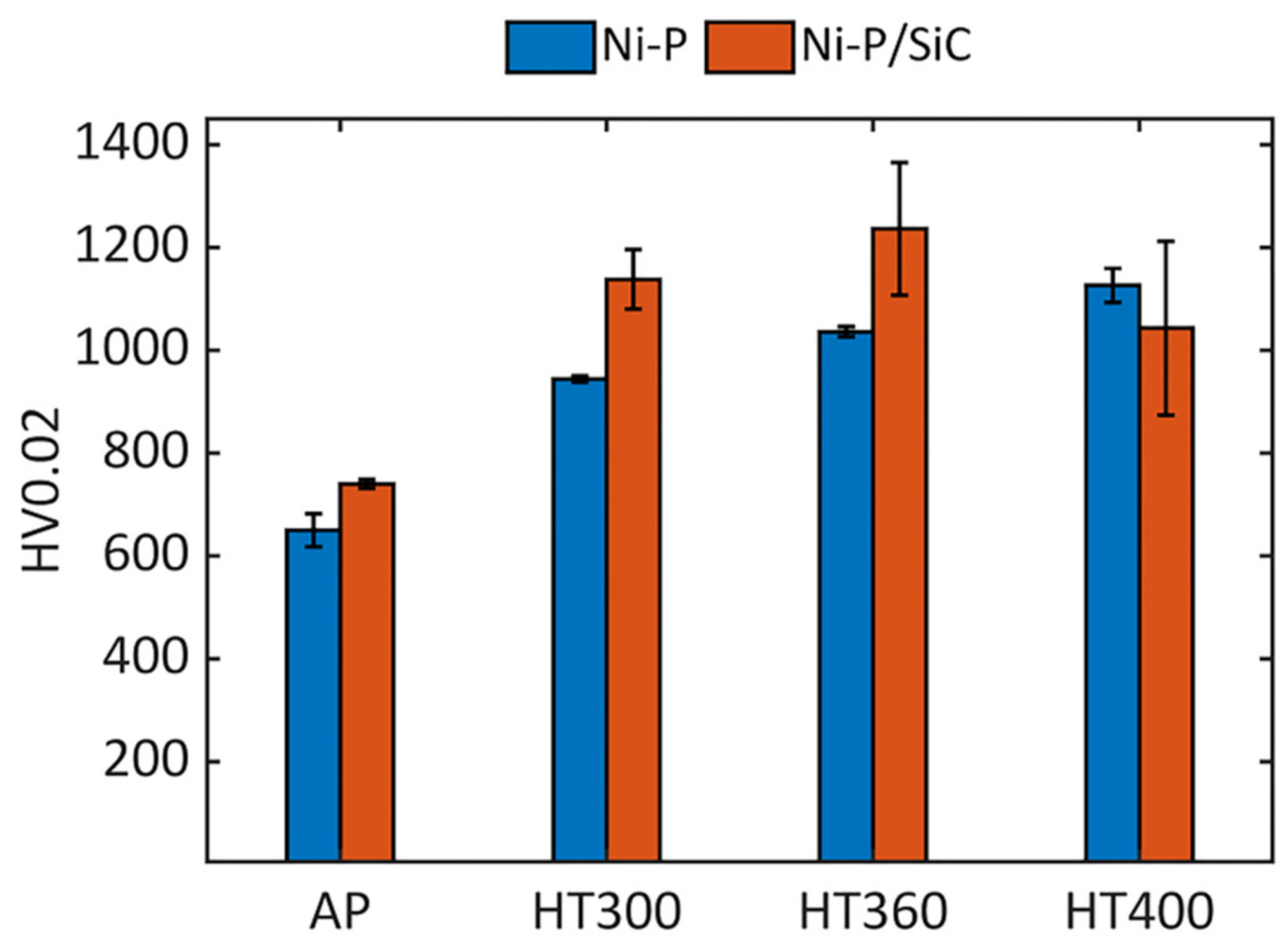
3.2. Coatings Hardness
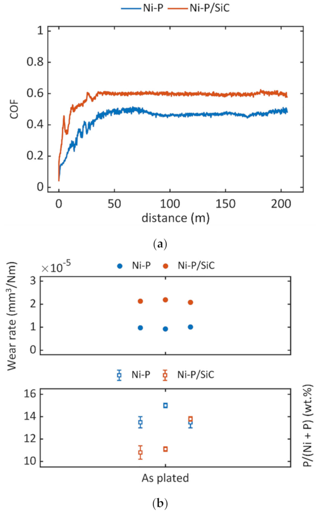
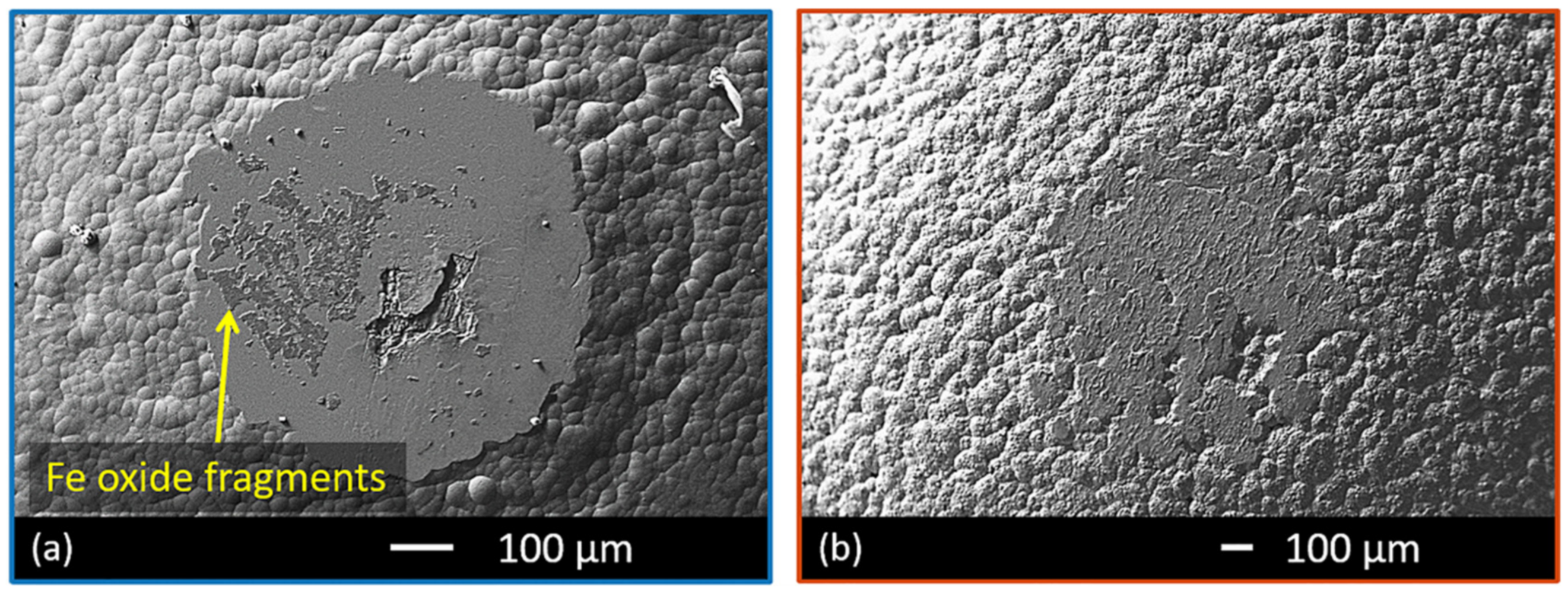
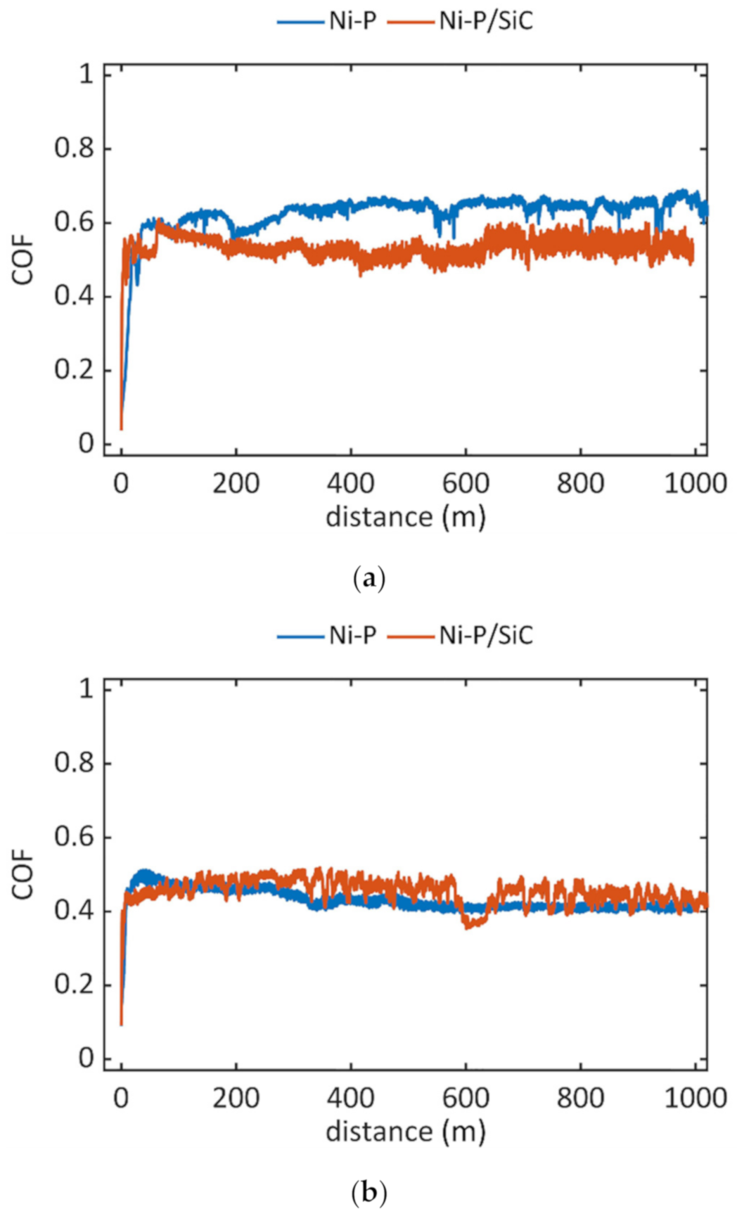
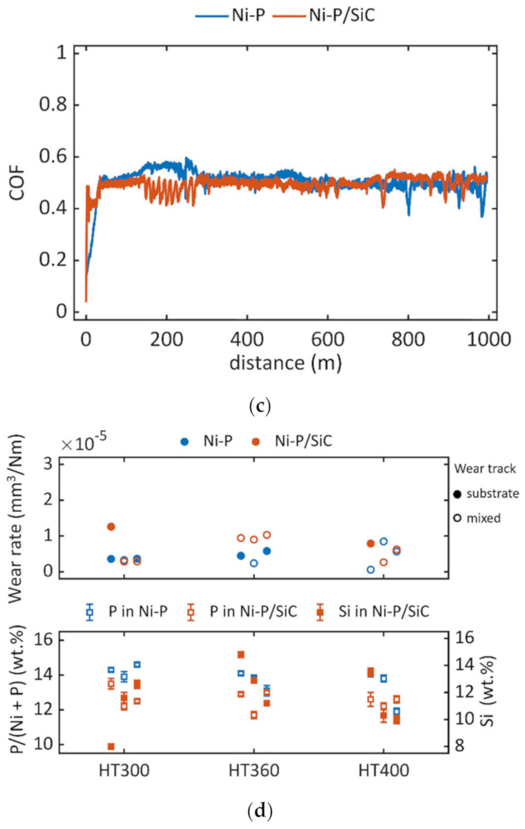
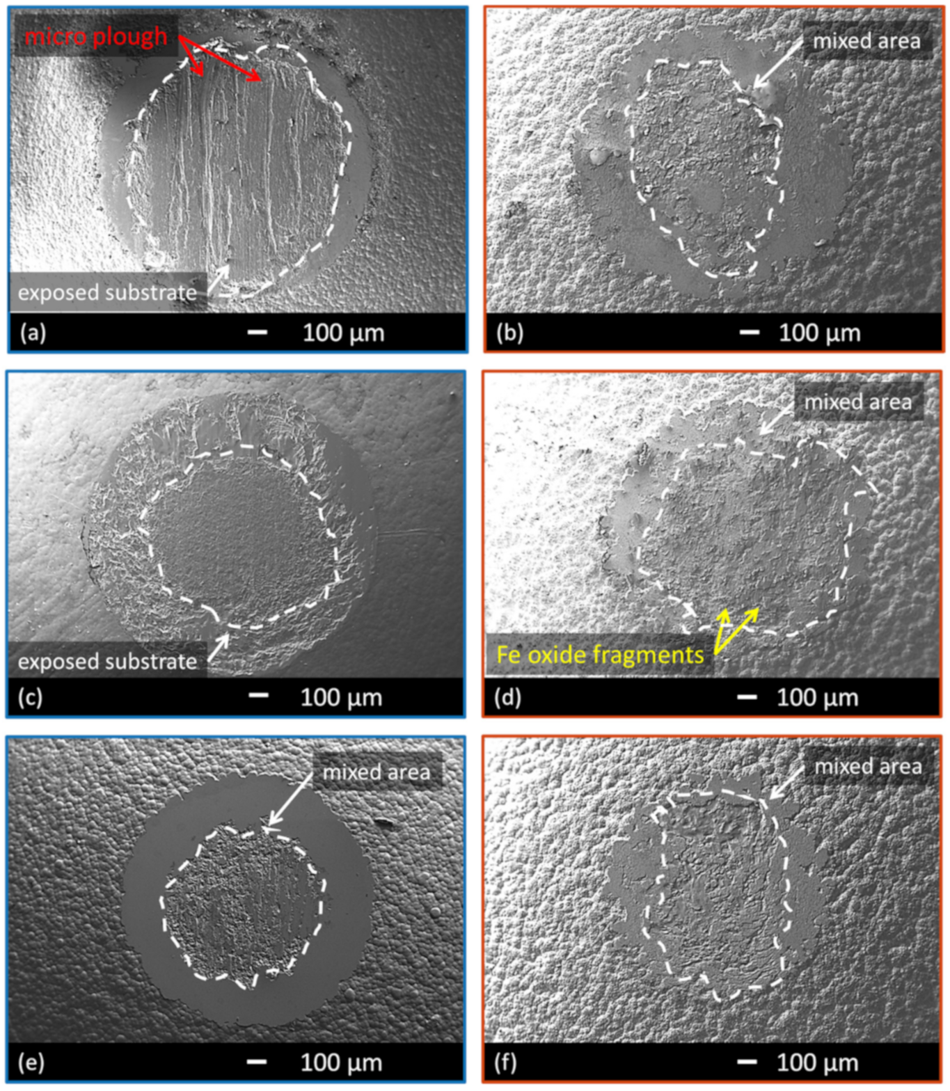
Coatings hardness was measured by Vickers indenter on the cross-section of the coatings, and the results are shown in Figure 6. Ni–P coating had 650 ± 30 HV0.02 and the addition of SiC particles increased the hardness values of 15% to 740 ± 10 HV0.02. However, heat treatment had more impact on enhancing the hardness values of these coatings. The maximum hardness in Ni–P coating was 1130 ± 30 HV0.02 achieved by HT400, while HT360 resulted in the maximum hardness of Ni–P/SiC coatings, 1240 ± 130 HV0.02.

3.3. Wear

Coefficient of friction (COF) trends and wear rate of as-plated samples are represented in Figure 7. The COF evolution (Figure 7a) differed significantly with the presence of SiC particles. The average COF value for the Ni–P coating was 0.4, and it increased to 0.6, with the presence of SiC particles. Figure 7a shows one curve for each condition, the closest to the average, representing all tested samples. The wear rates (Figure 7b) did not differ significantly in the same condition, as all values are ~10−5 mm3/Nm for the pure coating and ~2 × 10⁻⁵ mm3/Nm for the composite ones. Figure 7b gives the correspondent P and Si content on the pin tip for each wear rate value, the changes were not significant to influence the wear rate.
Representative wear tracks of the as-plated samples are depicted in Figure 8a for the Ni–P coatings, and Figure 8b for the composite ones. The yellow arrow in Figure 8a points at the residual layers of Fe oxides, coming from the antagonist, that adhere to the wear track. The representative wear track in Ni–P coating (Figure 8a) has a diameter of ~600 μm, smaller than the one of Ni–P/SiC coating (Figure 8b) with a diameter of ~800 μm. This observation mirrors the comparison of wear rate values in Figure 7b. In all cases, the substrate was not reached during the wear test.
Figure 9 depicts the COF evolution and wear rate of heat-treated samples. For HT300 samples (Figure 9a), the presence of SiC particles determined a slight decrease in the average COF, from ~0.65 to ~0.5. On the contrary, the COF curves reached the stable state at the same value for pure and composite coating in HT360 (Figure 9b) and HT400 (Figure 9c) treatments. Figure 9d gives the correspondent P and Si content on the pin tip for each sample as even small changes could influence the precipitation during the HT.
Figure 10 depicts the representative wear tracks for pure and composite coatings in each heat-treated condition: HT300 (Figure 10a,b), HT360 (Figure 10c,d) and HT400 (Figure 10e,f). In some cases the substrate steel was reached during wear, as visible for example in Figure 10a; in others, the wear track presented a mixed surface, characterised by substrate, coating residuals and Fe oxides originated from the antagonist (Figure 10d).
No specific trends were evident, as summarised in Table 3, although the substrate was reached more times with the pure coatings than with the composite ones. The different occurrence can be ascribed to local features, like the local thickness of the coating.

4. Discussion

4.1. As-Plated Coatings

Addition of SiC particles reduced the P content of the coating by 10%, although this reduction was not seen in the previous study [25]. This decrease can be related to the significant amount of co-deposited SiC, around 11 wt.% in this study. It has been reported that for Ni plating at low pH, SiC particles enhance the hydrogen (H2) evolution by absorbing protons on their surfaces [26,27] and consequently, results in increased hydrogen evolution. Therefore, the nascent H2 required for reducing P source to phosphine (according to the indirect reactions) [28] is decreased, hence reducing the P content in the coating. Besides, a CE reduction is expected by the P decrease in the coatings due to the H2 catalysis by SiC particles. In this study, the CE for Ni–P and Ni–P/SiC coatings were comparable, as seen in Table 2.
The wear mechanism involved in these coatings consisted of abrasion and tribo-oxidation. Abrasive wear was dominant in the early stages of contact. Then, the formation of Fe-based oxides led to tribo-oxidation. According to EDS measurements, the oxide layers were present in both pure and composite coatings, with no significant difference in the composition. The presence of the Cr signal confirmed that these oxides formed at expenses of the 100Cr6 antagonist. The COF evolution stabilised at a higher value for the composite coatings than the pure ones, as represented in Figure 7a. These results were mirrored by the wear rates in Figure 7b and suggested that the SiC particles determined an increase of friction in the system. Comparing the two wear tracks in Figure 8a,b, the SiC particles also acted as the third body in abrasive wear. They determined a rough appearance of the wear track. The SiC agglomerations are exposed by coating wear and can be easily disrupted during the sliding under load, leading to a spread of particles between the coating and the antagonist. In this case, the presence of Fe oxides mitigated the abrasive action of the ceramic particles, without fully compensating it. The steady-state COF values did not align with the results from Aslanyan et al. [21] that obtained similar COF trends for both Ni–P and Ni–P/SiC coatings in a system with corundum (Al2O3) as the antagonist. Nevertheless, the difference between these results can be expected, given the significant role of the antagonist. Similar observations hold for the work by Aghaie et al. [29], that tested as-plated Ni–P/SiC against copper (Cu). The authors reported a COF in the 0.5–0.7 range for the initial 200 m, with fluctuation peaks, and these values align with the present study despite the different wear system. They also observed the pull-out of SiC particles from the matrix as wear proceeded, and those particles determined abrasion at expenses of the coating. Chang et al. [19] compared Ni–P and Ni–P/SiC coatings against zirconium oxide (ZrO2), observing a higher volume loss for the composite coating than the pure one, as well as a higher COF. These results are comparable with what reported in the present study with a different wear system. In summary, different coupling systems can lead to different wear mechanisms, and in the present study the formation of Fe oxides coming from the antagonist influenced the response of coatings to wear.

4.2. Heat-Treated Coatings

The hardness values in Figure 6 support the hypothesis that crystallisation and precipitation happened at a lower temperature in Ni–P/SiC coating than Ni–P one. Since all the tested samples had similar composition (similar P and SiC wt.%), the hardness of the coatings in Figure 6 was related to the different heat treatments. At 400 °C, after reaching the maximum hardness, grain growth started, and so hardness was reduced. Hence, SiC particles did not influence the grain boundaries migration in this case.
The wear mechanisms consisted of abrasion and tribo-oxidation for the heat-treated coatings, similarly to the as-plated coatings. The presence of SiC particles determined a slight difference in the COF evolution for the HT300 samples (Figure 9a). At the same time, it did not influence the COF values for HT360 (Figure 9b) and HT400 (Figure 9c) samples. Nevertheless, the composite coatings presented noisier curves because of the presence of reinforcing particles acting as third body once exposed and pulled-out from the matrix. For what concerns wear rates, it is necessary to distinguish the samples with wear tracks that reached the substrate (solid circles in Figure 9d) from the ones that presented a mixed surface (empty circles in Figure 9d).
The wear tracks of HT300 pure coatings showed the substrate presented a wear rate of ~3.5 × 10⁻⁶ mm3/Nm. Micro-plough traces were evident on the surfaces, and due to the fragmentation of coating during sliding (Figure 10a). The lubricant role of Fe oxides did not compensate for the abrasive action of such fragments on the substrate. In the cases with substrate exposed, the thickness of the coating was ~26 and ~34 μm, respectively. These values were estimated from the dimension of the annular section of the coating that characterised the wear track. The sample that presented a mixed surface also presented a slightly lower P than the other samples. For the HT300 composite coatings, the wear track presented a mixed surface, with the simultaneous presence of substrate, Fe oxides, and residual coating in the centre (Figure 10b). The higher hardness of composites (Figure 6) and SiC particles’ presence as the third body was mitigated by the Fe oxides. The one sample that showed the substrate had a thickness of ~27 μm. The substrate surface was smooth and regular, resulting from a homogeneous abrasion due to the action of SiC particles. It was also the sample that showed the higher content of P with respect to the other ones. These observations align well with the COF trends of Figure 9a since the presence of Fe oxides did not prevent micro-ploughing mechanisms in pure coatings but showed a beneficial effect for the composite coatings. Kong et al. [30] also reported similar COF values for electroless Ni–P coatings treated at 300 °C and observed abrasive wear mechanisms, although the antagonist material was not stated.
Moving to the pure coatings after HT360 treatment, the substrate emerged in the wear track for two samples, and the wear rate values are in the 4.5× 10⁻⁶–5.8 × 10⁻⁶ mm3/Nm range. The centre of wear tracks appeared uniform and regular (Figure 10c), thanks to the Fe oxide’s presence that mitigated the damaging effect of coating fragments. In these cases, the coating thickness was estimated at ~35 and ~48 μm. One sample presented a mixed surface. In composite coatings, all samples presented a mixed surface on the wear track, with the co-presence of residual coating and Fe oxides. In all these cases, the wear rate was ~10−5 mm3/Nm, higher than the average value obtained for the pure ones. These results accord well with the hardness values, significantly higher for the Ni–P/SiC coating than the pure ones after the HT360 treatment (Figure 6). Nevertheless, these results are not mirrored by the COF trends in Figure 9b, comparable for both pure and composite coatings. Kong et al. [30] investigated electroless Ni–P coatings and in particular the influence of the heat-treatment on the wear response. They reported that the coatings treated at 350 °C present the maximum hardness of ~6100 MPa. The friction coefficient is 0.8. This is also the condition that determines the change from abrasive wear, for temperatures below 350 °C, to adhesive wear for temperatures higher than 350 °C.
The results for the HT400 treated samples were different. The Ni–P coatings presented a mixed surface on the wear track in all cases, as depicted in Figure 10e. The wear rate values are lower than ~10−5 mm3/Nm, and values in the same range were found for the composite coatings, as represented in Figure 10f. One sample presented the substrate, and the estimated thickness was ~38 μm. The appearance is comparable with the other samples that reached the substrate because similar Fe oxides originated from the antagonist. The mechanism is still abrasive, and this result differs from what reported by Kong et al. [30] on electroless Ni–P treated at 400 °C. Prabu Ram et al. [17] also tested electroless Ni–P after heat treatment performed at 400 °C against AISI 440C steel. They observed the formation of an iron oxide layer that adheres on the coatings and has a strong influence on the wear mechanism. Delamination of the coating was not observed, and these results are in line with the present study. The wear system is different, but the similarities are due to the nature of the Fe-based antagonist materials. The overlapping of wear rate values for the two conditions mirrors the COF trends in Figure 9c and the similar hardness values measured for the HT400 samples (Figure 6). The presented results for the HT400 treatment agree with Aslanyan et al. [21] despite the different coupling system. They reported similar COF trends for both pure and Ni–P/SiC coatings after 1 h at 420 °C. Using corundum as the antagonist, the authors reported a wear volume loss higher for the composite coatings than the pure ones. They attributed it to the pull out of SiC particles during wear, that contributed to the abrasion of the material. The same observations apply to the non-abrasive coupling of the present study with 100Cr6 steel. On the other hand, Chang et al. [19] reported different results with zirconium oxide as antagonist. After the heat treatment carried out at 400 °C for 1 h, the pure coating presented a higher volume loss than the composite one. Similarly, the average COF was slightly higher for the Ni–P coating. The authors attributed these results to the formation of Ni5Si2 during heat treatment, that increases ductility due to the small angle phase boundary. A similar behaviour was not observed with the samples of the present study.
The presence of reinforcing particles did not alter the COF values for HT360 and HT400 conditions; however, it affected the wear rate, particularly for the HT360 samples. It is critical to underline that the influence of heat treatment is determined by the P content within the high-P family. Ahmadkhaniha et al. [23] recently clarified that small variations in the P content, within 10 wt.%–16 wt.%, led to different mechanical properties after heat treatment. Thus, the P content is the dominant variable, yet it cannot be controlled during the production process, either electrodeposited or electroless. Nevertheless, the samples of the present study are of interest because they represent the real condition in production systems, with P content in the 10 wt.%–16 wt.% range. The difficulties in optimising specific heat treatments stem from the variation of composition obtained in real production.

5. Conclusions

The present work investigated the wear behaviour of Ni–P and Ni–P/SiC coatings in the as-plated condition and after different heat treatments. The antagonist was a 100Cr6 steel, representative of non-abrasive systems. The interest of the present study was the representation of the real industrial production of Ni–P coatings and the related variations in P content. The aim of the present work was to differentiate the contributions of SiC addition and heat treatment on the wear properties of Ni–P coatings, to find the optimum condition that minimizes the wear rate.
The presence of SiC particles significantly influenced the COF and the wear rate of the as-plated coatings, despite the limited influence in increasing hardness. The presence of Fe oxides, originated in the tribo-oxidation wear mechanisms on the antagonist side, did not completely mitigate the ceramic particles’ abrasive action in the composite coatings. These presented higher COF and wear rate than the pure ones.
After heat treatment, the maximum hardness of pure coatings was after 1 h at 400 °C (HT400), while the maximum hardness of composite coatings was after 2 h at 360 °C (HT360). During wear tests, the COF trends reported a difference between pure and composite coatings only in the HT300 condition (300 °C for 2 h). In other cases, the COF stabilised at similar values. The wear mechanisms involved were mainly abrasion and tribo-oxidation, with the formation of lubricant Fe oxides at expenses of the antagonist steel. Micro-plough also occurred for the pure HT300 samples, and Fe oxides combined with SiC particles mitigated it in the composite coating. The COF trends were not mirrored by hardness and wear rates in the HT360 condition, that shown distinct values.

Author Contributions

Conceptualisation, C.Z. and M.M.; methodology, C.Z., D.A., L.L., and A.F.; resources, C.Z. and M.M.; data curation, D.A., L.L., and F.B.; writing—original draft preparation, D.A., L.L., and F.B.; writing—review and editing, A.F., C.Z., and M.M.; supervision, C.Z. and M.M. All authors have read and agreed to the published version of the manuscript.

Funding

This research received no external funding.

Institutional Review Board Statement

Not applicable.

Informed Consent Statement

Not applicable.

Data Availability Statement

The data presented in this study are available on reasonable request from the corresponding author. The data are not publicly available due to privacy.

Acknowledgments

No acknowledgements are needed.

Conflicts of Interest

The authors declare no conflict of interest.

References

  1. Sahoo, P.; Das, S.K. Tribology of electroless nickel coatings—A review. Mater. Des. 2011, 32, 1760–1775. [Google Scholar] [CrossRef]
  2. Agarwala, R.C.; Agarwala, V. Electroless alloy/composite coatings: A review. Front. Mater. Sci. 2005, 28, 475–493. [Google Scholar] [CrossRef]
  3. Lelevic, A.; Walsh, F.C. Electrodeposition of Ni–P alloy coatings: A review. Surf. Coat. Technol. 2019, 369, 198–220. [Google Scholar] [CrossRef]
  4. Mahidashti, Z.; Aliofkhazraei, M.; Lotfi, N. Review of nickel-based electrodeposited tribo-coatings. Trans. Indian Inst. Met. 2018, 71, 257–295. [Google Scholar] [CrossRef]
  5. ASTM B733-15 Standard Specification for Autocatalytic (Electroless) Nickel-Phosphorus Coatings on Metal; ASTM International: West Conshohocken, PA, USA, 2015.
  6. Buchtík, M.; Kosár, P.; Wasserbauer, J.; Tkacz, J.; Doležal, P. Characterization of electroless Ni–P coating prepared on a wrought ZE10 magnesium alloy. Coatings 2018, 8, 96. [Google Scholar] [CrossRef] [Green Version]
  7. Berkh, O.; Zahavi, J. Electrodeposition and properties of NiP alloys and their composites—A literature survey. Corros. Rev. 1996, 14, 323–341. [Google Scholar] [CrossRef]
  8. Biswas, A.; Das, S.K.; Sahoo, P. A comparative study in microstructural and tribological aspects of phosphorus enriched electroless Ni–P and Ni–P–Cu coating. Mater. Today Proc. 2019, 1–6. [Google Scholar] [CrossRef]
  9. Zanella, C.; Lekka, M.; Bonora, P.L. Influence of the particle size on the mechanical and electrochemical behaviour of micro- and nano-nickel matrix composite coatings. J. Appl. Electrochem. 2009, 39, 31–38. [Google Scholar] [CrossRef]
  10. Ahmadkhaniha, D.; Zanella, C. The effects of additives, particles load and current density on codeposition of SiC particles in NiP nanocomposite coatings. Coatings 2019, 9, 554. [Google Scholar] [CrossRef] [Green Version]
  11. Gao, J.; Liu, L.; Wu, Y.; Shen, B.; Hu, W. Electroless Ni–P–SiC composite coatings with superfine particles. Surf. Coat. Technol. 2006, 200, 5836–5842. [Google Scholar] [CrossRef]
  12. Sarret, M.; Müller, C.; Amell, A. Electroless NiP micro- and nano-composite coatings. Surf. Coat. Technol. 2006, 201, 389–395. [Google Scholar] [CrossRef]
  13. Metzger, M.; Ott, R.; Pappe, G.; Schmidt, H. Articles Having Electroless Metal Coatings Incorporating Wear-Resisting Particles Therein. U.S. Patent 3,753,667A, 21 August 1973. [Google Scholar]
  14. Sliem, M.H.; Shahzad, K.; Sivaprasad, V.N.; Shakoor, R.A.; Abdullah, A.M.; Fayyaz, O.; Kahraman, R.; Umer, M.A. Enhanced mechanical and corrosion protection properties of pulse electrodeposited NiP–ZrO2 nanocomposite coatings. Surf. Coat. Technol. 2020, 403, 126340. [Google Scholar] [CrossRef]
  15. Tamilarasan, T.R.; Rajendran, R.; Siva shankar, M.; Sanjith, U.; Rajagopal, G.; Sudagar, J. Wear and scratch behaviour of electroless Ni–P-nano-TiO2: Effect of surfactants. Wear 2016, 346–347, 148–157. [Google Scholar] [CrossRef]
  16. Karthikeyan, S.; Vijayaraghavan, L.; Madhavan, S.; Almeida, A. Study on the mechanical properties of heat-treated electroless NiP coatings reinforced with Al2O3 nano particles. Metall. Mater. Trans. A Phys. Metall. Mater. Sci. 2016, 47, 2223–2231. [Google Scholar] [CrossRef]
  17. Prabu Ram, G.; Karthikeyan, S.; Emmanuel Nicholas, P.; Sathya Sofia, A. Dry sliding wear behavior of electroless NiP and NiP–Al2O3 composite coatings. Mater. Today Proc. 2020. [Google Scholar] [CrossRef]
  18. De Hazan, Y.; Zimmermann, D.; Z’Graggen, M.; Roos, S.; Aneziris, C.; Bollier, H.; Fehr, P.; Graule, T. Homogeneous electroless Ni-P/SiO2 nanocomposite coatings with improved wear resistance and modified wear behavior. Surf. Coat. Technol. 2010, 204, 3464–3470. [Google Scholar] [CrossRef]
  19. Chang, C.S.; Hou, K.H.; Ger, M.-D.; Chung, C.K.; Lin, J.F. Effects of annealing temperature on microstructure, surface roughness, mechanical and tribological properties of Ni- and Ni–P/SiC films. Surf. Coat. Technol. 2016, 288, 135–143. [Google Scholar] [CrossRef]
  20. Apachitei, I.; Tichelaar, F.D.; Duszczyk, J.; Katgerman, L. The effect of heat treatment on the structure and abrasive wear resistance of autocatalytic NiP and NiP–SiC coatings. Surf. Coat. Technol. 2002, 149, 263–278. [Google Scholar] [CrossRef]
  21. Aslanyan, I.R.; Bonino, J.P.; Celis, J.P. Effect of reinforcing submicron SiC particles on the wear of electrolytic NiP coatings: Part 1. Uni-directional sliding. Surf. Coat. Technol. 2006, 200, 2909–2916. [Google Scholar] [CrossRef]
  22. UNI EN ISO 683-4:2018 Heat-Treatable Steels, Alloy Steels and Free-Cutting Steels—Part 4: Free-Cutting Steels; UNI: Milano, Italy, 2018.
  23. Ahmadkhaniha, D.; Eriksson, F.; Zanella, C. Optimizing heat treatment for electroplated NiP and NiP/SiC coatings. Coatings 2020, 10, 1179. [Google Scholar] [CrossRef]
  24. EN ISO 683-17 Heat-Treated Steels, Alloy Steels and Free-Cutting Steels—Part 17: Ball and Roller Bearing Steels; ISO: Geneva, Switzerland, 2015.
  25. Ahmadkhaniha, D.; Eriksson, F.; Leisner, P.; Zanella, C. Effect of SiC particle size and heat-treatment on microhardness and corrosion resistance of NiP electrodeposited coatings. J. Alloys Compd. 2018, 769, 1080–1087. [Google Scholar] [CrossRef]
  26. Pavlatou, E.A.; Stroumbouli, M.; Gyftou, P.; Spyrellis, N. Hardening effect induced by incorporation of SiC particles in nickel electrodeposits. J. Appl. Electrochem. 2006, 36, 385–394. [Google Scholar] [CrossRef]
  27. Zoikis-Karathanasis, A.; Pavlatou, E.A.; Spyrellis, N. Pulse electrodeposition of Ni–P matrix composite coatings reinforced by SiC particles. J. Alloys Compd. 2010, 494, 396–403. [Google Scholar] [CrossRef]
  28. Hansal, W.E.G.; Sandulache, G.; Mann, R.; Leisner, P. Pulse-electrodeposited NiP–SiC composite coatings. Electrochim. Acta. 2013, 114, 851–858. [Google Scholar] [CrossRef]
  29. Aghaie, E.; Najafi, A.; Maleki-Ghaleh, H.; Mohebi, H. Effect of SiC concentration in electrolyte on Ni–SiC composite coating properties. Surf. Eng. 2013, 29, 177–182. [Google Scholar] [CrossRef]
  30. Kong, D.; Wang, J.; Fu, G.; Liu, H. Friction and wear performances of Ni–P coatings by chemical plating after crystallization treatment. Rare Metal Mater. Eng. 2015, 44, 1314–1319. [Google Scholar]
Figure 1. Dimensions of the pin in mm.
Coatings 11 00180 g001
Figure 2. Configurations of the deposition cells for (a) pure coatings and (b) composite coatings.
Coatings 11 00180 g002
Figure 3. Point clouds of the pin tip surface from the profilometer acquisitions: (a) unworned; (b) worned, at the end of the wear test.
Coatings 11 00180 g003
Figure 4. Coated pins with (a) Ni–P and (b) Ni–P/SiC coatings.
Coatings 11 00180 g004
Figure 5. SEM image of (a) Ni–P surface and (b) Ni–P/SiC surface; (c) SEM image of the cross-section of Ni–P/SiC coating; and (d) EDS map of Si element related to (c).
Coatings 11 00180 g005
Figure 6. Microhardness valued of Ni–P and Ni–P/SiC coatings before and after heat treatments. Error bars represent standard deviation.
Coatings 11 00180 g006
Figure 7. As-plated samples: (a) coefficient of friction (COF) evolution; (b) wear rate and P and Si content.
Coatings 11 00180 g007
Figure 8. Wear tracks of the as-plated samples: (a) Ni–P; (b) Ni–P/SiC.
Coatings 11 00180 g008
Figure 9. Heat-treated samples: (a) COF evolution of HT300; (b) COF evolution of HT360; (c) COF evolution of HT400; (d) wear rate and P content.
Coatings 11 00180 g009aCoatings 11 00180 g009b
Figure 10. Wear tracks, after acetone rinsing, of the heat-treated samples: for HT300 treatment, (a) Ni–P and (b) Ni–P/SiC; for HT360 treatment, (c) Ni–P and (d) Ni–P/SiC; for HT400 treatment, (e) Ni–P and (f) Ni–P/SiC.
Coatings 11 00180 g010
Table 1. Heat treatment conditions.
Heat TreatmentTemperature (°C)Time (h)
HT300300 °C2
HT360360 °C2
HT400400 °C1
Table 2. Surface composition and current efficiency (CE) of Ni–P and Ni–P/SiC coatings.
CoatingP/(P + Ni) (wt.%)SiC (wt.%)CE
Ni–P13.9 ± 0.0846% ± 8%
Ni–P/SiC12.6 ± 0.0311.3 ± 0.0545% ± 5%
Table 3. Wear rate and surface condition of the wear track of Ni-P and Ni-P/SiC coatings.
CoatingRepetitionHT300HT360HT400
Wear Rate
(mm3/Nm)
SurfaceWear Rate
(mm3/Nm)
SurfaceWear Rate
(mm3/Nm)
Surface
Ni–Pi3.6 × 10−6substrate4.5 × 10−6substrate5.9 × 10−7mixed
ii3.3 × 10−6mixed2.4 × 10−6mixed8.5 × 10−6mixed
iii3.7 × 10−6substrate5.8 × 10−6substrate5.7 × 10−6mixed
Ni–P/SiCi1.2 × 10−5substrate9.4 × 10−6mixed7.9 × 10−6substrate
ii2.9 × 10−6mixed9.0 × 10−6mixed2.7 × 10−6mixed
iii2.9 × 10−6mixed1.0 × 10−5mixed6.2 × 10−6mixed
Publisher’s Note: MDPI stays neutral with regard to jurisdictional claims in published maps and institutional affiliations.

