
Sialon and Alumina Modified UV-Curable Coatings with Improved Mechanical Properties and Hydrophobicity


1
Faculty of Chemical Technology, Poznan University of Technology, 60-965 Poznan, Poland
2
Department of Mechanical Engineering, Poznan University of Technology, 60-965 Poznan, Poland
3
Sustainable Polymer Chemistry, Department of Molecules & Materials, Faculty of Science and Technology, University of Twente, 7522 NB Enschede, The Netherlands
*
Author to whom correspondence should be addressed.
Coatings 2021, 11(11), 1424; https://doi.org/10.3390/coatings11111424
Submission received: 15 October 2021
/
Revised: 12 November 2021
/
Accepted: 16 November 2021
/
Published: 22 November 2021
Abstract
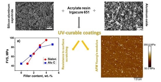
:This article describes the modification of UV-curable coatings with silicon aluminum oxynitride (Sialon) and aluminum oxide (Alu C), which improve the hydrophobicity of the coating surface and the scratch hardness. The contact angle is greater due to surface roughness being enhanced with inorganic fillers. Improved scratch resistance results from the formation of a sliding layer triggered by the diffusion of Sialon or alumina on the coating surface. One can observed an increase in the surface hydrophobicity as well as in the scratch hardness (up to 100%) when small amounts (5 wt.%) of the inorganic compounds are added. Imaging microscopies, i.e., SEM, OM, and AFM (with nanoscopic Young’s modulus determination), revealed the good distribution of both types of fillers in the studied matrix.
1. Introduction
Photopolymerization (photochemically initiated polymerization) is a technique that is used in various branches of industry (microelectronics, optoelectronics, dentistry, medicine, 3D printing, nail varnishes, adhesives, and protective coatings) [1,2,3,4,5,6,7]. It enables polymerization to occur at room temperature within a very short amount of time. It only takes a few seconds or a few minutes to finish a product [8,9,10,11,12]. Under the influence of ultraviolet (UV) or visible light (VIS), the photoinitiator breaks down and forms active centres (free radicals, ions), initiating polymerization [13,14,15,16]. The photopolymerization technique allows products of various shapes (the process takes place only in areas exposed to light) to be created using compositions that do not contain any volatile solvents, while the energy consumption is low, and the process is highly controllable [7]. In fact, the reaction takes place only during exposure to light (when the source of light is turned off, the initiation is interrupted) [17].
The protective coating industry is one of the oldest and most common applications of photopolymerization. Technical coatings are often used to enhance mechanical (i.e., hardness or abrasion resistance), electrical, and thermal properties [18]. Varnish compositions resulting from the polymerization of acrylic and styrene monomers are applied both to metallic and wooden substrates. The adhesion of adhesives/coatings is influenced by the following key factors: shape of the surface roughness, size of the roughened surface, and the presence of impurities or voids. The photocurable compositions used in this branch are composed of mixtures of acrylic polyesters with various multifunctional monomers and fillers. Photopolymerized coatings are resistant to organic solvents, chemicals, heat, and atmospheric factors [19]. They are used as coatings for cars, machines, and other technical devices.
The selection of the components to be used in a photocurable composition depends on the expected properties of the finished product and its intended use [20]. This composition usually consists of the following basic components: a mixture of monomers (a multifunctional telechelic oligomer or polymer and a low-molecular weight reactive diluent), an initiating system, and various additives, such as stabilisers, fillers, colouring agents (pigments, dyes), anti-electrostatic compounds, adhesion promoters, etc.
The technology developments are noticed more often during the production of high-quality varnishes [21]. These coatings can be modified with inorganic fillers. These are inert substances that are added into the polymer matrix to improve its physicochemical and mechanical properties. Fillers increase the material hardness, resistance to abrasion, and the effect of various aggressive environments. They also improve the tensile strength and reduce shrinkage during curing. Superhydrophobicity is a very important feature of good varnish coatings. The contact angle of the surface of superhydrophobic products is greater than 150°; thus, they repel water from their surfaces [22]. There are also other advantages. Varnishes are resistant to destructive moisture, and they do not become dirty as quickly as other coatings do (drops of water immediately run off the surface and rinse off impurities).
Contemporary trends in industrial development are oriented towards the production of materials with better and often unique properties (e.g., surface and mechanical properties). Ecological aspects are simultaneously taken into account during the production of these materials. In order to achieve this goal, scientific and industrial institutions need to cooperate and only conduct not basic as well as application research. As photopolymerization and inorganic particles have numerous advantages, in the near future, the market for protective coatings may be dominated by photocurable varnishes and paints that have been modified with a new generation of fillers.
Continuing our investigations on the preparation and properties of photocurable composites containing a hybrid filler—Aerosil®COK 84 (Evonik Industries: Essen, Germany), which is a mixture of fumed silica Aerosil®200 and highly dispersed aluminum oxide in a 5:1 ratio [8], we have now launched research concerning a special fillers: Sialon (silicon aluminum oxynitride) and Alu C (aluminum oxide).
The name “Sialon” comes from the chemical symbols of the elements composing this material (silicon, aluminum, oxynitride). Sialon is a relatively new type of material that is able to combine the advantages of oxide ceramics with Al2O3 and anaerobics (nitride) containing Si3N4. While many studies have investigated the formation of polymer composites containing inorganic particles in a UV-induced process [23], there are no detailed reports on the photocuring behaviour of systems containing Sialon. It is generally known that the introduction of aluminum oxide into the composite significantly helps to increase polymer hardness and wear resistance [24]. The chemical properties of Sialon correspond to the chemically passive aluminium oxide (for example: high resistance to oxidation at elevated temperature), so in this article, we aim to compare the influence of both of these fillers.
Our article describes an attempt to modify photocurable varnish coatings with Sialon and aluminum oxide (Alu C) and to assess its influence on the mechanical and physicochemical properties of the input systems (materials without fillers) and the resulting varnish coatings. Compared to other classical varnish production methods, photopolymerization significantly reduced the production time (from hours to minutes), eliminated the low-boiling-point solvent that was not environmentally friendly, and reduced energy consumption because the process took place at ambient temperature. The compositions of the varnishes containing fillers and the production methods used to create the varnish coatings tested onwood-based material or aluminium can be used in the furniture industry (e.g., to produce and maintain furniture and parquets), in the paper industry (e.g., to impregnate paper), and in the transport industry (e.g., to paint cars, ships, and aircrafts). Our investigations allow us to compare the photocuring and physical behaviour of systems filled with Sialon and aluminum oxide and can help to design formulations and conditions for industrial applications. Sialon and Alu C compounds are assumed to be potential for used in the engineering of ceramic materials because of their excellent mechanical and thermal properties [25,26]; these fillers can be used for UV-curable polyacrylate-based composites for protective coatings, particularly in the woodworking industry. Light-cured coatings containing Sialon and Alu C have significant advantages over conventional production methods due to their broad properties, such as the material’s short curing time and low space requirements. This is the best filler dispersion method that can be used for varnish composition, and the process takes place in a solvent-free environment.
2. Experimental Section
2.1. Materials
The acrylate resin CN 3755 (difunctional acrylated amine synergist) was kindly donated by Sartomer (Arkema Group, Exton, PA, USA). According to the supplier, the product is meant for UV-curable coatings composed of wood and metal substrates. Additionally, according to the manufacturer, it offers good adhesion, toughness, excellent resistance properties, low yellowing, and very low pigment bleeding. The reactive diluent 1,6-hexanediol diacrylate (HDDA) and photoinitiator 2,2-dimethoxy-2-phenylacetophenone (Irgacure 651) were purchased from Sigma-Aldrich (St. Louis, MO, USA). Aluminum oxide (AEROXIDE® Alu C, Evonik Industries, Essen, Germany) is a fine-particulate, pure aluminium oxide with a high specific surface area of 85–115 m2/g and an average primary particle size of 13 nm. These fillers were kindly donated by Evonik (Evonik Industries, Essen, Germany). Sialon (Al6N6O2Si, 306.01 g/mol) was purchased from Sigma Aldrich (microsized particles, St. Louis, MO, USA). The fillers were dried at 110 °C for 2 h before use.
2.2. Varnish Coating Formation Methodology
2.2.1. Preparation of Varnish Compositions
The varnish compositions were prepared in 20 mL vials. At the first stage of the process, a composition consisting of CN 3755 resin and HDDA diluent was prepared at a weight ratio of 70:30. The compositions were dispersed in an ultrasonic bath for 2 h. Next, Sialon and Alu C were added at an adequate weight ratio to the resin and solvent, i.e., 0–5%. The samples were homogenised in an ultrasonic bath for about 24 h. When the filler reached a fine dispersion level in the resin, Irgacure 651 photoinitiator was added to the mass of the resin and diluent at a weight ratio of 3%. The compositions were dispersed in an ultrasonic bath for 2 h. Before the varnish compositions were applied onto a wooden substrate, they were homogenised for one minute in an Ultra-Turrax T18 basic homogeniser (IKA) equipped with a Rotor-Stator L004639 dispersing element. Due to the high acceleration, the substances were exposed to strong cutting forces, and the resulting turbulences enabled the optimal mixing of the composition.
2.2.2. Coating of Substrates
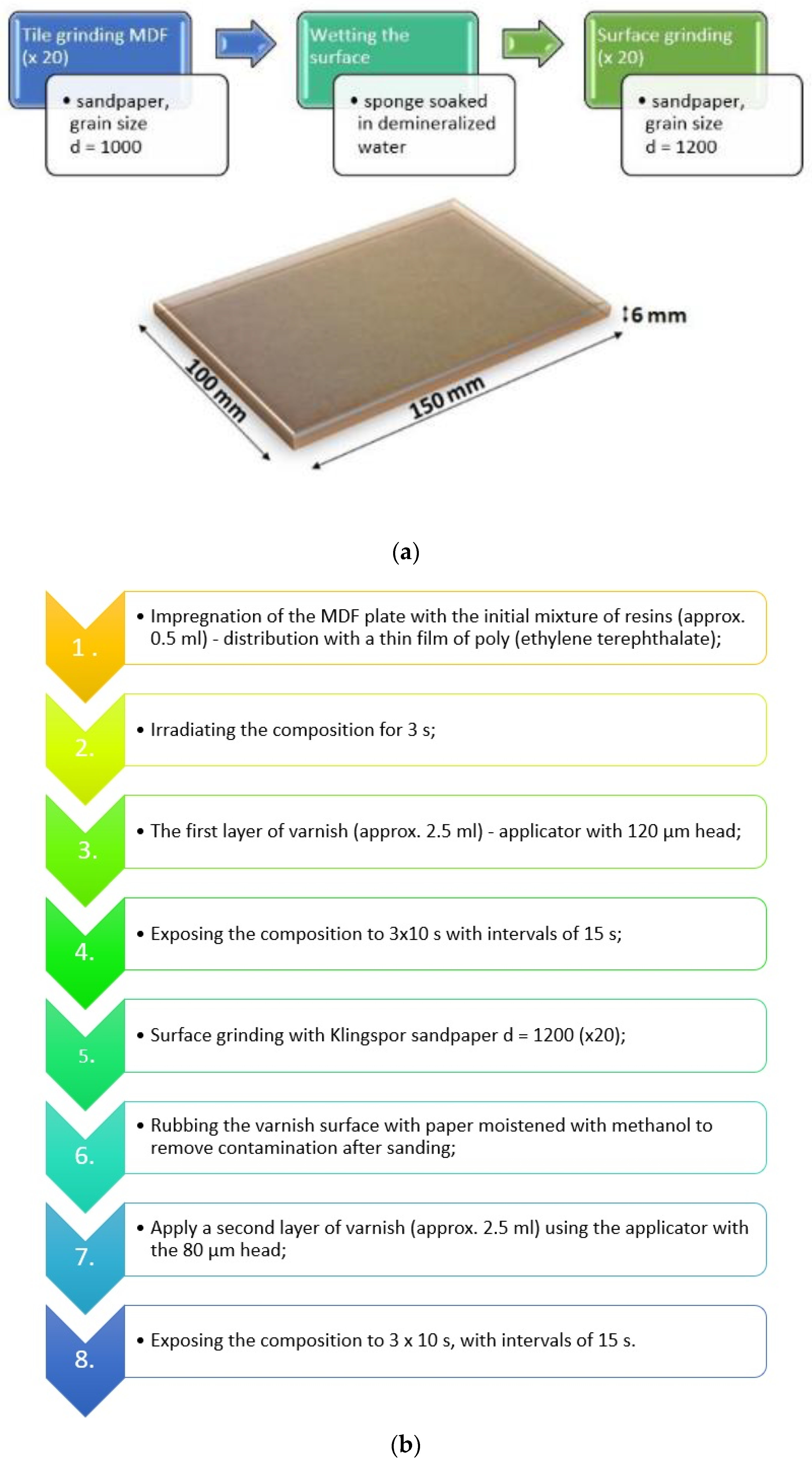
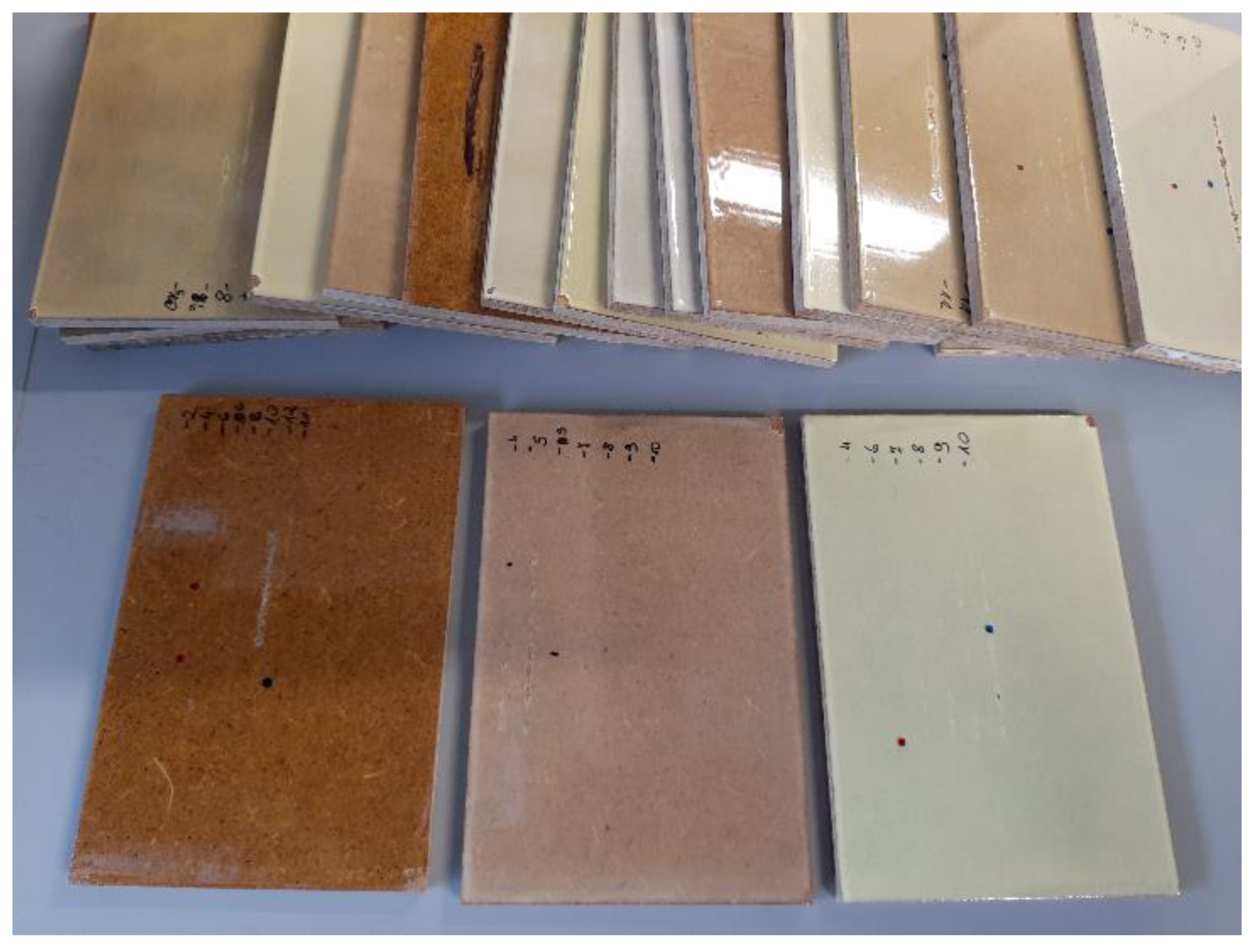
We used a wood-based substrate (MDF) as a model surface for coating. Figure 1 shows the schematics of coating of substrate. Before coating, the surface was ground with 1000- and 1200-grit sandpaper, cleaned, and covered with 0.5 mL of the formulation (Figure 1a). The resulting pre-coating was cured during one pass under a UV lamp in a DYMAX UVC-5 Conveyor System (Dymax, Torrington, CT, USA) (duration: 3 s, belt speed: 7 m/min). Then, the first 120-μm-thick layer of the liquid formulation was applied with a spiral applicator, and it was photocured by three passes (3 × 10 s) under a UV lamp (belt speed: 1.4 m/min) with a 15-s pause after each pass. The first cured layer of the coating was ground with 1200-grit sandpaper and cleaned with paper wetted with methanol. Finally, the second layer (80 μm) was applied and cured under the same conditions as the first layer (Figure 1b). The sample photographs of the unfilled varnish coatings and the coatings containing: 5 wt.% Alu and 5 wt.% Sialon are shown in Figure 2.
2.3. Measurements
2.3.1. Initial Varnish Composition Viscosity
The viscosity of the photocurable composition was measured by means of a Brookfield RVDV-II + Pro cone/plate viscometer with a thermostat. Viscosity was measured at the temperatures of 20, 25, 30, 40, and 50 °C and at various rotational cone speeds (10–200 rpm). The resulting data were also used to calculate the activation energy of the varnish compositions. The activation energy was calculated according to the following formula [27]:
where:
A—Constant, pre-exponential factor;
Ea—Activation energy;
R—Gas constant;
T—Temperature.
2.3.2. Varnish Coating Resistance to Surface Scratching
Seven days after the varnish coatings had been applied, the scratch hardness was measured. The hardness was measured at ambient temperature (about 25 °C), according to PN- EN15186. Two plates from each series were scratched to obtain the correct results. Measurements were made 20 mm from the edge of the plate. The distance between the successive measurements was 5 mm. The scratch hardness test began by measuring the load, then the width of the first visible surface scratch (FVS), and finally, the varnish stripped off the substrate (SS). The varnished MDF plates were scratched with an IHD indenter Ø 0.6 mm. The varnished plates were fixed in the frame of a Scratch Hardness Tester Lineartester 249 (Erichsen). Next, the IHD indenter was fixed perpendicularly to the plate. The indenter blade moved at a constant speed of 35 mm per second along a distance of 10 cm on the surface of the sample. The load varied from 0 to 40 N at intervals of 0.5 N. A total of 24 h after the surface had been scratched, the width of the scratch was measured with a Motic SMZ-143 stereomicroscope coupled with a computer. The scratched plates were coloured with a navy blue marker to facilitate reading with the Motic Images Plus 2.0 software. The scratch hardness of each sample was calculated according to the following Formula (2) [28]:
where:
- Hs—Scratch hardness;
- F—Indenter load;
- w—Scratch width;
- x—The parameter referring to the character of contact:
- Purely elastic (x = 1);
- Plastic (x = 2);
- Viscoplastic or viscoelastic (1 < x < 2).
- The parameter value x = 1 was assumed for the calculations.
2.3.3. Contact Angle of Varnish Coatings
In order to test the surface characteristics of the varnish coatings, 14 days after the coatings had been applied, the contact angle was measured using a contact angle goniometer (Contact Angle System OCA (Dataphysis, Filderstadt, Germany) at room temperature (about 25 °C). Using an automatic pipette, 2 μm drops of water were placed on the surfaces. A video of the drops was shot for about 2.5 min. The contact angle values were read 5, 60, and 120 s after the drops were placed on the substrate.
2.3.4. Solvent-Resistance of Varnish Coatings
The resistance of the varnish coatings to the solvents was also tested according to standard PN-EN ISO 2812-3. Balls made from a cotton and viscose blend (weighing about 0.05 g) were immersed in the following reagents: acetone, toluene, 3% sulphuric acid solution, 5% sodium hydroxide solution, and 95% ethanol solution. After adequate wetting with the solvents, the absorbent material was placed on the test plates and was covered with the lids from weighing bottles for 2 h. After that time, the cotton wool was removed, and the wet surfaces were wiped with dry cotton wool. After 24 h, the degree of damage to the varnish coatings was assessed visually.
2.3.5. Microscopy Imaging
Prior microscopy imaging of the studied samples, both fillers, Sialon, and Alu C, was characterized by scanning electron microscopy (SEM). Micrographs were acquired using a JEOL JSM-7610F Plus SEM (JEOL Ltd., Tokyo, Japan) apparatus at a 1.5 kV operating voltage and at a working distance of 8 mm. Thereafter, the bulk surface of the copolymers and composites were exposed by fracturing at room temperature. Most of the acrylates underwent a brittle fracture, thus exposing a smooth bulk surface. Such prepared specimens were used for atomic force microscopy (AFM) imaging at ambient conditions using a MultiMode 8 AFM instrument with a NanoScope V controller (Bruker, Santa Barbara, CA, USA). Before AFM imaging, the specimens were inspected by means of optical microscopy (OM) using an Olympus BX60 instrument (Olympus, Tokyo, Japan). The AFM was operated in the PeakForce Quantitative Nanomechanical Mapping mode (PF-QNM, Bruker, Santa Barbara, CA, USA). Images and maps with the resolution of 512 × 512 pixels were captured and further processed in the NanoScope Analysis software (version 2.0). The data were collected following a sine wave sample-tip trajectory with a frequency of 2 kHz and utilizing a peak force amplitude value of 150 nm. The ScanAsyst optimization in the user interface (NanoScope software, version 9.7) was set to “off” to maintain the dedicated (and constant) scanning parameters (scan rate, feedback loop, etc.) for each stiffness mapping. Olympus OMCL-AC240TS (Olympus, Tokyo, Japan) cantilevers were chosen to perform this study (nominal spring constant of 2 N/m and a nominal radius of 7 nm). The AFM optical sensitivity (also so-called deflection sensitivity) was “reverse” calculated based on the thermal tune method [29].
The Young’s modulus was determined by employing the Derjaguin, Muller, and Toporov (DMT) model of contact mechanics [30]: fitting the slope of the extended part of force–distance curves was performed with the following Equation (3):
where:
FL—The applied maximum force (load);
Fadh—The adhesion force;
ν—The Poisson’s ratio;
R—The AFM tip radius;
z—The position of the AFM scanner;
d—The cantilever deflection.
For the Poisson’s ratio, the value of 0.45 was used, and it was assumed that the matrix has elastomeric behaviour (high Poisson’s ratio), but it is gently limited by the presence of inorganic filler particles. One should note that the elastic modulus values are estimations, as the nominal spring constant and nominal tip radius values were taken for the calculation. Further values needed to perform calculation, for instance, the adhesion force, were extracted from the force–distance curves.
3. Test Results and Discussion
Both CN 3755 and HDDA are multifunctional monomers (containing two-acrylate double bonds), and the polymerization reaction of multifunctional monomers results in the formation of crosslinked polymer networks. The polymerization of multifunctional monomers proceeds according to a general scheme of radical polymerization. There are, as in other chain reactions, three basic steps: initiation (formation of the active site), propagation (chain growth), and termination (chain termination). However, the polymerization of the multifunctional monomer is influenced by many factors, both chemical and physical, and these factors influence the initiation rate of the radicals, macroradicals, and monomer diffusion. In case of the polymerization of multifunctional monomers, immediate auto-acceleration and the dominance of reactive diffusion as a termination mechanism may occur as well as the inequal reactivity of any pending double bonds and microgel creation.
3.1. Viscosity Test
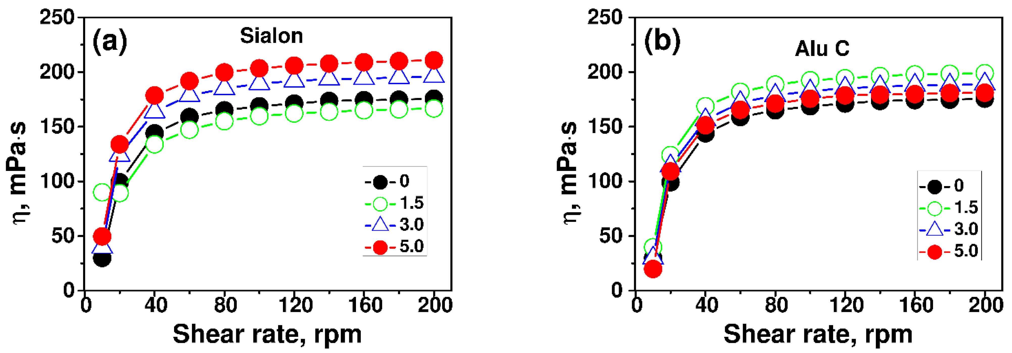
The viscosity of the composition is a very important parameter in the production of varnishes and paints because it determines how they will be applied to the substrate. Therefore, when preparing the composition of new varnishes with Sialon fillers it was necessary to pay particular attention to the type of fillers and the amount of filler added so as to obtain the adequate viscosity of the composition. The viscosity of the composition is also of key importance to the course of polymerization. Resin CN 3755 is characterised by very high viscosity (1400 mPa·s), so it was necessary to add the HDDA reactive diluent (5 mPa·s). This also resulted in a thinner layer of varnish. The Sialon and Alu C were added at a ratio of 0%, 3%, and 5% in relation to the weight of the monomer mixture. Viscosity determines the adequate rate of diffusion processes. Therefore, the individual stages of polymerization depend on viscosity to a greater or lesser extent.
The viscosity of a monomer/inorganic composition strongly depends on the temperature, type, and amount of fillers that have been added and it may also depend on the shear rate. The viscosities of the compositions are shown in Figure 3a the CN 3755/HDDA/Sialon composition (at 25 °C) and Figure 3b the CN 3755/HDDA/Alu C composition (at 25 °C).
The 1.5 wt.% of the Sialon filler added to the varnishes (Figure 3a) slightly reduced the viscosity of the composition. When larger amounts of Sialon (3 wt.% and 5 wt.%) were added, the viscosity of the composition increased by 11% and 20% (at 25 °C), respectively, compared to the viscosity of the compositions without the filler. As far as the varnish compositions containing the Alu C filler are concerned (Figure 3b), the highest increase in viscosity was observed when 1.5 wt.% of the filler was added. When larger amounts of the filler were added, the viscosity decreased slightly. The viscosity of the composition decreased after adding the Alu C because it weakened interactions between the resin molecules. The best interactions between the filler and monomer were observed in the composition containing 1.5 wt.% of Alu C and 5 wt.% of Sialon.
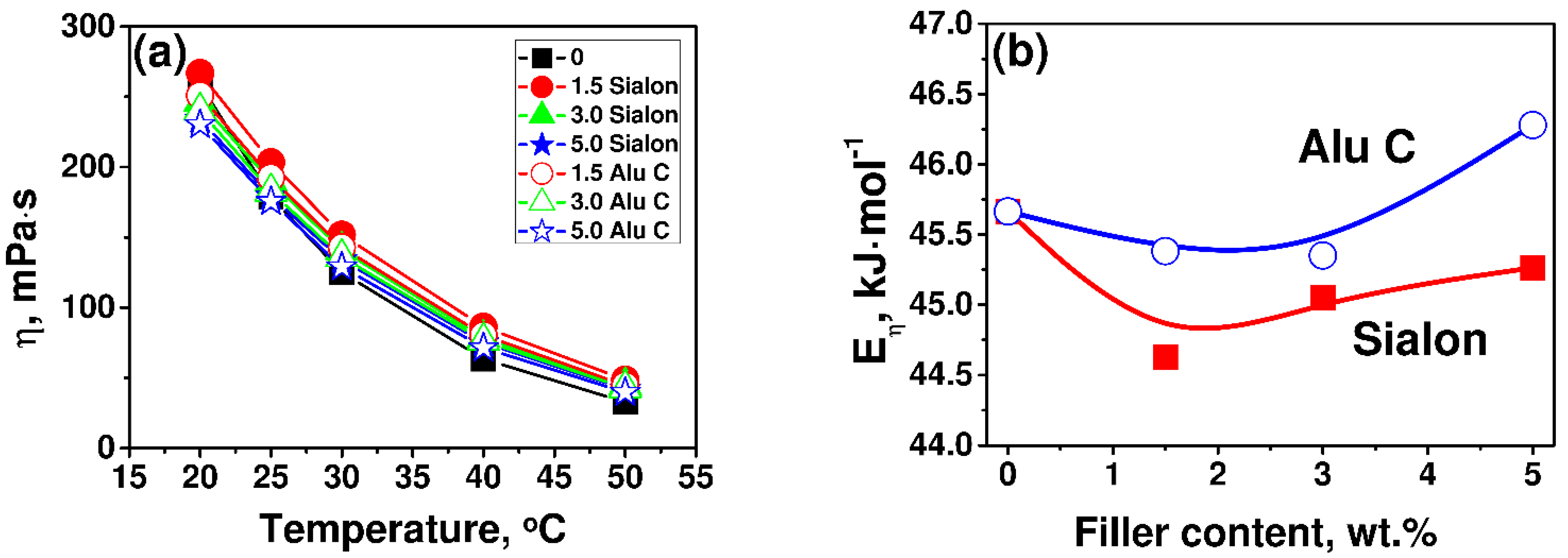
Figure 4a shows a comparison of the dependency between the viscosity of all of the varnish compositions and the temperature at a cone rotational speed of 100 rpm. Figure 4b shows the dependency between the viscosity activation energy Eƞ as the function of the Sialon and Alu C content. As the shear rate increased within the range of its small values, the viscosity also increased. Varnish dispersions are thickened by shearing. This phenomenon can be explained by the formation of particle clusters that increase the effective volume fraction of the filler in the suspension. The rheological behaviour of the Sialon and Alu C dispersions could be associated with its most simple mechanism, i.e., the increase in the system volume. This means that the larger particles of the powder are, the more feasible the dilatancy effect is. This was observed when the microsilica were dispersed in a mixture of mono- and diacrylate [31].
The shear thickening mechanism can be explained by the fact that at rest, the filler particles in the coating composition are highly packed. At low shear rates, the frictional forces between the particles are low because the liquid between them acts as a “lubricant”. As the shear rate increases, the particles are displaced, which results in an increase in the distance between the particles and causes an increase in the grain space. The fluid is therefore unable to fill the increased inter-grain space. The lubricating properties of the fluid are therefore reduced. The friction between the particles increases, and hence, the viscosity of the system increases. The shear thickening phenomenon can be explained as expansion of the system volume, and it thus occurs through the dilatation phenomenon.
An increase in the temperature reduced the viscosity of the composition (Figure 4a) due to the reduction of intermolecular interactions. In this case, these were mainly hydrogen bonds. The activation energy of the monomer mixture was 45.6 kJ/mol (Figure 4b). When 1.5 wt.% of Alu C was added to the monomer mixture, the activation energy Eƞ of the composition was slightly reduced. On the other hand, when a 1.5 wt.% of Sialon was added, the activation energy was significantly reduced due to the disruption of the hydrogen bond network in the mixture. When the filler content increased, the activation energy did as well. This points to the greater influence of the interactions that take place in the fillers (especially in Alu C) and between the monomer and fillers. We can suppose that the varnish compositions containing Alu C have better properties because they reduced the potential barrier that molecules have to overcome when they are in a high-viscosity liquid.
3.2. Scratch Hardness Test
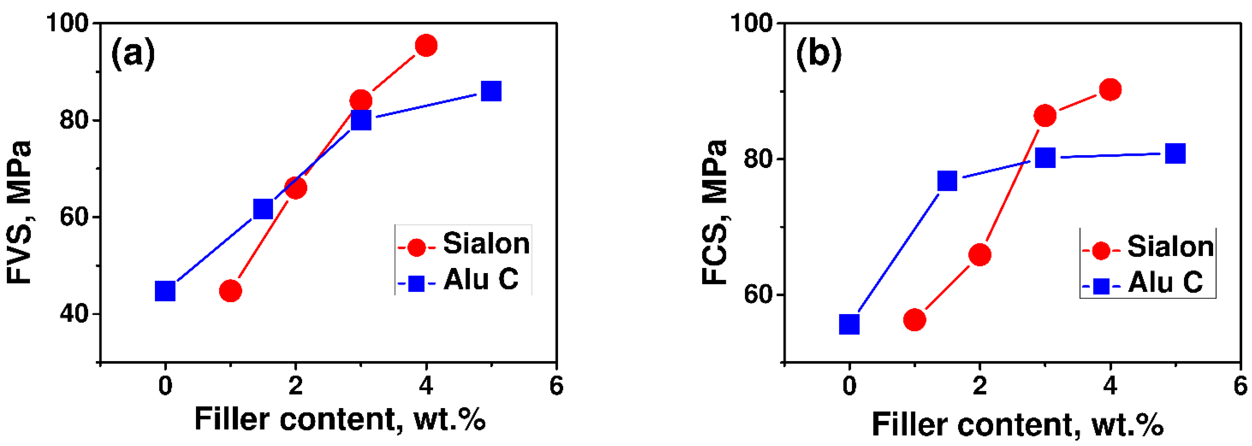
When the varnishes were cured on the MDF substrate, transparent coatings were formed. They were characterised in terms of their surface properties (water contact angle) and mechanical properties (scratch hardness). Scratch hardness is a significant parameter that characterises coatings. It was calculated according to Formula (2), the value of the applied force (load), causing the first visible scratch (FVS) on the coating surface and the scratch width. Using a stereoscopic microscope coupled with computer software, we were able to read the width of the scratches once the varnish was scratched and the coating was stripped off the substrate for the first time. The scratch hardness of the filler-modified coatings was also calculated for the first coating stripping. This was possible due to the larger weight, which allowed us to perform tests up to 40.5 N. The results of the scratch hardness test are presented graphically in Figure 5. Compared to the unmodified system CN 3755/HDDA (FVS = 45.0 MPa, SS = 55 MPa), the presence of fillers in the coatings increased the scratch hardness both in the FVS and SS. The highest scratch hardness for the FVS (about 95 MPa) was observed in the sample modified with 5 wt.% of Sialon. Compared to the initial system, the scratch hardness of this sample increased by as much as 215%. Alu C also resulted in a satisfactory increase in the scratch hardness. The results of the scratch hardness tests showed that even small amounts of fillers (about 3–5 wt.%) modified the properties considerably. At higher concentrations, the changes were less significant (especially for the hardness at the first coating stripping). The varnishes that were based on Sialon were more resistant to scratching and stripping than the coatings containing Alu C (except the varnish containing 1.5 wt.% of Sialon).
3.3. Contact Angle Test
The hydrophilic or hydrophobic characteristic of the material’s surface can be evaluated by measuring the water contact angle ƟW. In our study, we were able to evaluate the changes in the hydrophobicity of the filler-modified varnish coatings using this parameter. The resulting data are particularly important, as they provide the necessary information to help us determine the usefulness of the varnishes.
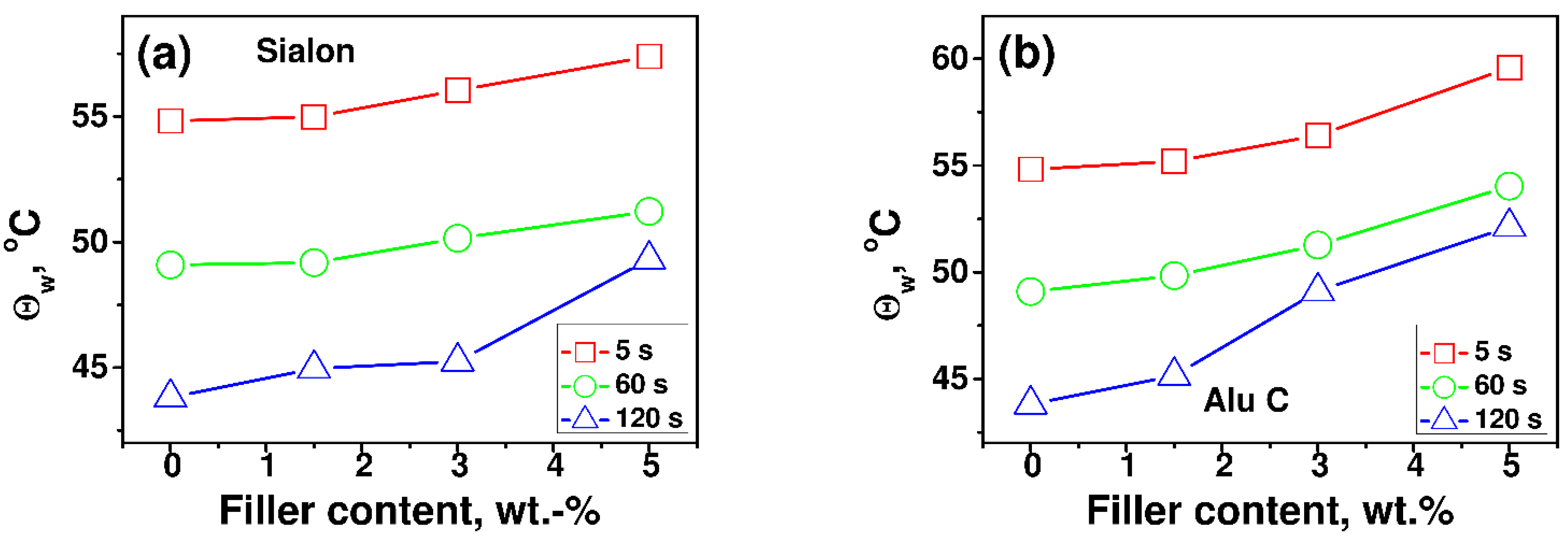
All of the systems based on the MDF substrate underwent the contact angle test. The coating was tested two weeks after it had been applied. Variation in the contact angle was monitored for 2.5 min. The values of the changes that occurred in the contact angle were read 5, 60, and 120 s after the drop had contacted the substrate. The resulting data were used in the diagram showing the dependency between the contact angle and filler content: 1.5, 3 and 5 wt.% in Figure 6 and on the photographs of water drops in Figure 7.
As can be seen (Figure 6 and Figure 7), when the filler was added, the hydrophobic surface properties of the coatings are slightly improved. After 5 s, the value of the contact angle in the initial system was about 54°. This means that the initial coating had hydrophilic properties and was being well wetted with demineralised water. The greatest increase in the contact angle (about 11%) was observed in the composites containing 5 wt.% Alu C. We can suppose that larger amounts of the filler would increase the contact angle value. The differences of the values of contact angles, which were obtained 60 and 120 s after the drop had made contact with the substrate, were able to be attributed to the evaporation and the effect of gravitational and evaporative forces. As shown in Figure 9, the surface of coatings containing inorganic fillers are characterized by a higher Young’s modulus. Lopes and Bonaccurso in [32] show that water drops on soft surfaces evaporate faster than those on hard surfaces, hence the differences in evaporation between samples containing Sialon and Alu C and the unfilled varnish coating.
3.4. Solvent-Resistance Test of Varnish Coatings
The resistance of the varnish coatings to solvents was tested to determine the stability of the products exposed to chemical reagents. The resistance of all of the varnish coatings to selected solvents was tested. When the swabs were removed, the coatings were visually inspected. During the analysis, the following features of the varnish surfaces were taken into account: matting or gloss increased and trace of the drop edge. The occurrence of a phenomenon such as increased gloss or matting of surfaces was marked as “+”, whereas an absence of changes in surface properties was marked as “−“. Additional markings describing the intensity of the drop edge trace (3 > 2 > 1) and the degree of surface matting (♦♦♦ > ♦♦ > ♦ > 0) enabled a more accurate assessment of changes occurring on the surface. The observations are listed in Table 1.
The analysis of the results allows us to conclude that the varnishes made from CN 3755 resins and adequate fillers exhibited significant resistance to various solvents. The properties of all of the samples changed after contact with a 5% sodium hydroxide solution and a 3% sulphuric acid (VI) H2SO4 solution. The solvents caused a medium matting of the surface of varnishes containing the Sialon filler. The amount of the filler had no effect on the matting intensity. The observation of the traces left by the drop edges showed that the area of damage caused by the solvents to the coatings containing Alu C was smaller, and it did not change when the filler content in the coating increased. There were no surface changes resulting from the contact of the varnishes with ethanol, toluene, or acetone.
The analysis of the data in Table 1, which refer to the varnish coatings with different filler contents and types showed that the varnishes containing Alu C were more resistant to various solvents than the products containing Sialon.
3.5. Microscopy Data and Analysis
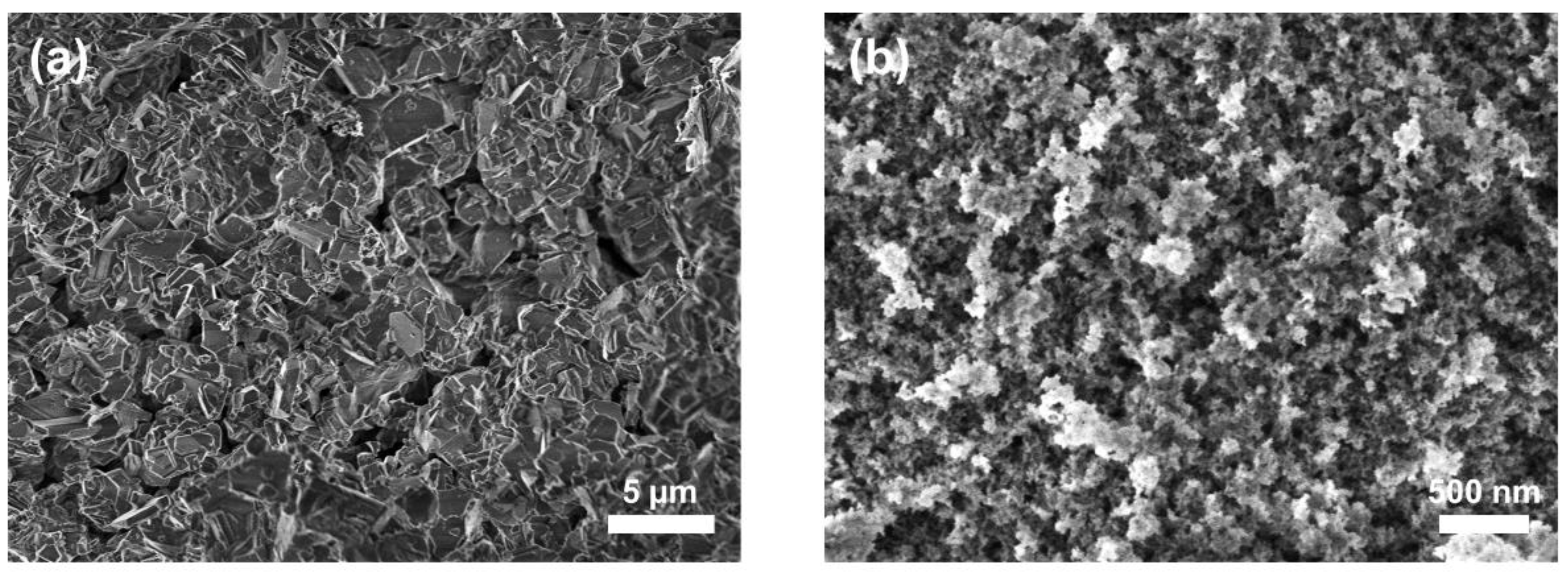
On the one hand, the Sialon sample showed an unregularly shaped particle morphology, with the particles displaying sharp edges (structural anisotropic) (Figure 8a). The size of the particle ranged from submicron to several microns in size. On the other hand, the Alu C shows a morphology comprising nano-sized rounded particles (Figure 8b). Both types of the filler can be thoroughly incorporated in the studied matrix (see Figure 9).
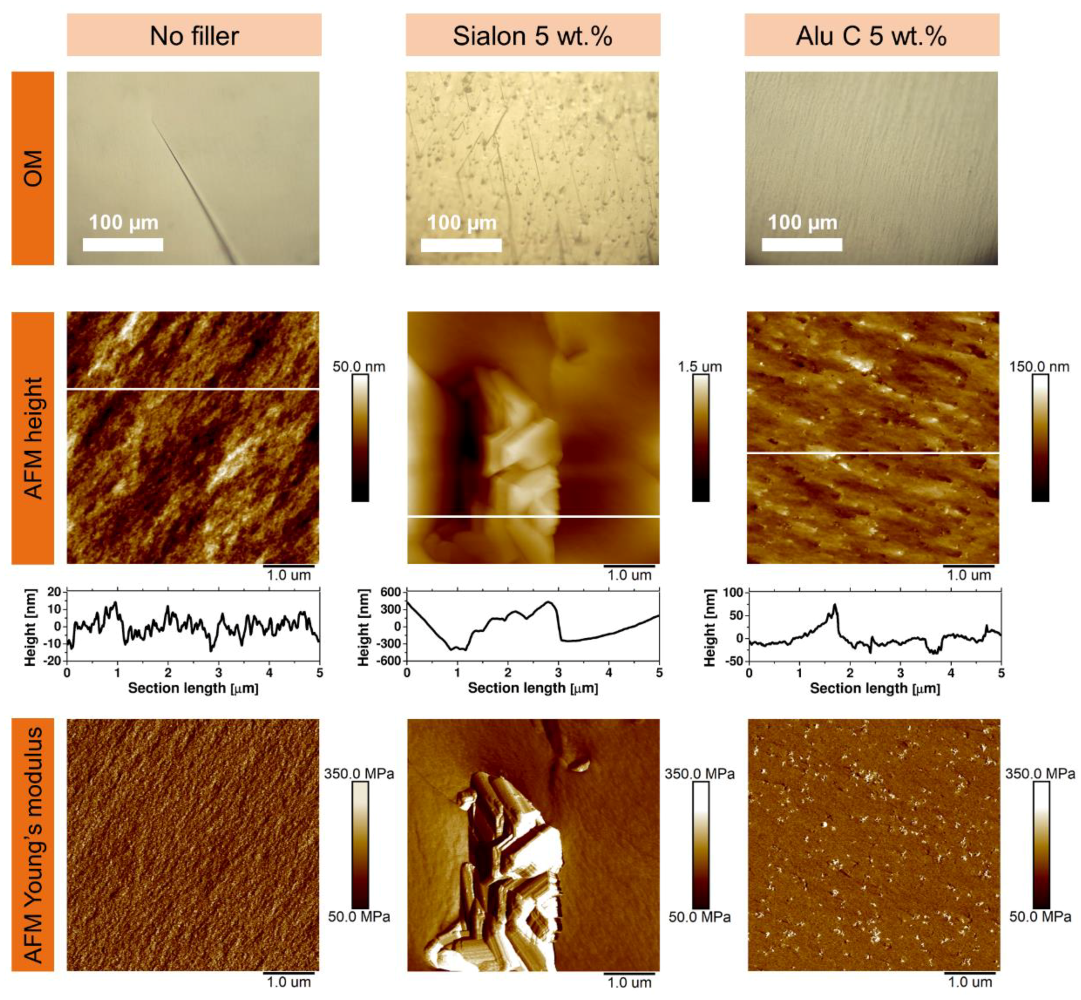
The fractured composition of the unfilled copolymer unveils a flat and homogeneous surface, as shown in optical microscopy images (Figure 9). A line that is visible in the OM image represents a crack propagation line (fractural direction). A 5 × 5 μm2 scan size AFM topography can also be seen; cross-section analysis indicates that the amplitude of the surface profile is only around 30 nm (calculated root mean square surface roughness is 6.9 nm). Concerning the same area, the average value of AFM Young’s modulus was calculated to be 153 MPa.
For the filled matrix, as evidenced by the OM and AFM, both fillers are well distributed in the matrix. Optical microscopy images show many parallel crack propagation lines started/terminated at the Sialon aggregates. A small Sialon aggregate is visible in the AFM height image. The particle contours are coequal to these shown in the SEM images (raw particles, Figure 8). The Alu C fillers are not visible in the OM image; however, a multitude of parallel crack propagation line coincide with their presence, which is confirmed by the AFM Young’s modus mapping: bright spots are the aggregates of the Alu C filler.
All of the microscopy images show that both types of fillers can be decently dispersed in the studied matrix (limited effect of aggregation), thus improving its mechanical properties, particularly the scratch hardness and resistance, as shown earlier.
4. Conclusions
The properties of commercial polymers can be changed by adding filler particles. These treatments result in the formation of polymer composites. At present, the use of Sialon particles used as additives has been gaining interest. In this study, varnishes made from Sialon and Alu C- modified polyacrylate resins were prepared. They were subjected to photopolymerization on a wood-based substrate (MDF), which resulted in the formation of varnish coatings. The varnish compositions were tested for viscosity, and the coatings were tested for scratch hardness and resistance to solvents. The contact angles were measured 5, 60, and 120 s after the drops made contact with the coating.
The addition of 5 wt.% of Alu C increased the contact angle of the samples based on CN 3755 resin by about 11%. The Al2O3 particles tended to migrate towards the surface, thus increasing its hydrophobicity. The use of fillers increased the hydrophobicity of the varnish coatings. Consequently, products coated with the varnishes can be used for longer, and it is easier to remove impurities from them. The coatings were highly resistant to traditional solvents. Changes were only visible on the surface after a 5% sodium hydroxide solution and 3% sulphuric acid (VI) H2SO4 solution made contact with the surface. The varnishes containing Alu C and Sialon were more resistant to the solvents.
The modification of coatings with Sialon also improved their mechanical properties (scratch hardness, scratch resistance). Compared to the initial system, the scratch hardness of the composite containing 5 wt.% of Sialon increased by as much as 215%. The tests showed that the addition of Sialon and Alu C particles to the varnish systems considerably modified the properties of the coatings. The mechanical and surface properties of the varnishes depend on the type and amount of filler added and on the method by which the coatings are prepared. Both types of the filler are well distributed in the matrix, which was confirmed by SEM, OM, and AFM analysis.
Author Contributions
Conceptualization, M.R.; methodology, M.R.; software, M.R., Ł.G. and H.G.; validation, M.R. and Ł.G.; formal analysis, M.R. and H.G.; investigation, M.R. and H.G.; resources, M.R.; data curation, M.R.; writing—original draft preparation, M.R., H.G. and Ł.G.; writing—review and editing, M.R., H.G. and Ł.G.; visualization, M.R.; supervision, Ł.G.; project administration, M.R.; funding acquisition, Ł.G. All authors have read and agreed to the published version of the manuscript.
Funding
Project of the Poznań University of Technology No. 0611/SBAD/0115 entitled: Design, testing and analysis of parts, assemblies of machines and vehicles for the purpose of searching for innovative solutions: 0611/SBAD/0115.
Institutional Review Board Statement
Not applicable.
Informed Consent Statement
Not applicable.
Data Availability Statement
Not applicable.
Acknowledgments
This work was supported by the Ministry of Science and Higher Education. H.G. acknowledges support within the Bekker Programme from the Polish National Agency for Academic Exchange. Authors acknowledge Clemens Padberg for help during SEM imaging.
Conflicts of Interest
The authors declare no conflict of interest.
References
- Badev, A.; Abouliatim, Y.; Chartier, T.; Lecamp, L.; Lebaudy, P.; Chaput, C.; Delage, C. Photopolymerization kinetics of a polyether acrylate in the presence of ceramic fillers used in stereolithography. J. Photochem. Photobiol. A Chem. 2011, 222, 117–122. [Google Scholar] [CrossRef]
- Kaur, M.; Srivastava, A.K. Photopolymerization. A review. J. Macromol. Sci. Part C Polym. Rev. 2002, 42, 481–512. [Google Scholar] [CrossRef]
- Fouassier, J.P.; Allonas, X.; Burget, D. Photopolymerization reactions under visible lights. Principle, mechanisms and examples of applications. Prog. Org. Coat. 2003, 47, 16–36. [Google Scholar] [CrossRef]
- Ozawa, T.; Ishiwata, S.; Kano, Y.; Kasemura, T. Acrylate copolymer/ultraviolet curable oligomer blends as pressure-sensitive adhesives. J. Adhes. 2000, 72, 1–16. [Google Scholar] [CrossRef]
- Bednarczyk, P.; Mozelewska, K.; Czech, Z. Influence of the UV crosslinking method on the properties of acrylic adhesive. Int. J. Adhes. Adhes. 2020, 102, 102652. [Google Scholar] [CrossRef]
- Bednarczyk, P.; Pawlikowska, M.; Czech, Z. Primers used in UV-curable nail varnishes. Int. J. Adhes. Adhes. 2017, 74, 177–180. [Google Scholar] [CrossRef]
- Lee, S.W.; Park, J.W.; Park, C.H.; Kwon, Y.E.; Kim, H.J.; Kim, E.A.; Woo, H.S.; Schwartz, S.; Rafailovich, M. Optical properties and UV-curing behaviors of optically clear PSA-TiO2 nano-composites. Int. J. Adhes. Adhes. 2013, 44, 200–208. [Google Scholar] [CrossRef]
- Sadej, M.; Andrzejewska, E. Silica/aluminum oxide hybrid as a filler for photocurable composites. Prog. Org. Coat. 2016, 94, 1–8. [Google Scholar] [CrossRef]
- Sadej, M.; Andrzejewska, E.; Kurc, B.; Gojzewski, H.; Jesionowski, T. Surface-dependent effect of functional Silica fillers on photocuring kinetics of hydrogel materials. J. Polym. Sci. Part A Polym. Chem. 2014, 1, 3472–3487. [Google Scholar] [CrossRef]
- Sadej, M.; Gojzewski, H.; Andrzejewska, E. Photocurable polymethacrylate-Silica nanocomposites. Correlation between dispersion stability, curing kinetics, morphology and properties. J. Polym. Res. 2016, 23, 1191. [Google Scholar] [CrossRef] [Green Version]
- Sadej-Bajerlain, M.; Gojzewski, H.; Andrzejewska, E. Monomer/modified nanosilica systems. Photopolymerization kinetics and composite characterization. Polymer 2011, 52, 1495–1503. [Google Scholar] [CrossRef]
- Ziobrowski, P.; Andrzejewska, E.; Szybowicz, M.; Nowicka, A.; Sadej-Bajerlein, M.; Gojzewski, H.; Drozdowski, M. Particle clustering in photocurable nanocomposites. Dependence of curing kinetics and viscoelastic properties. J. Appl. Polym. Sci. 2014, 131, 39895. [Google Scholar] [CrossRef]
- Balcerak, A.; Kwiatkowska, D.; Iwińska, K.; Kabatc, J. Highly efficient UV-Vis light activated three-component photoinitiators composed of tris(trimethylsilyl)silane for polymerization of acrylates. Polym. Chem. 2020, 11, 5500–5511. [Google Scholar] [CrossRef]
- Cui, R.; Wang, K.; Ma, G.; Qian, B.; Yang, J.; Yu, Q.; Nie, J. Photopolymerization characteristics of bisbenzo[1,3]dioxol-5-ylmethanone as an initiator. J. Appl. Polym. Sci. 2011, 120, 2754–2759. [Google Scholar] [CrossRef]
- Dietlin, C.; Schweizer, S.; Xiao, P.; Zhang, J.; Morlet-Savary, F.; Graff, B.; Fouassier, J.-P.; Lalevée, J. Photopolymerization upon LEDs: New photoinitiating systems and strategies. Polym. Chem. 2015, 6, 3895–3912. [Google Scholar] [CrossRef]
- Fang, B.; Jin, M.; Wu, X.; Zhang, Y.; Wan, D. Near UV-vis LED-excitable two-branched sensitizers for cationic, radical, and thiol-ene photopolymerizations. Dye. Pigment. 2016, 126, 54–61. [Google Scholar] [CrossRef]
- Andrzejewska, E. Photopolymerization kinetics of multifunctional monomers. Prog. Polym. Sci. 2001, 26, 605–665. [Google Scholar] [CrossRef]
- Mayer, P.; Dmitruk, A.; Jóskiewicz, M.; Głuch, M. Pull-off strength of fiber-reinforced composite polymer coatings on aluminum substrate. J. Adhes. 2020, 97, 1371–1387. [Google Scholar] [CrossRef]
- Bednarczyk, P.; Mozelewska, K.; Nowak, M.; Czech, Z. Photocurable Epoxy Acrylate Coatings Preparation by Dual Cationic and Radical Photocrosslinking. Materials 2021, 14, 4150. [Google Scholar] [CrossRef] [PubMed]
- Crivello, J.V.; Reichmanis, E. Photopolymer materials and processes for advanced technologies. Chem. Mater. 2014, 26, 533–548. [Google Scholar] [CrossRef]
- Lämmlein, S.L.; Mannes, D.; van Damme, B.; Burgert, I.; Schwarze, F.W.M. Influence of varnishing on the vibro-mechanical properties of wood used for violins. J. Mater. Sci. 2019, 54, 8063–8095. [Google Scholar] [CrossRef]
- Sun, Z.; Liu, B.; Huang, S.; Wu, J.; Zhang, Q. Facile fabrication of superhydrophobic coating based on polysiloxane emulsion. Prog. Org. Coat. 2017, 102, 131–137. [Google Scholar] [CrossRef]
- Tan, H.; Yang, D.; Xiao, M.; Han, J.; Nie, J. Preparation of Silica /polyurethane nanocomposites by uv-induced polymerization from surfaces of Sialon. J. Appl. Polym. Sci. 2009, 111, 1936–1941. [Google Scholar] [CrossRef]
- Ivanov, Y.; Cheshkov, V.; Natova, M. Polymer Composite Materials—Interface Phenomena & Processes; Springer Science & Business Media: New York, NY, USA, 2001; Volume 90, p. 184. [Google Scholar]
- Adeniyi, A.S.; Ahmed, B.A.; Hakeem, A.S.; Patel, F.; Bakare, A.I.; Ul-Hamid, A.; Khan, A.A.; Ehsan, M.A.; Khan, T.I. The property characterization of α-Sialon/Ni composites synthesized by spark plasma sintering. Nanomaterials 2019, 9, 1682. [Google Scholar] [CrossRef] [Green Version]
- Cinausero, N.; Azema, N.; Cochez, M.; Ferriol, M.; Essahli, M.; Ganachaud, F.; Lopez-Cuesta, J.M. Influence of the surface modification of alumina nanoparticles on the thermal stability and fire reaction of PMMA composites. Polym. Adv. Technol. 2008, 19, 701–709. [Google Scholar] [CrossRef]
- Jouyandeh, M.; Yarahmadi, E.; Didehban, K.; Ghiyasi, S.; Paran, S.M.R.P.; Puglia, D.; Ali, J.A.; Jannesari, A.; Saeb, M.R.; Ranjbar, Z.; et al. Cure kinetics of epoxy/graphene oxide (GO) nanocomposites: Effect of starch functionalization of GO nanosheets. Prog. Org. Coat. 2019, 136, 105217. [Google Scholar] [CrossRef]
- Marcinkowska, A.; Prządka, D.; Andrzejewska, E. POSS functionalized with mixed fluoroalkyl and methacryloxy substituents as modifiers for UV-curable coatings. J. Coat. Technol. Res. 2019, 16, 167–178. [Google Scholar] [CrossRef] [Green Version]
- Hutter, J.L.; Bechhoefer, J. Calibration of atomic-force microscope tips. Rev. Sci. Instrum. 1993, 64, 1868–1873. [Google Scholar] [CrossRef] [Green Version]
- Derjaguin, B.V.; Muller, V.M.; Toporov, Y.P. Effect of contact deformations on the adhesion of particles. J. Colloid Interface Sci. 1975, 53, 314–326. [Google Scholar] [CrossRef]
- Woźniak, M.; Hazan, Y.; Graule, T.; Kata, D.J. Rheology of UV curable colloidal silica dispersions for rapid prototyping applications. J. Eur. Ceram. Soc. 2009, 29, 2259–2265. [Google Scholar] [CrossRef]
- Lopes, M.C.; Bonaccurso, E. Evaporation control of sessile water drops by soft viscoelastic surfaces. Soft Matter 2012, 8, 7875–7881. [Google Scholar] [CrossRef]
Figure 1.
Schematics of coating of substrate: (a) preparing MDF boards for lacquering, (b) performance of coatings.
Figure 1.
Schematics of coating of substrate: (a) preparing MDF boards for lacquering, (b) performance of coatings.

Figure 2.
Photograph of unfilled varnish coatings and varnish coatings containing: 5 wt.% Alu C and 5 wt.% Sialon (from left to right).
Figure 2.
Photograph of unfilled varnish coatings and varnish coatings containing: 5 wt.% Alu C and 5 wt.% Sialon (from left to right).

Figure 3.
The viscosity of the formulation as the function of the shear rate and the filler content at 25 °C; (a) Sialon, (b) Alu C. The numbers indicate the filler content as weight percent. The lines are guides to the eye.
Figure 3.
The viscosity of the formulation as the function of the shear rate and the filler content at 25 °C; (a) Sialon, (b) Alu C. The numbers indicate the filler content as weight percent. The lines are guides to the eye.

Figure 4.
The (a) viscosity of the formulation at a shear rate ~100 rpm as the function of the temperature and (b) the dependency between the viscosity activation energy Eƞ as the Sialon and Alu C content function. The numbers indicate the filler content as weight percent. The lines are guides for the eye.

Figure 5.
Scratch hardness for: (a) the first visible scratch (FVS) and (b) the first coating stripping (FCS) as a function of the Sialon and Alu C content in the coatings.
Figure 5.
Scratch hardness for: (a) the first visible scratch (FVS) and (b) the first coating stripping (FCS) as a function of the Sialon and Alu C content in the coatings.

Figure 6.
Surface contact angle ƟW as the: (a) Sialon and (b) Alu C content function in the coatings.
Figure 6.
Surface contact angle ƟW as the: (a) Sialon and (b) Alu C content function in the coatings.

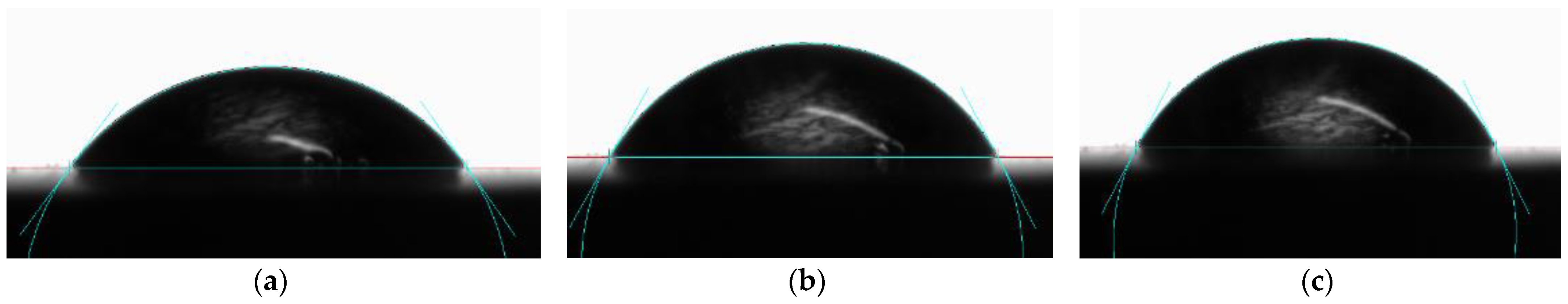
Figure 7.
The image of water drops, captured during the contact angle ƟW measurements after 5 s from the deposition beginning for the coatings containing: (a) no fillers; (b) 5 wt.% Sialon; and (c) 5 wt.% Alu C.
Figure 7.
The image of water drops, captured during the contact angle ƟW measurements after 5 s from the deposition beginning for the coatings containing: (a) no fillers; (b) 5 wt.% Sialon; and (c) 5 wt.% Alu C.

Figure 8.
SEM micrographs of (a) Sialon and (b) Alu C fillers.

Figure 9.
Cumulative OM and AFM images of the bulk surfaces (fractured specimens): unfilled, filled with Sialon 5 wt.% and filled with Alu C 5 wt.% particles. White lines in the height images are profiles of the cross-section analysis shown under them.
Figure 9.
Cumulative OM and AFM images of the bulk surfaces (fractured specimens): unfilled, filled with Sialon 5 wt.% and filled with Alu C 5 wt.% particles. White lines in the height images are profiles of the cross-section analysis shown under them.


Table 1.
The results of the test for the resistance of varnish coatings to solvents.
| Sialon (wt.%) | Alu C (wt.%) | |||||||
|---|---|---|---|---|---|---|---|---|
| 0.0 | 1.5 | 3.0 | 5.0 | 1.5 | 3.0 | 5.0 | ||
| NaOH | Surface matting | + 2 | + 2 | + 2 | + 2 | + 2 | + 2 | + 2 |
| Gloss increase | − | − | − | − | − | − | − | |
| Drop edge trace | + ♦♦ | + ♦♦ | + ♦♦ | + ♦♦ | + ♦♦ | + ♦♦ | + ♦♦ | |
| H2SO4 | Surface matting | − | − | − | − | − | − | − |
| Gloss increase | − | − | − | − | − | − | − | |
| Drop edge trace | + ♦♦ | + ♦♦ | + ♦♦ | + ♦♦ | + ♦ | + ♦ | + ♦ | |
“+”, the occurrence of a phenomenon; “−” no occurrence of a phenomenon. Drop edge trace intensity (3—high; 2—medium; 1—low). Degree of matting (♦♦♦—high; ♦♦—medium; ♦—low; 0—none).
Publisher’s Note: MDPI stays neutral with regard to jurisdictional claims in published maps and institutional affiliations. |
© 2021 by the authors. Licensee MDPI, Basel, Switzerland. This article is an open access article distributed under the terms and conditions of the Creative Commons Attribution (CC BY) license (https://creativecommons.org/licenses/by/4.0/).
Share and Cite
MDPI and ACS Style
Robakowska, M.; Gierz, Ł.; Gojzewski, H. Sialon and Alumina Modified UV-Curable Coatings with Improved Mechanical Properties and Hydrophobicity. Coatings 2021, 11, 1424. https://doi.org/10.3390/coatings11111424
AMA Style
Robakowska M, Gierz Ł, Gojzewski H. Sialon and Alumina Modified UV-Curable Coatings with Improved Mechanical Properties and Hydrophobicity. Coatings. 2021; 11(11):1424. https://doi.org/10.3390/coatings11111424
Chicago/Turabian StyleRobakowska, Mariola, Łukasz Gierz, and Hubert Gojzewski. 2021. "Sialon and Alumina Modified UV-Curable Coatings with Improved Mechanical Properties and Hydrophobicity" Coatings 11, no. 11: 1424. https://doi.org/10.3390/coatings11111424
Note that from the first issue of 2016, this journal uses article numbers instead of page numbers. See further details here.