Article

Electroplating of Pure Aluminum from [HMIm][TFSI]–AlCl3 Room-Temperature Ionic Liquid

1
Department of Materials Science and Engineering, Tel-Aviv University, Tel Aviv 6997801, Israel
2
Department of Materials Engineering, Ben-Gurion University of the Negev, P.O. Box 653, Beer Sheva 8410501, Israel
*
Author to whom correspondence should be addressed.
Coatings 2021, 11(11), 1414; https://doi.org/10.3390/coatings11111414
Submission received: 20 September 2021 / Revised: 16 November 2021 / Accepted: 18 November 2021 / Published: 19 November 2021
(This article belongs to the Special Issue Recent Developments of Electrodeposition Coatings II)

Abstract

:
Electrodeposition of aluminum and its alloys is of great interest in the aerospace, automobile, microelectronics, energy, recycle, and other industrial sectors, as well as for defense and, potentially, electrochemical printing applications. Here, for the first time, we report room-temperature electroplating of pure aluminum on copper and nickel substrates from an ionic liquid (IL) consisting of 1-Hexyl-3-methylimidazolium (HMIm) cation and bis(trifluoromethylsulfonyl)imide (TFSI) anion, with a high concentration of 8 mol/L AlCl3 aluminum precursor. The aluminum deposits are shown to have a homogeneous and dense nanocrystalline structure. A quasi-reversible reaction is monitored, where the current is affected by both charge transfer and mass transport. The electrocrystallization of Al on Ni is characterized by instantaneous nucleation. The deposited Al layers are dense, homogeneous, and of good surface coverage. They have a nanocrystalline, single-phase Al (FCC) structure, with a dislocation density typical of Al metal. An increase in the applied cathodic potential from −1.3 to −1.5 V vs. Pt resulted in more than one order of magnitude increase in the deposition rate (to ca. 44 μm per hour), as well as in ca. one order of magnitude finer grain size. The deposition rate is in accordance with typical industrial coating systems.

1. Introduction

Being one of the abundant elements in the Earth crust, and with extensive uses in modern industry, the aluminum’s global production has risen over 50% in the last decade [1]. With the growth of demand [2] grows the need of finding alternative manufacturing processes for aluminum that will lower the carbon footprint and high environmental impact [3]. Electrodeposition of aluminum and its alloys is of great interest for different applications and industries, and of higher energy efficiency compared to mostly used technologies [4]. Aluminum coatings are potential eco-friendly alternatives to cadmium coatings [4]. With recent advances in 3D meniscus-confined electrodeposition (MCED) [5], 2D patterning, deposition, and repair of aluminum-based structures may become possible. This is of great interest because high-quality 3D-printed aluminum is hard to obtain via conventional powder or laser additive manufacturing processes, such as powder bed fusion and directed energy deposition [6,7], and since the high resolution attainable by MCED is not achievable by most other manufacturing processes.
Aluminum cannot be deposited from aqueous solutions (or other protic solvents) due to its very negative reduction potential (E0 = −1.662 V vs. SHE [8]), which falls well below the hydrogen evolution line in the Pourbaix diagram [8]. Consequently, the Faradaic efficiency for deposition of aluminum from aqueous solutions is essentially zero [9], and the necessary energy makes the process impractical [8]. These limitations can be overcome by electroplating aluminum from non-aqueous solvents, namely, eutectic formulations, molten salts, or ionic liquids (ILs) [10,11,12]. Such non-aqueous solutions have attracted much interest because they are often non-volatile, non-flammable, and environmentally friendly. They also have very low vapor pressures, and exhibit high solubility, high stability, and a wide electrochemical window [10,13]. However, the so-obtained coatings have suffered from poor quality, inhomogeneity, poor adhesion, and low throwing power [10]. ILs are typically aprotic; thus, hydrogen ion-related problems can be avoided [13]. ILs are (mainly organic) salts that melt at temperatures below 100 °C and have extremely low or negative vapor pressure [14]. ILs comprise of cations and anions [15]. When selecting an IL for electrodeposition, one should first consider its physical properties, such as air and water stability, deposition temperature, viscosity, electrical conductivity, potential window, solubility of metal salts, environmental hazards, etc. [16].
Over the years, many studies have been dedicated to electroplating of aluminum from ILs, with great interest in room-temperature ILs (RTILs). The ILs formed by mixing aluminum chloride (AlCl3) with 1-ethyl-3-methylimidazolium chloride ([EMIm]Cl) have been considered as promising for electroplating aluminum [4,17]. Nanocrystalline aluminum has been obtained from both [EMIm]Cl–AlCl3 and 1-ethyl-3-methylimidazolium bis(trifluoromethylsulfonyl)amide [EMIm]Tf2N–AlCl3 additive-free RTILs [18]. Aluminum was even electrodeposited outside the glovebox from a [EMIm]Cl–AlCl3 IL using a non-water absorbable layer [19]. While the crystal size was reduced to the nanometer scale when using a [EMIm][TFSI]-based IL, the concentration of AlCl3 was also lower compared to that of [EMIm]Cl–AlCl3 IL. Bund et al. [20,21,22,23] also studied the electrodeposition and dissolution of aluminum from [EMIm]Cl-based ILs.
Bis(trifluoromethylsulfonyl)imide (TFSI) anion-based ILs have been reported to exhibit wide electrochemical window, high conductivity, low viscosity, high thermal stability, and hydrophobicity [24,25,26,27]. The TFSI has a strong delocalized charge, making it harder for H-bonds to form, thus lowering the interaction with water molecules and reducing ion interaction in the IL [28].
The 1-Hexyl-3-methylimidazolium (HMIm) cation belongs to the family of imidazolium cations, which are known to have promising properties, including high solid-state conductivity and large electrochemical window [29]. Its relatively long hexyl side chain increases its overall size, which, in turn, causes the growth of non-polar domains and allows higher solubility of non-polar species [15]. Compared to [EMIm] and 1-Butyl-3-methylimidazolium (BMIm), [HMIm], with its larger alkyl chain length, has higher viscosity, lower miscibility in water, and a lower melting point [30]. The commercially available [HMIm][TFSI] IL used in this work is characterized by stability, low viscosity, low water solubility, ease of preparation and purification, and water content as low as 20 ppm (due to its hydrophobicity) [31].
Here, we report room-temperature electroplating of pure nanocrystalline aluminum on copper and nickel substrates from an [HMIm][TFSI]–AlCl3 IL. The high solubility of the aluminum salt in this IL allowed the use of a high concentration of 8 mol/L AlCl3 in [HMIm][TFSI] IL. While the physical properties and some potential applications of [HMIm][TFSI] IL have been reported before [29,32,33,34], to the best of our knowledge, this is the first report of its use in the electroplating of aluminum.

2. Materials and Methods

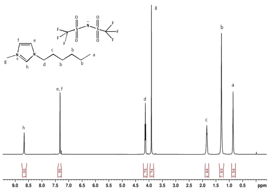
2.1. Preparation of the IL

Before use, anhydrous aluminum chloride (>99.985%, CAS No. 7446-70-0, product No. 88488, Lot No. W26E011, Alfa Aesar, Lancashire, UK) and 1-hexyl-3-methylimidazolium bis(trifluoromethyl sulfonyl)imide [HMIm][TFSI] (>98%, CAS No. 382150-50-7, Lot No. BCBZ9535, Sigma-Aldrich, Taufkirchen, Germany) were dried at 80 °C for 12 h in a small vacuum oven for gloveboxes (TCH-005, VST, Petach Tikva, Israel). The oven was installed inside a nitrogen-filled glovebox with less than one ppm oxygen/water (LabMaster130, MBroun, Garching, Germany). After drying, the reagents were sealed and kept at room temperature inside the glovebox until use.
While in the glovebox, the [HMIm][TFSI]–AlCl3 RTIL with 8 mol/L AlCl3 was prepared by heating [HMIm][TFSI] at 80 °C in a beaker on top of a hot plate and slowly adding AlCl3 while continuously stirring on a magnetic stirrer. Light white smoke was noticed during preparation [17], although no temperature change was monitored, and the solution changed its color from colorless to yellowish. The solution was mixed continuously for 2 h until the aluminum salt was completely dissolved. Subsequently, stirring was stopped, and the solution was separated into two phases: a top phase with a light-yellow color and lower viscosity, and a bottom, transparent phase. The IL was then cooled down to room temperature. The solution was kept in the glovebox for a week until the lower phase solidified. The upper phase was then ready for use for electroplating.

2.2. Electroplating and Electrochemical Experiments

All electrochemical experiments were carried out in a three-electrode cell containing 5 cm3 IL at room temperature (~23.5 °C) and using a potentiostat–galvanostat (PGSTAT12, Metrohm Autolab B.V., Utrecht, The Netherlands). Conducting the experiments in a glovebox helped to avoid the use of a protection layer, such as decane [35], in order to avoid contamination. The working electrode (WE) was initially a Cu disk, to which good adhesion of the Al coating was observed. However, when Cu dissolution in the IL solution was noticed during cyclic voltammetry (CV) experiments, it was decided to switch to a pure Ni (99.99%) disk. The latter remained immune in the IL solution, the tradeoff being lower deposition currents and not as good adhesion of the coating to the substrate. However, the adhesion was improved following surface activation of the Ni substrate via mechanical grinding. The rods, which were 3 mm in diameter, were ground on SiC papers down to 4000 grit to obtain a uniform, fresh surface. High-purity Al foil (99.997%, Alfa Aesar, Ward Hill, MA, USA) served as a counter electrode (CE) to maintain a constant source of Al ions in the solution, while a Pt wire (99.997%, Johnson Matthey, Royston, England) served as a quasi/pseudo reference electrode (QRE). Both the CE and the QRE were chemically polished in an acidic solution that consisted of 2:1 (vol.) HCl:H2O2. Subsequently, they were rinsed with deionized (DI) water and dried with kimtech tissue. The CE was also ground mechanically inside the glovebox before each daily set of experiments, in order to remove oxide from the surface. All electrodes were stored in the glovebox.
The use of QREs is a common practice in electrochemical studies in ILs. These QREs are most often Ag or Pt wires immersed directly in the IL [36,37,38,39], although Al wires are also quite common [20,21,22,23]. Hereafter, all potential values will be expressed versus a Pt wire QRE. Preliminary measurements in a two-electrode cell comprised of a Pt wire and a Ni substrate showed that 20 min were required to reach a steady state (at E = −0.780 ± 0.001 V). Hence, in all experiments thereafter, the QRE was first submerged in the IL solution for at least 30 min.
CV measurements on a Ni substrate were conducted in order to determine the optimal applied potential for electroplating, the reversibility of the electrochemical cell, and the species most likely to be involved. The open-circuit potential (OCP) was first established at −0.78 V. Next, the potential was scanned in the negative direction from −0.4 V to −1.5 V, and then the scan was reversed back to −0.4 V. The scan rates were between 1 and 50 mV/s. Chronoamperometry experiments were conducted in order to evaluate the electrocrystallization mechanism. The potential of the WE was stepped in the negative direction from an initial value, where no reduction in aluminum would occur, to a cathodic overpotential, where a current transient was observed. Electroplating of Al on Ni for microstructural characterization was conducted for either 20 or 120 min at −1.5, −1.4, and −1.3 V.

2.3. Analytical Characterization

Liquid-state nuclear magnetic resonance (NMR) [40] spectra were acquired in order to verify the identity and purity of the [HMIm][TFSI] reagents purchased from Sigma-Aldrich. To this aim, a Bruker NEO 400 spectrometer with a 9.4-T narrow-bore superconducting magnet was used (1H at 400.13 MHz). All samples were prepared by dissolving a 0.1-mL sample in 0.6 mL of chloroform (CDCl3) solvent and sealed in a 5-mm standard NMR tube in an argon-filled glovebox. All NMR experiments were conducted at ambient temperature. The 1H NMR chemical shift was calibrated to the reference of 1 M tetramethylsilane.
Liquid chromatography mass spectrometry (LC–MS) was used to characterize the anionic and cationic species in the as-received [HMIm][TFSI] reagent, fresh RTIL, and used RTIL. Preliminary tests were run with different ionization techniques: atmospheric solids analysis probe (ASAP), atmospheric pressure chemical ionization (APCI), and atmospheric pressure photoionization (APPI) [41]. Then, electrospray ionization (ESI) high-resolution MS (HRMS) [42] was used. All ESI spectra were acquired using Xevo G2-XS QTof mass spectrometer coupled with ACQUITY I-class UPLC (Waters Corp., Milford, MA, USA). Here, QTof stands for quadrupole time-of-flight, and UPLC stands for ultra-performance LC. The sample was prepared by dilution of a 1-μL RTIL solution with 5 μL of oacetonitrile under nitrogen atmosphere, and was immediately analyzed by ESI in both positive (ES+) and negative (ES−) ion modes. The ES+ mode is useful to detect species with basic sites that can be protonated at a low pH. In contrast, the ES mode is useful to detect species with acidic sites that can be deprotonated. Then, 0.1% formic acid was injected to the analyte solution during the ESI run to enhance protonation and increase sensitivity. Data were analyzed using MassLynx™ software (Waters Corp., Milford, MA, USA).
The chemistry and oxidation states at the surface of the Al coating were determined by X-ray photoelectron spectroscopy (XPS). These measurements were performed in ultrahigh vacuum (UHV, 2.5 × 10⁻¹⁰ Torr base pressure) using a 5600 Multi-Technique System (Physical Electronics, Inc. (PHI), Chanhassen, MN, USA). The sample was irradiated with an Al Kα monochromated source (1486.6 eV), and the outcome electrons were analyzed by a Spherical Capacitor Analyzer using a slit aperture of 0.8 mm. The sample was analyzed after 6 min sputter cleaning with a 4-kV Ar+ ion gun. The first sample was analyzed at the surface and used to set the sputtering time. Sputtering was set to 5.7 min at 4 × 4 mm calibrated to 47.6 nm/min for SiO2/Si. The charge was neutralized. The C 1s adventitious carbon peak with a binding energy (BE) of 284.8 eV was used to correct the BE scale and account for a possible charging effect. First, survey spectra were acquired within a wide energy window (0–1400 eV) in order to identify the elements present on the sample’s surface. Next, utility multiplex spectra were taken for different peaks of all the elements considered for atomic concentration in a low-energy window at an intermediate resolution. Finally, high-resolution multiplex spectra were acquired for different peaks in a pass energy of 11.75 eV at steps of 0.05 eV. These measurements allow precise energy position and peak shape determination, which are necessary for chemical bonding analysis.
The surface morphology and elemental composition of the coating were characterized by scanning electron microscopy (SEM) and energy-dispersive X-ray spectroscopy (EDS). For surface morphology characterization, a Gemini 300 microscope (ZEISS, Oberkochen, Germany) was used, whereas chemical analysis was conducted in a field-emission SEM (model JSM-6700, JEOL, Tokyo, Japan). Transmission electron microscopy (TEM) analysis was performed in a JEOL JEM-2100 microscope (Tokyo, Japan) operating at 200 kV and equipped with a NORAN EDS spectrometer. TEM samples were prepared using Helios Nanolab 460F1Lite dual-beam-focused ion beam (FIB)-SEM (Thermo Fisher Scientific, Waltham, MA, USA). Crystallographic characterization of the coating was performed with selected area electron diffraction (SAED) patterns acquired in the TEM as well as by X-ray diffraction (XRD, D8 ADVANCE diffractometer with a Cu anode, Bruker AXS, Madison, WI, USA).

3. Results

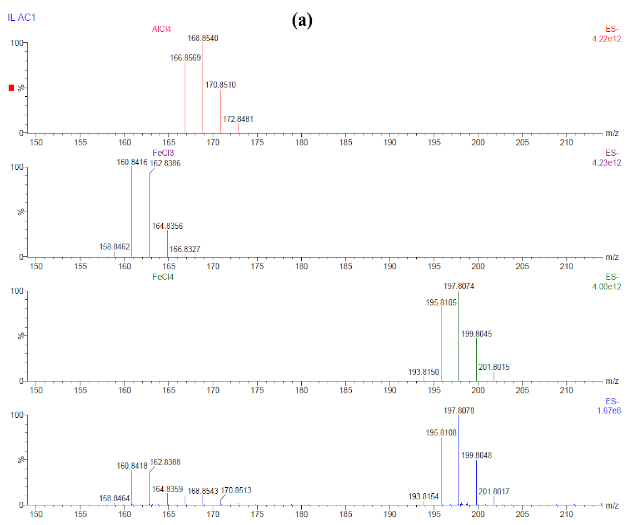
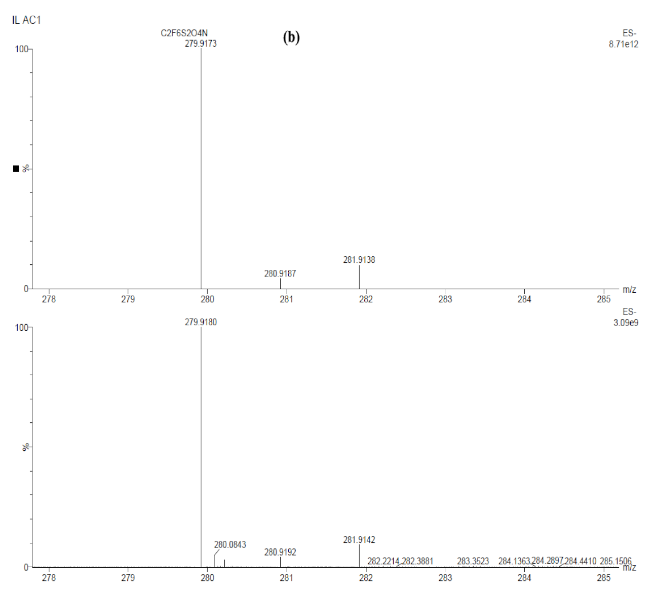
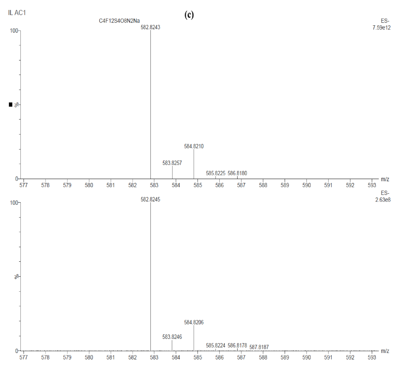
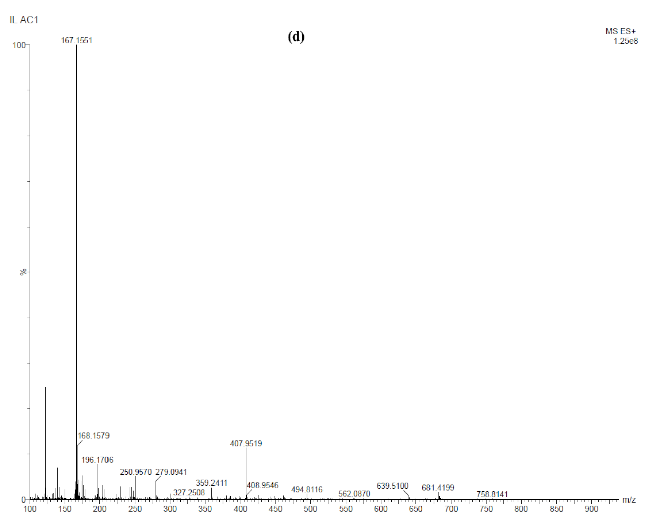
3.1. Ionic Species in [HMIm][TFSI]–AlCl3 IL

Figure 1 shows the NMR 1H spectrum of the as-received [HMIm][TFSI] reagent dissolved in CDCl3. The spectrum matches that of CAS No. 382150-50-7, with no signal of water impurity in CDCl3, as that reported elsewhere [43,44]. Since the TFSI molecule does not contain any protons, only peaks of HMIm are evident in the 1H spectrum.
Figure 2 shows the ESI HRMS spectra in both negative (a–c) and positive (d) ion modes. These spectra were obtained from a freshly prepared RTIL. The same spectra (not shown herein) were obtained from a used RTIL, namely after several electrodeposition experiments and storage for several months in the glovebox. This indicates that no species was fully consumed during electrodeposition, and that neither new complex formation over time or other solution aging reactions occurred. Figure 2a shows the experimental ES spectrum (bottom, blue line) in comparison to the isotope models of AlCl4 (top, red line), FeCl3 (purple line), and FeCl4 (green line). [AlCl4] is evident at m/z ≈ 168.9 [45]. This anion is very reactive and is either formed in small quantities or reacts easily. This anion is most likely in equilibrium with the cation [HMIm]+ that stabilizes it. Peaks at m/z ≈ 160.8 and m/z ≈ 197.8 correspond to [FeCl3] and [FeCl4], respectively [46,47]. The more stable species [FeCl4] could convert to [FeCl3] via elimination of a chlorine radical [47]. This conversion is boosted by the application of a higher collision energy, as shown by MS/MS; at CE = 14 V, most of the [FeCl4] was fragmented, whereas above ~20 V, it was completely fragmented. As Fe has d-orbitals that can stabilize a radical, it is possible that a radical intermediate exists in the studied system. The origin of Fe (or FeCl3) in the system could be either the handling of the reagents with tools made of stainless steel (and the reactivity of AlCl3 brought in contact with them) or impurities in the as-received AlCl3. Indeed, the certificate of analysis (CoA) of the lot used in this work reports 5-ppm Fe based on inductively coupled plasma (ICP) chemical analysis. The ES spectrum in Figure 2b reveals the [TFSI] anion (m/z ≈ 279.9) in large quantities in the IL, while the ES spectrum in Figure 2c reveals its dimer with Na [[TFSI]2Na] (m/z ≈ 582.8), which probably formed during ionization, and not in the reaction. Based on the CoA of the AlCl3 lot used in this work, it contains 5 ppm Na impurity. Na could have originated also from glassware, plastic containers, water, and impurity residues in the mass spectrometer. Recommendations to effectively minimize the intensity of Na+ adducts in the spectra are provided elsewhere [42,48]. Figure 2d shows the ES+ spectrum, revealing the [HMIm]+ cation (m/z ≈ 167.2) as the main peak. There was no evidence in the ESI spectra for chlorination of the hexyl chain of the cation. Moreover, no organic compounds other than the IL exist in the solution. Finally, no indication of nickel ions in solution could be found. Such cations could, in theory, originate from oxidation of the metal substrate.

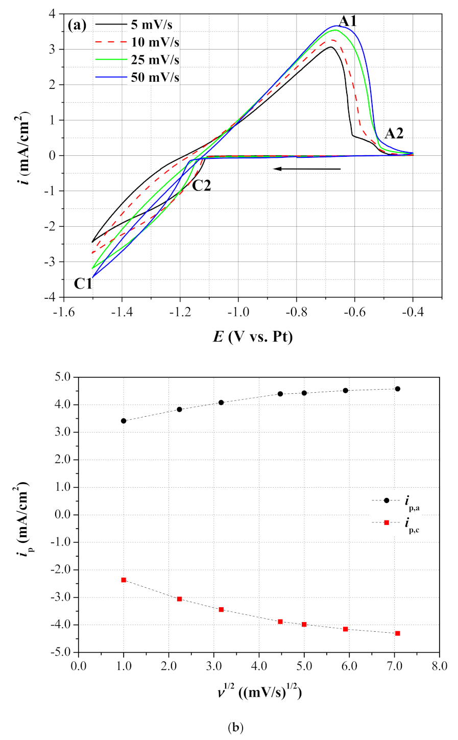
3.2. Determination of the Deposition Potential and Reversibility

Figure 3a shows CVs at four different scan rates. Figure S1 (Supplementary Materials) shows the CVs for the full set of seven scan rates. Electrodeposition (reduction) of aluminum starts at ca. −1.1 V vs. QRE (C2), reaching its peak at C1 [17]. During the reverse scan, Al stripping starts at −1.1 V. The anodic peak A1 (between −0.66 and −0.68 V vs. Pt, depending on the scan rate) can be related to the oxidation potential of aluminum in the studied cell conditions. The broad range of anodic stripping may indicate that different aluminum complexes form (A2 at slow scan rate), leading to a change in the ratio of the different aluminum species as the potential is scanned in the positive direction. It should be noted that the anodic dissolution of Al in ILs might be quite a complexed process, as reported for [EMIm]Cl-based ILs, where different mechanisms were observed at different overpotentials [22,49,50]. When the cathodic potential reached −1.6 V, a dull black deposit was evident on the substrate’s surface. Based on EDS analysis, it contained elements, such as carbon, sulfur, and fluorine, in addition to a low amount of aluminum. These elements originated from the IL, as a result of its decomposition. This deposit masked mass transport phenomena, limiting the current of the main reaction. Neither a nucleation loop [51,52], sometimes termed crossover, or a trace crossing due to an autocatalytic process [53,54], is apparent in the CVs at scan rates of 5, 10, and 25 mV/s, implying, among other things, that the deposition of Al on the Ni substrate does not require overpotential to initiate the nucleation and growth of deposits. However, it should be noted that such a nucleation loop trace crossing exists both in the CV at 50 mV/s on the Ni substrate and in the CVs on the Cu substrate (not shown herein).
The reaction kinetics were evaluated based on the effect of the potential scan rate ν (in V/s), on the A1 anodic peak and C1 cathodic peak current densities (ip). Figure 3b shows the peak current densities dependence on ν1/2. The anodic plot seems to have two slopes: one within the range of ν = 1 to 20 mV/s, and the other within the range of ν = 20 to 50 mV/s. Indeed, while the coefficient of determination R2 of the linear fit of the entire range of scan rate was 0.91831, it increased to 0.99214 for the range of 1 to 20 mV/s (in both cases, the pre-fix intercept was not forced to equal zero). The corresponding R2 values for the cathodic plot were 0.9385 and 0.98352, respectively. In addition, the ratio between the anodic peak current and the cathodic peak current (namely, C1, i.e., the lowest potential in the CV) decreased from 1.44 to 1.06 as the scan rate increased from 1 to 50 mV/s. The separation of the peak potentials (ΔEp = Ep,aEp,c) increased with the sweep rate, from 815.7 to 837.1 mV at ν = 1 and 50 mV/s. These values are significantly higher than the theoretical value of 56.5 mV/n for a fully reversible reaction at T = 298 K [55].

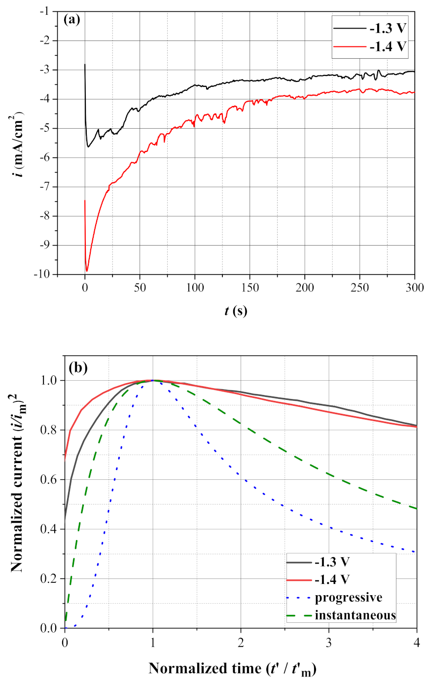
3.3. Nucleation and Growth

Chronoamperometry [8] yields current transients. Based on this, Scharifker et al. [56,57] derived equations that describe the 3D nucleation mechanisms with crystal growth controlled by localized hemispherical diffusion [58]. Two extreme cases of nucleation kinetics were represented: instantaneous nucleation and progressive nucleation. Instantaneous nucleation corresponds to a slow growth of nuclei on a small number of active sites, all activated at the same time. On the other hand, progressive nucleation corresponds to a fast growth of nuclei on many active sites, all activated during the progression of electrodeposition. The following equations were derived:
i 2 i m 2 = 1.9542 t m t 1 exp 1.2564 t t m 2 instantaneous
i 2 i m 2 = 1.2254 t m t 1 exp 2.3367 t 2 t m 2 2 progressive
where im and tm are the current density and time coordinates of the chronoamperometric peak, respectively. These equations are sometimes drawn using dimensional times t′ and t m , replacing t and tm, respectively. In this case, t′ = tt0 and t m = t m t 0 , where t0 is the time at im. Equations (1) and (2) were employed successfully in the study of electrodeposition [59,60,61], including of Al from ILs [34,62,63].
Figure 4a presents the experimental chronoamperometric transients at various applied potentials, while Figure 4b presents the normalized curves for two different applied potentials and their comparison to Scharifker’s model (Equations (1) and (2)). From Figure 4b, it is evident that the electrodeposition of Al on Ni is characterized by instantaneous nucleation, similarly to previous work on electrodeposition of Al on glassy carbon [34,63], W [62,63,64], Cu [65], and Al [64]. Compared to the instantaneous nucleation model, the higher experimental normalized currents may result from parasitic current as well as from the inhibition effect associated with free Cl ions in the processes of reduction and the change in species and complexes in solution [66].

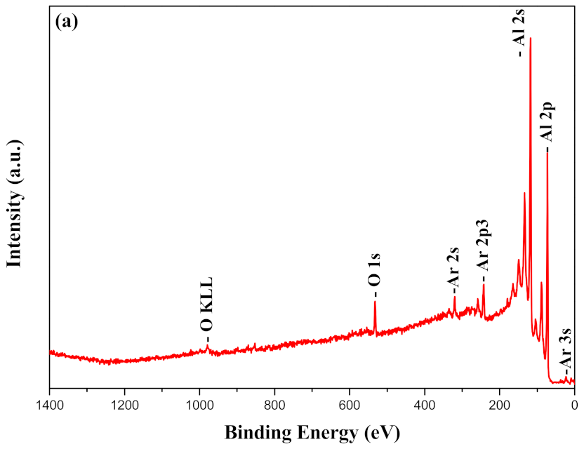
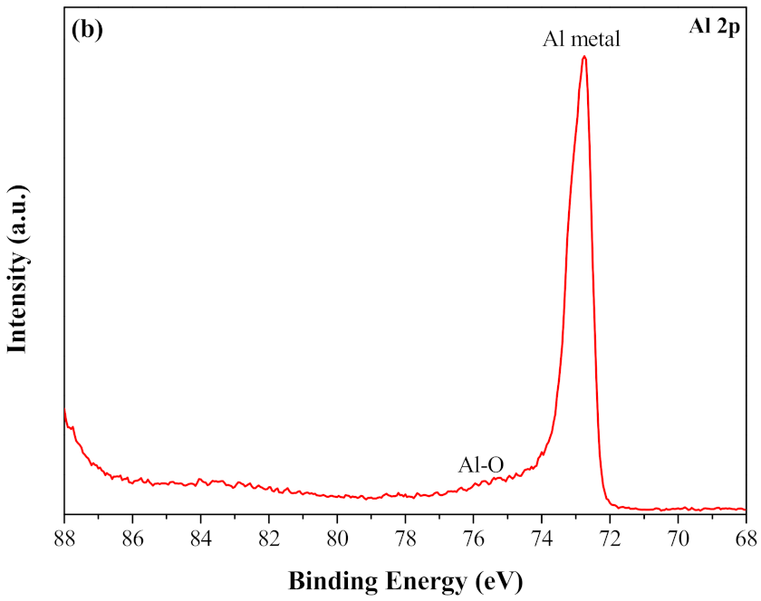
3.4. The Surface Chemistry of the Coating

The EDS chemical composition (in wt.%) of coatings deposited on Ni at different potentials are listed in Table 1. It is evident that all coatings are rich in Al (pure Al in the case of samples E46 and E50). The Cl in sample E40 probably originated from AlCl3 crystals on the surface, while the O in samples E52 and E40 is most likely a result of spontaneous oxidation of the reactive aluminum metal during handling of the coated samples before they were characterized by SEM-EDS. In the case of sample E46, Ni from the substrate was also evident (not shown herein), indicating that the coating was thinner than that on sample E50, where no Ni from the substrate was evident.
XPS was used to further characterize the surface chemistry of the coatings. Before sputtering, the surface of sample E52 contained (in at.%) 39.28 C, 34.41 O, 13.71 Al, 7.18 Si, 2.19 Cl, 1.56 F, 0.84 N, and 0.83 S. In contrast, after sputtering, the composition changed to 81.76 Al, 15.55 O, 2.12 N, and 0.57 F. While N may originate from both the [HMIm] cation and the [TFSI] anion, F could be derived from the [TFSI] anion only. It has been reported that elements associated with IL anions in general, including F in the specific case of [TFSI], may be present in the XPS spectra in significant quantities [67]. Sputtering was determined to be sufficient when the at.% of Al and O plateaued (after 5.7 min). A layer of Al2O3 on Al, which was evident in the high-resolution spectrum (at 75.6 eV [65]), was slowly removed by sputtering. The presence of oxygen was, thus, evident, both from EDS and from XPS data. One explanation of the XPS data could be that mixing during the sputtering process pushed some of the oxygen ions at the surface back into the metallic coating. It could also be that some Al2O3 formed by a parasitic reaction in parallel to metallic Al deposition. The high-resolution Al 2p peak after sputter cleaning clearly revealed the presence of metallic Al. The survey and high-resolution Al 2p spectra acquired after Ar sputtering from sample E46 are shown in Figure 5a,b, respectively. This sample contained (in at.%) 94.84 Al and 5.16 O at its surface after sputter cleaning.

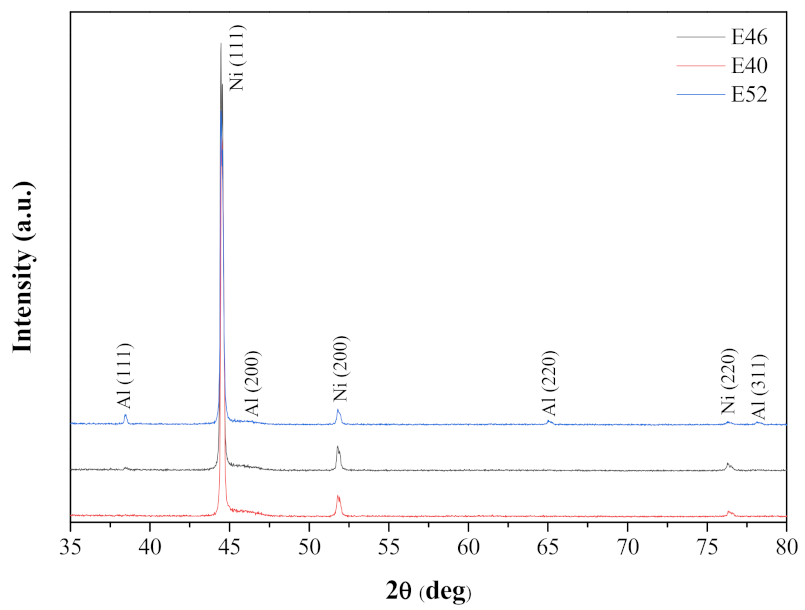
3.5. The Crystal Structure of the Al Coating

Figure 6 presents the XRD patterns of aluminum coatings on nickel substrates (samples E40, E46 and E52). All reflections match those of pure, cubic (FCC) metallic Al (card No. 04-012-7848) with a lattice parameter of a = 4.05 Å. The average crystal size, based on the full width at half maximum (FWHM) of the most intense peak and the Scherrer’s equation, is 60 nm.
Several TEM samples were examined in order to assess the quality of the as-grown Al layers. First, the composition of the layers was checked by EDS analysis which pointed on pure Al. Figure 7 shows typical images and a SAED pattern taken from these samples. The deposited layer is polycrystalline, originating a ring electron diffraction pattern (see Figure 7c). Since all reflections appearing in the SAED pattern could be indexed according to the Al structure, it was concluded that no additional phases were present. Furthermore, the only structural defects, which were observed, are dislocations appearing with typical density for Al metal (approaching 108 dislocations/cm2 [68]). In addition, stress that was evident in the Ni substrate did not seem to affect the Al layer. Finally, the value of the lattice parameter determined based on TEM characterization matches well the one determined by XRD.
The substrate–layer interface was smooth, without a heteroepitaxial relationship (based on SAED). It can be seen that the substrate consists of 0.2–1-μm grains, which tend to be close to equiaxed (see Figure 7b), while the Al layer consists of mostly columnar grains (single crystals), varying in size as a function of distance from the substrate. Close to the substrate, the Al layer consists of nano-sized cubical grains, 20–100 nm in width, while further away, the width reaches 0.5 μm. The existence of small crystals at the interface most probably helped to reduce the strains in the Al coating, as similarly reported for other systems, such as GaN [69]. The thickness of the Al layer was found to change as a function of deposition conditions; it was larger than 2 μm and 470–570 nm for E52 and E46 samples, respectively.

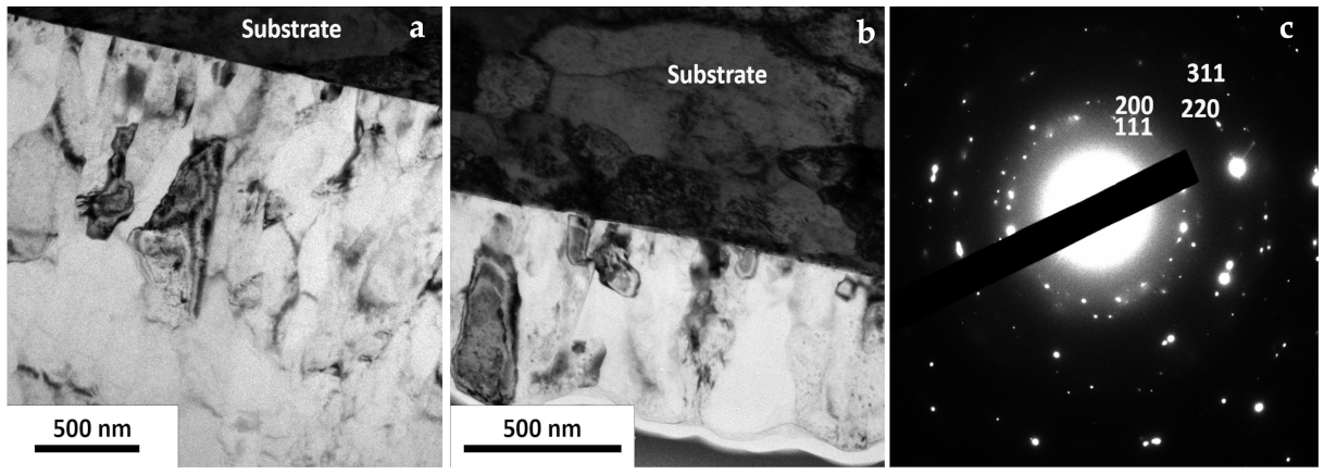
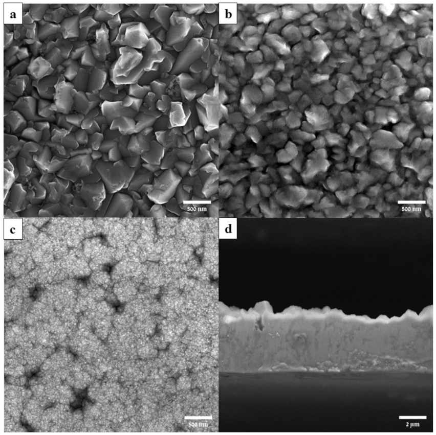
3.6. Surface Morphology of the Al Coating

Figure 8 shows the macroscopic appearance of Al coatings on Ni and Cu substrates. A grayish, dense, and uniform coating with good surface coverage is evident in both cases. Figure 9 shows both the top view (a–c) and the cross-section view (d) of Al coatings deposited under different potentials. Fairly dense and uniform crystalline coatings are evident. A similar surface morphology was reported before for Al electrodeposition from ILs containing light aromatic naphta [10]. It should be considered that the surface morphology of electrodeposits typically vary with the passed charge (C/cm2) during the electrodeposition process. Therefore, these values are provided in the caption of Figure 9. The grain size ranges from several hundred nanometers at −1.3 V down to several dozen nanometers at −1.5 V. Image analysis of SEM cross-section images gave deposition rates of 11.0 ± 3.8, 36.0 ± 5.8, and 734.0 ± 0.1 nm/min for coatings deposited at −1.3, −1.4, and −1.5 V, respectively. The same deposition rate was measured after a 20- and 120-min deposition period, indicating a constant rate which likely reflects a faradaic behavior.

4. Discussion

In this paper, we report room-temperature electroplating of pure nanocrystalline aluminum on copper and nickel substrates from an [HMIm][TFSI]–AlCl3 room-temperature ionic liquid (RTIL). For the first time, this RTIL is used for electroplating of Al.
Knowledge on the ionic species in the IL is important for fundamental understanding of the electrochemical reactions. Liquid-state 1H NMR analysis of the as-received [HMIm][TFSI] reagent revealed the [HMIm] cation, but no water impurity, which is quite common in ILs due to their hygroscopic nature [70,71]. ESI HRMS revealed [HMIm]+, [TFSI], [[TFSI]2Na], [AlCl4], [FeCl4] , and [FeCl3], but no nickel ions, other complexes, organic compounds, or chlorination of the hexyl chain of [HMIm]+.
It is well known that several aluminum–chlorine complexes may coexist in equilibrium in solution, namely [AlCl4], [Al2Cl7], [Al3Cl10], and [Al4Cl13] [22,72,73]. Some thermodynamic equilibrium parameters are provided elsewhere [73]. For AlCl3–[EMIm]AlCl4 (1:5), it was shown that only [AlCl4] and [Al2Cl7] coexist at 30 °C (80 and 20 mol%, respectively). It was argued that, while [AlCl4] cannot be reduced to Al, [Al2Cl7] is the electroactive species for Al deposition, according to the reaction:
4 Al 2 Cl 7 + 3 e Al + 7 AlCl 4
The so-generated [AlCl4] then migrates to the anode [73,74]. Since the molar ratio of AlCl3/[HMIm]Cl in our system is higher than 1 (i.e., Lewis acid), [AlCl4] tends to further complex with AlCl3, thus forming [Al2Cl7]. The following chemical equilibrium reaction can also be drawn:
2 AlCl 4 Al 2 Cl 7 +   Cl
It has been commonly argued that Al cannot be electrodeposited from basic electrolytes since the organic cations are reduced at less negative potentials than the dominant [AlCl4] anions [17].
Careful selection of the anion–cation system in this study made the electrodeposition of Al preferential, whereas lower solution polarization enhanced the solubility of the AlCl3 precursor [59], thus increasing the acidity of the solution [4]. Consequently, the concentration of the electroactive species [Al2Cl7] should have been increased, enhancing the electrodeposition process. Surprisingly, no peaks appear in any of the ESI ES spectra at m/z = 275.5 or 302.1, which could have been the footprint of [Al2Cl7]. One could argue that all [Al2Cl7] was consumed during electrodeposition; however, the same spectra were obtained from both used and freshly prepared RTIL. Another argument could be that the reactive [Al2Cl7] decomposed during the ionization process in the mass spectrometer. In this line, it has been reported that [Al2Cl7] anions are not observed in the MS-negative mode spectra of neutral ligand-based ILs [75], while related positive clusters (e.g., [AlCl2]+ at m/z ≈ 97) appear in the ES+ spectra [75,76]. Optimization of the MS instrumental conditions helped getting good agreement between mass spectral, potentiometric, and 27Al NMR data [76]. It has also been argued that asymmetric cleavage of AlCl3 (instead of direct coupling with [AlCl4] to form [Al2Cl7]) generates [AlCl2]+ and [AlCl4], and that the former is coordinated by a ligand [77]. Electrodeposition from Al-containing cations could be beneficial for electrodeposition of Al, compared to conventional ILs [77]. Before concluding the discussion of ionic species, it should also be noted that, in addition to aluminum-chlorine complexes, some other species may exist in the chloro-[bis(trifloromethanesulfunayl)imid]-aluminum system [78].
A biphasic appearance characterized the as-prepared IL in this study. A similar biphasic behavior has been observed in [cation][(CF3SO2)2N]–AlCl3 liquid mixtures [78] within a certain AlCl3 concentration range. The lower phase in that case was colorless, more viscous, with no cation signals. The upper phase, on the other hand, contained the organic cation and a mixture of chloro-[bis(trifluoromethanesulfonyl)imide]-aluminate ions.
The reaction kinetics were evaluated based on the effect of the potential scan rate on the C1 cathodic peak current density and the A1 anodic peak current density (Figure 3a,b). Similar analyses of both cathodic (forward scan) and anodic (backward scan) peaks have been used for aluminum deposition and dissolution in ILs [17,22,79,80]. Several reaction types are discussed extensively in the literature, including the following [8,60,81,82,83,84].
(a) A reversible (fast) reaction, implying that charge transfer is easy and occurs frequently whenever an analyte molecule approaches the electrode. In this case, the peak current density is proportional to ν1/2 according to the Randles-Ševćik:
i p = 0.4463 n F A C n F D R T 1 / 2 ν 1 / 2
where n is the number of electrons transferred in the redox reaction, A is the electrode surface area (cm2), C is the bulk molar concentration of the electroactive species (mol/cm3), D is the diffusion coefficient of the electroactive species (cm2/s), T is the thermodynamic temperature (K), F is Faraday’s constant (C/mol), and R is the molar gas constant (J/K/mol).
(b) An irreversible (slow) electron exchange, including chemical transformations of charge transfer products. In this case too, the peak current density is proportional to ν1/2, according to:
i p = 2 . 99 × 1 0 5 α n 1 / 2 A C D 1 / 2 ν 1 / 2
where α is the transfer coefficient.
(c) A quasi-reversible (slow) reaction, in which the current is controlled by both charge transfer and mass transport.
(d) A capacitive (non-faradaic) current due to charging of the electric double layer. In this case, the current is proportional to ν, according to:
i nF = A C dl ν
Hence, based on cyclic voltammetry measurements, the current seems to be controlled by both charge transfer and mass transport (diffusion) of the electroactive species (see Figure 3b). This coupled effect reflects a quasi-reversible reaction [84]. The fact that the line in Figure 3b does not intercept with the origin, as expected for a simple diffusion controlled process, indicates a contribution of a side reaction in the non-purified IL. Similar conclusions were drawn in previous studies of electrodeposition of Al from ILs [79,80,85]. Finally, the value of separation of peak potentials (which is affected by Ohmic drop, i.e., by resistance polarization) is significantly higher than the theoretical value and increases with the sweep rate. This, per se, indicates kinetic limitations of charge transfer.
Chronoamperometry measurements showed that the electrocrystallization of Al on Ni is characterized by instantaneous nucleation (Figure 4b). Higher experimental normalized currents, compared to the instantaneous nucleation model, may result from parasitic current as well as from the inhibition effect associated with free Cl ions in the processes of reduction and the change in species and complexes in solution [66].
SEM–EDS analysis showed that all coatings were rich in Al, and, in some cases, were made of pure Al (Table 1). O and Cl impurities were detected in some deposits. TEM–EDS analysis of FIB-made samples revealed only Al. Therefore, it may be that the O and Cl detected by SEM–EDS were concentrated at the surface of the sample and were related to impurities and handling. XPS indeed revealed Cl before sputtering, but none after sputtering (Figure 5a). However, N that could originate from both the [HMIm] cation and the [TFSI] anion, as well as F that could originate from the [TFSI] anion only, were also detected by XPS, also after sputtering. This could be an indication of a side reaction, as also indicated by cyclic voltammetry and chronoamperometry. Despite the aforementioned impurities, XPS clearly showed that the coating consisted of Al in its metallic form, and not in an oxidized form (see Figure 5b).
Macroscopic inspection (Figure 8), SEM (Figure 9), and TEM (Figure 7) showed that the deposited Al layers were dense, homogeneous, and of good surface coverage. Their microstructure was further characterized by both XRD (Figure 6) and TEM (Figure 7). The substrate–layer interface was smooth, without heteroepitaxial relationship. Stress that was evident in the Ni substrate did not seem to affect the Al layer, probably thanks to the formation of small crystals at the interface. Both XRD and TEM proved that the deposited layers consisted of a single phase of metallic FCC Al with a polycrystalline structure (see Figure 6 and Figure 7c). A good match was obtained between the value of the lattice parameter, as determined by XRD and TEM. It should be considered that electrodeposition, by definition, is a non-equilibrium process that takes place under a cathodic overpotential. Consequently, electrodeposits often contain metastable phases, phases that are either deficient or oversaturated in the content of a component, or phases with unexpected crystal structure [86,87,88,89].
The size of the columnar grains ranged from several hundred nanometers at −1.3 V down to several dozen nanometers at −1.5 V. Regarding defects, only dislocations were observed by TEM, with dislocations density typical of Al metal. Because the stacking fault energy of Al is very high, the growth of twins in Al is unlikely. Yet, Rafailović et al. [90] recently reported a high density of genuine growth twins in Al electrodeposited galvanostatically at 20 mA/cm2 and 85 °C for 30 min from [EMIm]Cl IL.
An increase in the applied cathodic potential from −1.3 to −1.5 V vs. Pt resulted in more than one order of magnitude increase in the deposition rate, from 0.66 to 44.04 μm/h. The upper value falls within the typical range of deposition rates in industrial applications of other coating systems. Because the same deposition rate was measured after the 20- and 120-min deposition periods, one can argue that the deposition follows a faradaic behavior. Finally, an increase in the applied cathodic potential from −1.3 to −1.5 V vs. Pt also resulted in ca. one order of magnitude finer grain size. This trend is in line with some other reports of deposition of Al from ILs, whereas the cathodic overpotential was increased and the average radius of grains decreased [91].
The main advantages of the electrodeposition process used herein are that it is simple and economic compared to some other industrial processes, provides easy control of the process, is conducted at room temperature, can coat non-line-of-site areas and geometrically complex structures, and yields good surface coverage as well as a pure and dense aluminum layer with controllable thickness. Its main limitations, however, are that one has to avoid the humidity and oxygen in air, for example by carrying out the deposition inside a glovebox. Further work is required to optimize the process and characterize film properties, such as electrical conductivity and adhesion to the substrate.
The coating developed in this work may be used in a variety of applications, such as electrochemical 3D printing, solar and display panels, circuit boards, radar array components, connectors, targeting mirrors, micro-electro-mechanical systems (MEMS), fasteners, car body parts, fittings, thermal actuators, etc.

5. Conclusions

In this paper, we reported electroplating of pure aluminum from a room-temperature ionic liquid (RTIL) on copper and nickel substrates. The RTIL, used here for the first time for electroplating of Al, was composed of 1-Hexyl-3-methylimidazolium (HMIm) cation, bis(trifluoromethylsulfonyl)imide (TFSI) anion, and a high concentration of 8 mol/L of AlCl3 aluminum precursor. Cyclic voltammetry measurements indicated that the electron exchange reaction was quasi-reversible, with the current being affected by both charge transfer and mass transport (i.e., diffusion of the electroactive species in the solution). Chronoamperometry measurements showed that the electrocrystallization of Al on Ni is characterized by instantaneous nucleation. Cyclic voltammetry, chronoamperometry, and XPS indicated possible effects of a side reaction. The deposited Al layers were dense, homogeneous, and of good surface coverage. They had a nanocrystalline, single-phase Al (FCC) structure, with a dislocation density typical of Al metal. An increase in the applied cathodic potential from −1.3 to −1.5 V vs. Pt resulted in more than one order of magnitude increase in the deposition rate (to ca. 44 μm per hour), as well as in ca. one order of magnitude finer grain size.

Supplementary Materials

The following are available online at https://www.mdpi.com/article/10.3390/coatings11111414/s1, Figure S1: Cyclic voltammograms for a Ni substrate in [HMIm][TFSI]–(8 M)AlCl3 at room temperature and the full set of sweep rates.

Author Contributions

Conceptualization, Y.M. and N.E.; methodology, Y.M. and N.E.; formal analysis, Y.M., N.M., L.M., and N.E.; investigation, Y.M. and L.M.; resources, N.E. and L.M.; data curation, Y.M., N.M., L.M., and N.E.; writing—original draft preparation, Y.M. and N.E.; writing—review and editing, N.E., L.M., and N.M.; visualization, N.E.; supervision, N.E.; funding acquisition, N.E. All authors have read and agreed to the published version of the manuscript.

Funding

This research was funded by both the Israel Ministry of Defense (grant no. 4440783376) and the Innovation Authority (Magneton grant no. 65140).

Institutional Review Board Statement

Not applicable.

Informed Consent Statement

Not applicable.

Data Availability Statement

The data presented in this study are available on request from the corresponding author.

Acknowledgments

We thank Pini Shekhter and Davide Levi from the Wolfson Applied Materials Research Centre at Tel-Aviv University for XPS and XRD measurements and data analysis, respectively. We also thank Noam Tal from the Mass Spectrometry Lab and Sarit Slovak Ben Shabtay from the NMR Labs, both in the School of Chemistry, for conducting the mass spectrometry and NMR tests of the solutions, respectively.

Conflicts of Interest

The authors declare no conflict of interest.

References

  1. Saevarsdottir, G.; Kvande, H.; Welch, B.J. Aluminum production in the times of climate change: The global challenge to reduce the carbon footprint and prevent carbon leakage. JOM 2020, 72, 296–308. [Google Scholar] [CrossRef]
  2. Cullen, J.M.; Allwood, J.M. Mapping the global flow of aluminum: From liquid aluminum to end-use goods. Environ. Sci. Technol. 2013, 47, 3057–3064. [Google Scholar] [CrossRef] [Green Version]
  3. Milovanoff, A.; Posen, I.D.; MacLean, H.L. Quantifying environmental impacts of primary aluminum ingot production and consumption: A trade-linked multilevel life cycle assessment. J. Ind. Ecol. 2021, 25, 67–78. [Google Scholar] [CrossRef]
  4. Maniam, K.K.; Paul, S.A. Review on the electrodeposition of aluminum and aluminum alloys in ionic liquids. Coatings 2021, 11, 80. [Google Scholar] [CrossRef]
  5. Eliyahu, D.; Gileadi, E.; Galun, E.; Eliaz, N. Atomic force microscope-based meniscus-confined three-dimensional electrodeposition. Adv. Mater. Technol. 2020, 5, 1900827. [Google Scholar] [CrossRef]
  6. Svetlizky, D.; Zheng, B.; Buta, T.; Zhou, Y.; Golan, O.; Breiman, U.; Haj-Ali, R.; Schoenung, J.M.; Lavernia, E.J.; Eliaz, N. Directed energy deposition of Al 5xxx alloy using Laser Engineered Net Shaping (LENS®). Mater. Des. 2020, 192, 108763. [Google Scholar] [CrossRef]
  7. Eliaz, N.; Fuks, N.; Geva, D.; Oren, S.; Shriki, N.; Vaknin, D.; Fishman, D.; Levi, O. Comparative quality control of titanium alloy Ti–6Al–4V, 17–4 PH stainless steel, and aluminum alloy 4047 either manufactured or repaired by Laser Engineered Net Shaping (LENS®). Materials 2020, 13, 4171. [Google Scholar] [CrossRef] [PubMed]
  8. Eliaz, N.; Gileadi, E. Physical Electrochemistry: Fundamentals, Techniques, and Applications, 2nd ed.; Wiley-VCH: Weinheim, Germany, 2019; Ch. 17 & 18; ISBN 978-3-527-34139-9. [Google Scholar]
  9. Peled, E.; Gileadi, E. The electrodeposition of aluminum from aromatic hydrocarbon. I. Composition of baths and the effect of additives. J. Electrochem. Soc. 1976, 123, 15–19. [Google Scholar] [CrossRef]
  10. Guinea, E.; Salicio-Paz, A.; Iriarte, A.; Grande, H.-J.; Medina, E.; García-Lecina, E. Robust aluminum electrodeposition from ionic liquid electrolytes containing light aromatic naphta as additive. ChemistryOpen 2019, 8, 1094–1099. [Google Scholar] [CrossRef] [PubMed] [Green Version]
  11. Tsuda, T.; Hussey, C.L. Electrochemistry of room-temperature ionic liquids and melts. In Modern Aspects of Electrochemistry; White, R., Ed.; Springer: New York, NY, USA, 2009; No. 45. [Google Scholar]
  12. Ispas, A.; Bund, A. Electrodeposition in ionic liquids. Electrochem. Soc. Interface 2014, 23, 47–51. [Google Scholar] [CrossRef] [Green Version]
  13. Zein El Abedin, S.; Pölleth, M.; Meiss, S.A.; Janek, J.; Endres, F. Ionic liquids as green electrolytes for the electrodeposition of nanomaterials. Green Chem. 2007, 9, 549–553. [Google Scholar] [CrossRef]
  14. Tiago, G.A.O.; Matias, I.A.S.; Ribeiro, A.P.C.; Martins, L.M.D.R.S. Application of ionic liquids in electrochemistry—Recent advances. Molecules 2020, 25, 5812. [Google Scholar] [CrossRef] [PubMed]
  15. Kar, M.; Plechkova, N.V.; Seddon, K.R.; Pringle, J.M.; MacFarlane, D.R. Ionic liquids—Further progress on the fundamental issues. Aust. J. Chem. 2019, 72, 3–10. [Google Scholar] [CrossRef] [Green Version]
  16. Abbott, A.P.; McKenzie, K.J. Application of ionic liquids to the electrodeposition of metals. Phys. Chem. Chem. Phys. 2006, 8, 4265–4279. [Google Scholar] [CrossRef] [PubMed]
  17. Jiang, T.; Chollier Brym, M.J.; Dubé, G.; Lasia, A.; Brisard, G.M. Electrodeposition of aluminium from ionic liquids: Part I—electrodeposition and surface morphology of aluminium from aluminium chloride (AlCl3)–1-ethyl-3-methylimidazolium chloride ([EMIm]Cl) ionic liquids. Surf. Coat. Technol. 2006, 201, 1–9. [Google Scholar] [CrossRef]
  18. Liu, Q.X.; Zein El Abedin, S.; Endres, F. Electrodeposition of nanocrystalline aluminum: Breakdown of imidazolium cations modifies the crystal size. J. Electrochem. Soc. 2008, 155, D357–D362. [Google Scholar] [CrossRef]
  19. Bakkar, A.; Neubert, V. A new method for practical electrodeposition of aluminium from ionic liquids. Electrochem. Commun. 2015, 51, 113–116. [Google Scholar] [CrossRef]
  20. Ispas, A.; Wolff, E.; Bund, A. An electrochemical quartz crystal microbalance study on electrodeposition of aluminum and aluminum-manganese alloys. J. Electrochem. Soc. 2017, 164, H5263–H5270. [Google Scholar] [CrossRef]
  21. Böttcher, R.; Valitova, A.; Ispas, A.; Bund, A. Electrodeposition of aluminium from ionic liquids on high strength steel. Trans. IMF 2019, 97, 82–88. [Google Scholar] [CrossRef]
  22. Böttcher, R.; Mai, S.; Ispas, A.; Bund, A. Aluminum deposition and dissolution in [EMIm]Cl-based ionic liquids—Kinetics of charge-transfer and the rate-determining step. J. Electrochem. Soc. 2020, 167, 102516. [Google Scholar] [CrossRef]
  23. Böttcher, R.; Ispas, A.; Bund, A. Determination of transport parameters in [EMIm]Cl–based ionic liquids—Diffusion and electrical conductivity. Electrochim. Acta 2021, 366, 137370. [Google Scholar] [CrossRef]
  24. Yoshimura, K.; Miyahara, K.; Matsunaga, M. Electrodeposition of aluminum from ionic liquids. ECS Trans. 2009, 16, 449–452. [Google Scholar] [CrossRef]
  25. Karuppasamy, K.; Theerthagiri, J.; Vikraman, D.; Yim, C.-J.; Hussain, S.; Sharma, R.; Maiyalagan, T.; Qin, J.; Kim, H.-S. Ionic liquid-based electrolytes for energy storage devices: A brief review on their limits and applications. Polymers 2020, 12, 918. [Google Scholar] [CrossRef] [Green Version]
  26. Zhu, N.; Zhang, K.; Wu, F.; Bai, Y.; Wu, C. Ionic liquid-based electrolytes for aluminum/magnesium/sodium-ion batteries. Energy Mater. Adv. 2021, 2021, 9204217. [Google Scholar] [CrossRef]
  27. Holbrey, J.D.; Reichert, W.M.; Rogers, R.D. Crystal structures of imidazolium bis(trifluoromethanesulfonyl)imide ‘ionic liquid’ salts: The first organic salt with a cis-TFSI anion conformation. Dalton Trans. 2004, 2004, 2267–2271. [Google Scholar] [CrossRef]
  28. Bonhôte, P.; Dias, A.P.; Papageorgiou, N.; Kalyanasundaram, K.; Grätzel, M. Hydrophobic, highly conductive ambient-temperature molten salts. Inorg. Chem. 1996, 35, 1168–1178. [Google Scholar] [CrossRef]
  29. Hayley, A.E.; Andrea, G.B.; Douglas, R.M.; Greger, O.; Maria, F. Room temperature fast-ion conduction in imidazolium halide salts. J. Mater. Chem. 2001, 11, 3031–3036. [Google Scholar]
  30. Holbrey, J.D.; Seddon, K.R. The phase behaviour of 1-alkyl-3-methylimidazolium tetrafluoroborates; ionic liquids and ionic liquid crystals. J. Chem. Soc. Dalton Trans. 1999, 13, 2133–2139. [Google Scholar] [CrossRef]
  31. Paredes, X.; Queirós, C.S.G.P.; Santos, F.J.V.; Santos, A.F.; Santos, M.S.C.S.; Lourenço, M.J.V.; Nieto de Castro, C.A. Thermophysical properties of 1-hexyl-3-methylimidazolium bis(trifluoromethylsulfonyl)imide, [C6mim][(CF3SO2)2N]—New data, reference data, and reference correlations. J. Phys. Chem. Ref. Data 2020, 49, 043101. [Google Scholar] [CrossRef]
  32. Nazet, A.; Sokolov, S.; Sonnleitner, T.; Makino, T.; Kanakubo, M.; Buchner, R. Densities, viscosities, and conductivities of the imidazolium ionic liquids [Emim][Ac], [Emim][FAP], [Bmim][BETI], [Bmim][FSI], [Hmim][TFSI], and [Omim][TFSI]. J. Chem. Eng. Data 2015, 60, 2400–2411. [Google Scholar] [CrossRef]
  33. Liu, S.; Liedel, C.; Tarakina, N.V.; Ostic, N.C.; Akcora, P. Dynamics of ionic liquids in the presence of polymer-grafted nanoparticles. Nanoscale 2019, 11, 19832–19841. [Google Scholar] [CrossRef] [PubMed]
  34. Łachwa, J.; Morgado, P.; Esperança, J.M.S.S.; Guedes, H.J.R.; Canongia Lopes, J.N.; Rebelo, L.P.N. Fluid-phase behavior of {1-Hexyl-3-methylimidazolium bis(trifluoromethylsulfonyl) imide, [C6mim][NTf2], + C2−C8n-alcohol} mixtures:  liquid−liquid equilibrium and excess volumes. J. Chem. Eng. Data 2006, 51, 2215–2221. [Google Scholar] [CrossRef]
  35. Abbott, A.P.; Harris, R.C.; Hsieh, Y.-T.; Ryder, K.S.; Sun, I.-W. Aluminium electrodeposition under ambient conditions. Phys. Chem. Chem. Phys. 2014, 16, 14675–14681. [Google Scholar] [CrossRef]
  36. Barrado, E.; Rodriguez, J.A.; Hernández, P.; Castrillejo, Y. Electrochemical behavior of copper species in the 1-buthyl-3-methyl-imidazolium chloride (BMIMCl) ionic liquid on a Pt electrode. J. Electroanal. Chem. 2016, 768, 89–101. [Google Scholar] [CrossRef] [Green Version]
  37. Galiński, M.; Lewandowski, A.; Stępniak, I. Ionic liquids as electrolytes. Electrochim. Acta 2006, 51, 5567–5580. [Google Scholar] [CrossRef]
  38. Torriero, A.A.J.; Sunarso, J.; Howlett, P.C. Critical evaluation of reference systems for voltammetric measurements in ionic liquids. Electrochim. Acta 2012, 82, 60–68. [Google Scholar] [CrossRef]
  39. Yamato, Y.; Katayama, Y.; Miura, T. Effects of the interaction between ionic liquids and redox couples on their reaction entropies. J. Electrochem. Soc. 2013, 160, H309–H314. [Google Scholar] [CrossRef]
  40. Damodaran, K. Recent NMR studies of ionic liquids. Annu. Rep. NMR Spectrosc. 2016, 88, 215–244. [Google Scholar]
  41. Kaupilla, T.J.; Kostiainen, R. Ambient mass spectrometry in the analysis of compounds of low polarity. Anal. Methods 2017, 9, 4936–4953. [Google Scholar] [CrossRef]
  42. Steckel, A.; Schlosser, G. An organic chemist’s guide to electrospray mass spectrometric structure elucidation. Molecules 2019, 24, 611. [Google Scholar] [CrossRef] [Green Version]
  43. Babij, N.R.; McCusker, E.O.; Whiteker, G.T.; Canturk, B.; Choy, N.; Creemer, L.C.; De Amicis, C.V.; Hewlett, N.M.; Johnson, P.L.; Knobelsdorf, J.A.; et al. NMR chemical shifts of trace impurities: Industrially preferred solvents used in process and green chemistry. Org. Process Res. Dev. 2016, 20, 661–667. [Google Scholar] [CrossRef]
  44. Gottlieb, H.E.; Kotlyar, V.; Nudelman, A. NMR chemical shifts of common laboratory solvents as trace impurities. J. Org. Chem. 1997, 62, 7512–7515. [Google Scholar] [CrossRef]
  45. Urabe, T.; Tanaka, M.; Kumakura, S.; Tsugoshi, T. Study on chemical speciation in aluminum chloride solution by ESI-Q-MS. J. Mass Spectrom. 2007, 42, 591–597. [Google Scholar] [CrossRef] [PubMed]
  46. Hellman, H.; Laitinen, R.S.; Kaila, L.; Jalonen, J.; Hietapelto, V.; Jokela, J.; Sarpola, A.; Ramo, J. Identification of hydrolysis products of FeCl3·6H2O by ESI-MS. J. Mass Spectrom. 2006, 41, 1421–1429. [Google Scholar] [CrossRef] [PubMed]
  47. Zarzana, C.A.; Groenewold, G.S.; Benson, M.T.; Delmore, J.; Tsuda, T.; Hagiwara, R. Iron fluoroanions and their clusters by electrospray ionization of a fluorinating ionic liquid. J. Am. Soc. Mass Spectrom. 2015, 26, 1559–1569. [Google Scholar] [CrossRef]
  48. Kruve, A.; Kaupmees, K.; Liigand, J.; Oss, M.; Leito, I. Sodium adduct formation efficiency in ESI source. J. Mass Spectrom. 2013, 48, 695–702. [Google Scholar] [CrossRef] [PubMed]
  49. Wang, C.; Creuziger, A.; Stafford, G.; Hussey, C.L. Anodic dissolution of aluminum in the aluminum chloride-1-Ethyl-3-methylimidazolium chloride ionic liquid. J. Electrochem. Soc. 2016, 163, H1186–H1194. [Google Scholar] [CrossRef] [Green Version]
  50. Böttcher, R.; Ispas, A.; Bund, A. Anodic dissolution of aluminum and anodic passivation in [EMIm]Cl-based ionic liquids. Electrochem. Commun. 2020, 115, 106720. [Google Scholar] [CrossRef]
  51. Heinze, J.; Rasche, A.; Pagels, M.; Geschke, B. On the origin of the so-called nucleation loop during electropolymerization of conducting polymers. J. Phys. Chem. B 2007, 111, 989–997. [Google Scholar] [CrossRef]
  52. Yang, M.; Hu, Z. Electrodeposition of bismuth onto glassy carbon electrodes from nitrate solutions. J. Electroanal. Chem. 2005, 583, 46–55. [Google Scholar] [CrossRef]
  53. Andrieux, C.P.; Merz, A.; Saveant, J.M. Dissociative electron transfer. Autocatalysis and kinetic characteristics of the electrochemical reductive cleavage of the carbon halogen bond in alkyl halides giving rise to stable radicals and carbanions. J. Am. Chem. Soc. 1985, 107, 6097–6103. [Google Scholar] [CrossRef]
  54. Houmam, A.; Hamed, E.M. Application of the dissociative electron transfer theory and its extension to the case of in-cage interactions in the electrochemical reduction of arene sulfonyl chlorides. Phys. Chem. Chem. Phys. 2012, 14, 113–124. [Google Scholar] [CrossRef] [PubMed]
  55. Bard, J.A.; Faulkner, L.R. Electrochemical Methods: Fundamentals and Applications, 2nd ed.; John Wiley and Sons: New York, NY, USA, 2001. [Google Scholar]
  56. Scharifker, B.; Hills, G. Theoretical and experimental studies of multiple nucleation. Electrochim. Acta 1983, 28, 879–889. [Google Scholar] [CrossRef]
  57. Scharifker, B.R.; Mostany, J.; Palomar-Pardavé, M.; González, I. On the theory of the potentiostatic current transient for diffusion-controlled three-dimensional electrocrystallization processes. J. Electrochem. Soc. 1999, 146, 1005–1012. [Google Scholar] [CrossRef]
  58. Budevski, E.; Staikov, G.; Lorenz, W.J. Electrochemical Phase Formation and Growth: An Introduction to the Initial Stages of Metal Deposition; VCH: Weinheim, Germany, 1996. [Google Scholar]
  59. Barrosse-Antle, L.E.; Bond, A.M.; Compton, R.G.; O’Mahony, A.M.; Rogers, E.I.; Silvester, D.S. Voltammetry in room temperature ionic liquids: Comparisons and contrasts with conventional electrochemical solvents. Chem. Asian J. 2010, 5, 202–230. [Google Scholar] [CrossRef] [PubMed]
  60. Eliaz, N.; Eliyahu, M. Electrochemical processes of nucleation and growth of hydroxyapatite on titanium supported by real-time electrochemical atomic force microscopy. J. Biomed. Mater. Res. A 2007, 80, 621–634. [Google Scholar] [CrossRef]
  61. Grujicic, D.; Pesic, B. Electrodeposition of copper: The nucleation mechanisms. Electrochim. Acta 2002, 47, 2901–2912. [Google Scholar] [CrossRef]
  62. Carlin, R.T.; De Long, H.C.; Fuller, J.; Trulove, P.C. Microelectrode evaluation of transition metal-aluminum alloy electrodepositions in chloroaluminate ionic liquids. J. Electrochem. Soc. 1998, 145, 1598–1607. [Google Scholar] [CrossRef]
  63. Lee, J.-J.; Miller, B.; Shi, X.; Kalish, R.; Wheeler, K.A. Aluminum deposition and nucleation on nitrogen-incorporated tetrahedral amorphous carbon electrodes in ambient temperature chloroaluminate melts. J. Electrochem. Soc. 2000, 147, 3370–3376. [Google Scholar] [CrossRef]
  64. Jiang, T.; Chollier Brym, M.J.; Dubé, G.; Lasia, A.; Brisard, G.M. Electrodeposition of aluminium from ionic liquids: Part II—studies on the electrodeposition of aluminum from aluminum chloride (AlCl3)—Trimethylphenylammonium chloride (TMPAC) ionic liquids. Surf. Coat. Technol. 2006, 201, 10–18. [Google Scholar] [CrossRef]
  65. Yong, Z.; Suojiang, Z.; Xingmei, L.; Qian, W.; Yong, Z.; Lian, L. Low-temperature electrodeposition of aluminium from Lewis acidic 1-Allyl-3 methylimidazolium chloroaluminate ionic liquids. Chin. J. Chem. Eng. 2012, 20, 130–139. [Google Scholar]
  66. Sherstyuk, O.V.; Pron’kin, S.N.; Chuvilin, A.L.; Salanov, A.N.; Savinova, E.R.; Tsirlina, G.A.; Petrii, O.A. Platinum electrodeposits on glassy carbon: The formation mechanism, morphology, and adsorption properties. Russ. J. Electrochem. 2000, 36, 741–751. [Google Scholar] [CrossRef]
  67. Theivaprakasam, S.; Girard, G.; Howlett, P.; Forsyth, M.; Mitra, S.; MacFarlane, D. Passivation behaviour of aluminium current collector in ionic liquid alkyl carbonate (hybrid) electrolytes. npj Mater. Degrad. 2018, 2, 13. [Google Scholar]
  68. Ohring, M. Engineering Materials Science; Academic Press: London, UK, 1995; Ch. 7; pp. 299–370. [Google Scholar]
  69. Meshi, L.; Cherns, D.; Griffiths, I.; Khongphetsak, S.; Gott, A.; Liu, C.; Denchitcharoen, S.; Shields, P.; Wang, W.; Campion, R.P.; et al. The reduction of threading dislocations in GaN using a GaN nanocolumn interlayer. Phys. Stat. Sol. (c). 2008, 5, 1645–1647. [Google Scholar] [CrossRef]
  70. Stark, A.; Behrend, P.; Braun, O.; Müller, A.; Ranke, J.; Ondruschk, B.; Bernd Jastorff, B. Purity specification methods for ionic liquids. GreenChem. 2008, 10, 1152–1161. [Google Scholar] [CrossRef]
  71. Andanson, J.-M.; Meng, X.; Traïkia, M.; Husson, P. Quantification of the impact of water as an impurity on standard physico-chemical properties of ionic liquids. J. Chem. Thermodyn. 2016, 94, 169–176. [Google Scholar] [CrossRef]
  72. Trémillon, B.; Letisse, G. Proprietes en solution dans le tetrachloroaluminate de sodium fondu I. systemes “acide-base”. J. Electroanal. Chem. Interfacial Electrochem. 1968, 17, 371–386. [Google Scholar] [CrossRef]
  73. Shi, M.; Jiang, J.; Zhao, H. Electrodeposition of aluminum in the 1-Ethyl-3-Methylimidazolium Tetrachloroaluminate ionic liquid. Electrochem 2021, 2, 185–196. [Google Scholar] [CrossRef]
  74. Berretti, E.; Giaccherini, A.; Martinuzzi, S.M.; Innocenti, M.; Schubert, T.J.S.; Stiemke, F.M.; Caporali, S. Aluminium electrodeposition from ionic liquid: Effect of deposition temperature and sonication. Materials 2016, 9, 719. [Google Scholar] [CrossRef]
  75. Sakhalkar, M.; Aduri, P.; Lande, S.; Chandra, S. Single-step synthesis of novel chloroaluminate ionic liquid for green Friedel–Crafts alkylation reaction. Clean Technol. Environ. Policy 2020, 22, 59–71. [Google Scholar] [CrossRef]
  76. Cvijović, M.; Kilibarda, V.; Jelikić-Stankov, M.; Lazarević, I.; Jakovljević, I.; Joksović, L.; Đurđević, P. ESI-MS study of speciation in hydrolyzed aluminum chloride solutions. J. Braz. Chem. Soc. 2012, 23, 1087–1097. [Google Scholar] [CrossRef] [Green Version]
  77. Fang, Y.; Yoshii, K.; Jiang, X.; Sun, X.G.; Tsuda, T.; Mehio, N.; Dai, S. An AlCl3 based ionic liquid with a neutral substituted pyridine ligand for electrochemical deposition of aluminum. Electrochim. Acta 2015, 160, 82–88. [Google Scholar] [CrossRef]
  78. Brausch, N.; Metlen, A.; Wasserscheid, P. New, highly acidic ionic liquid systems and their application in the carbonylation of toluene. Chem. Commun. 2004, 13, 1552–1553. [Google Scholar] [CrossRef] [PubMed]
  79. Bakkar, A.; Neubert, V. Electrodeposition and corrosion characterisation of micro- and nano-crystalline aluminium from AlCl3/1-ethyl-3-methylimidazolium chloride ionic liquid. Electrochim. Acta 2013, 103, 211–218. [Google Scholar] [CrossRef]
  80. Zhang, L.P.; Ge, Z.W.; Yu, X.J.; Zhao, Z.D.; Dong, Y.H. Al electrodeposition from chloroaluminate ionic liquid. Canad. Metall. Quart. 2013, 52, 398–404. [Google Scholar] [CrossRef]
  81. Sandford, C.; Edwards, M.A.; Klunder, K.J.; Hickey, D.P.; Li, M.; Barman, K.; Sigman, M.S.; White, H.S.; Minteer, S.D. A synthetic chemist’s guide to electroanalytical tools for studying reaction mechanisms. Chem. Sci. 2019, 10, 6404–6422. [Google Scholar] [CrossRef] [Green Version]
  82. Nicholson, R.S.; Shain, I. Theory of stationary electrode polarography: Single scan and cyclic methods applied to reversible, irreversible, and kinetic systems. Anal. Chem. 1964, 36, 706–723. [Google Scholar] [CrossRef]
  83. Sisso, O.; Dor, S.; Eliyahu, D.; Sabatani, E.; Eliaz, N. Corrosion inhibition of copper in ferric chloride solution with organic inhibitors. npj Mater. Degrad. 2020, 4, 38. [Google Scholar] [CrossRef]
  84. Elwell, D.; Rao, G.M. Mechanism of electrodeposition of silicon from K2SiF6–flinak. Electrochim. Acta 1982, 27, 673–676. [Google Scholar] [CrossRef]
  85. Wen, X.; Zhang, J.; Luo, H.; Tsay, C.; Jiang, H.; Lin, Y.-H.; Schroeder, M.A.; Guo, J. Synthesis and electrochemical properties of an aluminum hexafluorophosphate electrolyte. J. Phys. Chem. Lett. 2021, 12, 5903–5908. [Google Scholar] [CrossRef]
  86. Baik, S.-I.; Duhin, A.; Phillips, P.J.; Klie, R.F.; Gileadi, E.; Seidman, D.N.; Eliaz, N. Atomic-scale structural and chemical study of columnar and multilayer Re–Ni electrodeposited thermal barrier coating. Adv. Eng. Mater. 2016, 18, 1133–1144. [Google Scholar] [CrossRef]
  87. Cohen Sagiv, M.; Eliaz, N.; Gileadi, E. Incorporation of iridium into electrodeposited rhenium–nickel alloys. Electrochim. Acta 2013, 88, 240–250. [Google Scholar] [CrossRef]
  88. Hegde, A.C.; Venkatakrishna, K.; Eliaz, N. Electrodeposition of Zn–Ni, Zn–Fe and Zn–Ni–Fe alloys. Surf. Coat. Technol. 2010, 205, 2031–2041. [Google Scholar] [CrossRef]
  89. Eliaz, N.; Venkatakrishna, K.; Hegde, A.C. Electroplating and characterization of Zn–Ni, Zn–Co and Zn–Ni–Co alloys. Surf. Coat. Technol. 2010, 205, 1969–1978. [Google Scholar] [CrossRef]
  90. Rafailović, L.D.; Gammer, C.; Ebner, C.; Rentenberger, C.; Jovanović, A.Z.; Pašti, I.A.; Skorodumova, N.V.; Karnthaler, H.P. High density of genuine growth twins in electrodeposited aluminum. Sci. Adv. 2019, 5, eaax3894. [Google Scholar] [CrossRef] [PubMed] [Green Version]
  91. Peng, Y.; Shinde, P.S.; Reddy, R.G. Diffusion coefficient and nucleation density studies on electrochemical deposition of aluminum from chloroaluminate ionic liquid electrolytes. J. Electroanal. Chem. 2021, 895, 115363. [Google Scholar] [CrossRef]
Figure 1. 1H NMR spectrum of the as-received [HMIm][TFSI] dissolved in CDCl3. The molecular structures of TFSI (top) and HMIm (bottom) are shown in the top left corner. The a-to-h indexing of the peaks in the spectrum correspond to the markings on the molecular structure of HMIm.
Coatings 11 01414 g001
Figure 2. ESI HRMS spectra of a freshly prepared 8 M [HMIm][TFSI]–AlCl3 solution diluted with acetonitrile. (ac) negative ions mode, (d) positive ions mode.
Coatings 11 01414 g002aCoatings 11 01414 g002bCoatings 11 01414 g002cCoatings 11 01414 g002d
Figure 3. (a) Cyclic voltammograms for a Ni WE in [HMIm][TFSI]–(8 M)AlCl3 at room temperature and at different scan rates. (b) The dependence of the anodic and cathodic peak current densities (ip) on the square root of the scan rate (ν1/2).
Coatings 11 01414 g003
Figure 4. (a) Chronoamperometry current vs. time transients for deposition potentials of −1.3 and −1.4 V. Sampling rate: 5 Hz. (b) Normalized experimental curves (solid lines) compared to those predicted by Scharifker’s models for instantaneous nucleation (Equation (1), dashed green line) and progressive nucleation (Equation (2), dotted blue line).
Coatings 11 01414 g004
Figure 5. (a) XPS survey spectrum acquired from sample E46 after 5.7 min sputtering. (b) High-resolution Al 2p peak after sputtering.
Coatings 11 01414 g005aCoatings 11 01414 g005b
Figure 6. XRD patterns of Al coatings deposited under different potentials on Ni substrates. See Table 1 for sample identification.
Coatings 11 01414 g006
Figure 7. (a,b) Bright-field TEM images of samples E52 and E46, respectively, with different thickness of the as-grown Al layer. The Ni substrate is marked. Dark dots in the Al layer are originated from Ga irradiation during sample preparation in the FIB. (c) A typical SAED pattern taken from the Al layer on sample E52. This polycrystalline pattern is indexed according to the Al structure ( F m 3 ¯ m , a = 4.04 Å).
Coatings 11 01414 g007
Figure 8. CCD images of Al electrodeposits (bottom parts) on Ni and Cu substrates. Deposition potential: −1.3 V.
Coatings 11 01414 g008
Figure 9. Top view (ac) and cross-section view (d) of Al coatings deposited under different potentials: (a) sample E52 (−1.3 V, 12.6 C/cm2), (b) sample E46 −1.45 V, 2.2 C/cm2), (c) sample E40 (−1.5 V, 3.0 C/cm2), and (d) sample E34 (−1.3 V, 120 min, 13.9 C/cm2). See Table 1 for further information.
Coatings 11 01414 g009
Table 1. EDS chemical composition (wt.%) of coatings deposited at different potentials.
Sample IDPotential (V)Time (min)AlOCl
E52−1.312097.42.6-
E50−1.420100.0--
E46−1.4520100.0--
E40−1.52093.53.03.5
Publisher’s Note: MDPI stays neutral with regard to jurisdictional claims in published maps and institutional affiliations.

