
Sol–Gel Encapsulation of ZnAl Alloy Powder with Alumina Shell


Department of Materials Science and Engineering, Tel-Aviv University, Tel Aviv 6997801, Israel
*
Author to whom correspondence should be addressed.
Coatings 2021, 11(11), 1389; https://doi.org/10.3390/coatings11111389
Submission received: 27 September 2021
/
Revised: 5 November 2021
/
Accepted: 12 November 2021
/
Published: 14 November 2021
(This article belongs to the Special Issue Recent Developments of Electrodeposition Coatings II)
Abstract
:Additive manufacturing (AM), for example, directed energy deposition (DED), may allow the processing of self-healing metal–matrix composites (SHMMCs). The sealing of cracks in these SHMMCs would be achieved via the melting of micro-encapsulated low melting point particulates (LMPPs), incorporated into the material during AM, by heat treatment of the part during service. Zn-Al alloys are good candidates to serve as LMPPs, for example, when the matrix of the MMC is made of an aluminum alloy. However, such powders should first be encapsulated by a thermal and diffusion barrier. Here, we propose a sol–gel process for encapsulation of a custom-made ZA-8 (Zn92Al8, wt.%) core powder in a ceramic alumina (Al2O3) shell. We first modify the surface of the ZA-8 powder with (12-phosphonododecyl)phosphonic acid (Di-PA) hydrophobic self-assembled monolayer (SAM) in order to prevent extensive hydrogen evolution and formation of non-uniform and porous oxide/hydroxide surface layers during the sol–gel process. Calcination for 1 h at 500 °C is found to be insufficient for complete boehmite-to-γ(Al2O3) phase transformation. Thermal stability tests in an air-atmosphere furnace at 600 °C for 1 h result in melting, distortion, and sintering into a brittle sponge (aggregate) of the as-atomized powder. In contrast, the core/shell powder is not sintered and preserves its spherical morphology, with no apparent “leaks” of the ZA-8 core alloy out of the ceramic encapsulation.
1. Introduction
The field of self-healing materials has been dominated by polymer-based materials, mainly because chemical reactions in polymers produce a significant energy release and massive diffusional processes. These are feasible even at room temperature, thus allowing the design of self-healing agents that are autonomously activated and transported to sites of damage localization [1,2].
Most structural metals degrade via irreversible mechanisms such as fatigue, creep, wear, etc. All of these limit the service lifetime of the component and might lead to catastrophic failure. The concept of metallic-based self-healing materials has thus attracted a rapid increase in interest in recent years, yet it is at its infancy. Metallic-based self-healing materials present various potential advantages over polymer-based self-healing materials. As opposed to polymer-based self-healing materials, metallic-based materials can potentially repair the damage of high-strength metallic-based structural parts subjected to high static loads, dynamic fatigue loading, creep, and serve in extreme environments and elevated temperatures. Furthermore, the emergence of metallic-based self-healing materials plays a significant role from a sustainability point of view [1]. The potential economic and ecological benefits associated with the re-use of structural metallic-based parts that have been damaged and out of service is tremendous in numerous applications.
The main challenges in facilitating effective healing in metal-based materials include high melting temperatures, low diffusivities, oxidation, and complex fabrication [3,4]. Nevertheless, there has been some progress in the development of self-healing metals. To date, most research conducted on self-healing metals has focused on either solid-state diffusional healing of micro-cracks or liquid-assisted healing as a means to repair macro-cracks.
A potentially attractive processing route for self-healing metal–matrix composites (SHMMCs) is directed energy deposition (DED) additive manufacturing (AM). Towards this goal, we have designed the following concept material system: (1) A matrix made of Al 5xxx alloy (Al alloy series, where Mg is the principle alloying element). We have already demonstrated the successful DED of an Al 5754-O alloy with high density and good mechanical properties by Laser Engineered Net Shaping (LENS®) [5,6]. A transition from an Al 5083 gas atomized powder feedstock to Al 5754 characteristics of the as-deposited material due to selective evaporation of Mg was reported [5,6]. (2) Shape memory alloy (SMA) wire reinforcement that will facilitate mechanical crack volume reduction by pulling the crack together in response to external heating (taking advantage of its shape memory effect). (3) Micro-encapsulated low melting point particulates (LMPPs), which should not dissolve in the matrix during AM, but should be melted by heat treating the part during service, flow into adjacent cracks as a result of the action of capillary forces, and seal the cracks. The LMPP should be homogenously dispersed in the Al-based powder stock before printing in order to achieve proper deposition of the MMC.
It is quite challenging to print high-quality Al-based alloys by laser-based AM [5,7]. Relatively high laser energy densities might be required to deposit the Al matrix. However, this high energy will likely also melt the LMPP, thus forming new phases with unwanted characteristics, which might prevent successful healing of the matrix. A solution to such a problem could be to encapsulate the LMPP core powder with: (1) a reflective metallic shell that will decrease the amount of laser energy absorbed in the LMMP powder during laser-based AM [8,9], (2) metallic outer shell that will serve as a thermal barrier at high temperatures [10], or (3) a high-temperature ceramic shell, which will serve as both thermal and diffusion barrier between the Al-based matrix and the LMPP.
Zn-Al alloys are zinc casting alloys suitable for applications requiring high as-cast strength, hardness, and wear resistance [8]. Here, we use a core powder with a chemical composition Zn92Al8 (wt.%), known as ZA-8 [8,11], as an LMPP. This LMPP was selected based on its physical, metallurgical, and mechanical properties and their match with those of an Al 5083 matrix (see Table 1).
Here, we propose a sol–gel process for encapsulation of the ZA-8 core powder in a ceramic alumina (Al2O3) shell. When a crack propagates through the MMC, the brittle ceramic shell should be cracked too, allowing the release of melted ZA-8 to seal the crack during a controlled heat treatment. This type of healing design may allow to facilitate MMC healing under much lower temperatures (say, ~390 °C) than previously reported healing treatments of Al SHMMC (e.g., 592 °C for partial melting of an Al–3Si matrix [13,14]), thus preventing the degradation of both the SMA reinforcement and the metallic matrix.
2. Materials and Methods
2.1. Powder Synthesis and Characterization
The ZA-8 prealloyed powder feedstock was synthesized by a gas atomization process by TLS Technik GmbH & Co. Spezialpulver KG (Bitterfeld-Wolfen, Germany), especially for this study.
Powder characterization was performed to confirm the quality of the custom-made powders in terms of chemical composition and powder sphericity and size distribution. Inductively coupled plasma optical emission spectrometry (ICP-OES, PlasmaQuant PQ9000, Analytik Jena AG, Jena, Germany) was utilized to determine the chemical composition of the as-received feedstock powder. The so-obtained chemical composition was given in Table 1 in Ref. [8]. The particle size distribution (PSD) and sphericity of the as-received powder was measured using via dynamic image analysis (DIA) using a QICPIC system with a RODOS/L dry dispersion unit (Sympatec GmbH, Clausthal-Zellerfeld, Germany). The sample size was 6.1 g, the light source frequency was 400 Hz, and the dispersion pressure was 0.50 bar. In this test, high-speed image analysis is carried out using a pulsed light source with illumination times of less than 1 ns. The particles are optically frozen while a high-resolution, high-speed camera captures the particle projections with a frequency of up to 500 frames per second. An algorithm is then applied to evaluate the captured particles size distribution and sphericity. Sessile drop (static) contact angle (CA) measurements were conducted at room temperature (T = 20 °C) on powder particles before and after formation of a self-assembled monolayer (SAM). To this aim, a Krüss DSA25S system with ADVANCE software ver. 1.7.1.0 (Hamburg, Germany) was used. After placing a 6 μL deionized (DI) water drop on the surface, the CA was measured three times. Average values are reported herein.
Metallographic samples for cross-section analysis by both light microscopy and scanning electron microscopy (SEM) were prepared by cold mounting the powder particles in acrylic resin (Struers, Copenhagen, Denmark), followed by mechanical grinding on 1200, 2500, and 4000 grit SiC papers. Final mechanical polishing was carried out on a cloth wetted with 1 μm diamond suspension. The morphology of the powder particles and their local chemical composition were characterized before and after micro-encapsulation in alumina using a SEM (Quanta 200 FEG, FEI, Waltham, MA, USA) equipped with an energy-dispersive X-ray spectrometer (EDS, INCA detector, Oxford Instruments, Abington, UK). X-ray photoelectron spectroscopy (XPS) was used to determine the chemical analysis and oxidation states at the surface of the ZA-8 powder, before and after encapsulation in alumina. XPS measurements were performed in UHV (2.5 × 10⁻¹⁰ Torr base pressure) using 5600 Multi-Technique system (Physical Electronics, Inc. (PHI), Chanhassen, MN, USA). The samples were irradiated with an Al-Kα monochromated source, and the outcome electrons were analyzed by a spherical capacitor analyzer using the slit aperture of 0.8 mm. The samples were analyzed at the surface only, i.e., without sputter cleaning. Sample charging was compensated with a charge neutralizer, and C1s at 285.0 eV was taken as an energy reference for all the peaks.
2.2. Application of a SAM on the Surface of the ZA-8 Powder Prior to Deposition of Alumina
The alumina shell was formed in this study by a sol–gel process. However, due to the very negative electrode potential of Zn, extensive hydrogen evolution accompanies the dissolution of zinc in aqueous solutions [15]. In addition, non-uniform and porous oxide/hydroxide surface layers are formed during oxidation reactions in aqueous media, making it very difficult to apply coatings chemically/electrochemically on zinc and its alloys. Only recently was a successful electroless deposition of metals on zinc-based powders demonstrated, for the first time [8,9]. It should be borne in mind that when scaling-up and working with large batches of powder having a high surface area, serious hydrogen safety concerns (namely, spontaneous ignition and explosion) might appear.
To address this issue, we first modified the surface of the ZA-8 powder with (12-phosphonododecyl)phosphonic acid (Di-PA) SAM, following protocols that were described elsewhere [16,17]. This SAM molecule was chosen mainly due to its long hydrophobic chain, which will provide a barrier between the zinc surface and the aqueous solution. At the same time, this molecule can promote bonding to both the ZA-8 powder and the boehmite shell, thanks to its hydrophilic tail groups. Phosphonate monolayers were reported to react with the (native) oxide layer at the surface of metals and alloys, which involves the formation of ionocovalent P–O–M bonds by condensation of P–OH groups with surface M–OH groups [18]. The ZA-8 powder was immersed in 15 mM Di-PA in tetrahydrofuran (THF) solution at room temperature for 24 h while stirring the solution, followed by rinsing in ethanol and drying at 70 °C in ambient conditions.
2.3. Sol–Gel Processing of the Alumina Outer Shell
Preliminary experiments with Al-Isopropoxide precursor solution did not yield high-quality, continuous and adherent shells. In contrast, a precursor solution based on aluminum sec-butoxide (ASB, Al[OCH(CH3)C2H5]3) [19] yielded good results, as shown below. The preparation of the sol–gel solution was based on procedures reported elsewhere [19,20,21]. In brief, the sol–gel process consisted of two distinct reactions:
- (1)
- Hydrolysis of the alcohol groups at 50 °C:
- (2)
- Condensation and polymerization of the resulting hydroxyl groups:
- (3)
- Finally, a calcination reaction at 400–500 °C in air is conducted to convert the boehmite (aluminum oxide monohydrate, Al2O3·H2O, also known as γ-AlOOH) to alumina:
Boehmite is known to form γ-Al2O3 when calcined at 300–500 °C, δ-Al2O3 when calcined at 700–800 °C, θ-Al2O3 at 900–1000 °C, before transforming into α-Al2O3 (corundum) above 1000 °C [22,23,24,25].
The process steps were thus as follows:
- ASB was added to DI water pre-heated to 50 °C at a molar ratio of 1:80 under vigorous mechanical stirring.
- A small amount of nitric acid was added to maintain the pH of the suspension at ~4.0.
- The suspension was stirred vigorously for 15 min, until a homogenous sol was formed.
- The SAM-modified powder was added to the sol, continue vigorous stirring for 15 min.
- The product was washed employing centrifugation in ethanol.
- The product was then dried at 100 °C for 12 h in air and calcined at 350–500 °C for 1 h. Both heating and cooling rates were 1 °C/min.
A schematic illustration of both the SAM surface modification process and the ZA-8 powder sol–gel encapsulation process is presented in Figure 1.
3. Results and Discussion
3.1. Characterization of the As-Atomized ZA-8 Powder
ICP-OES chemical analysis of the as-atomized powder revealed that it contained 91.0 wt.% Zn, 7.8 wt.% Al, 1.1 wt.% Cu, and some Mg, Fe, Sn and Pb impurities (Table 1 in Ref. [8]). XPS analysis of the surface of the as-atomized powder before sputter-cleaning revealed in the current study the elements Al, Zn, and Mg, in addition to high concentrations of O and C. We have already reported [8] that the ZnAl powder consists of a hcp Zn phase, in addition to some Al0.52Zn0.48 solid solution phase. Native Al2O3 was identified by XRD on the surface of the untreated ZnAl particles. Differential scanning calorimetry (DSC) revealed one main endothermic peak at 382 °C [8], which was ascribed to the latent heat generated during melting of the ZnAl alloy [10].
Complementary characterization of this powder is provided herein. Figure 2 and Table 2 show the PSD and sphericity values of the as-atomized powder, as obtained from DIA. The definition of powder characteristics and comparison between different measurement techniques are discussed elsewhere [26,27,28]. Optomec’s guideline for LENS® DED is that the powder particles should be spherical (for good flowability) and with a size of −100/+325 mesh, equivalent to a powder diameter of 44 to 150 μm. It is thus evident from Figure 2 and Table 2 that the ZA-8 custom-made powder is suitable for DED.
An attempt to measure the sessile drop CA of DI water on an as-atomized powder bed failed due to rapid absorbance of water in the powder, which indicates that the unmodified powder is very hydrophilic. Microscopic characterization of the as-atomized powder is given below.
3.2. The SAM-Modified Powder—Contact Angle Measurements
Figure 3 shows two DI water drops in a static CA test—one on the Di-PA-modified powder bed and one still connected to the dispersing syringe. The measured CA was 140.9 ± 0.1°, indicating that the SAM successfully transformed the hydrophilic surface of the ZA-8 powder to a hydrophobic surface, as planned.
3.3. The Core/Shell ZA-8/Alumina Powder
As described in Section 2, the alumina shell was formed on the SAM-modified powder via a sol–gel process, followed by calcination in an air furnace for 1 h at 350–500 °C. No hydrogen evolution was evident during the sol–gel processing of the SAM-modified powder. SEM images of both the as-atomized powder’s surface and its cross-section are shown in Figure 4. Figure 4d clearly shows that no coating exists on the surface of the powder. The microstructure revealed in the cross-section is heterogeneous and is similar to that of cast ZA-8-based alloys [29,30]. It consists of primary β dendrites in a lamellar eutectic (α + η) matrix. The β phase, which is unstable below 275 °C, decomposed to form a Zn-rich η equilibrium phase and an Al-rich α equilibrium phase, following the eutectoid reaction in the Zn–Al binary phase diagram [31,32,33].
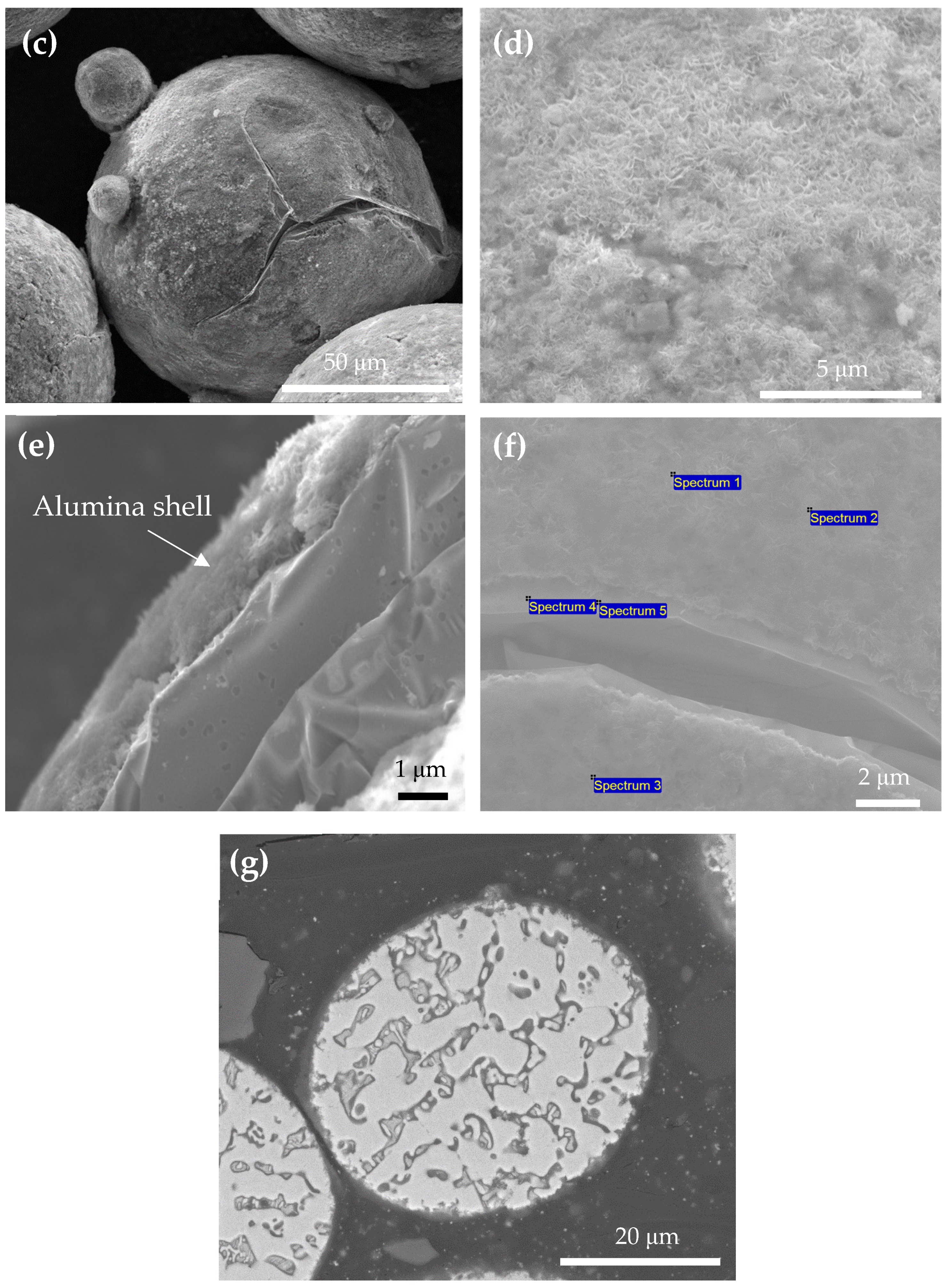
Figure 5 shows SEM images of the sol–gel processed and calcined (at 500 °C) powder, both of its outer surface and of its cross-section. Figure 5a shows powder particles after scale-up that allowed us to treat 100 g in each batch. No substantial aggregation is apparent. Figure 5b shows the surface morphology of a coated powder particle. Comparing with Figure 4a, it is evident that the surface became more compact after the sol–gel and calcination process. The surface morphology in Figure 5b resembles that of Al-Si microspheres after boehmite treatment (Figure 1b in Ref. [34]). Figure 5c shows a cracked particle. The crack formed during calcination at 500 °C, most likely due to (1) difference in the thermal expansion coefficients of the core and shell materials, and (2) thermal expansion of the ceramic shell caused by volume expansion of the core alloy due to its solid-to-liquid phase transition during calcination (see Ref. [34] and Figure 7c therein). Although the percentage of cracked particles was small, such cracking might degrade the properties of the SHMMC and be harmful to its functionality because it may allow the melted ZnAl alloy to flow from the LMPP into the surrounding (Al-based) matrix either during AM or heat treatment during service. Figure 5d is a top view revealing the surface morphology of the alumina shell. The presence of the coating on top of the core powder is clear. This surface morphology resembles that of Al-Si microspheres after boehmite treatment (Figure 1c in Ref. [34]). Figure 5e is a side view of a cracked zone, which reveals a conformal and uniform shell. The shell thickness was measured at different locations and was found to be ~1 μm. EDS spot analysis of the coated powder was carried out (Figure 5f and Table 3). Spectra 1–3 were acquired at well-coated areas, whereas spectra 4–5 were acquired at areas adjacent to a crack. A substantial increase in the oxygen concentration (accompanied by a decrease in the zinc concentration) is evident in alumina-coated areas compared with areas where the core alloy is exposed (despite its own native oxide layer revealed by XRD, as mentioned in Section 3.1). Figure 5g shows the microstructure at the cross-section of a particle after sol–gel processing and calcination at 500 °C. The microstructure is different than that of the as-atomized powder (compare with Figure 4d). The calcination temperature of 500 °C is higher than the melting point, both according to our own DSC results (see Section 3.1) and the liquidus line in the Zn–Al binary phase diagram at 8 wt.% Al [31,32,33]. It is apparent that the ZnAl core was melted during the calcination step, yet the molten alloy remained encapsulated by the ceramic shell.
XPS analysis of the as-atomized powder revealed a Zn 2p3/2 core-level peak at a binding energy (BE) of 1022.05 eV, an Al 2p peak at 74.4 eV, and an O 1s peak at 531.7 eV. After sol–gel and calcination processes, the concentrations of oxygen and aluminum at the surface (without sputter-cleaning) increased from 45.91 and 11.39 at.% to 54.30 and 21.93 at.%, respectively. A Zn 2p3/2 peak appeared at 1021.8 eV, an O 1s peak at 531.2 eV, and an Al 2p peak at 74.25 eV.
NIST [35] tabulated from different references BE of 1020.8 to 1022.10 eV for the Zn 2p3/2 peak. Moreover, Zn 2p3/2 binding energies of 1021.65 ± 0.01 eV and 1021.00 ± 0.04 eV were reported for Zn(O) and Zn(II) oxide, respectively, before using the modified Auger parameter [36]. O 1s BE values of 529.76 ± 0.04 eV and 531.25 ± 0.05 eV were reported for lattice Zn(II) oxide and hydroxide, hydrated, or defective oxygen, respectively [36]. This supports the claim that the outer layer on the powder is not zinc oxide. Furthermore, hydroxyl groups in the crystal structure or on the surface were correlated with O 1s BE of 531.9 eV [37]. BE of 74.9 eV has been reported for AlOx oxide on Al [38] as well as for Al2O3 in minerals [39], whereas BE of 74.0 to 74.6 eV has been reported for boehmite [40]. The binding energy of the 2p of metallic Al, for comparison, is 72.8 eV [41]. Nguefack et al. [41] prepared hydrated boehmite nano-sized crystallites through a sol–gel procedure. After calcination at 500 °C, XPS revealed BEs of the Al 2p and O 1s at 73.8 and 530.7 eV, respectively.
The Al 2p peaks acquired at the surfaces of both as-atomized and sol–gel-processed and calcined powders are shown in Figure 6a. Deconvolution and curve fitting of the Al 2p peak reveals the presence of two alumina phases: γ-Al2O3 (29.55% based on peak area, positioned at 74.50 eV) and boehmite (70.45%, 74.11 eV), see Figure 6b. The full width at half maximum (FWHM) is 2.45 eV in both cases. The presence of boehmite indicates that the boehmite-to-γ(Al2O3) phase transformation was not complete under the calcination conditions used in this study (1 h at 500 °C). Some studies used an annealing temperature as high as 600 °C and an annealing time as long as 20 h for this conversion [23,24].
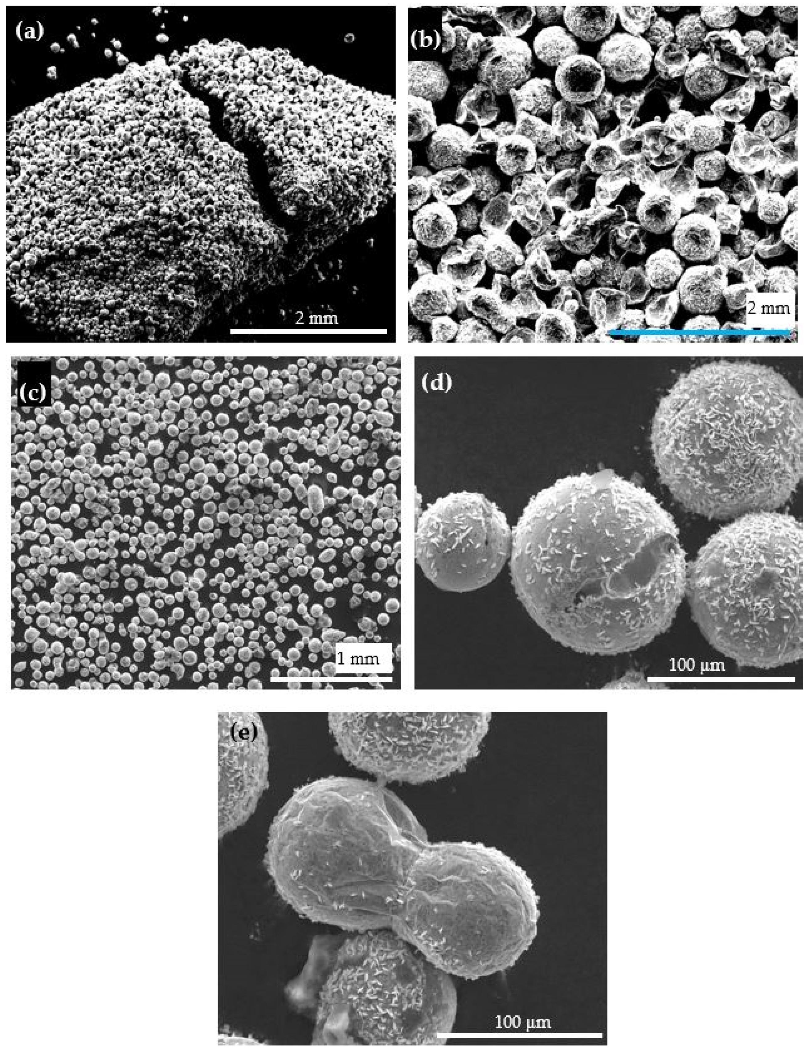
Thermal stability tests were run in an air-atmosphere furnace at 600 °C for 1 h. Similar quantities of as-atomized and ceramic coated ZA-8 powders were used for this purpose. The as-atomized powder was sintered into a brittle sponge (aggregate) (Figure 7a); many of its particles became distorted and lost their sphericity, including particles that were melted, leaving behind a distorted skin (Figure 7b). In contrast, the ceramic-coated powder was not sintered (Figure 7c). In addition, the core/shell powder preserved its spherical morphology (Figure 7c,d), with no apparent “leaks” of the ZA-8 core alloy out of the ceramic encapsulation.
Yet, some particles either have surface cavities (Figure 7d) or are sintered to one another (Figure 7e). Altogether, it thus seems that the ceramic shell satisfies its functional requirements. Further work is required in order to prove it in actual AM of the MMC.
In the present study, the encapsulated metal-based LMPP is designed to preserve the functionality of the LMPP material during AM fabrication and to serve as a reinforcement in an Al-based matrix that facilitates macro-cracks sealing upon external heat treatment. However, metal/ceramic-based core/shell-based materials are also attractive as high-temperature phase-changing materials (PCMs) used for thermal energy storage applications [34], such as building parts [42] and solar thermal power plants [43].
4. Conclusions
Here, we proposed a sol–gel process for encapsulation of a custom-made ZA-8 (Zn92Al8, wt.%) core powder in a ceramic alumina (Al2O3) shell. The surface of the ZA-8 powder was first modified with (12-phosphonododecyl)phosphonic acid (Di-PA) self-assembled monolayer (SAM), which made it hydrophobic and served as a barrier between the highly reactive zinc and the aqueous solution, thus preventing extensive hydrogen evolution and the formation of unwanted oxide/hydroxide surface layers during the sol–gel process. XPS analysis of the obtained alumina shell revealed that the shell material was composed of a mixture of 70.45% boehmite and 29.55% γ-alumina. This suggests that calcination for 1 h at 500 °C was insufficient for complete boehmite-to-γ(Al2O3) phase transformation.
Thermal stability tests in an air-atmosphere furnace at 600 °C for 1 h caused melting, distortion, and sintering into a brittle sponge (aggregate) of the as-atomized powder. In contrast, the core/shell powder preserved its spherical morphology, was not sintered, and did not show any apparent “leaks” of the ZA-8 core alloy out of the ceramic encapsulation. The functional coating system developed in this work may be used in a variety of applications, including additive manufacturing of self-healing metal–matrix composites, where crack sealing would be achieved via melting of the low melting point ZA-8 particulates (LMPPs) embedded in the matrix by heat treatment of the part during service.
Author Contributions
Conceptualization, D.S. and N.E.; methodology, D.S. and N.E.; investigation, D.S.; data curation, D.S.; visualization, D.S.; supervision, N.E.; resources, N.E.; funding acquisition, N.E.; project administration, N.E.; writing—original draft, N.E.; writing—review and editing, D.S. and N.E. All authors have read and agreed to the published version of the manuscript.
Funding
This research received partial funding from the Israel Ministry of Defense (Grant No. 4440783376).
Institutional Review Board Statement
Not applicable.
Informed Consent Statement
Not applicable.
Data Availability Statement
Data cannot be shared at this time since it is an ongoing R&D project.
Acknowledgments
The authors thank Larisa Burstein from the Wolfson Applied Materials Research Center for XPS analysis and Eliran Hamo for XRD measurements.
Conflicts of Interest
The authors declare no conflict of interest.
References
- Grabowski, B.; Tasan, C.C. Self-healing metals. In Self-Healing Materials. Advances in Polymer Science; Hager, M.D., van der Zwaag, S., Schubert, U.S., Eds.; Springer: Basel, Switzerland, 2016; Volume 273, pp. 387–407. [Google Scholar]
- Manuel, M.V. Design of a Biomimetic Self-Healing Alloy Composite. Ph.D. Thesis, Northwestern University, Evanston, IL, USA, 2007. [Google Scholar]
- Misra, S.K. Shape Memory Alloy Reinforced Self-Healing Metal Matrix Composites. Master’s Thesis, The University of Wisconsin-Milwaukee, Milwaukee, WI, USA, 2013. [Google Scholar]
- Ferguson, J.B.; Schultz, B.F.; Rohatgi, P.K. Self-healing metals and metal matrix composites. JOM 2014, 66, 866–871. [Google Scholar] [CrossRef]
- Svetlizky, D.; Zheng, B.; Buta, T.; Zhou, Y.; Golan, O.; Breiman, U.; Haj-Ali, R.; Schoenung, J.M.; Lavernia, E.J.; Eliaz, N. Directed energy deposition of Al 5xxx alloy using Laser Engineered Net Shaping (LENS®). Mater. Des. 2020, 192, 108763. [Google Scholar] [CrossRef]
- Eliaz, N.; Svetlizky, D.; Schoenung, J.; Lavernia, E.; Zhou, Y.; Zheng, B. Deposition of Al 5xxx Alloy Using Laser Engineered Net Shaping. International Patent Application PCT/US2020/065373, 16 December 2020. [Google Scholar]
- Eliaz, N.; Fuks, N.; Geva, D.; Oren, S.; Shriki, N.; Vaknin, D.; Fishman, D.; Levi, O. Comparative quality control of titanium alloy Ti–6Al–4V, 17–4 pH stainless steel, and aluminum alloy 4047 either manufactured or repaired by Laser Engineered Net Shaping (LENS). Materials 2020, 13, 4171. [Google Scholar] [CrossRef]
- Svetlizky, D.; Kazimierczak, H.; Ovadia, B.; Sharoni, A.; Eliaz, N. Electrochemical two-step encapsulation of ZnAl alloy microparticles with a metallic Ni-based shell. Materials 2021, 14, 834. [Google Scholar] [CrossRef]
- Eliaz, N.; Svetlizky, D.; Kazimierczak, H. Method for Forming Functional Coatings. U.S. Provisional Patent 63/093,535, 19 October 2020. [Google Scholar]
- Kawaguchi, T.; Sakai, H.; Sheng, N.; Kurniawan, A.; Nomura, T. Microencapsulation of Zn-Al alloy as a new phase change material for middle-high-temperature thermal energy storage applications. Appl. Energy 2020, 276, 115487. [Google Scholar] [CrossRef]
- Ferguson, J.B.; Schultz, B.F.; Rohatgi, P.K. Zinc alloy ZA-8/shape memory alloy self-healing metal matrix composite. Mater. Sci. Eng. A 2015, 620, 85–88. [Google Scholar] [CrossRef]
- Granta EduPack 2021; Granta Design: Cambridge, UK, 2021.
- Wright, M.C.; Manuel, M.; Wallace, T.; Newman, A.; Brinson, C. Self-Repairing Fatigue Damage in Metallic Structures for Aerospace Vehicles using Shape Memory Alloy Self-Healing (SMASH) Technology. In Proceedings of the LEARN/Seeding Technical Seminar, Webinar, 18–19 March 2015. [Google Scholar]
- Wright, M.C.; Manuel, M.; Wallace, T. Fatigue Resistance of Liquid-Assisted Self-Repairing Aluminum Alloys Reinforced with Shape Memory Alloys; NASA/TM-2013-216629; NASA: Hanover, MD, USA, 2013.
- Eliaz, N.; Gileadi, E. Physical Electrochemistry: Fundamentals, Techniques, and Applications, 2nd ed.; Wiley-VCH: Weinheim, Germany, 2019. [Google Scholar]
- Quiñones, R.; Garretson, S.; Behnke, G.; Fagan, J.W.; Mueller, K.T.; Agarwal, S.; Gupta, R.K. Fabrication of phosphonic acid films on nitinol nanoparticles by dynamic covalent assembly. Thin Solid Film. 2017, 642, 195–206. [Google Scholar] [CrossRef]
- Quiñones, R.; Rodriguez, K.; Iuliucci, R.J. Investigation of phosphonic acid surface modifications on zinc oxide nanoparticles under ambient conditions. Thin Solid Film. 2014, 565, 155–164. [Google Scholar] [CrossRef]
- Guerrero, G.; Alauzun, J.G.; Granier, M.; Laurencin, D.; Mutin, P.H. Phosphonate coupling molecules for the control of surface/interface properties and the synthesis of nanomaterials. Dalton Trans. 2013, 42, 12569–12585. [Google Scholar] [CrossRef] [PubMed]
- Jing, C.; Zhao, X.; Zhang, Y. Sol–gel fabrication of compact, crack-free alumina film. Mater. Res. Bull. 2007, 42, 600–608. [Google Scholar] [CrossRef]
- He, F.; Chao, S.; He, X.; Li, M. Inorganic microencapsulated core/shell structure of Al–Si alloy micro-particles with silane coupling agent. Ceram. Int. 2014, 40, 6865–6874. [Google Scholar] [CrossRef]
- He, F.; Chao, S.; He, X.; Li, M. Comparison of structure and phase change characteristic of microencapsulated core/shell Al–Si alloy microparticles synthesized by two methods. J. Sol-Gel Sci. Technol. 2015, 76, 1–10. [Google Scholar] [CrossRef]
- Levin, I.; Brandon, D. Metastable alumina polymorphs: Crystal structures and transition sequences. J. Am. Ceram. Soc. 1998, 81, 1995–2012. [Google Scholar] [CrossRef]
- Amrute, A.P.; Łodziana, Z.; Schreyer, H.; Weidenthaler, C.; Schüth, F. High-surface-area corundum by mechanochemically induced phase transformation of boehmite. Science 2019, 366, 485–489. [Google Scholar] [CrossRef]
- Carstens, S.; Meyer, R.; Enke, D. Towards macroporous α-Al2O3—Routes, possibilities and limitations. Materials 2020, 13, 1787. [Google Scholar] [CrossRef] [Green Version]
- Peintinger, M.F.; Kratz, M.J.; Bredow, T. Quantum-chemical study of stable, meta-stable and high-pressure alumina polymorphs and aluminum hydroxides. J. Mater. Chem. A 2014, 2, 13143–13158. [Google Scholar] [CrossRef] [Green Version]
- Deng, Y.; Dewil, R.; Appels, L.; Zhang, H.; Li, S.; Baeyens, J. The need to accurately define and measure the properties of particles. Standards 2021, 1, 19–38. [Google Scholar] [CrossRef]
- Li, L.; Iskander, M. Comparison of 2D and 3D dynamic image analysis for characterization of natural sands. Eng. Geol. 2021, 290, 106052. [Google Scholar] [CrossRef]
- ISO 9276-1:1998: Representation of Results of Particle Size Analysis—Part 1: Graphical Representation; ISO: Geneva, Switzerland, 1998.
- Türk, A.; Kurnaz, C.; Şevik, H. Comparison of the wear properties of modified ZA-8 alloys and conventional bearing bronze. Mater. Des. 2007, 28, 1889–1897. [Google Scholar] [CrossRef]
- Purcek, G.; Karaman, I.; Yapici, G.G.; Al-Maharbi, M.; Kuçukomeroglu, T.; Saray, O. Enhancement in mechanical behavior and wear resistance of severe plastically deformed two-phase Zn–Al alloys. Int. J. Mater. Res. 2007, 98, 332–338. [Google Scholar] [CrossRef]
- Zhu, Y.H. General rule of phase decomposition in Zn-Al based alloys (II)—On effects of external stresses on phase transformation. Mater. Trans. 2004, 45, 3083–3097. [Google Scholar] [CrossRef] [Green Version]
- Degtyareva, V.F.; Afonikova, N.S. Simple metal and binary alloy phases based on the fcc structure: Electronic origin of distortions, superlattices and vacancies. Crystals 2017, 7, 34. [Google Scholar] [CrossRef] [Green Version]
- Pola, A.; Tocci, M.; Goodwin, F.E. Review of microstructures and properties of Zinc alloys. Metals 2020, 10, 253. [Google Scholar] [CrossRef] [Green Version]
- Nomura, T.; Zhu, C.; Sheng, N.; Saito, G.; Akiyama, T. Microencapsulation of metal-based phase change material for high-temperature thermal energy storage. Sci. Rep. 2015, 5, 9117. [Google Scholar] [CrossRef] [Green Version]
- Naumkin, A.V.; Kraut-Vass, A.; Gaarenstroom, S.W.; Powell, C.J. NIST X-Ray Photoelectron Spectroscopy Database, Version 4.1; National Institute of Standards and Technology: Gaithersburg, MD, USA, 2012.
- Biesinger, M.C.; Lau, L.W.M.; Gerson, A.R.; Smart, R.S.C. Resolving surface chemical states in XPS analysis of first row transition metals, oxides and hydroxides: Sc, Ti, V, Cu and Zn. Appl. Surf. Sci. 2010, 257, 887–898. [Google Scholar] [CrossRef]
- Kloprogge, J.T.; Duong, L.V.; Wood, B.J.; Frost, R.L. XPS study of the major minerals in bauxite: Gibbsite, bayerite and (pseudo-)boehmite. J. Colloid Interface Sci. 2006, 296, 572–576. [Google Scholar] [CrossRef] [Green Version]
- King, D.E.; Swartz, W.E. Variable-angle X-ray photoelectron spectroscopic determination of the thickness of the oxide layer on aluminum metal: An advanced undergraduate laboratory experiment. J. Chem. Educ. 1987, 64, 981. [Google Scholar] [CrossRef]
- Di Castro, V.; Polzonetti, G.; Contini, G.; Cozza, C.; Paponetti, B. XPS study of MnO2 minerals treated by bioleaching. Surf. Interface Anal. 1990, 16, 571–574. [Google Scholar] [CrossRef]
- Moulder, J.F.; Stickle, W.F.; Sobol, P.E.; Bomben, K.D. Handbook of X-ray Photoelectron Spectroscopy; Perkin-Elmer Corp.: Eden Prairie, MN, USA, 1992. [Google Scholar]
- Nguefack, M.; Popa, A.F.; Rossignol, S.; Kappenstein, C. Preparation of alumina through a sol–gel process. Synthesis, characterization, thermal evolution and model of intermediate boehmite. Phys. Chem. Chem. Phys. 2003, 5, 4279–4289. [Google Scholar] [CrossRef]
- Tyagi, V.V.; Kaushik, S.C.; Tyagi, S.K.; Akiyama, T. Development of phase change materials based microencapsulated technology for buildings: A review. Renew. Sustain. Energy Rev. 2011, 15, 1373–1391. [Google Scholar] [CrossRef]
- Gil, A.; Medrano, M.; Martorell, I.; Lazaro, A.; Dolado, P.; Zalba, B.; Cabeza, L.F. State of the art on high temperature thermal energy storage for power generation. Part 1—Concepts, materials and modellization. Renew. Sustain. Energy Rev. 2010, 14, 31–55. [Google Scholar] [CrossRef]
Figure 1.
A schematic illustration of the SAM surface modification process (left) and the alumina sol–gel encapsulation process (right).
Figure 1.
A schematic illustration of the SAM surface modification process (left) and the alumina sol–gel encapsulation process (right).
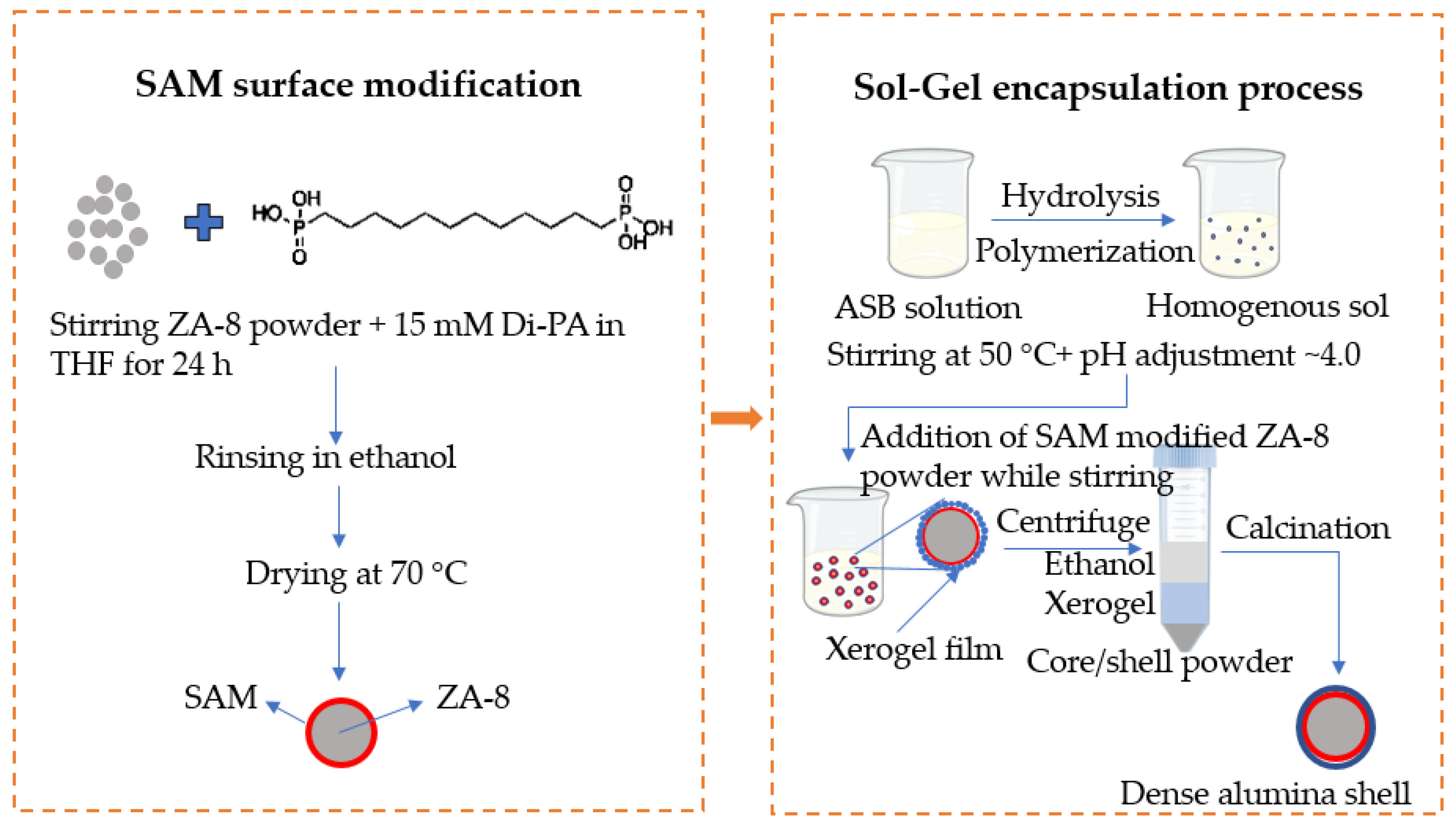
Figure 2.
Volume-weighted particle size distribution (PSD) (a) and sphericity distribution (b) of the as-atomized ZA-8 powder, as measured by DIA.
Figure 2.
Volume-weighted particle size distribution (PSD) (a) and sphericity distribution (b) of the as-atomized ZA-8 powder, as measured by DIA.
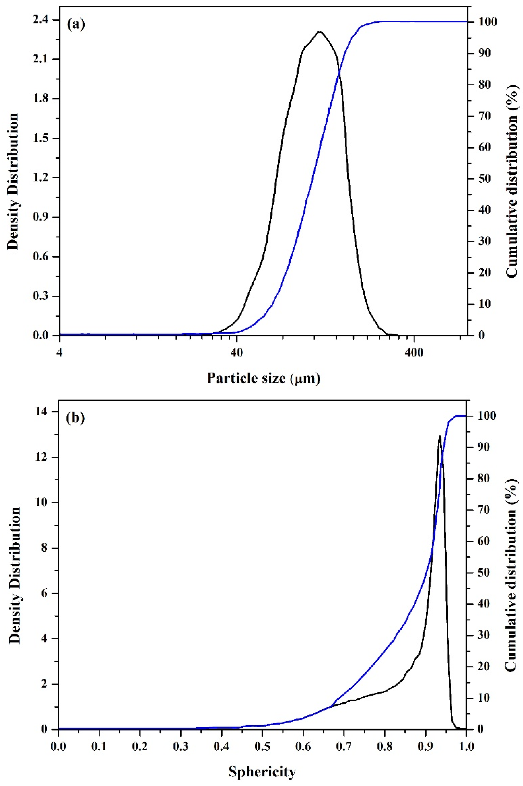
Figure 3.
A DI water drop on a SAM-modified powder bed. A hydrophobic surface is evident.
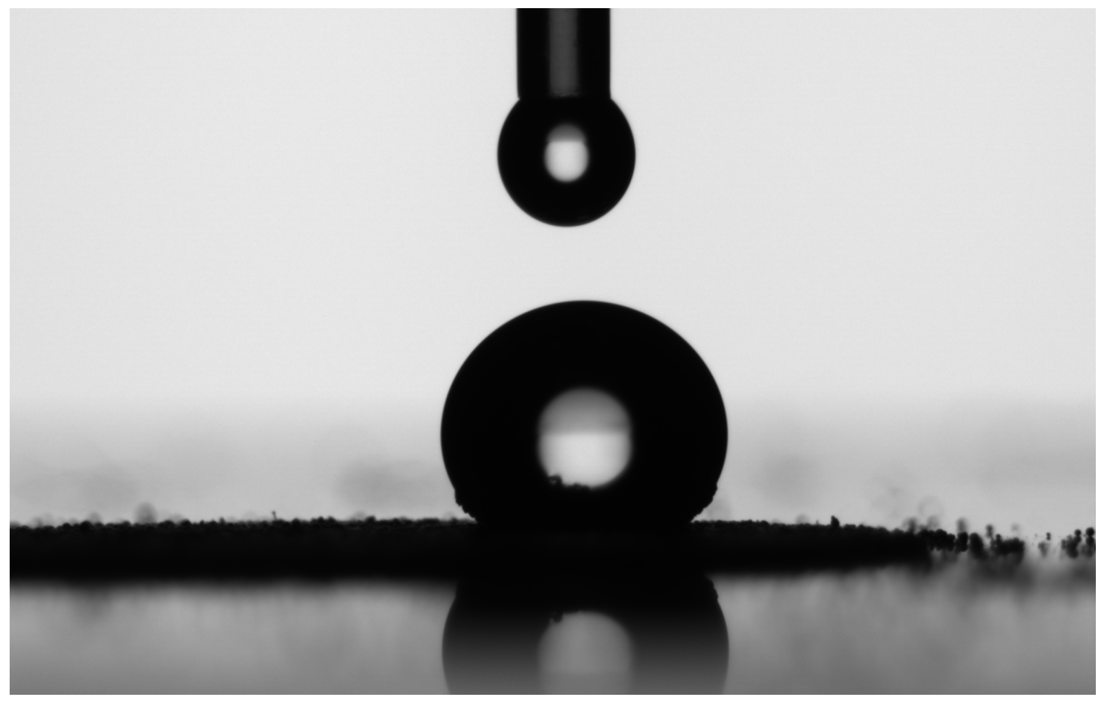
Figure 4.
SEM images of the surface (a,b) and cross-section (c,d) of the as-atomized ZA-8 powder. (a,c) Everhart–Thornley secondary electrons detector (ETD), (b,d) solid-state backscattered electrons detector (SSD).
Figure 4.
SEM images of the surface (a,b) and cross-section (c,d) of the as-atomized ZA-8 powder. (a,c) Everhart–Thornley secondary electrons detector (ETD), (b,d) solid-state backscattered electrons detector (SSD).
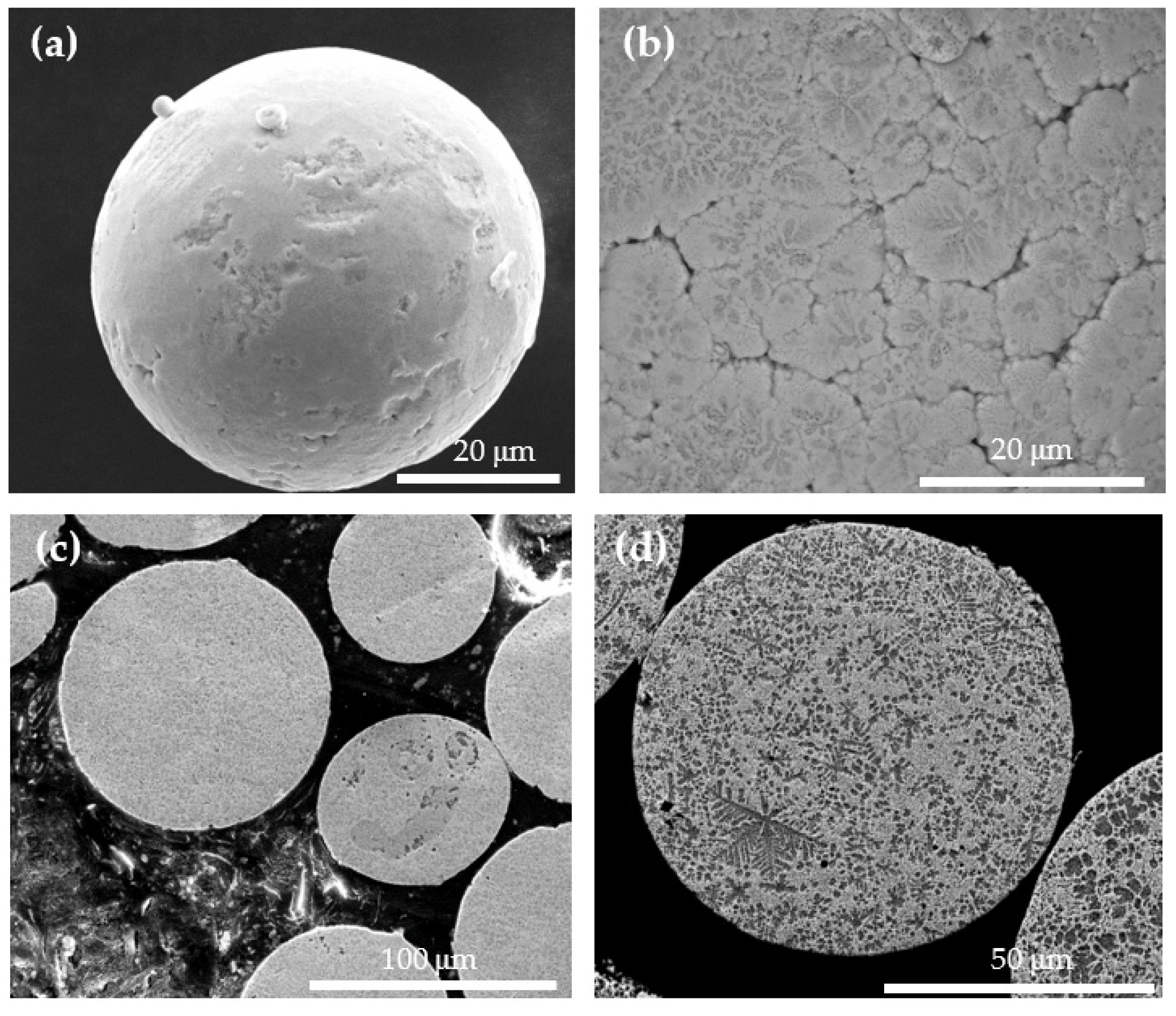
Figure 5.
SEM images of powder after the sol–gel and calcination processes. (a) A batch of powder after a scale-up process. (b) Surface morphology of a coated powder particle. (c) A particle that cracked during calcination due to volume expansion of the core alloy when it was melted. (d) Top view revealing the typical surface morphology of the alumina shell. (e) A side view of a cracked zone revealing the presence, conformity, uniformity, and thickness of the alumina shell. (f) Location of spot EDS analyses near a crack. See corresponding chemical composition in Table 3. (g) The microstructure at the cross-section of the powder particles, revealing that the core alloy was melted during calcination, yet remained encapsulated by the ceramic shell. All are secondary electron images, except (g), which is a backscattered electrons image.
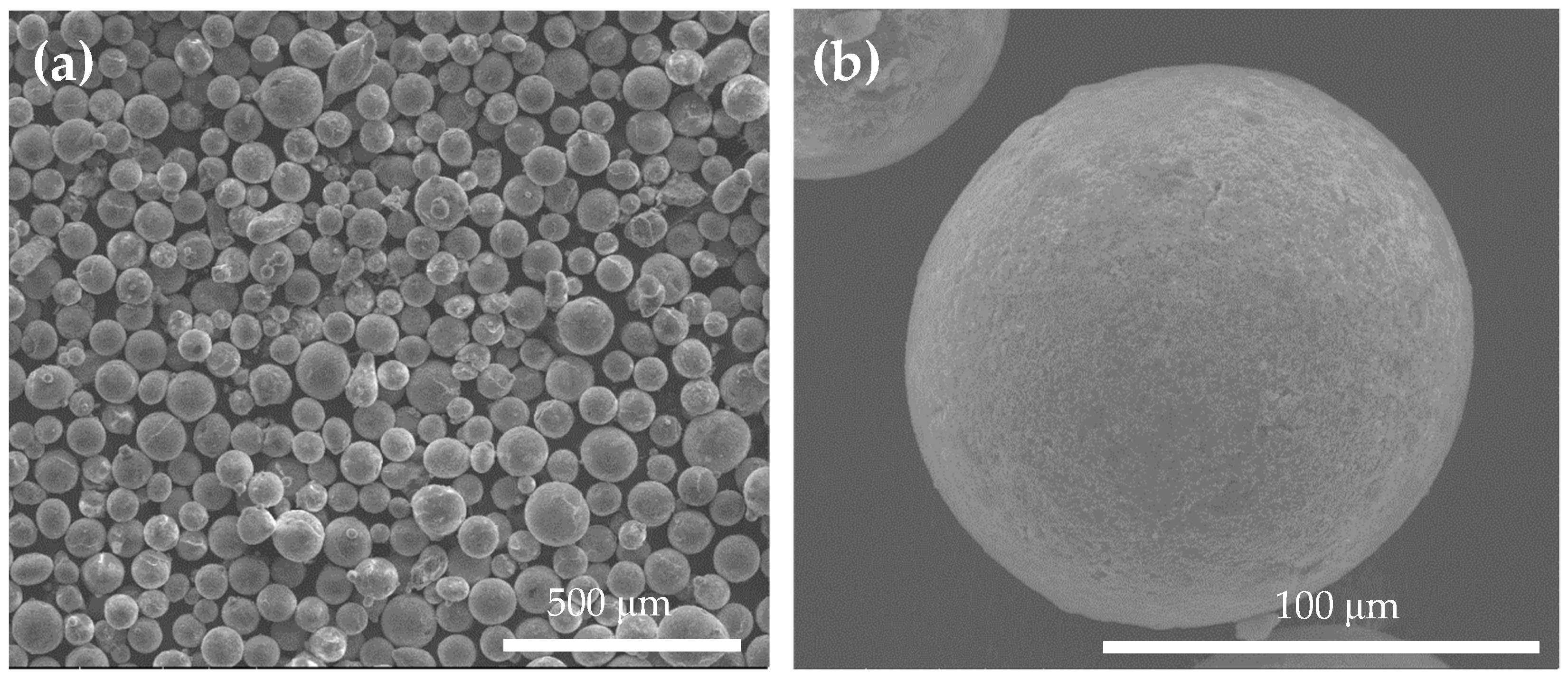

Figure 6.
(a) XPS Al 2p acquired without sputter-cleaning from the surfaces of as-atomized (red) and sol–gel-processed and air-calcined at 500 °C (green) powders. Peaks of the as-atomized and coated powders were shifted by −1.15 eV or −1.40 eV, respectively, and are positioned at 74.40 and 74.25 eV, respectively. (b) XPS Al 2p curve fitting (green line) and peak deconvolution (blue and magenta lines). The Al 2p spectrum seems to represent a mixture of 70.45% boehmite (magenta line) and 29.55% γ-alumina (blue line).
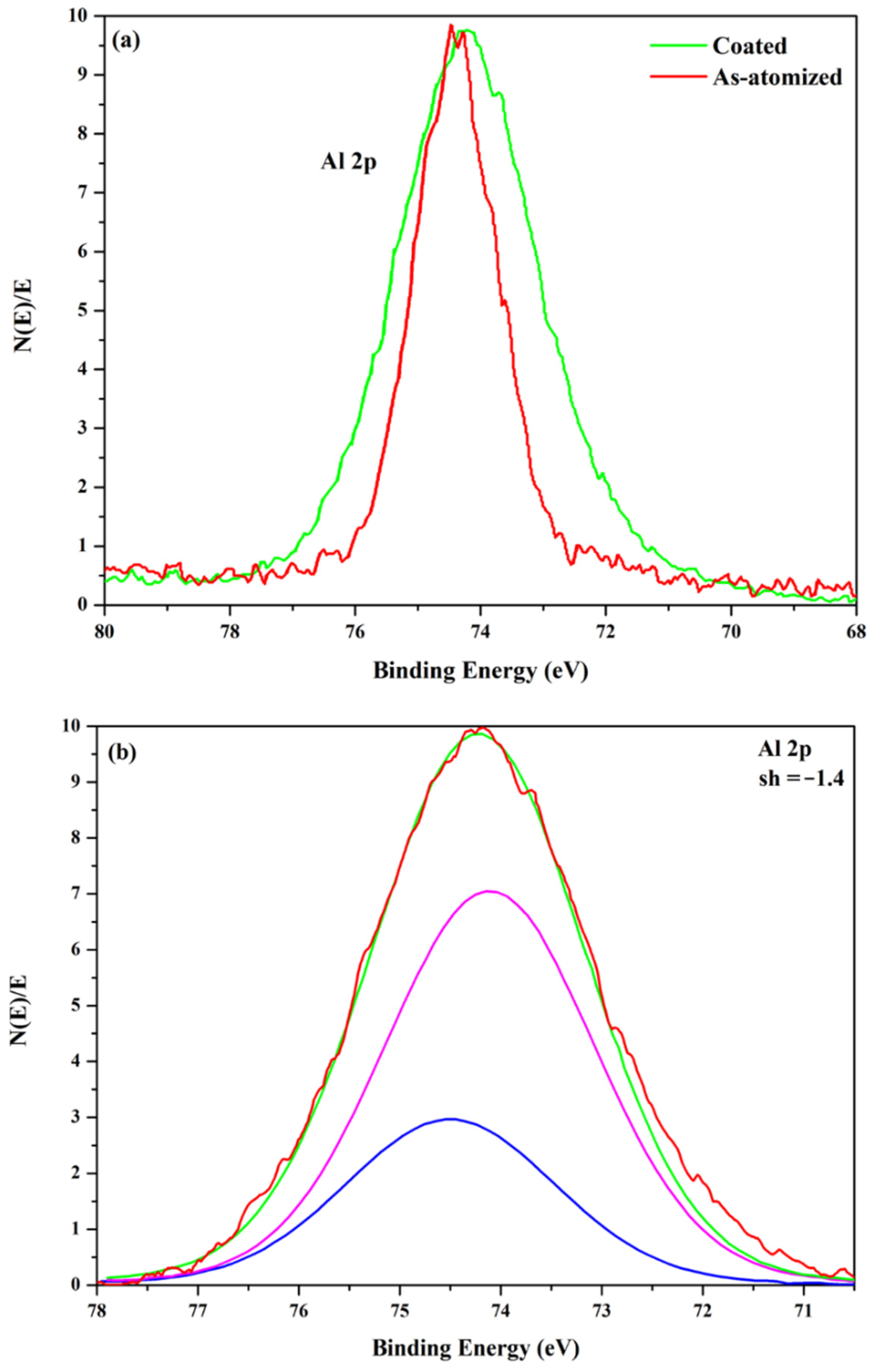
Figure 7.
SEM micrographs of ZA-8 powder particles after thermal stability tests in an air-atmosphere furnace at 600 °C for 1 h. (a,b) As-atomized powder. Aggregation, core leakage, and particle distortion are evident. (c–e) A powder pre-treated by two sol–gel cycles, followed by calcination. No aggregation is evident (c), although some particles have surface cavities (d) or are sintered to one another (e).

Table 1.
Mechanical and physical properties of the ZA-8 LMPP and an Al 5083-O matrix alloy [12].
Table 1.
Mechanical and physical properties of the ZA-8 LMPP and an Al 5083-O matrix alloy [12].
| Property | ZA-8 | Al 5083-O |
|---|---|---|
| Melting point (°C) | 375–404 | 571–637 |
| Tensile stress (MPa) | 220–425 | 248–283 |
| Yield strength (MPa) | 200–290 | 110–131 |
| Fatigue strength (MPa) | 50–105 | 64–67 |
| Young’s modulus (GPa) | 84–88 | 70–73.6 |
Table 2.
Volume-weighted particle size and sphericity of the as-atomized ZA-8 powder. The numbers in the left column represent the percentiles below which the PSD and sphericity have the 10%, 50% and 90% smallest values listed in the right two columns, respectively.
Table 2.
Volume-weighted particle size and sphericity of the as-atomized ZA-8 powder. The numbers in the left column represent the percentiles below which the PSD and sphericity have the 10%, 50% and 90% smallest values listed in the right two columns, respectively.
| Distribution Type | PSD | Sphericity |
|---|---|---|
| d10 (µm) | 63.57 | 0.69 |
| d50 (µm) | 106.75 | 0.90 |
| d90 (µm) | 163.43 | 0.94 |
Table 3.
Local chemical composition (EDS, wt.%) at the five spots in Figure 5f.
Table 3.
Local chemical composition (EDS, wt.%) at the five spots in Figure 5f.
| Spectrum | Zn | Al | Cu | Mg | O | C |
|---|---|---|---|---|---|---|
| 1 | 62.19 | 9.20 | 0.90 | 0.90 | 20.18 | 6.64 |
| 2 | 52.63 | 11.64 | 1.95 | 1.01 | 26.55 | 6.21 |
| 3 | 68.43 | 7.76 | 0.86 | - | 18.52 | 4.43 |
| 4 | 85.43 | 2.64 | 1.23 | - | 5.51 | 5.19 |
| 5 | 72.23 | 15.81 | 1.08 | - | 4.93 | 5.95 |
Publisher’s Note: MDPI stays neutral with regard to jurisdictional claims in published maps and institutional affiliations. |
© 2021 by the authors. Licensee MDPI, Basel, Switzerland. This article is an open access article distributed under the terms and conditions of the Creative Commons Attribution (CC BY) license (https://creativecommons.org/licenses/by/4.0/).
Share and Cite
MDPI and ACS Style
Svetlizky, D.; Eliaz, N. Sol–Gel Encapsulation of ZnAl Alloy Powder with Alumina Shell. Coatings 2021, 11, 1389. https://doi.org/10.3390/coatings11111389
AMA Style
Svetlizky D, Eliaz N. Sol–Gel Encapsulation of ZnAl Alloy Powder with Alumina Shell. Coatings. 2021; 11(11):1389. https://doi.org/10.3390/coatings11111389
Chicago/Turabian StyleSvetlizky, David, and Noam Eliaz. 2021. "Sol–Gel Encapsulation of ZnAl Alloy Powder with Alumina Shell" Coatings 11, no. 11: 1389. https://doi.org/10.3390/coatings11111389
Note that from the first issue of 2016, this journal uses article numbers instead of page numbers. See further details here.