Article

FEM Research on Welding Thermal Deformation of Copper Alloy Sheet and Optimization of Welding Sequence

1
School of Mechanical Engineering, Jiangsu University of Science and Technology, Zhenjiang 212100, China
2
Jiangsu Institute of Automation, Lianyungang 222006, China
*
Author to whom correspondence should be addressed.
Coatings 2021, 11(11), 1287; https://doi.org/10.3390/coatings11111287
Submission received: 8 September 2021 / Revised: 15 October 2021 / Accepted: 19 October 2021 / Published: 23 October 2021

Abstract

:
To reduce the residual stress and deformation of the copper alloy sheet after welding, and improve the welding quality of the copper alloy sheet, the finite element method (FEM) research on welding thermal deformation and welding sequence optimization was carried out. First, a finite element model of copper alloy sheet welding was established based on ANSYS, the mechanical property parameters of the model at high temperature were determined, and the thermal–structural coupling calculation was performed on the model. Then, the change trend and magnitude of the residual stress and deformation of the model after welding were analyzed. Finally, different welding sequence schemes were designed, and numerical simulation calculations were carried out. The results of the welding sequence solution show that the change trend of the residual stress after welding of the base metal under different welding sequences is basically the same; repeated heating of the base metal at the same position causes large residual stress; the weldment vertical plate is subjected to opposing forces in the x-axis and y-axis directions at the same time. Among four welding schemes, the welding scheme that alternately welds symmetrically from the start and end positions of the weld seam to the middle position of the plate causes the least welding deformation. Compared with the other three schemes, its deformation reduces by 26.6%, 18.3%, and 19.4%, respectively.

1. Introduction

Copper alloys are widely used in the manufacture of propellers, seawater piping systems, pump valves, and other structural parts in shipbuilding because of their good seawater corrosion resistance. However, the high temperature during welding will cause expansion and extrusion inside the material, which will cause defects such as deformation and residual stress of the weldment after it is completely cooled [1]. A large number of studies have shown that defects such as welding deformation are affected by the welding process but are also directly related to the welding sequence. How to reasonably arrange the welding sequence to control the welding deformation [2] has become the research focus of experts at home and abroad. Bi et al. [3] carried out numerical simulations on the welding deformation of the cascade with a crown partition. The simulation results show that the welding deformation of the structure is mainly due to the transverse and longitudinal shrinkage of the weld. By comparing the simulation results of two different welding sequences, it can be seen that the deformation generated by welding in the reverse direction is smaller than that in the forward direction. Shen et al. [4] studied the influence of welding sequence on the residual stress generated by butt welding of AH36 marine high-strength steel. The simulation results of four different welding sequences show that the distribution law of the initial stress and the final stress remain close. Sui et al. [5] constructed a welding sequence optimization model for a sulfur hexafluoride gas tank and carried out a numerical calculation for a single weld. The calculation results show that the top-down welding scheme can reduce welding deformation by 12.4%. Liu et al. [6] carried out an optimization study on the welding deformation of the luxury cruise liner’s segmented thin plate. They choose different welding sequences to control the deformation of the key sections of the deck. Existing researches on the optimization of welding sequence for different weldments are carried out around specific materials and structures, and there are few research studies on the optimization of curvilinear welding of copper alloy materials. However, there are a large number of curved welds in actual ship construction. Compared with straight welds, curved welds have more complicated changes in the internal force of the material during welding [7]. Additionally, the physical and mechanical properties of metal materials will change with temperature changes during welding, and different mechanical property parameters will cause significant differences in residual stress and post-welding deformation [8]. In this paper, the optimization of the welding sequence of copper alloy materials widely used in shipbuilding is studied. First, the finite element model of the welded structure was established, and the thermal-structural coupling calculation was performed on the model; then, the magnitude and change trend of the residual stress and deformation of the model after welding were analyzed; next different welding sequence schemes were designed, and numerical simulation calculations were carried out; finally, the welding deformation trends and laws of the curved weld structure were summarized according to the analysis results, which play a guiding role in the actual production of copper alloy sheet curved welds.

2. Model Development and Meshing of Welded Structure

2.1. Material Chemical Composition and Its Mechanical Property Parameters

Copper alloys are commonly used in the propellers and series of seawater pipes of commercial ships. The base material used in this paper was ZQAl12-8-3-2 copper alloy. The main chemical composition of ZQAl12-8-3-2 copper alloy is shown in Table 1 [9].
Copper has high thermal conductivity, and its mechanical properties change nonlinearly with temperature during welding. Therefore, physical performance parameters such as material density, thermal conductivity, specific heat capacity, and elastic modulus need to be set to effectively change with temperature during simulation, which is the prerequisite for obtaining reliable calculation results in accordance with actual working conditions. The heat transfer inside the material is related to the density, thermal conductivity, and specific heat capacity of the material. In addition, the thermal load applied to the weldment material exerts a force on the base material itself. The accurate acquisition of the material’s elastic modulus, linear expansion coefficient, and Poisson’s ratio parameters is a necessary condition for material thermal stress analysis [10]. The parameter settings of material mechanical properties are shown in Table 2 [11,12,13,14]. The Poisson’s ratio μ was set to 0.337 in this paper because its variation range was small, and its influence on the calculation results was negligible.

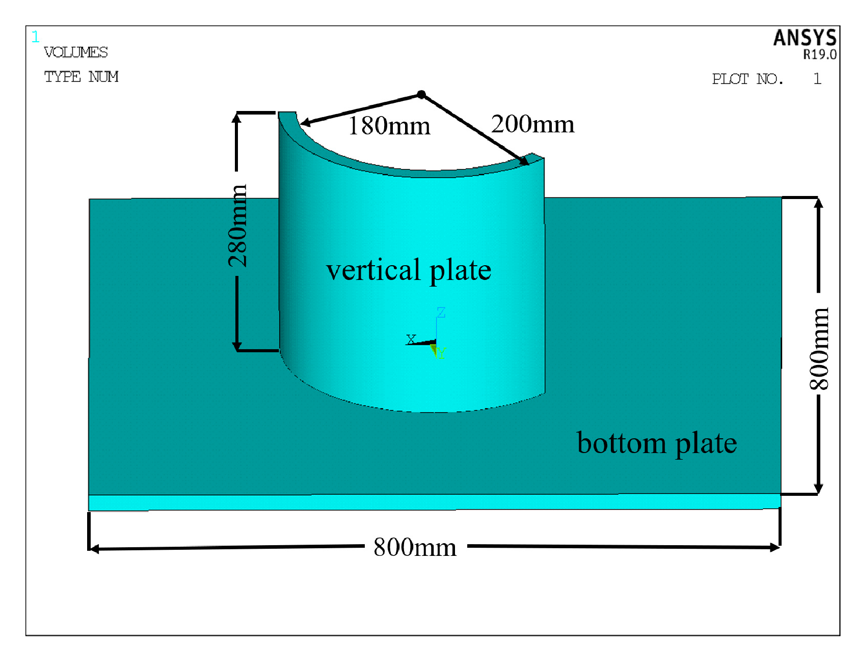
2.2. The Development of Three-Dimensional Structure Model of Welding Object

Compared with straight welds, curved welds are prone to non-convergence problems when performing thermal–structural coupling calculations due to their complex and irregular structure. Figure 1 shows a relatively common arc welded joint in ship construction, which connects the cylindrical shell vertical plates and the flat plates through corner joints. Due to the continuous change in the heat source angle during welding, welding defects such as cracks and pits are prone to appear on the vertical plate after welding. Figure 2 shows the three-dimensional model of the structure in Figure 1, and the dimensions are also shown. The thickness of the flat plate is 20 mm, the outer radius of the vertical plate is 200 mm, and the inner radius of the vertical plate is 180 mm. A vertical plate was fixed on the bottom plate by non-melting electrode gas-shielded welding, and only a single-pass weld was welded on the outside of the vertical plate by means of fillet welding.

2.3. The Development of Finite Element Model of Welding Object

In order to obtain the residual stress and deformation results of the base metal after welding, it is first necessary to divide the three-dimensional structure model into a finite element model [15]. The meshing of the model selected solid 70 for a multi-physics coupling solution. Considering the particularity of the curved weld, the four arc edges of the weld body were first divided into equal parts; then, the mesh was divided by sweeping to ensure that each element on the weld was uniform in size, and the result is shown in Figure 3. A uniform grid can realize the “birth-death” operation of the unit to simulate the generation of welds during welding. Considering that the arc-shaped vertical plate is a key area in welding deformation analysis, the mesh size was divided into 10 mm to ensure the accuracy of the solution. As the base plate had a large volume, and too-small mesh size would reduce the efficiency of the solution, the mesh was divided into 20 mm size. As the vertical plate and the bottom plate were directly connected to the weld elements, the free meshing was uniformly used to ensure the node connectivity between the elements [16]. In addition, in actual working conditions, the weldments were fixed by fixtures during welding, and the fixtures limited the free expansion of the base metal when heated to a certain extent. Therefore, the movement and rotation of the bottom surface of the weldment, and the movement of the vertical plate in the vertical direction were restricted when the finite element model was developed.

2.4. Setting of Welding Process Parameters

For the welding of marine copper alloy materials, the welding method was non-melting electrode gas-shielded welding, and the shielding gas was helium. In this paper, the heat generation rate of the welding unit was calculated by Formula (1) [17], so as to simulate the influence of the non-melting gas-shielded welding heat source on the base metal. In order to make the calculation results in line with the actual situation, the welding voltage was 240 A, and the welding current was 25 V. In addition, during the simulation calculation, the welding speed was set to 3.5 mm/s, and the base metal temperature was set to 50 °C before the transient thermal analysis.
H g e n = k U I u t A
where Hgen is the body heat rate; k is the thermal efficiency of the welding heat source; U is the welding voltage; I is the welding current; u is the welding speed; t is the time of each load step; A is the cross-sectional area of the weld.

3. Numerical Calculation and Analysis

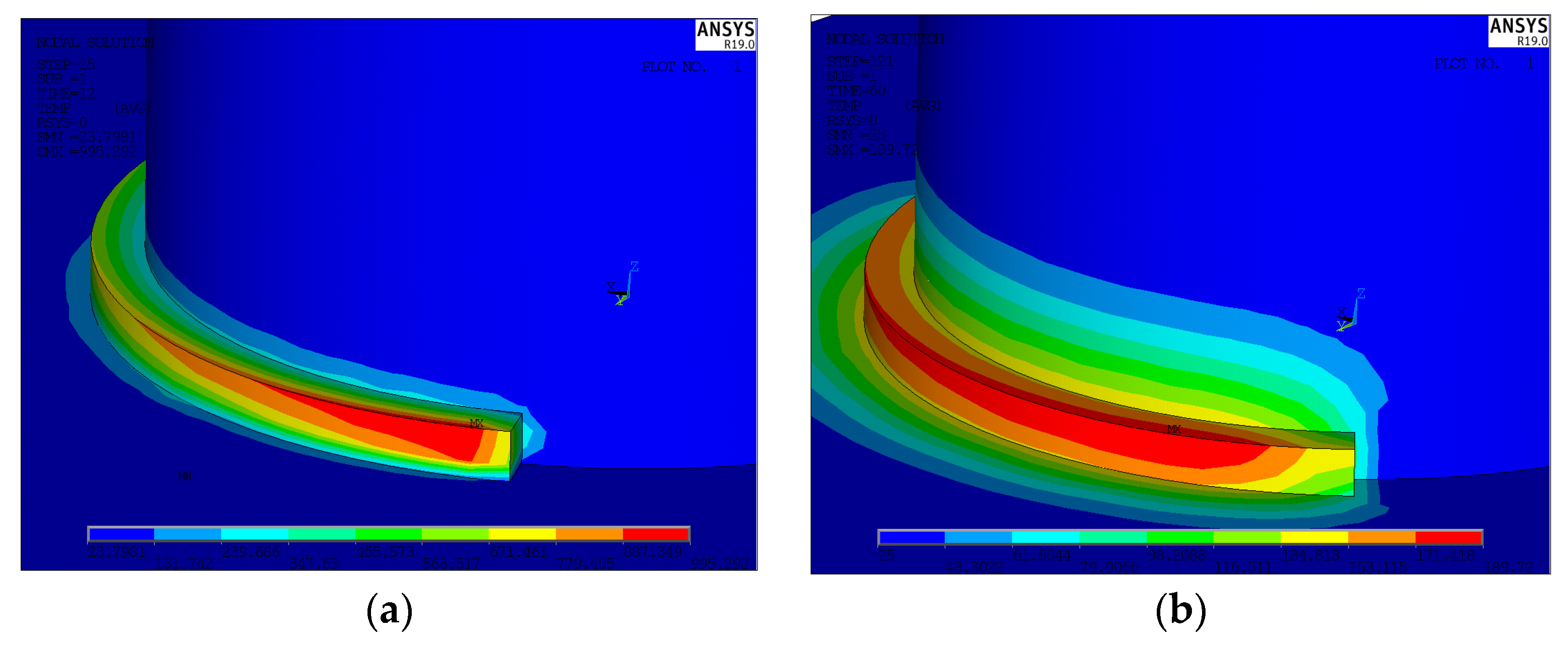
3.1. Analysis of Welding Temperature Field of Base Metal

The thermal load imposed by the temperature field on the base metal element is a sufficient condition for the calculation of the residual stress field [18]. Figure 4 shows the temperature field of the base metal at a certain moment during the welding process. The welding seam unit is gradually generated during the movement of the heat source. At this time, the heat has not diffused to the area near the welding seam, as shown in Figure 4a. The temperature of the welding unit is relatively high, and with the accumulation of time steps, heat will gradually be transferred to the base metal unit, as shown in Figure 4b. The temperature gradient of the base metal in the vicinity of the welding seam changes greatly, and the temperature gradually decreases with the increase in the distance from the welding seam. It can be seen that the heat transfer of the base metal is consistent with the actual working conditions.

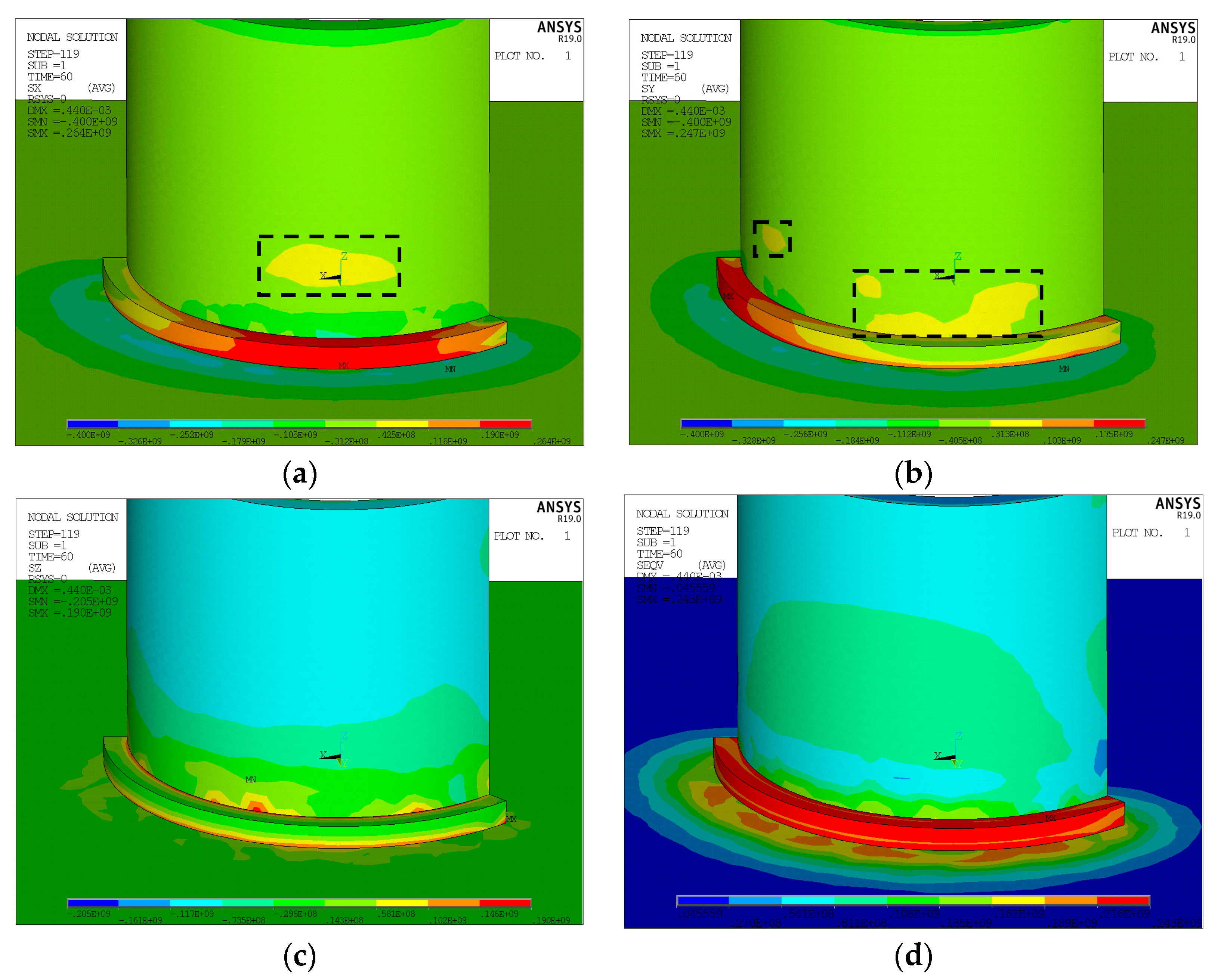
3.2. Analysis of Residual Stress Field of Base Metal Welding

Figure 5 shows the residual stress cloud diagram of the weldment after welding. From Figure 5, it can be seen that the residual stress in all directions along the weld seam and its vicinity is relatively large. After welding, the area near the bottom of the vertical plate is simultaneously subjected to the residual compressive stress pointing to the circle center and the reverse residual tensile stress, as shown in Figure 5a. The force on the area far from the bottom and the area near the bottom is the same, as shown in Figure 5b. The bottom of the vertical plate receives a force perpendicular to the bottom plate and directed to the bottom plate, as well as a reverse force, as shown in Figure 5c. As the welding area increases, the force on the bottom of the vertical plate gradually decreases. Due to the special structure of the vertical slab, the variation of von Mises residual stress is more complicated than that of the bottom plate area, and the peak von Mises stress generated is smaller than that of the bottom plate, as shown in Figure 5d. This is mainly because the bottom plate is subject to more constraints.

3.3. Simulation Result Analysis

In order to understand the residual stress and deformation of the vertical plate after welding, ten nodes along the vertical direction of the vertical plate are selected, the point path in the vertical direction is determined by the midpoints of the upper and lower edges of the outer surface of the vertical plate, as shown in Figure 6, and the residual stress along the x-axis direction (Fx/MPa), residual stress along the y-axis direction (Fy/MPa), residual stress along the z-axis direction (Fz/MPa), von Mises stress (Fvon/MPa), and resultant displacement (DOF/mm) of each node are obtained. The average values of the calculation results are shown in Table 3. From the table, it can be seen that there are serious residual stresses and welding deformation defects on the vertical plate after welding. The vertical slab is subjected to large residual stresses perpendicular to the bottom plate and von Mises stress. The maximum von Mises stress reaches 85 MPa; the residual stress on the vertical plate parallel to the bottom plate is relatively small, and the minimum average value is only 3.7 MPa.

4. Welding Sequence Optimization

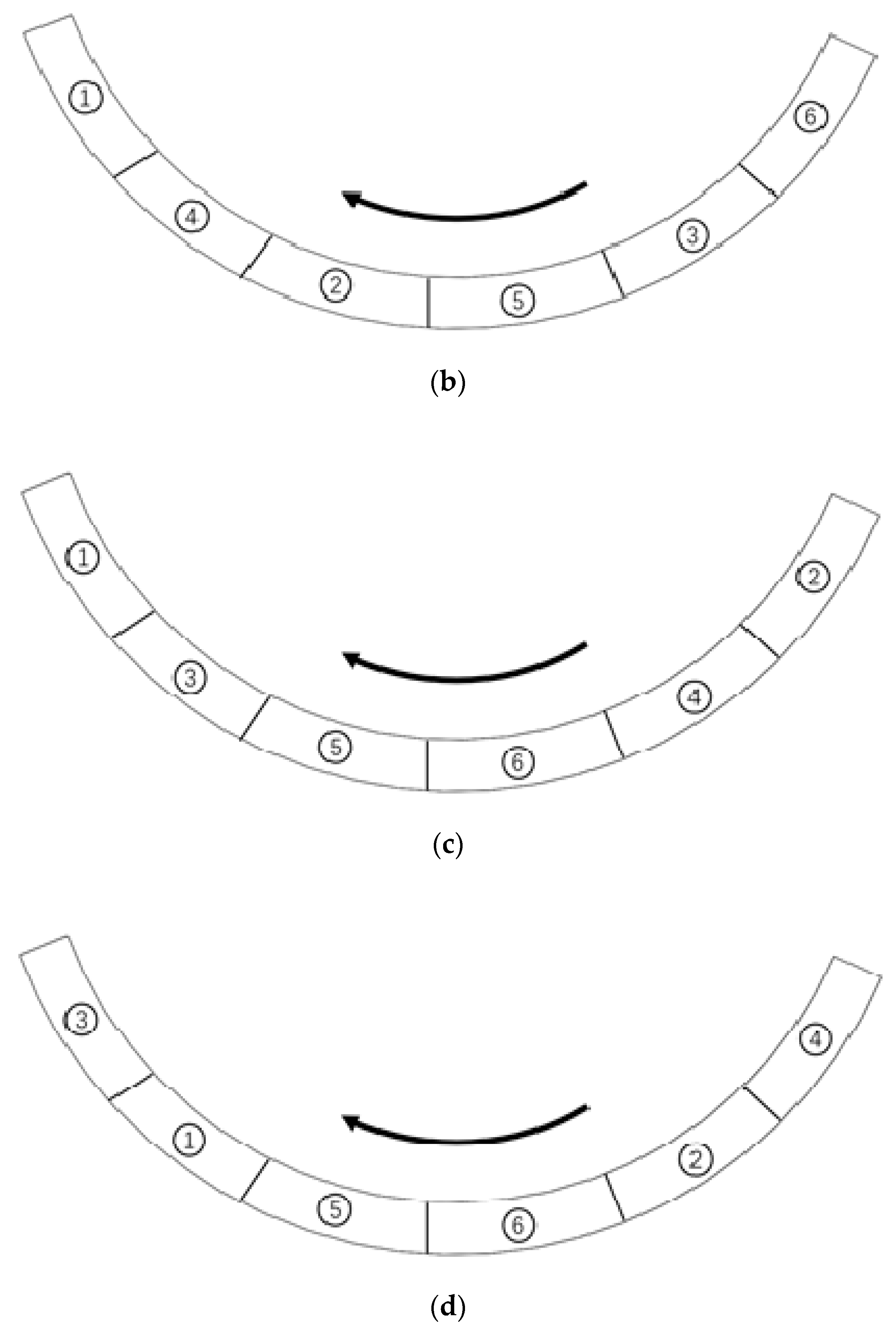
4.1. Determination of Optimization Scheme for Welding Sequence

In order to ensure the typicality of the optimization process and guarantee optimization efficiency, the curved weld was divided into six segments, and six welds needed to be welded during the entire welding process. If the influence of welding direction is not considered, there were a total of 6! different welding schemes. As simulation calculations and experiments are very costly or even difficult to implement, four relatively reasonable welding sequence schemes were first proposed, and the welding direction is shown in Figure 7, in which the numbers represent the order of sequence. Scheme 1 in Figure 7a is a conventional welding scheme, that is, the heat source moves from the starting position of the weld to the ending position of the weld without any sequential changes.

4.2. Optimization and Analysis

Figure 8 shows the residual stress comparison of the above four different welding schemes, the node selection location is explained in Section 3.3. From Figure 8, it can be seen that different welding sequences have little effect on the magnitude and change trend of welding residual stress. The maximum stress of the base metal after welding is maintained at about 150 MPa. The residual stress along the x-axis on the vertical plate mainly points to the center of the circle, as shown in Figure 8a. Near the welding position, the magnitude of the residual stress changes drastically, and it decreases rapidly at first and then slowly increases. The residual stress on the base metal that is farther from the weld has a smaller variation. As the heat source moves along the weld curve, the change trend of the residual stress along the y-axis and the x-axis on the vertical plate is not the same, and the residual stress along the y-axis is relatively small, with a peak value of only 20 MPa, as shown in Figure 8b. At positions close to and away from the weld, the base metal bears the force directed from the outside to the center of the circle; at the location between the bottom and the top, the base metal bears the force directed from the center of the circle to the outside. The residual stress in the z-axis direction is mainly directed toward the bottom plate, as shown in Figure 8c, which indicates that the inside of the vertical plate bears the tensile force from the bottom welding position. The stress on the bottom and top of the vertical plate is relatively small, and the stress peak appears in the middle area of the shell plate and is about 85 MPa. After welding, the base metal bears a large von Mises residual stress, with a peak value of 127 MPa, as shown in Figure 8d. The stress near the weld seam also changed drastically. In the location within 47 mm from the weld seam, the Mises residual stress quickly drops to about 80 MPa. In the location between 47 mm and 95 mm from the weld, the Mises stress suddenly rises, and after reaching a peak of about 100 MPa, the Mises stress gradually decreases as the distance from the weld increases.
The deformation of the vertical plate after welding is relatively large, but the bottom plate does not appear obvious bending deformation under the gravity of itself and the vertical plate. In total, 10 nodes were selected from the vertical plate along the vertical direction and the welding direction to define the path. The point path in the horizontal direction was determined by the midpoints of the left and right edges of the outer surface of the vertical plate, as shown in Figure 9. The point path in the vertical direction was determined by the midpoints of the upper and lower edges of the outer surface of the vertical plate, as shown in Figure 10. The size and change trend of welding deformation were analyzed. Figure 11 shows the comparison of the welding deformations of four schemes for the same position welding. From Figure 11, it can be seen that the deformation changes caused by the four welding sequences after welding are the same, but the deformation at the root of the vertical plate is the most severe. The farther the location is from the root, the smaller is the deformation, and the deformation shows a decreasing trend. The deformation direction of the large deformation area is from the center of the circle to the outside, and the deformation direction away from the welding seam is from the outside to the center of the circle. This is mainly due to the thermal expansion of the bottom of the vertical plate during welding. In addition, there is a temperature difference between the weld and its nearby location, the deformed area is constrained by the location away from the heat source, and plastic deformation occurs inside the base metal when the temperature reaches the yield limit of the material. As the heat source moves, the first welded part shrinks due to the decrease in temperature, but at the same time, it bears tensile stress due to the constraints of the nearby materials, and finally, the base material is deformed under the action of this force. Through comparison, it can be seen that the deformation peak and overall deformation of the third scheme are smaller than those of the other three schemes, and the post-weld deformation of the vertical plate along the welding seam direction is not drastic. However, the deformation peak caused by the conventional welding scheme 1, which welds from the start position to the end without changing the order, is the largest. The staggered welding scheme 2 causes the deformation trend of the base material along the welding seam direction to be unstable. This is mainly because the base material is repeatedly heated at the same position, and then the inside of the material is repeatedly subjected to different magnitudes of forces. Although the peak value of welding deformation caused by scheme 4 is higher than scheme 3, the overall deformation is better than scheme 1 and scheme 2.
Table 4 shows the average values of residual stresses and welding deformations on selected nodes for four different welding schemes. From Table 4, it can be seen that different welding sequences will affect the residual stress and welding deformation of the weldment after welding. The four welding schemes have their own advantages and disadvantages for the impact of the residual stress, but the difference is not considerable. Along the x-axis, the residual stress caused by scheme 2 is the smallest, and the residual stress caused by scheme 4 is the largest. Along the y-axis direction, the residual stress caused by scheme 1 is the smallest, and it is 0.6 MPa lower than the residual stress caused by scheme 2. Along the z-axis, the residual stress caused by scheme 4 is the largest, and it is 9.8 MPa higher than the residual stress caused by scheme 3. Among the four welding schemes, the welding deformation caused by scheme 3 is the smallest, and compared with scheme 1, scheme 2, and scheme 4, it is reduced by 26.6%, 18.3%, and 19.4%, respectively.
In this paper, numerical calculation and analysis were carried out for the curved welding-seam welding of copper alloy plates. Although the deformation and residual stress changes of the base metal after welding were obtained, there were still errors between the numerical simulation and the real welding conditions. Therefore, the next step of the research work is mainly to carry out welding experiments on the curved welds of copper alloy plates and compare the experimental results with numerical calculations to further verify and correct the conclusions of welding thermal deformation, so as to lay a solid foundation for improving the welding quality of curved welds on copper alloy sheets.

5. Conclusions

Defects such as residual stress and deformation caused by the welding of metal materials will reduce the welding rigidity, thus further affecting the load-bearing capacity of the structure. Focusing on copper alloy plate materials, based on the finite element model, research on thermal deformation of welded parts and optimization of welding sequence was carried out in this paper. Through numerical calculation and comparison, the following conclusions can be drawn:
(1)
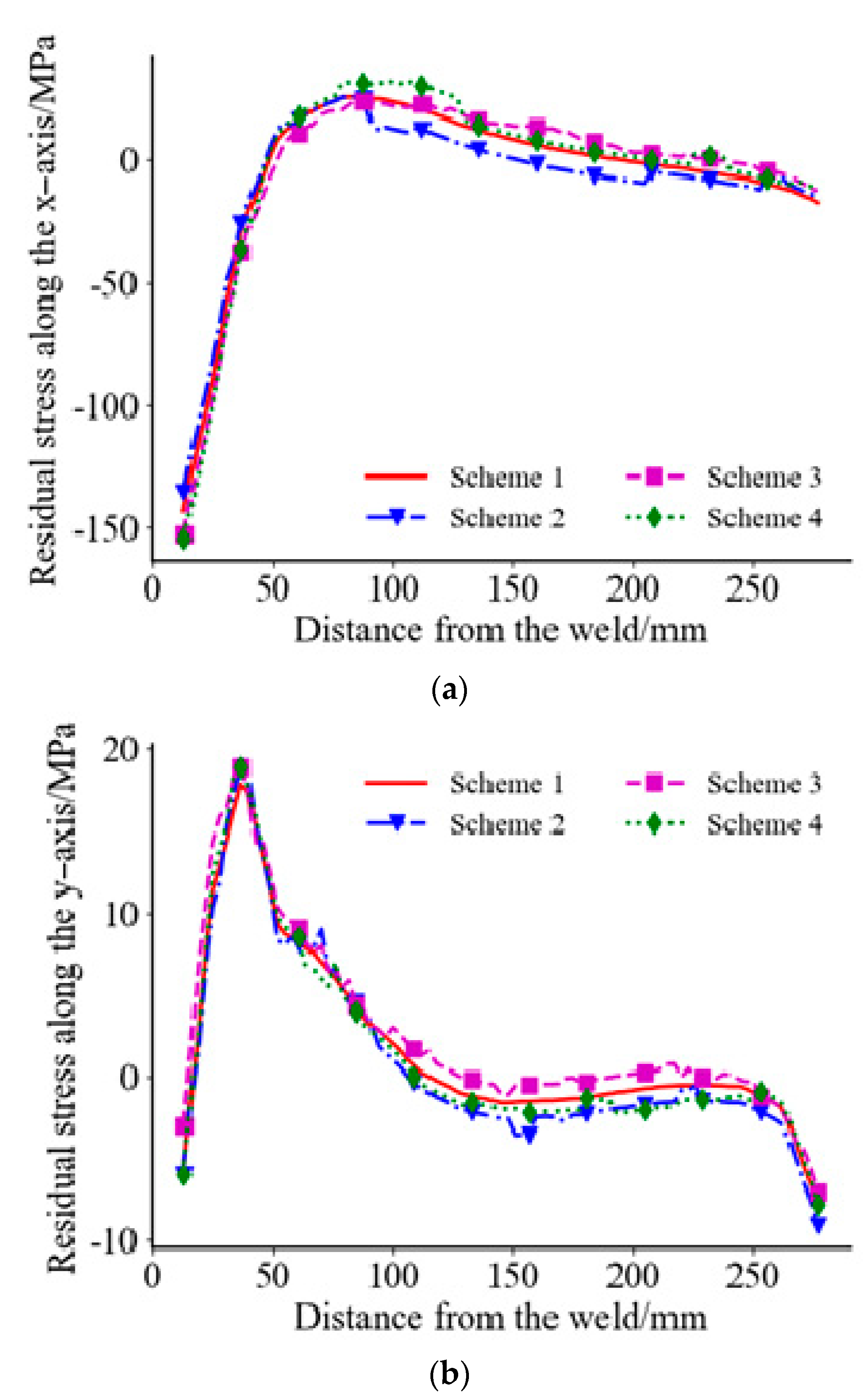
For curved fillet welding, the welded vertical plate bears a large tensile stress perpendicular to the weld and compressive stress, pointing in the direction of the center of the circle. Tensile stress and compressive stress exist on the vertical plate in different directions at the same time and are mainly concentrated on the base metal near the welded seam.
(2)
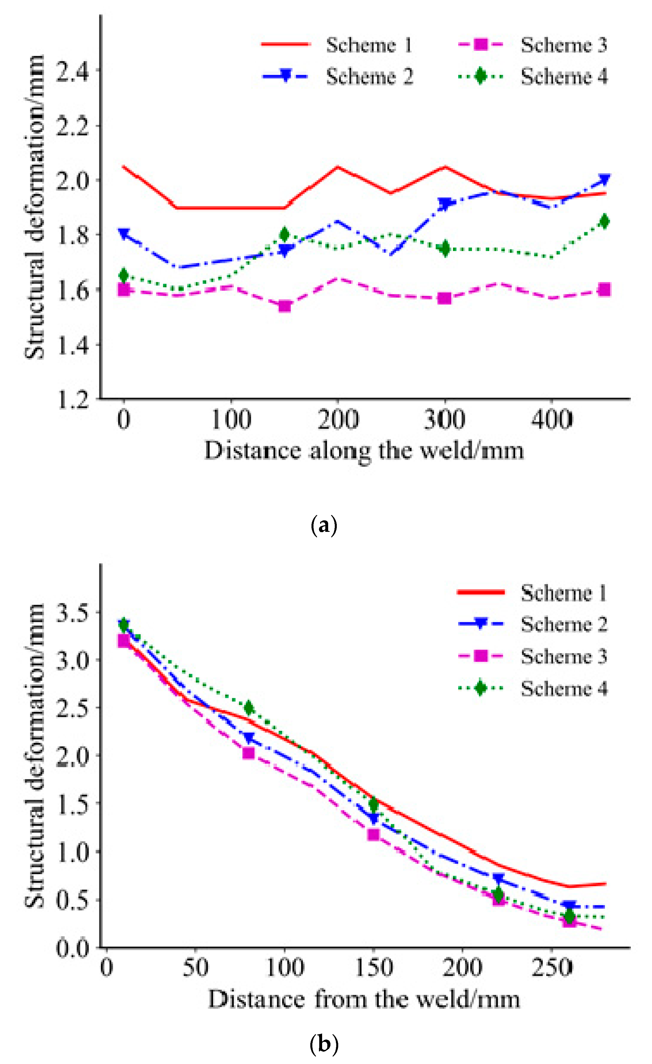
Through the calculation and comparison of four different welding sequence schemes, it can be found that although the magnitude and change trend of the residual stress of the base metal caused by different welding sequences are not much different, and the welding scheme that alternately welds symmetrically from the start and end positions of the weld seam to the middle position of the plate causes the least deformation.
(3)
When performing curved weld welding, repeated heating of the base metal at the same position should be avoided as much as possible; otherwise, it will cause greater residual stress in the base metal.

Author Contributions

Methodology, M.Y. and S.L.; validation, M.Y., H.S. and X.D.; writing—original draft preparation, S.L. and W.C.; writing—review and editing, S.L. and Y.G. All authors have read and agreed to the published version of the manuscript.

Funding

This research was funded by the High-Tech Ship Scientific Research Project from the Ministry of Industry and Information Technology ([2019]360).

Institutional Review Board Statement

Not applicable.

Informed Consent Statement

Not applicable.

Data Availability Statement

Not applicable.

Conflicts of Interest

The authors declare no conflict of interest.

References

  1. Li, Z.L.; Feng, G.G.; Deng, D.; Luo, Y. Investigating welding distortion of thin-plate stiffened panel steel structures by means of thermal elastic plastic finite element method. J. Mater. Eng. Perform. 2021, 23, 1–14. [Google Scholar]
  2. Romero-Hdz, J.; Saha, B.; Toledo-Ramirez, G.; Beltran-Bqz, D. Welding sequence optimization using artificial intelligence techniques, an Overview. Int. J. Eng. Sci. 2016, 3, 80–85. [Google Scholar]
  3. Bi, T.; Xiong, J.K.; Zhao, P.F.; Yang, l.; Zhang, H.T. Numerical simulation of welding deformation of diaphragm cascade. Weld. Technol. 2021, 50, 29–34. [Google Scholar]
  4. Shen, Y.; Li, M.M.; Zhang, B.S.; Luo, G.E. Study on the effect of welding sequence on welding residual stress and its release of AH36 marine high-strength steel. Electr. Weld. Mach. 2020, 50, 15–21. [Google Scholar]
  5. Sui, X.H.; Chen, H.Z.; Liang, Z.H.; Zhao, C.Z.; Liu, X.Y. Optimization of welding sequence of sulfur hexafluoride inflatable cabinet based on numerical. Sci. Tech. Engrg. 2019, 19, 117–122. [Google Scholar]
  6. Liu, Y.; Li, Y.; Liu, H. Solution for welding deformation of segment sheet for luxury cruise liner. Weld. Technol. 2020, 49, 119–121. [Google Scholar]
  7. Zhang, Y.Y.; Zheng, C.H.; Gao, T.T.; Mao, Y.; Jiang, Y.; Xu, M. Microstructure and mechanical properties of titanium alloy plane curve butt welded joints. Hot Work. Technol. 2020, 49, 150–152. [Google Scholar]
  8. Guo, Z.F.; Bai, R.X.; Lei, Z.K.; Jiang, H.; Zou, J.C.; Yan, C. Experimental and numerical investigation on ultimate strength of laser-welded stiffened plates considering welding deformation and residual stresses. Ocean Eng. 2021, 234, 109239. [Google Scholar] [CrossRef]
  9. Zou, J.S.; Luo, X.F.; Ji, Z.C.; Yan, K. Study on Welding Properties of Copper Alloy for Warship Propeller. J. Jiangsu Univ. Sci. Technol. 2006, 3, 81–84. [Google Scholar]
  10. Schnmaier, H.; Krein, R.; Schmitz-Niederau, M.; Schnitzer, R. Influence of the heat input on the dendritic solidification structure and the mechanical properties of 2.25Cr-1Mo-0.25V submerged-arc weld metal. J. Mater. Eng. Perform. 2021, 6, 1–14. [Google Scholar] [CrossRef]
  11. Xiao, Q.K.; Zhu, Z.Q.; Li, M.F. Ultrasonic welding and numerical simulation of copper. Weld. Technol. 2019, 48, 15–19. [Google Scholar]
  12. Peng, P.J.; Yu, J.; Liu, C.; Xie, J.; Yang, Z.W. High frequency electromagnetic induction welding of copper steel based on ANSYS magnetic field and thermal field simulation. Electr. Weld. Mach. 2018, 48, 92–96. [Google Scholar]
  13. Singh, R.; Singh, S.; Kanigalpula, P.K.C.; Saini, J.S. Electron beam welding of precipitation hardened CuCrZr alloy: Modeling and experimentation. Trans. Nonferrous Met. Soc. China 2020, 30, 2156–2169. [Google Scholar] [CrossRef]
  14. Ma, H.B. ANSYS Welding, 3D Printing, Laser Repair Topics. 2017. Available online: http://edu.yanfabu.com/course/629 (accessed on 10 May 2021).
  15. Zhao, W.; Jiang, W.; Zhang, H.; Han, B.; Gao, Q. 3D finite element analysis and optimization of welding residual stress in the girth joints of X80 steel pipeline. J. Manuf. Process. 2021, 66, 166–178. [Google Scholar] [CrossRef]
  16. Ordieres, J.; Rodríguez, E.; Bay’on, A.; Caixas, J.; Barbensi, A.; Martín, C. Determination of the influence of clamping on welding distortion applied to PS2 mock-up using finite element simulations. Fusion Eng. Des. 2021, 166, 112327. [Google Scholar] [CrossRef]
  17. Hamahmy, M.; Deiab, I. Review and analysis of heat source models for additive manufacturing. Int. J. Adv. Manuf. Tech. 2020, 106, 1223–1238. [Google Scholar] [CrossRef]
  18. Wu, Z.B.; Zhou, K.F.; Guo, L.L.; Zhao, H.C.; Deng, Y.T.; Zhang, W.C.; Zhen, W.X. Influence of welding sequence on residual stress and deformation of corner joint. Hot Work. Technol. 2021, 50, 150–154. [Google Scholar]
Figure 1. Arc-welded joint.
Coatings 11 01287 g001
Figure 2. Three-dimensional model of weldment.
Coatings 11 01287 g002
Figure 3. Meshing of finite element model for weldment.
Coatings 11 01287 g003
Figure 4. Welding temperature field at a certain moment: (a) temperature field at step 25; (b) temperature field at step 121.
Coatings 11 01287 g004
Figure 5. Welding residual stress cloud diagram: (a) residual stress along the x-axis; (b) residual stress along the y axis; (c) residual stress along the z-axis; (d) von Mises stress.
Coatings 11 01287 g005
Figure 6. Schematic diagram of node selection location.
Coatings 11 01287 g006
Figure 7. Schematic diagram of welding scheme: (a) scheme 1; (b) scheme 2; (c) scheme 3; (d) scheme 4.
Coatings 11 01287 g007aCoatings 11 01287 g007b
Figure 8. Comparison of residual stress in the vertical direction of the vertical plate: (a) residual stress along the x-axis; (b) residual stress along the y-axis; (c) residual stress along the z-axis; (d) von Mises residual stress.
Coatings 11 01287 g008aCoatings 11 01287 g008b
Figure 9. Schematic diagram of node selection of vertical plate along the welding direction.
Coatings 11 01287 g009
Figure 10. Schematic diagram of node selection along the vertical of the riser.
Coatings 11 01287 g010
Figure 11. Comparison of deformation in parallel and perpendicular weld directions: (a) structural deformation in the direction of the weld; (b) structural deformation perpendicular to the welding direction.
Coatings 11 01287 g011
Table 1. The chemical composition of ZQAl12-8-3-2 copper alloy.
MaterialCuMnAlZnFeNi
ZQAl12-8-3-2Others11.5–14%7.0–8.5%≤0.3%2.5–4.0%1.8–2.5%
Table 2. Changes in the mechanical properties of base material at different temperatures.
T (°C)25100200300400500600700
ρ79907973794279137880784078007762
λ36.53737.53838.639.239.640.5
c402.4412420430446455464473
E1.0681.0601.0140.980.850.750.680.65
a1.51.51.522222
T (°C)800850915950108312001500
ρ7710767475497275722570456788
λ415080100200350500
c482514527530530530530
E0.480.30.20.20.20.20.2
a3333333
ρ is the base material density (kg/m3), λ is the thermal conductivity (W/(m × K)), c is the specific heat capacity (J/kg/K), E is the elastic modulus (1011 Pa), a is the linear expansion coefficient (10−5 K), T is celsius (°C).
Table 3. Residual stress and deformation of base metal.
ParametersFxFyFzFvonDOF
Average value19.33.776.685.01.58
Table 4. Residual stress and deformation after welding of the four schemes.
ParametersFxFyFzFvonDOF
Scheme 1 19.33.776.685.01.58
Scheme 2 17.34.376.586.91.42
Scheme 3 20.63.875.985.71.16
Scheme 4 22.04.085.784.11.44
Publisher’s Note: MDPI stays neutral with regard to jurisdictional claims in published maps and institutional affiliations.

