
Preparation of Wear-Resistant Coating on Ti6Al4V Alloy by Cold Spraying and Plasma Electrolytic Oxidation


1
School of Metallurgical Engineering, Xi’an University of Architecture and Technology, Xi’an 710055, China
2
Shaanxi Engineering Research Center of Metallurgical, Xi’an University of Architecture and Technology, Xi’an 710055, China
*
Author to whom correspondence should be addressed.
Coatings 2021, 11(11), 1288; https://doi.org/10.3390/coatings11111288
Submission received: 21 September 2021
/
Revised: 12 October 2021
/
Accepted: 19 October 2021
/
Published: 23 October 2021
(This article belongs to the Special Issue Advanced Surface Treatments for Wear Resistance)
Abstract
:In order to improve the wear resistance of Ti6Al4V alloy, the alloy was first coated with alumina-reinforced aluminum coating (CS-coating) by cold spraying, and then the alloy with CS-coating was processed by plasma electrolytic oxidation (PEO) under unipolar mode and soft sparking mode, respectively, to prepare wear-resistant PEO coatings. For comparison, Ti6Al4V alloy without CS-coating was also subjected to PEO treatment. The microstructure, phase composition, hardness, and wear resistance of the PEO coatings formed on Ti6Al4V alloy with and without CS-coating were investigated. The results revealed that PEO coatings formed on Ti6Al4V alloy with CS-coating under soft sparking mode contained more α-Al2O3, possessed larger thickness, more compact microstructure, and higher microhardness than that formed under unipolar mode. The PEO coating formed on Ti6Al4V substrate was mainly composed of TiO2 and had pores and cracks. Among all these coatings, PEO coating formed on Ti6Al4V alloy with CS-coating under soft sparking mode exhibited the best wear resistance with a wear rate of 1.18 × 10⁻⁵ mm3/(Nm), which was only 15.28% of that of the Ti6Al4V substrate. The investigation indicated that the combination of cold spraying and PEO under soft sparking mode is a promising technique for improving the wear resistance of titanium alloy.
1. Introduction
Ti6Al4V is widely used in the manufacture of airplane components due to its low density, high strength, and excellent corrosion resistance [1]. Some Ti6Al4V components such as landing gears, flaps slide rails, and hatch-door hinges are subjected to relative movement. This circumstance always causes failures of the Ti6Al4V components due to its low hardness and poor wear resistance [2]. A large number of technologies were used to improve the wear resistance of Ti6Al4V alloy, such as laser-clad [3], laser shock pack cementation [4], magnetron sputtering [5], and plasma electrolytic oxidation [6,7]. Among the surface modification techniques, PEO is a promising novel process due to its environmentally friendly and economically efficient nature. It has been widely used to process valve metals, such as Al, Mg, Ti, Zr, and their alloys, to form ceramic coatings that can improve their surface performances [8].
However, it should be mentioned that the wear resistance of the PEO coatings formed on titanium alloys is not as good as that formed on aluminum alloys and is not sufficient for many harsh service conditions. The PEO coatings formed on Titanium alloys usually have a hardness of less than 700 HV as they are mainly composed of TiO2 [9]. Furthermore, pores and thermal cracks are usually present in the PEO coatings, which reduce the load bearing capacity of the coatings [10,11,12]. However, for aluminum alloys, their PEO coatings are mainly composed of Al2O3 phases which have a higher hardness and stability than TiO2 [13]. In addition, during the PEO process of aluminum, a soft sparking regime can be established by using a bipolar current mode, where the ratio of positive to negative charge quantities (Qp/Qn) is lower than one [14,15]. It has been reported that PEO under soft sparking regime is very convenient for achieving compact coatings on Al alloys with good wear performance [16].
In light of the above, some combined methods were developed in which the titanium or titanium alloy was coated with aluminum coating and then the aluminum coating was subjected to PEO treatment. Koshuro [17,18] prepared alumina coatings on VT6 titanium alloy by thermal spraying, with further PEO processing at different current densities. Kang [19] studied the wear performance of the duplex coatings produced on Ti6Al4V alloy by a combined method of magnetron sputtering and PEO in different electrolytes. Hu [20] modified the surface of titanium by hot dip aluminizing followed by PEO treatment at different durations. It was reported that the wear resistance of titanium and its alloys can be considerably improved by these combined methods. However, there are some defects in the implementation of these combined methods for preparing aluminum coating. For the hot dipping and thermal spraying treatment, the temperature of the base alloy can rise to as high as 500 °C, which may lead to the phase transformation of titanium alloys. For the magnetron sputtering treatment, the equipment is expensive, and the thickness of the prepared aluminum coating is limited. Therefore, it is necessary to look for an alternative technology to prepare aluminum coatings on titanium alloy with lower cost and lower processing temperature in a simplified process. Cold spraying is a relatively new material deposition technique with lower processing temperatures than thermal spraying techniques. In the cold spraying process, metallic particles are accelerated by supersonic gas flow and then deposited on the substrate [21]. The coatings deposited by cold spraying technology demonstrate low residual stresses and compact structure. This technology is ideally suitable for depositing Al coatings on different substrates [22,23]. However, few studies can be found on the PEO of cold sprayed coatings on titanium alloy, especially under soft sparking mode.
In this study, Ti6Al4V alloy was first coated with alumina-reinforced aluminum coating by cold spraying and then the alloy was processed by PEO under unipolar mode and soft sparking mode, respectively, to prepare wear-resistant coatings. For comparison, Ti6Al4V alloy without CS-coating was also subjected to PEO treatment. The growth characteristic, microstructure, phase composition, and hardness of the PEO coatings were investigated, and the wear resistance of the PEO coatings was tested.
2. Materials and Methods
2.1. Materials
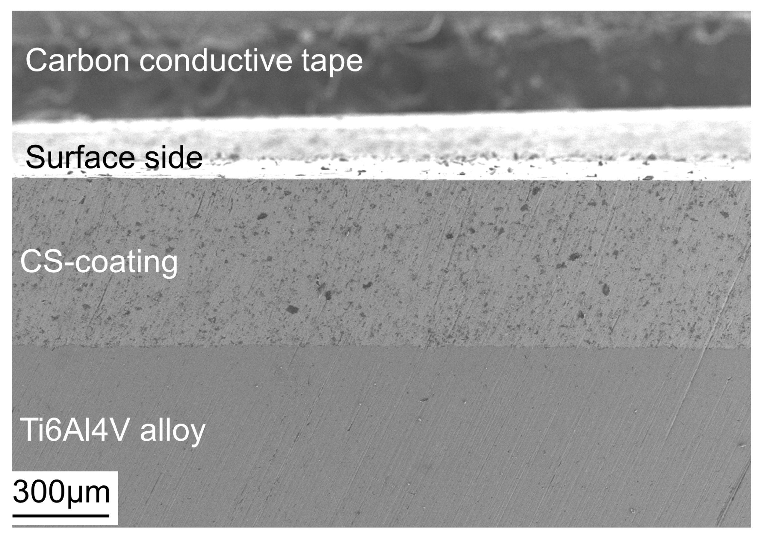
Ti6Al4V alloy was used as the substrate with the nominal chemical composition presented in Table 1. Alumina-reinforced aluminum coating was deposited on the Ti6Al4V substrate by cold spraying. The CS-coating was employed by using a mixture of 40 wt.% α-Al2O3 powder and 60 wt.% aluminum powder. Cold spraying was conducted by a low-pressure cold spray machine (LP-TCY-II, Tianchengyu, Beijing, China). Compressed air was used as the process gas, the working pressure was maintained at 0.8 MPa, the distance from the nozzle to the substrate was 10 mm, and the traverse speed of the nozzle during spraying was 5 mm/s. The thickness of the CS-coating was 500 ± 30 μm, as shown in Figure 1.
Specimens of size 20 × 20 × 5 mm3 were cut from the Ti6Al4V plate with and without CS-coating using a wire cut electrical discharge machine. Prior to the PEO process, each specimen was connected to a copper wire and then mounted in epoxy resin to provide a 20 × 20 mm2 working area. The working surfaces of the specimens were successively wet-ground up to 1500 grit using emery abrasive papers, rinsed in distilled water, and dried in air.
2.2. Coatings Preparation and Process Parameters
A 750 V/5 A power source (NHWYM750-5, Jinannenghua, Jinan, China) was employed for applying the pulsed wave forms during the PEO treatment. A 10 L stainless container equipped with magnetic stirring and cooling system was used as cathode. The electrolyte temperature was kept at 30 ± 5 °C.
For the Ti6Al4V specimens with CS-coating, the PEO process was performed under galvanostatic conditions in electrolyte containing 5 g/L Na2SiO3 and 1 g/L KOH. Two types of current modes were employed: a soft sparking mode and a unipolar mode. In the soft sparking mode, the anodic and cathodic currents were set at 30 and 33.33 A/dm2, respectively, leading to a ratio of Qp/Qn = 0.9. In unipolar mode, the anodic current was set at 30 A/dm2. Details of process parameters are given in Table 2. The PEO samples processed under soft sparking mode and unipolar mode were coded as S1 and S2, respectively.
As a reference, Ti6Al4V alloy without CS-coating was also subjected to PEO treatment, and the sample was coded as S3. The PEO treatment was carried out under constant anodic voltage of 350 V and cathodic voltage of 60 V in an electrolyte comprising 10 g/L Na2SiO3, 3 g/L KOH, and 4 g/L NaH2PO4. Table 3 lists the PEO process parameters for the Ti6Al4V alloy.
2.3. Characterization Methods
The surfaces and the cross-sections of samples were examined using a scanning electron microscope (SEM, GeminiSEM 300, Carl Zeiss, Jena, Germany). An X-ray diffraction system (XRD, D8 advance, Bruker, Karlsruhe, Germany) was used to characterize the phase composition of the PEO coatings (Cu Kα radiation, accelerating voltage 40 kV, current 15 mA, scanning speed 20 °/min, step size 0.02°, and scan range of 20°–100°). A Vickers hardness tester (HX-1000TM, Baoleng, Shanghai, China) was employed to measure the cross-sectional hardness of the PEO coatings with a load of 100 g and dwelling time of 15 s. An eddy current thickness meter (TT230, Beijing, China) was used to determine the thickness of the PEO coatings. The wear resistance of the Ti6Al4V alloy with and without PEO coatings were evaluated by a high-speed reciprocating friction tester (HSR-2M, Zhongkekaihua, Lanzhou, China). A ball (WC-6Co material, 6 mm in diameter) was pressed against the surface of the specimen under the load of 4.9 N for reciprocating motion. The travel distance was 4 mm, the reciprocating frequency was 5 Hz, and the wear test lasted for 30 min. Coefficients of friction (COF) were recorded during the sliding tests. After the sliding tests, a laser confocal microscope (OLS4000, Olympus, Tokyo, Japan) was used to measure the morphologies and depth profiles of the wear tracks. The cross-sectional area of wear tracks was obtained from the Olympus control software. Wear rates of specimens were calculated using the following equation [24]:
where ω is wear rate, mm3/(Nm); l is length of wear track, mm; S is cross sectional area of wear track, mm2; N is load, N; and L is sliding distance, m.
3. Results and Discussion
3.1. The Cell Voltage–Time and Current Density–Time Responses during PEO Treatment
The anodic voltage-versus-time plot during PEO of the Ti6Al4V alloy with CS-coating is shown in Figure 2. The curves for samples processed under soft sparking mode and unipolar mode both consisted of three stages. At stage I, an abrupt linear increase in voltage was observed within a short period of time. This stage was similar to conventional anodization which involved the rapid formation of an initial thin oxide film. At the end of stage I, the dielectric breakdown of the oxide film occurred.
At stage II, a large number of yellow discharges were observed, covering the entire surface of the sample evenly for both sample S1 and sample S2. The voltage kept increasing slowly and reached to 540 V and 587 V at the end of section II for samples S1 and S2, respectively. For sample S1, at about 540 s, tiny white-blue discharges were observed, preferentially starting at edges of the sample, then moving towards the center with increasing time. After all the surface was covered by the white-blue discharges, the voltage tended to decrease. In the meantime, the light and sound produced by the discharges became weaker. All these phenomena indicated that the PEO process gradually transited to the soft sparking regime [25].
At stage III, for sample S1, the anodic voltage decreased from 540 to 420 V. White-blue discharges covered the whole area around the specimen at a high population density. For sample S2, the discharges became more intense, their color changed gradually from yellow to orange, and the voltage increased to 622 V at the end of the test.
Figure 3 shows the cell current density-versus-time curve recorded during PEO treatment of Ti6Al4V alloy. In the first stage (0–5 s), the current density increased linearly with a very steep slope. This stage corresponded to the anodization process which developed a thin passive film via oxidation of the metal surface. At the second stage (6–100 s), micro-discharges were started due to the high applied electrical field. At this stage, the current density decreased quickly with time, due to the formation of a dense and thick oxide layer. The formation of the oxide layer increased the electrical resistance at the substrate/electrolyte interface and, hence, decreased the current density according to Ohm’s law. At stage III (100–1020 s), the current density decreased slowly, reaching 0.1 A at the end of the process. During this stage, sparks scanned the entire sample surface, leading to the formation of the oxide layer.
3.2. Morphology of Coatings
Figure 4 compared the surface and cross-section morphologies of the samples processed under different conditions. Figure 4a shows the surface morphology of the PEO coating formed on sample S1. The use of the soft sparking mode resulted in the formation of a “sponge”-like structure with fine open pores. The pores were formed by the gas evolution during the PEO process. Figure 4b showed the cross-section morphology of sample S1. Two distinct regions could be recognized from the figure, the inner CS-coating and the outer PEO coating. The CS-coating was compact with a thickness of about 220 ± 5 μm, and some Al2O3 particles were clearly visible in the aluminum matrix. The thickness of the PEO coating was uniform with a value of 115 ± 4 μm. The PEO coating could be subdivided into two layers, the outer porous layer and the inner dense layer, which was similar with the PEO coatings prepared on bulk aluminum alloys under soft sparking mode [26,27]. The outer layer was characterized by a number of interconnected tiny pores, while the inner layer exhibited a dense compact structure due to the reduction of long-lived and strong discharges by using the soft sparking mode. It is noteworthy that no Al2O3 particles were found in the PEO coating. The reason might be that the Al2O3 particles were melted and integrated into the PEO coating during the PEO process because the melting point of Al2O3 is 2072 °C [28] which could be reached within a few milliseconds at the location of micro discharges [26,29].
The PEO coating formed under unipolar current mode showed a cracked pancake-like morphology (site “A” in Figure 4b) along with dispersed fine round particles (site “B” in Figure 4b). In the center of each pancake-like structure, a micropore was observed. The pancake-like structure was a typical feature of PEO coating on aluminum [8]. Figure 4d showed the cross-section morphology of the coating. The thickness of the oxide scale was not so uniform with a value of 76 ± 10 μm, much less than that formed under soft sparking mode. There were large cavities that appeared as a band beneath the PEO coating. The connected large cavities were developed by strong “B” type discharges as reported in Hussein’s model [30] which caused melting and vaporizing of both the substrate alloy and the dielectric oxide layer. The molten materials erupted from discharge channels, and some gases were trapped in the coating/substrate interface layer, turning into cavities.
The surface and cross-section views of the PEO coating directly fabricated on the Ti6Al4V alloy are shown in Figure 4e,f, respectively. It can be seen from Figure 4e that there were large numbers of pores with different diameters along with few micro-cracks on the surface, which are typical characteristics of PEO coatings formed on titanium alloy [31,32]. It can be seen from the cross-section view that there were also many pores in the PEO coating, and the thickness of the PEO coating was 70 ± 4 μm.
3.3. Phase Composition of Coatings
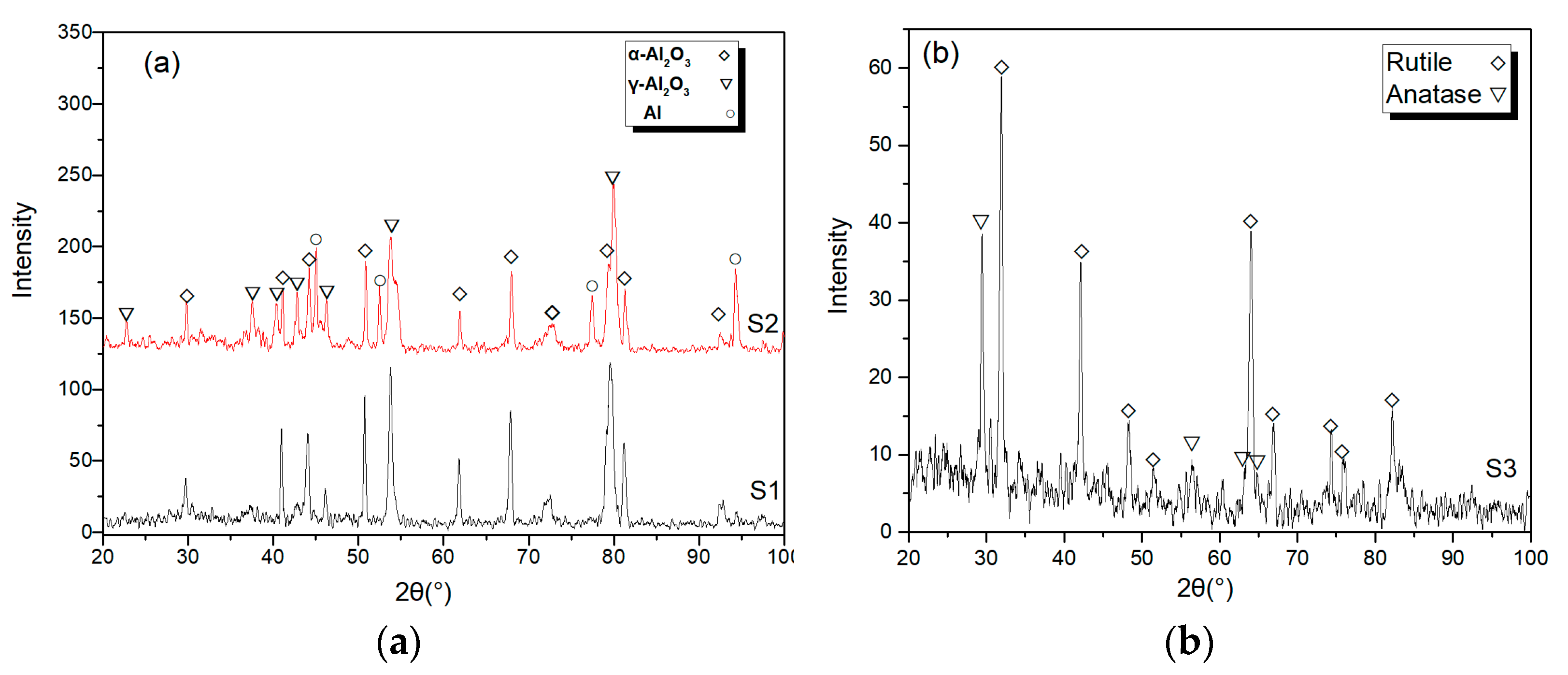
Figure 5a presents the XRD results of the PEO coatings prepared on Ti6Al4V alloy with CS-coating. For samples S1 and S2, the main phases in the oxide layer were α-Al2O3 and γ-Al2O3. Figure 5b presents the XRD result of the PEO coating directly fabricated on the Ti6Al4V alloy. The spectra revealed that the coating was mainly composed of rutile and the anatase, which was in agreement with the results given in literature [33,34]. The relative quantity of the α-Al2O3 and γ-Al2O3 phases of samples S1 and S2 was semi-qualitatively compared by taking the height ratio of the (113) peak for α-Al2O3 and (400) peak for γ-Al2O3 [35,36]. The α-Al2O3/γ-Al2O3 peak height ratios for samples S1 and S2 were 0.8955 and 0.7966, respectively. The result indicated that relatively more α-Al2O3 was formed by using the soft sparking mode. There were two possible reasons for this phenomenon. Firstly, the PEO coating formed under the soft sparking mode was relatively thicker and more compact than that formed under unipolar mode, which resulted in a lower thermal conductivity of the coating. The thermal energy could accumulate in the coating and induced a temperature rise high enough to cause the γ→α-Al2O3 phase transition [35]. Secondly, the hydrogen species generated during the cathodic period would provide ‘seeds’ for the γ→α phase transition [27]. Another noticeable feature was that intense diffraction peaks of the Al phase were detected in sample S2. This was largely because the oxide layer formed on sample S2 was thin and porous. The CS-coating could be detected directly by X-rays. The Al phase diffraction peaks of sample S1 were too small to distinguish, demonstrating that the ceramic coating formed under soft sparking mode was thick and compact, which was consistent with Figure 4.
3.4. Micro Hardness of Coatings
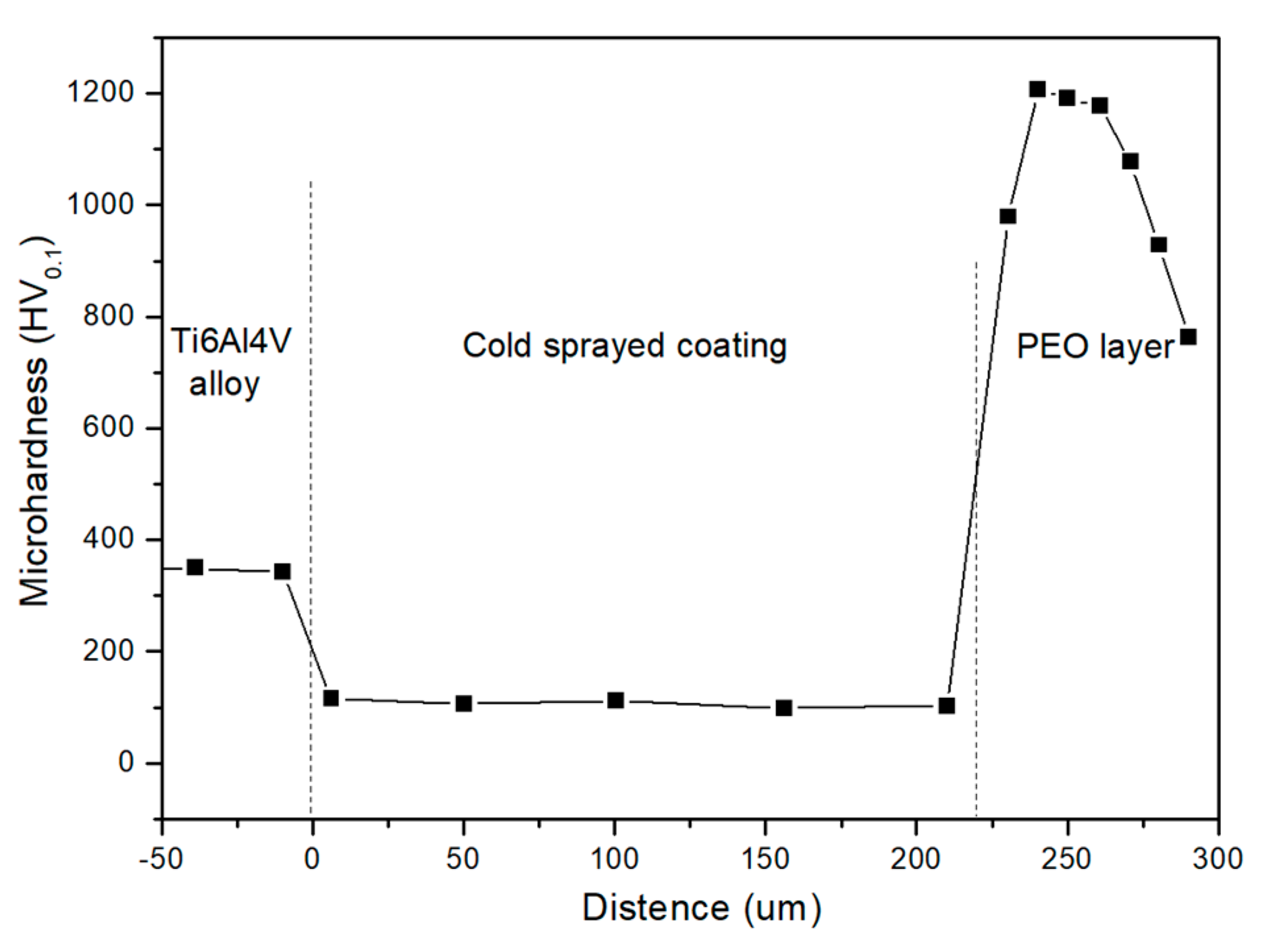
The microhardness values were measured on the cross-section of the PEO coatings. The average microhardness values of the PEO coating on samples S1, S2, and S3 were 1046 ± 165 HV0.1, 783 ± 281 HV0.1, and 539 ± 173 HV0.1, respectively, as shown in Figure 6. The PEO coating of sample S1 exhibited much higher microhardness than the other two samples due to its compact structure and a large number of α-Al2O3 phases. Figure 7 depicts the variation of cross-sectional microhardness of sample S1 as a function of distance from the Ti6Al4V substrate/CS-coating interface. The microhardness values of the Ti6Al4V substrate and the CS-coating were 346 ± 5 HV0.1 and 107 ± 6 HV0.1, respectively. The microhardness of the PEO coating increased first and then decreased with increasing distance from the CS-coating/PEO coating interface. The variation in hardness along the coating thickness could be explained by the change of phase composition and microstructure of the PEO coating. During the PEO process of the aluminum alloy, the PEO coating grew towards the side of the aluminum alloy, and the aluminum first oxidized to γ-Al2O3 [37,38]. Afterwards, a successive transformation from γ-Al2O3 to α-Al2O3 occurred due to the high temperature around the plasma discharge channels. This led to the relative high γ-Al2O3 content at the bottom of the PEO coating and the enrichment of α-Al2O3 in the middle region of the PEO coating [27,37]. Since the hardness values of the γ-Al2O3 and α-Al2O3 phase are 806 and 2183 HV, respectively [39], it was found that the middle region of the PEO coating was harder than the bottom region. The measurement of low hardness values close to the outermost regions could be attributed to the high micro-porosity concentration as shown in Figure 4b.
3.5. Wear Test
3.5.1. Coefficients of Friction (COF)
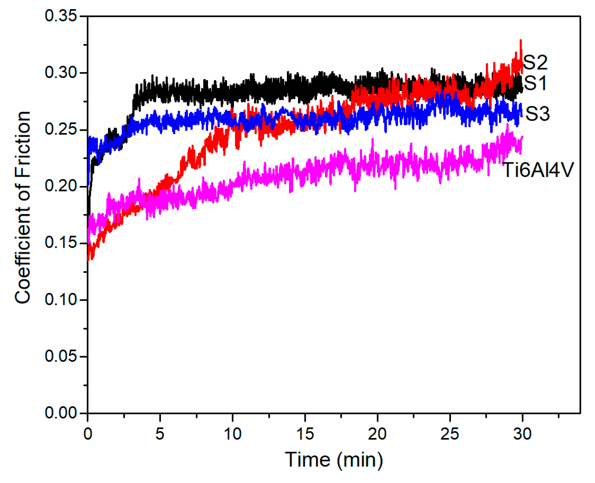
Figure 8 shows the COF versus time of samples worn under a load of 4.9 N. As can be seen from the result, the COF of sample S1 increased rapidly at the initial 4.0 min of the wear test, corresponding to the wearing off the outer loose layer. After that, the COF maintained at a steady range from 0.27 to 0.30 due to the decrease of the PEO coating roughness. For sample S2, the COF increased rapidly at the first 10 min of the test and then kept increasing slowly to 0.31 for the remaining time of the test. The COF changing trend of sample S3 was similar to that of sample S1, increased quickly at the beginning of the test and then maintained at a steady value, except that the oscillation was serious. The COF of the uncoated Ti6Al4V alloy was lower than the samples with PEO coatings. During the test, the COF gradually increased from 0.14 to 0.24 and was accompanied by severe oscillation. The oscillation of COF suggested that the tribological behavior of the uncoated Ti6Al4V alloy was poor, although the COF was not very high.
3.5.2. Friction Morphology
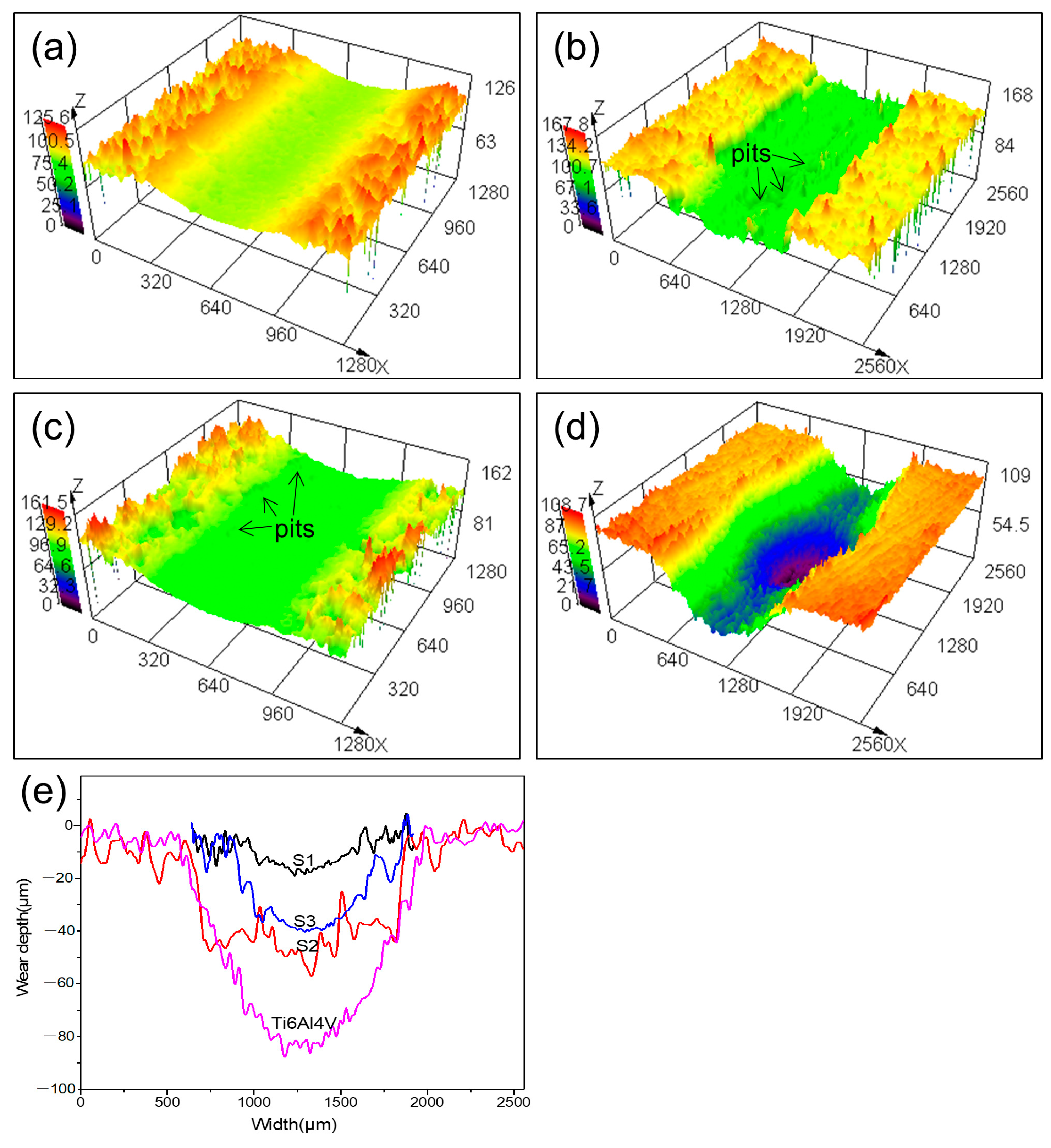
The 3D morphologies of the wear tracks for the coated and uncoated Ti6Al4V alloy were shown in Figure 9a–d, respectively, and the depth profiles of the wear tracks are shown in Figure 9e. It can be seen from Figure 9a that the wear track of the sample S1 was quite smooth and showed no evidence of detachment of the PEO coating, indicating that the mechanism of the wear was mainly abrasive wear. The width and depth of the wear track were the lowest of the four wear tracks, revealing an excellent wear performance of the PEO coating. It can be seen from Figure 9b that the wear track of sample S2 was much wider (around 1290.3 μm) and deeper (more than 56.4 μm) compared to sample S1. It is worth noting that many spalled pits appeared on the wear track, which increased the roughness of the wear track and led to a high COF. The formation of pits was caused by the detachment of the PEO coating during the sliding test. As shown in Figure 4d, the PEO coating formed under unipolar mode was thin and cracked, and there were large cavities beneath the PEO coating. During the sliding test, the PEO coating was easily fractured and peeled off, as it was brittle and the bonding force between the PEO coating and the CS-coating was weak. Therefore, abrasive wear and brittle fractures were the main wear damage for the PEO coating formed on sample S2. The wear track of sample S3 was smoother than that of sample S2; however, a few pits were also found on the wear track, indicating that a part of bulk oxides had peeled off. The width and depth of the wear track of sample S3 were larger than those of sample S1, as the pores in the PEO coating reduced the coating load bearing capacity. The wear track of the uncoated Ti6Al4V substrate was much wider and deeper than the coated samples, as shown in Figure 9d,e. The morphology of the wear track exhibited deep scratches and large deformations, similar to results reported in literature [40,41]. This could be attributed to the low hardness and high plasticity of the TC4 alloy, which made it deform easily and generate material loss under repeated force.
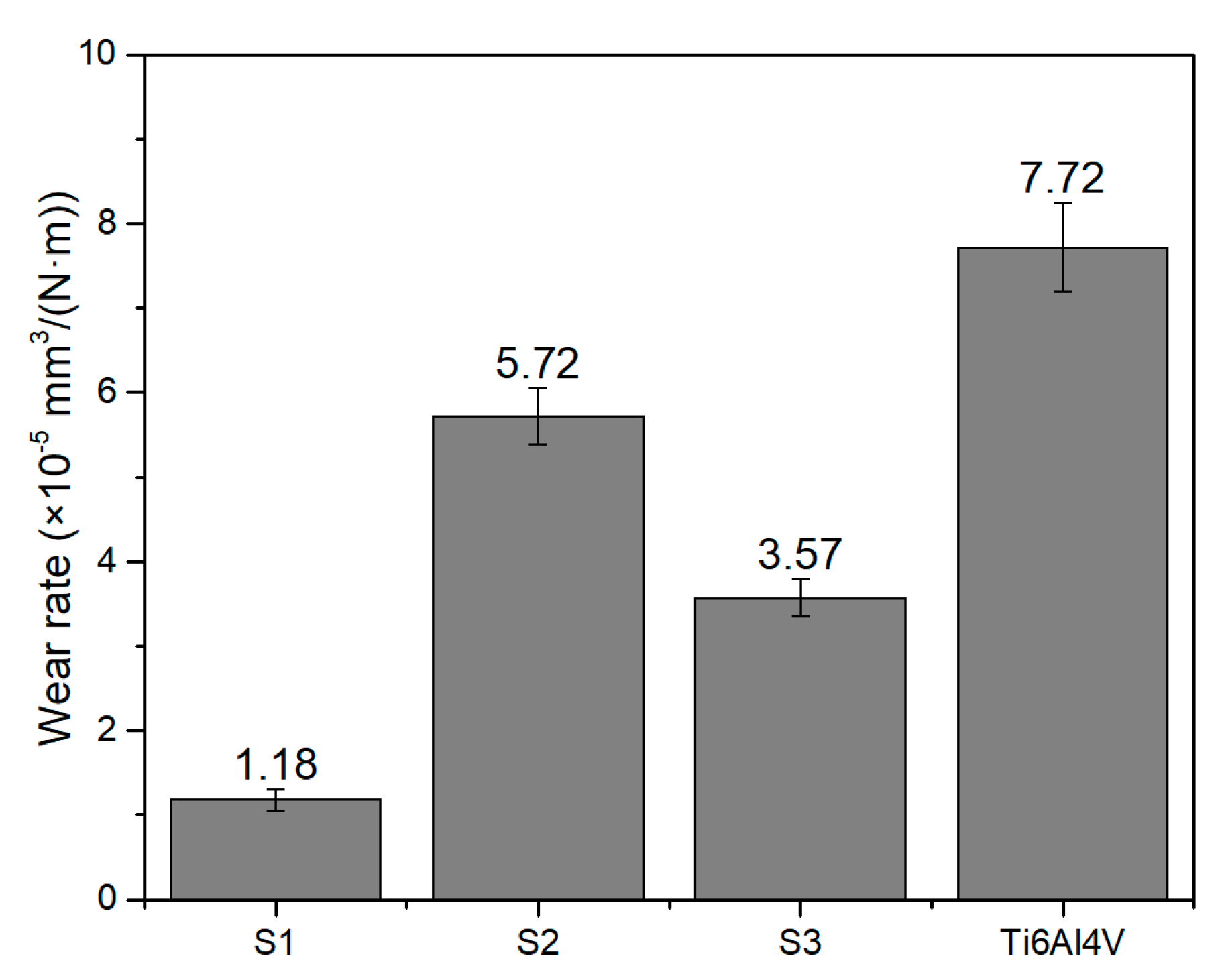
3.5.3. Wear Rate
The average wear rates of samples S1, S2, and S3 and uncoated Ti6Al4V alloy were calculated to be 1.18 × 10⁻⁵, 5.72 × 10⁻⁵, 3.57 × 10⁻⁵, and 7.72 × 10⁻⁵ mm3/(Nm), respectively, as shown in Figure 10. Sample S1 exhibited the lowest wear rate, which was only 15.28% of that of the Ti6Al4V substrate. The excellent wear resistance of the coating depended on both the phase constituents and the structures of the coatings. On the one hand, the PEO coating that formed on sample S1 was mainly composed of Al2O3 and had a higher content of α-Al2O3 than sample S2. The average hardness of the oxide layer that formed on sample S1 was higher than those that formed on samples S2 and S3. According to Archard’s wear law [42]:
where ω is the wear rate, K is the wear coefficient, L is the applied pressure, and H is the hardness of the material. The higher the hardness of a coating, the lower the wear loss obtained. On the other hand, the excellent wear resistance of the PEO coating depended on its micro-structure. The PEO coating that formed on sample S1 was more compact than the one that formed on samples S2 and S3, as can be seen in Figure 4, resulting in an excellent load bearing capacity of the coating.
The investigations indicated that the combination of cold spraying and PEO under soft sparking mode was a promising technique for improving the wear resistance of the Ti6Al4V alloy. It should be pointed out that one advantage of this combination treatment was that both the cold spray process and the PEO process were carried out under very low temperatures of no more than 200 °C. Therefore, the combination treatment had little thermal effect on the substrate alloy. Another thing that needs to be pointed out is that although the wear rate of S1 was low, the COF was still relatively high, as shown in Figure 8. Further research is needed to reduce the COF of the PEO coating formed under soft sparking mode, which can further increase the wear resistance of the PEO coating.
4. Conclusions
In this study, Ti6Al4V alloy with and without CS-coating was subjected to PEO treatment in order to prepare wear-resistant PEO coatings. The PEO treatment of the Ti6Al4V alloy with CS-coating was processed under soft sparking mode and unipolar mode, respectively. The following results were obtained:
- (1)
- The PEO coating that formed on the Ti6Al4V alloy with CS-coating under soft sparking mode had a more compact structure, relatively higher α-Al2O3 content, and higher micro hardness than that formed under unipolar mode.
- (2)
- The PEO coating that formed on Ti6Al4V base alloy was mainly composed of TiO2 and contained cracks and pores.
- (3)
- Among all the samples, the PEO coating that formed on CS-coating under soft sparking mode exhibited the best wear resistance with a wear rate of 1.18 × 10⁻⁵ mm3/(Nm). The excellent wear resistance of the coating depended on the higher α-Al2O3 content and compact structure of the coating.
- (4)
- The investigations indicated that the combination of cold spraying and PEO under soft sparking mode is a promising technique for improving the wear resistance of titanium alloys. Further research is needed to reduce the COF of the PEO coating formed under soft sparking mode.
Author Contributions
Conceptualization, M.S. and W.W.; methodology, M.S.; data curation, X.Z.; writing—original draft, M.S.; writing—review and editing, W.W. and H.Y.; funding acquisition, M.S. supervision, X.H. All authors have read and agreed to the published version of the manuscript.
Funding
This research was funded by Special Research Project of Shaanxi Provincial Department of Education (No. 18JK0475), and Shaanxi Provincial Natural Science Foundation (No. 2020JM-493).
Institutional Review Board Statement
Not applicable.
Informed Consent Statement
Not applicable.
Data Availability Statement
Data is contained within the article.
Conflicts of Interest
The authors declare no conflict of interest.
References
- Leyens, C.; Peters, M. Titanium and Titanium Alloys: Fundamentals and Applications; Wiley-VCH: Weinheim, Germany, 2003; pp. 19–22. [Google Scholar]
- Boyer, R.R. An overview on the use of titanium in the aerospace industry. Mater. Sci. Eng. A-Struct. 1996, 213, 103–114. [Google Scholar] [CrossRef]
- Zhang, T.G.; Zhuang, H.F.; Zhang, Q.; Yao, B.; Yang, F. Influence of Y2O3 on the microstructure and tribological properties of Ti-based wear-resistant laser-clad layers on TC4 alloy. Ceram. Int. 2020, 46, 13711–13723. [Google Scholar] [CrossRef]
- Li, X.; Hu, G.; Tian, J.; Tian, W.; Xie, W.; Li, X. Wear resistance enhancement of Ti-6Al-4 V Alloy by applying Zr-modified silicide coatings. J. Mater. Eng. Perform. 2018, 27, 1073–1082. [Google Scholar] [CrossRef]
- Jin, J.; Duan, H.; Li, X. The influence of plasma nitriding on microstructure and properties of CrN and CrNiN coatings on Ti6Al4V by magnetron sputtering. Vacuum 2017, 136, 112–120. [Google Scholar] [CrossRef]
- Liu, W.; Blawert, C.; Zheludkevich, M.L.; Lin, Y.; Talha, M.; Shi, Y.; Chen, L. Effects of graphene nanosheets on the ceramic coatings formed on Ti6Al4V alloy drill pipe by plasma electrolytic oxidation. J. Alloy Compd. 2019, 789, 996–1007. [Google Scholar] [CrossRef]
- Mu, M.; Liang, J.; Zhou, X.; Xiao, Q. One-step preparation of TiO2/MoS2 composite coating on Ti6Al4V alloy by plasma electrolytic oxidation and its tribological properties. Surf. Coat. Tech. 2013, 214, 124–130. [Google Scholar] [CrossRef]
- Kaseem, M.; Fatimah, S.; Nashrah, N.; Ko, Y.G. Recent progress in surface modification of metals coated by plasma electrolytic oxidation: Principle, structure, and performance. Prog. Mater. Sci. 2021, 117, 100735. [Google Scholar] [CrossRef]
- Bailing, J.; Yaming, W. Plasma electrolytic oxidation treatment of aluminium and titanium alloys. In Surface Engineering of Light Alloys; Dong, H., Ed.; Woodhead Publishing: Cambridge, UK, 2010; Volume 5, pp. 110–154. [Google Scholar]
- Fazel, M.; Salimijazi, H.R.; Golozar, M.A.; Garsivaz Jazi, M.R. A comparison of corrosion, tribocorrosion and electrochemical impedance properties of pure Ti and Ti6Al4V alloy treated by micro-arc oxidation process. Appl. Surf. Sci. 2015, 324, 751–756. [Google Scholar] [CrossRef]
- Qin, Y.K.; Xiong, D.S.; Li, J.L.; Tyagi, R. Compositions and tribological properties of PEO coatings on Ti6Al4V alloy. Surf. Eng. 2017, 33, 895–902. [Google Scholar] [CrossRef]
- Bertuccioli, C.; Garzoni, A.; Martini, C.; Morri, A.; Rondelli, G. Plasma electrolytic oxidation (PEO) layers from silicate/phosphate baths on Ti-6Al-4V for biomedical components: Influence of deposition conditions and surface finishing on dry sliding behaviour. Coatings 2019, 9, 614. [Google Scholar] [CrossRef] [Green Version]
- Simchen, F.; Sieber, M.; Kopp, A.; Lampke, T. Introduction to plasma electrolytic oxidation-an overview of the process and applications. Coatings 2020, 10, 628. [Google Scholar] [CrossRef]
- Tsai, D.; Chen, G.; Chou, C. Probe the micro arc softening phenomenon with pulse transient analysis in plasma electrolytic oxidation. Surf. Coat. Technol. 2019, 357, 235–243. [Google Scholar] [CrossRef]
- Rogov, A.B.; Yerokhin, A.; Matthews, A. The role of cathodic current in plasma electrolytic oxidation of aluminum: Phenomenological concepts of the “soft sparking” mode. Langmuir 2017, 33, 11059–11069. [Google Scholar] [CrossRef]
- Hakimizad, A.; Raeissi, K.; Santamaria, M.; Asghari, M. Effects of pulse current mode on plasma electrolytic oxidation of 7075 Al in Na2WO4 containing solution: From unipolar to soft-sparking regime. Electrochim. Acta 2018, 284, 618–629. [Google Scholar] [CrossRef]
- Koshuro, V.A.; Fomina, M.A.; Rodionov, I.V.; Fomin, A.A. Nanoporous structure of coatings formed by thermal spraying of aluminum oxide with further microarc oxidation on titanium alloy VT6 implants. Biomed. Eng. 2016, 50, 54–57. [Google Scholar] [CrossRef]
- Koshuro, V.; Fomin, A.; Rodionov, I. Composition, structure and mechanical properties of metal oxide coatings produced on titanium using plasma spraying and modified by micro-arc oxidation. Ceram. Int. 2018, 44, 12593–12599. [Google Scholar] [CrossRef]
- Kang, S.; Tu, W.; Han, J.; Li, Z.; Cheng, Y. A significant improvement of the wear resistance of Ti6Al4V alloy by a combined method of magnetron sputtering and plasma electrolytic oxidation (PEO). Surf. Coat. Technol. 2019, 358, 879–890. [Google Scholar] [CrossRef]
- Hu, C.; Chiu, P. Wear and corrosion resistance of pure titanium subjected to aluminization and coated with a microarc oxidation ceramic coating. Int. J. Electrochem. Sci. 2015, 10, 4290–4302. [Google Scholar]
- Moridi, A.; Hassani-Gangaraj, S.M.; Guagliano, M.; Dao, M. Cold spray coating: Review of material systems and future perspectives. Surf. Eng. 2014, 30, 369–395. [Google Scholar] [CrossRef]
- Huang, G.; Wang, H.; Li, X.; Xing, L.; Zhou, J. Deposition efficiency of low pressure cold sprayed aluminum coating. Mater. Manuf. Process. 2018, 33, 1100–1106. [Google Scholar] [CrossRef]
- Choi, W.B.; Li, L.; Luzin, V.; Neiser, R.; Gnäupel-Herold, T.; Prask, H.J.; Sampath, S.; Gouldstone, A. Integrated characterization of cold sprayed aluminum coatings. Acta Mater. 2007, 55, 857–866. [Google Scholar] [CrossRef]
- Mi, P.; Zhao, H.; Wang, T.; Ye, F. Sliding wear behavior of HVOF sprayed WC-(nano-WC-Co) coating at elevated temperatures. Mater. Chem. Phys. 2018, 206, 1–6. [Google Scholar] [CrossRef]
- Tsai, D.; Chou, C. Review of the soft sparking issues in plasma electrolytic oxidation. Metals 2018, 8, 105. [Google Scholar] [CrossRef] [Green Version]
- Martin, J.; Nominé, A.; Ntomprougkidis, V.; Migot, S.; Bruyère, S.; Soldera, F.; Belmonte, T.; Henrion, G. Formation of a metastable nanostructured mullite during plasma electrolytic oxidation of aluminium in “soft” regime condition. Mater. Des. 2019, 180, 107977. [Google Scholar] [CrossRef]
- Rogov, A.B.; Matthews, A.; Yerokhin, A. Role of cathodic current in plasma electrolytic oxidation of Al: A quantitative approach to in-situ evaluation of cathodically induced effects. Electrochim. Acta 2019, 317, 221–231. [Google Scholar] [CrossRef]
- Patnaik, P. Handbook of Inorganic Chemicals; McGraw-Hill Professional: New York, NY, USA, 2002; pp. 11–12. [Google Scholar]
- Hussein, R.O.; Nie, X.; Northwood, D.O. Effect of current mode on the plasma discharge, microstructure and corrosion resistance of oxide coatings produced on 1100 aluminum alloy by plasma electrolytic oxidation. WIT Trans. Eng. Sci. 2019, 124, 3–16. [Google Scholar]
- Hussein, R.O.; Nie, X.; Northwood, D.O.; Yerokhin, A.; Matthews, A. Spectroscopic study of electrolytic plasma and discharging behaviour during the plasma electrolytic oxidation (PEO) process. J. Phys. D 2010, 43, 105203. [Google Scholar] [CrossRef]
- Kumari, R.; Blawert, C.; Majumdar, J.D. Microstructures and properties of plasma electrolytic oxidized Ti alloy (Ti–6Al–4V) for bio-implant application. Metall. Mater. Trans. A Phys. Metall. Mater. Sci. 2016, 47, 788–800. [Google Scholar] [CrossRef]
- Ríos, J.M.; Quintero, D.; Castaño, J.G.; Echeverría, F.; Gómez, M.A. Comparison among the lubricated and unlubricated tribological behavior of coatings obtained by PEO on the Ti6Al4V alloy in alkaline solutions. Tribol. Int. 2018, 128, 1–8. [Google Scholar] [CrossRef]
- Tekin, K.C.; Malayoglu, U.; Shrestha, S. Tribological behaviour of plasma electrolytic oxide coatings on Ti6Al4V and cp-Ti alloys. Surf. Eng. 2016, 32, 435–442. [Google Scholar] [CrossRef]
- Wheeler, J.M.; Collier, C.A.; Paillard, J.M.; Curran, J.A. Evaluation of micromechanical behaviour of plasma electrolytic oxidation (PEO) coatings on Ti-6Al-4V. Surf. Coat. Technol. 2010, 204, 3399–3409. [Google Scholar] [CrossRef]
- Dehnavi, V.; Liu, X.Y.; Luan, B.L.; Shoesmith, D.W.; Rohani, S. Phase transformation in plasma electrolytic oxidation coatings on 6061 aluminum alloy. Surf. Coat. Technol. 2014, 251, 106–114. [Google Scholar] [CrossRef]
- Cheng, Y.; Cao, J.; Mao, M.; Peng, Z.; Skeldon, P.; Thompson, G.E. High growth rate, wear resistant coatings on an Al-Cu-Li alloy by plasma electrolytic oxidation in concentrated aluminate electrolytes. Surf. Coat. Technol. 2015, 269, 74–82. [Google Scholar] [CrossRef]
- Sieber, M.; Simchen, F.; Morgenstern, R.; Scharf, I.; Lampke, T. Plasma electrolytic oxidation of high-strength aluminium alloys—substrate effect on wear and corrosion performance. Metals 2018, 8, 356. [Google Scholar] [CrossRef] [Green Version]
- Wu, Y.-k.; Yang, Z.; Wang, R.-q.; Wu, G.-r.; Chen, D.; Wang, D.-d.; Liu, X.-t.; Li, D.-l.; Guo, C.-h.; Yu, S.-x.; et al. An investigation of microstructure evolution for plasma electrolytic oxidation (PEO) coated Al in an alkaline silicate electrolyte. Surf. Coat. Technol. 2018, 351, 136–152. [Google Scholar] [CrossRef]
- Krishna, L.R.; Gupta, P.S.V.N.; Sundararajan, G. The influence of phase gradient within the micro arc oxidation (MAO) coatings on mechanical and tribological behaviors. Surf. Coat. Technol. 2015, 269, 54–63. [Google Scholar] [CrossRef]
- Benea, L.; Mardare-Danaila, E.; Celis, J. Increasing the tribological performances of Ti–6Al–4V alloy by forming a thin nanoporous TiO2 layer and hydroxyapatite electrodeposition under lubricated conditions. Tribol. Int. 2014, 78, 168–175. [Google Scholar] [CrossRef]
- Yetim, A.F.; Yildiz, F.; Vangolu, Y.; Alsaran, A.; Celik, A. Several plasma diffusion processes for improving wear properties of Ti6Al4V alloy. Wear 2009, 267, 2179–2185. [Google Scholar] [CrossRef]
- Archard, J.F. Contact and rubbing of flat surfaces. J. Appl. Phys. 1953, 24, 981–988. [Google Scholar] [CrossRef]
Figure 1.
Cross-sectional morphology of Ti6Al4V alloy with CS-coating.

Figure 2.
Anodic voltage–time response during PEO of Ti6Al4V alloy with CS-coating using soft sparking mode and unipolar mode.
Figure 2.
Anodic voltage–time response during PEO of Ti6Al4V alloy with CS-coating using soft sparking mode and unipolar mode.
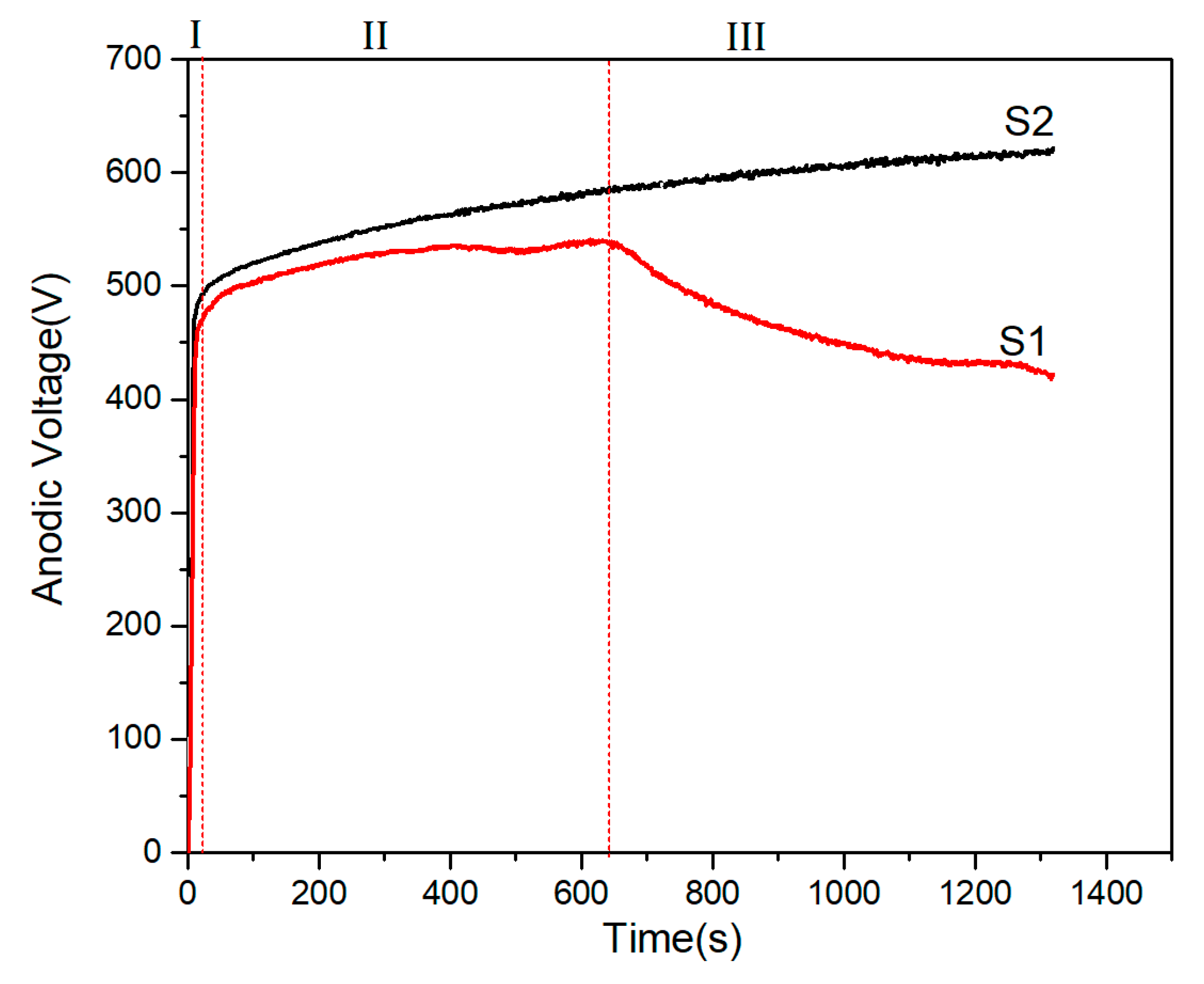
Figure 3.
Cell current density-versus-time responses during PEO treatments of the Ti6Al4V alloy.
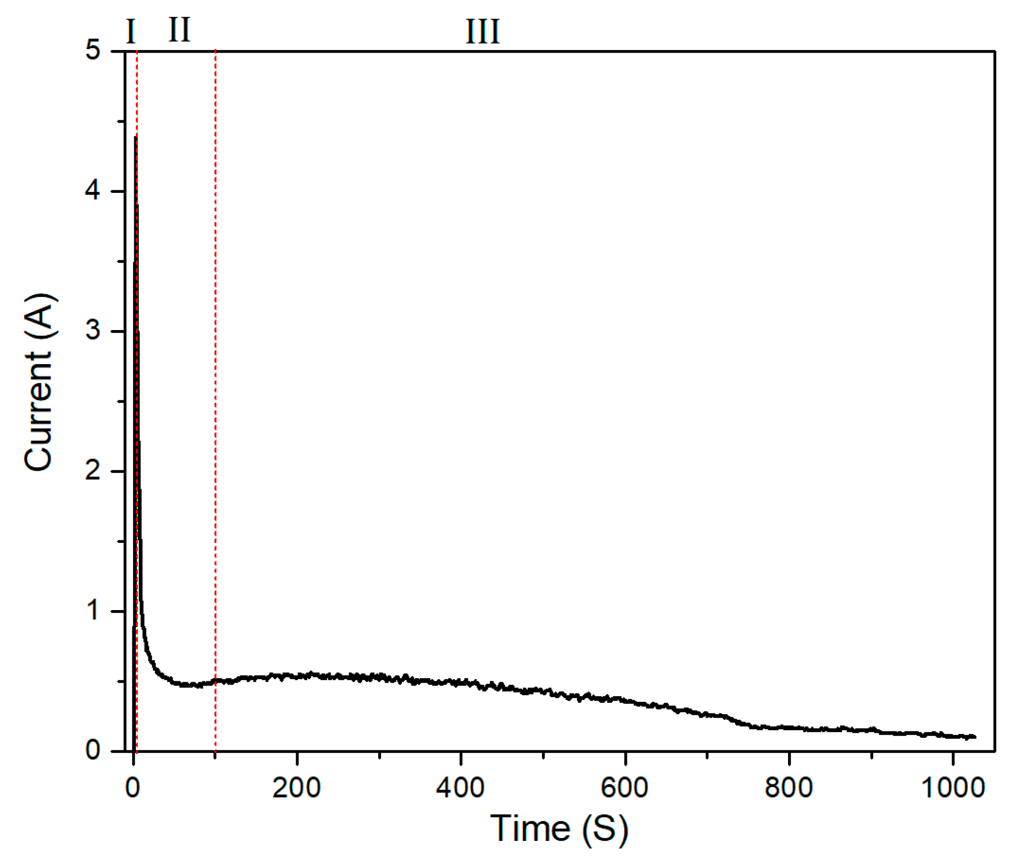
Figure 4.
Surface morphologies of PEO coatings on samples: (a) S1; (c) S2; (e) S3; cross-section morphologies of samples: (b) S1; (d) S2; (f) S3.
Figure 4.
Surface morphologies of PEO coatings on samples: (a) S1; (c) S2; (e) S3; cross-section morphologies of samples: (b) S1; (d) S2; (f) S3.
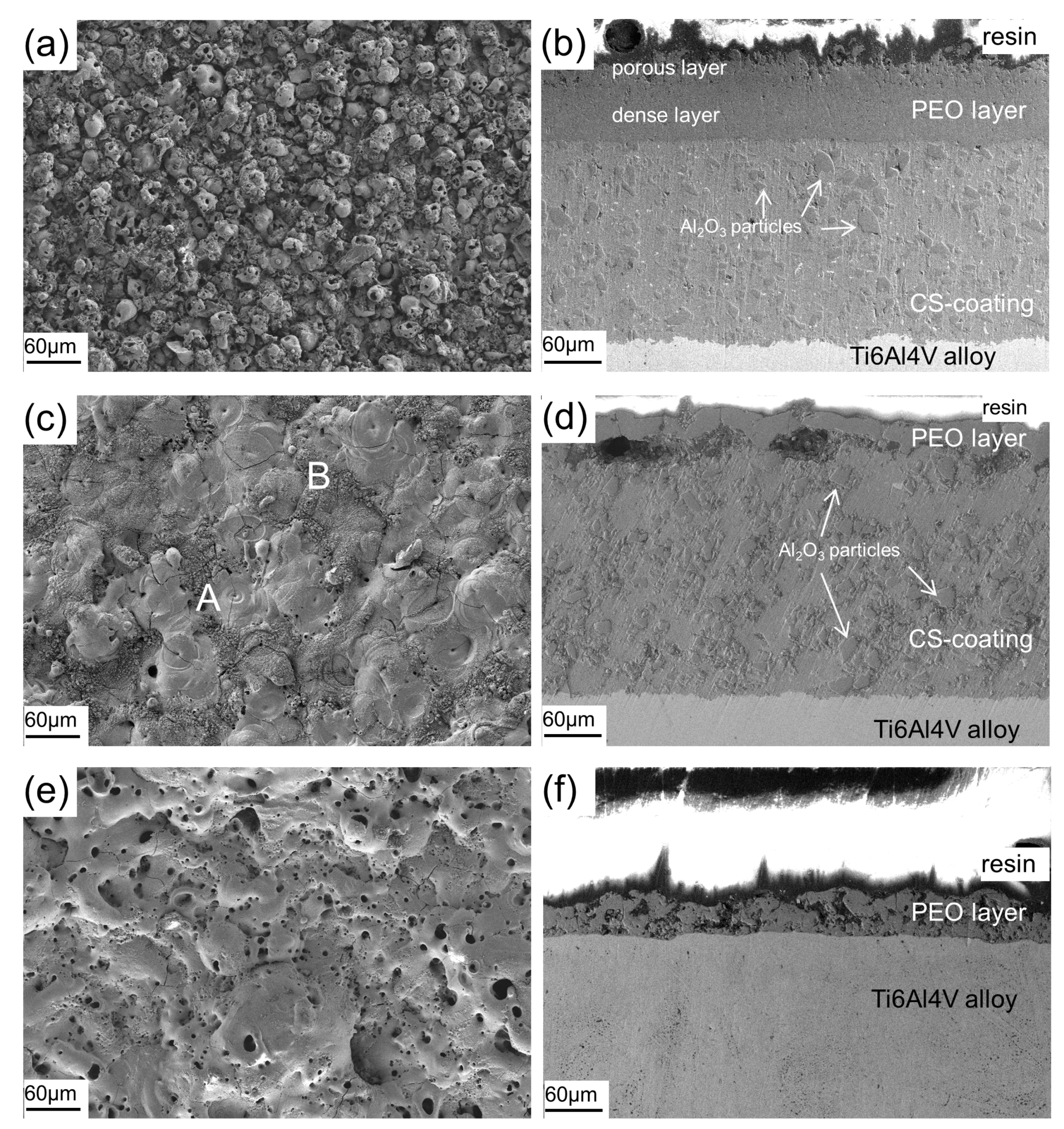
Figure 5.
X-ray diffraction patterns of PEO coatings: (a) S1, S2; (b) S3.

Figure 6.
Microhardness of PEO coatings on samples S1, S2, S3.
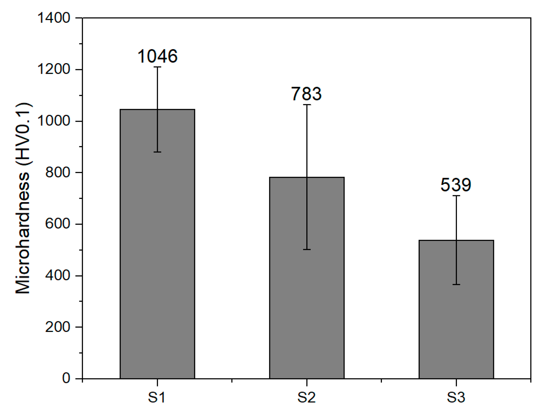
Figure 7.
Cross-sectional microhardness of sample S1 as a function of the distance from the Ti6Al4V substrate/CS-coating interface.
Figure 7.
Cross-sectional microhardness of sample S1 as a function of the distance from the Ti6Al4V substrate/CS-coating interface.

Figure 8.
The variation of COF versus time of coated and uncoated Ti6Al4V alloy.

Figure 9.
3D morphology of wear tracks on different samples (a) S1; (b) S2; (c) S3; (d) Ti6Al4V substrate; (e) cross-sectional profiles of wear tracks.
Figure 9.
3D morphology of wear tracks on different samples (a) S1; (b) S2; (c) S3; (d) Ti6Al4V substrate; (e) cross-sectional profiles of wear tracks.

Figure 10.
Wear rates of coated and uncoated Ti6Al4V alloy.


Table 1.
Chemical composition of the Ti6Al4V alloy (wt. %).
| Al | V | O | Fe | Ti |
|---|---|---|---|---|
| 5.5~6.9 | 3.5~4.5 | <0.2 | <0.4 | balance |
Table 2.
PEO process parameters for Ti6Al4V alloy with CS-coating.
| Sample Code | Mode | Time (s) | I+ (A) | I− (A) | (μs) | (μs) | (μs) | (μs) | Qp/Qn |
|---|---|---|---|---|---|---|---|---|---|
| S1 | Soft sparking | 1320 | 1.2 | 1.33 | 900 | 100 | 900 | 100 | 0.9 |
| S2 | unipolar | 1320 | 1.2 | N/A | 900 | 1100 | N/A | N/A | ∞ |
Table 3.
PEO process parameters for Ti6Al4V alloy without CS-coating.
| Sample Code | Time (s) | U+ (V) | U− (V) | (μs) | (μs) | (μs) | |
|---|---|---|---|---|---|---|---|
| S3 | 1020 | 350 | 60 | 900 | 100 | 900 | 100 |
Publisher’s Note: MDPI stays neutral with regard to jurisdictional claims in published maps and institutional affiliations. |
© 2021 by the authors. Licensee MDPI, Basel, Switzerland. This article is an open access article distributed under the terms and conditions of the Creative Commons Attribution (CC BY) license (https://creativecommons.org/licenses/by/4.0/).
Share and Cite
MDPI and ACS Style
Shao, M.; Wang, W.; Yang, H.; Zhang, X.; He, X. Preparation of Wear-Resistant Coating on Ti6Al4V Alloy by Cold Spraying and Plasma Electrolytic Oxidation. Coatings 2021, 11, 1288. https://doi.org/10.3390/coatings11111288
AMA Style
Shao M, Wang W, Yang H, Zhang X, He X. Preparation of Wear-Resistant Coating on Ti6Al4V Alloy by Cold Spraying and Plasma Electrolytic Oxidation. Coatings. 2021; 11(11):1288. https://doi.org/10.3390/coatings11111288
Chicago/Turabian StyleShao, Mingzeng, Wei Wang, Hongbo Yang, Xueer Zhang, and Xiaomei He. 2021. "Preparation of Wear-Resistant Coating on Ti6Al4V Alloy by Cold Spraying and Plasma Electrolytic Oxidation" Coatings 11, no. 11: 1288. https://doi.org/10.3390/coatings11111288
Note that from the first issue of 2016, this journal uses article numbers instead of page numbers. See further details here.