
Study of Slip Effects in Reverse Roll Coating Process Using Non-Isothermal Couple Stress Fluid

 , ,
, ,  and
and
Abstract
:1. Introduction
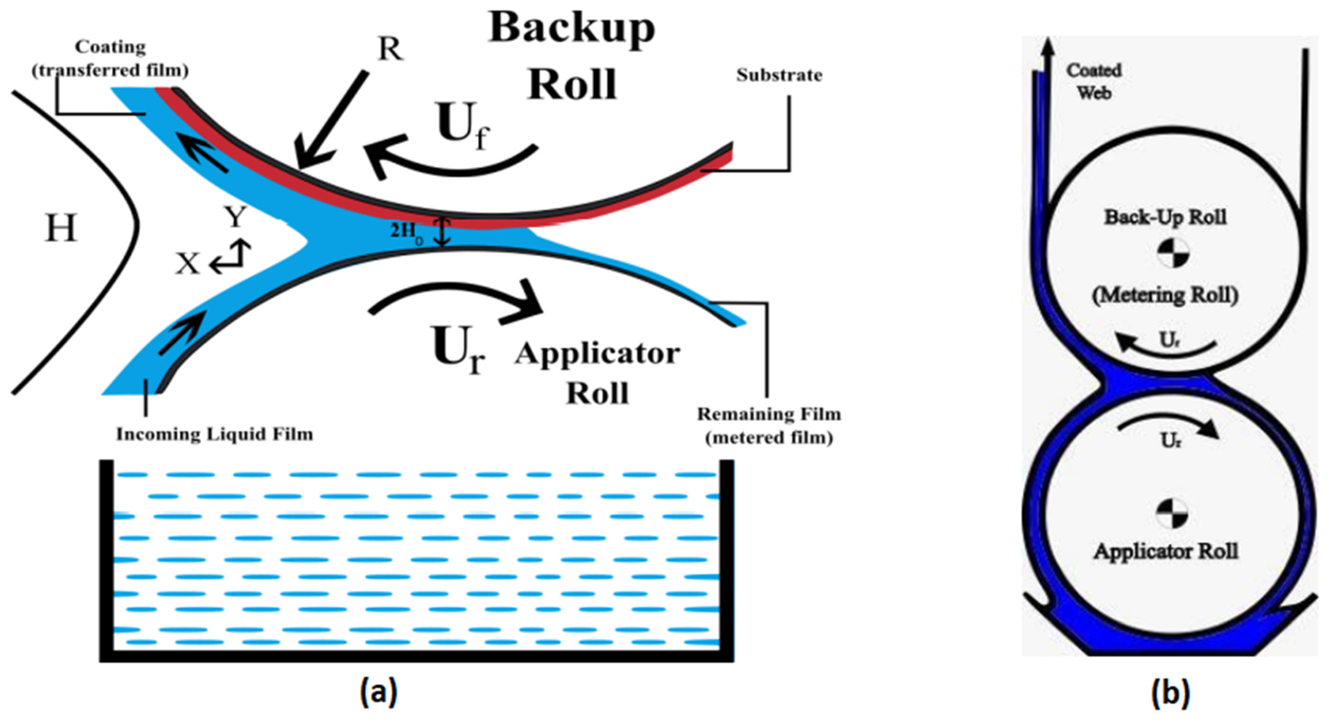
2. Problem Formulation
- The velocities of the rolls are defined as and .
- and are the velocities of forward and reverse roll, respectively, and R is the radius of the rolls.
- is the angular velocity and the subscripts and denote the reverse and forward, respectively.
- The gap between the two rolls is .
- is the velocities ratio.
- It is assumed that fluid may slip at the surface of the rolls. That is, the Navier slip conditions are taken at the surface of the rolls.
2.1. Governing Equations and Mathematical Modeling
- = fluid density
- = viscosity coefficient
- = couple stress fluid material constant
- = specific heat
- k = thermal conductivity
- T = Temperature
2.2. Solution to the Problem
3. Results and Discussion
4. Conclusions
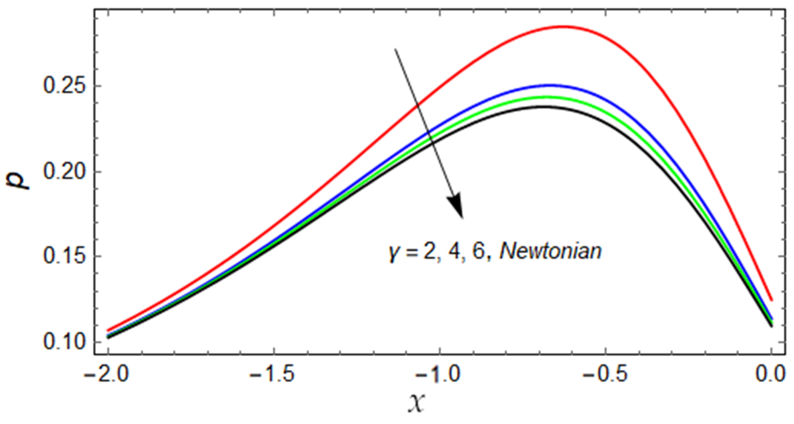
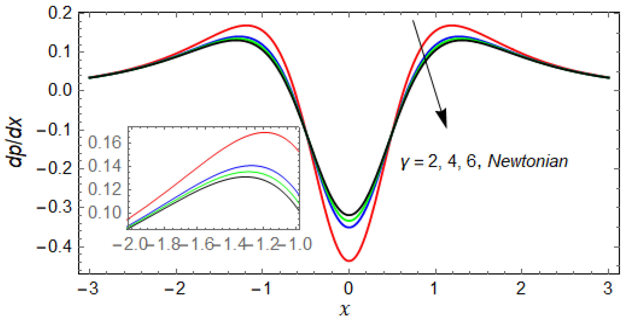
- The pressure and pressure gradient decreases for increasing values of the couple stress parameter, and for large values of the results for the Newtonian case are recovered.
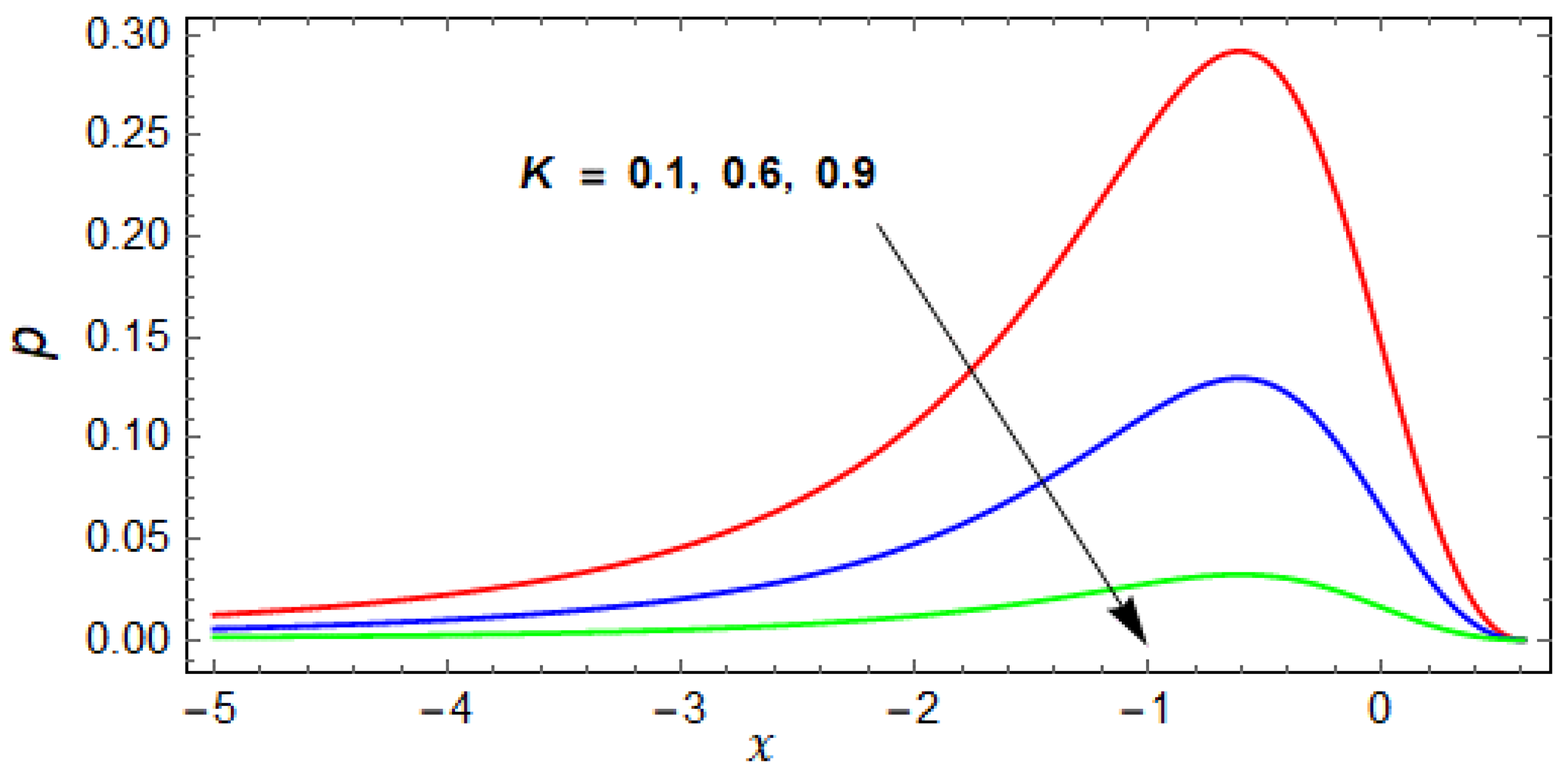
- The effect of velocity ratio K on pressure is the same as for the couple stress parameter but the impact is greater than .
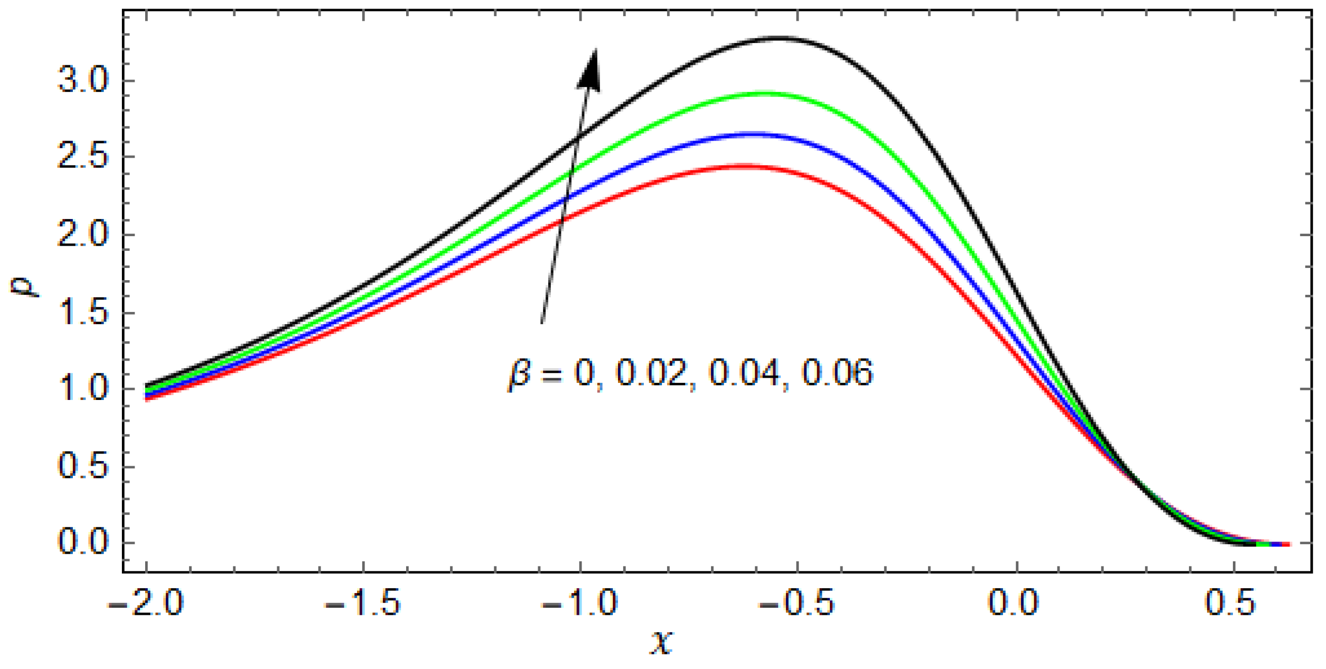
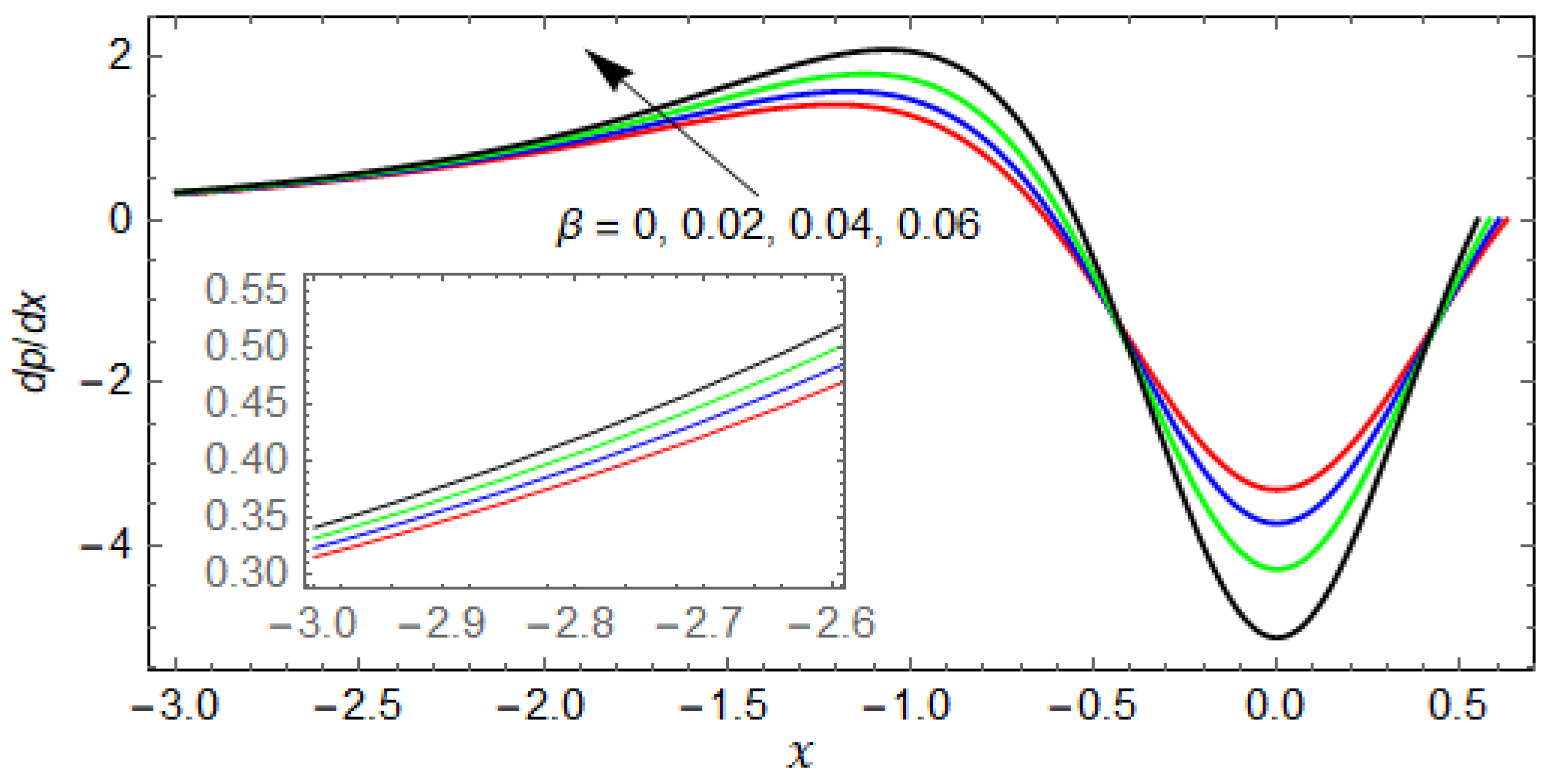
- The impact of the slip parameter on the pressure and pressure gradient is opposite to that of K and (i.e., the pressure and pressure gradient increase for increasing values of . This is because the fluid moves rapidly along the rollers due to slip and, consequently, the pressure and pressure gradient increase.
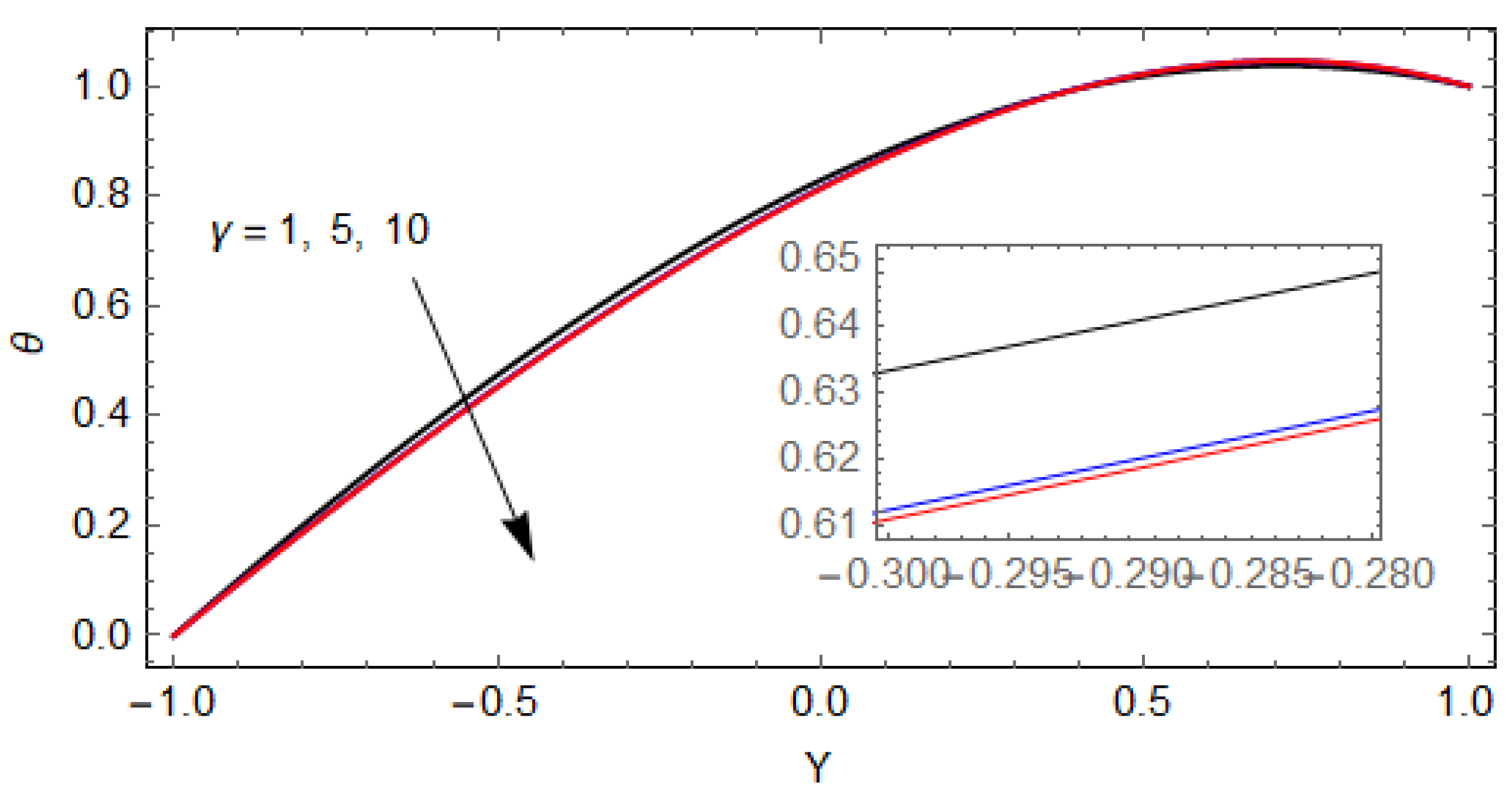
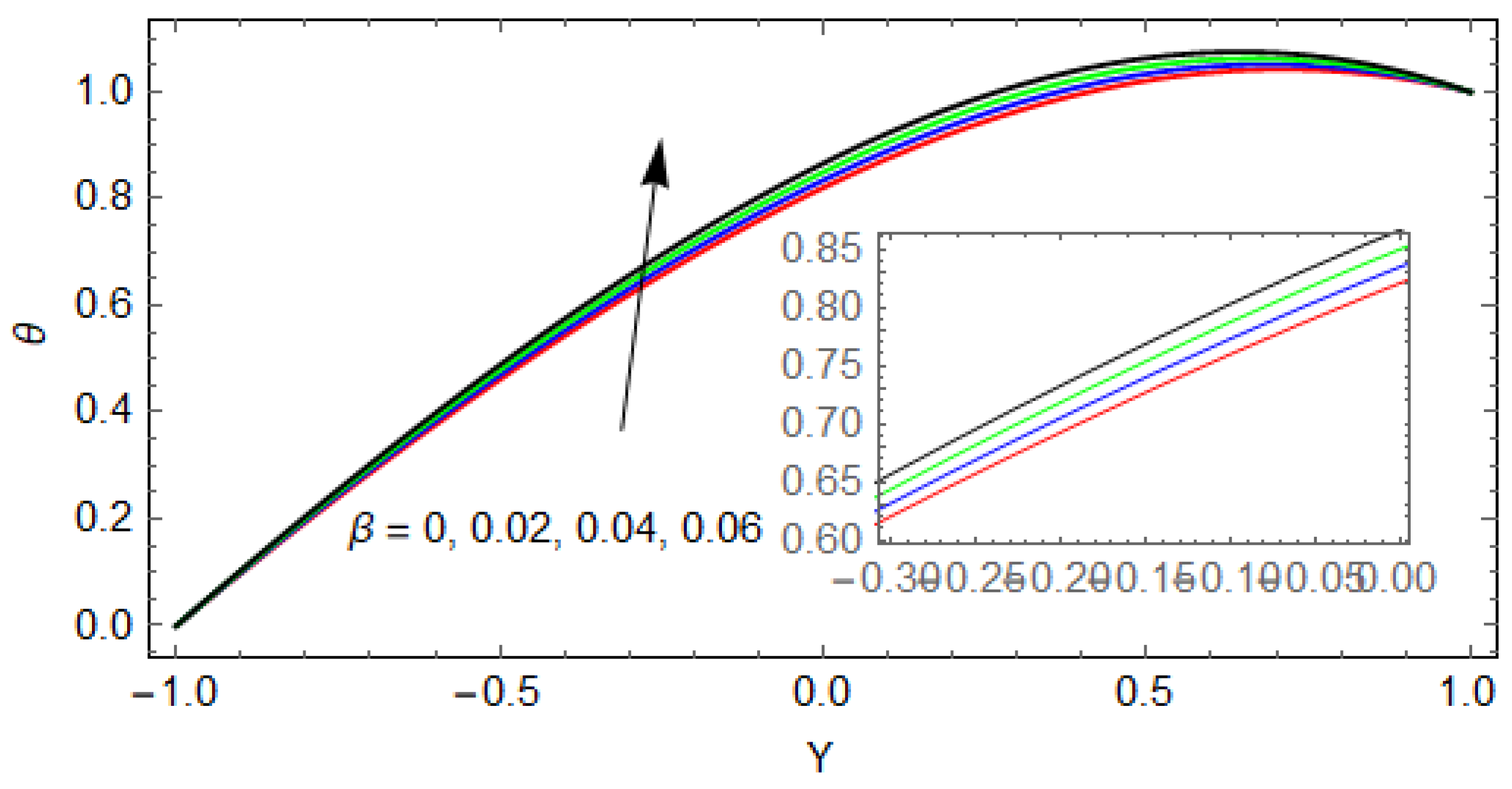
- The temperature profile decreases with increasing values of .
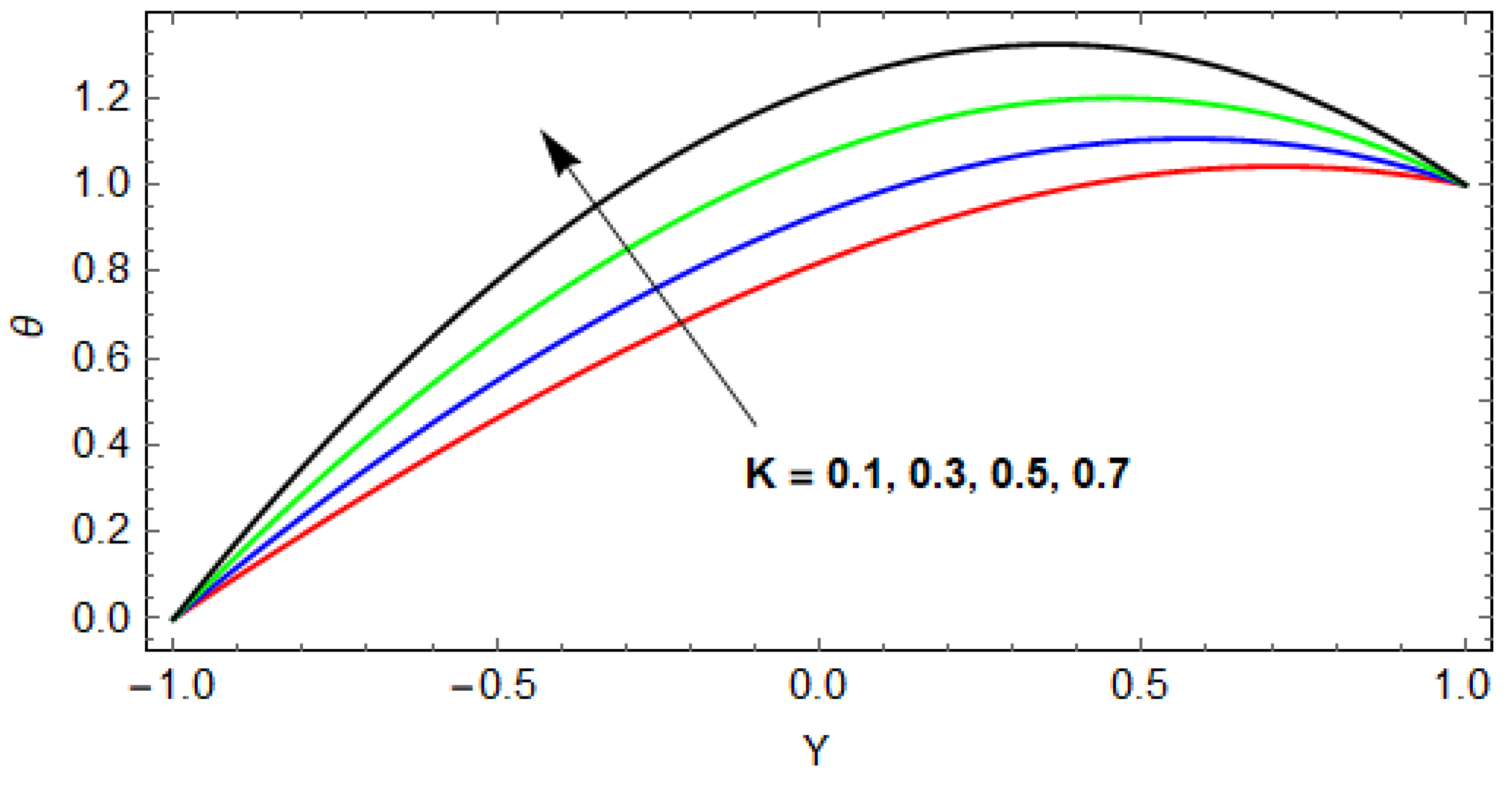
- The variation of the slip parameter and velocity ratio increase the temperature.
- The flow rate decreases compared to the Newtonian case for the variation of the couple stress parameter , which results in decreasing the coating thickness.
- The flow rate is maximum for the no slip condition and starts increasing when the value of increases. Hence, the coating thickness is a decreasing function of the slip parameter.
- At , and for the numerical results of flow rate are recovered and matched with Greener and Middleman [20].
Author Contributions
Funding
Institutional Review Board Statement
Informed Consent Statement
Data Availability Statement
Conflicts of Interest
References
- Booth, G.L. The Science and Technology of Polymer Films; Sweeting, O., Ed.; Interscience: New York, NY, USA, 1968; Volume 1. [Google Scholar]
- Balzarotti, F.; Rosen, M. Systematic study of coating systems with two rotating rolls. Lat. Am. Appl. Res. 2009, 39, 99–104. [Google Scholar]
- Zahid, M.; Zafar, M.; Rana, M.A.; Lodhi, M.S.; Awan, A.S.; Ahmad, B. Mathematical analysis of a non-Newtonian polymer in the forward roll coating process. J. Polym. Eng. 2020, 40, 703–712. [Google Scholar] [CrossRef]
- Belblidia, F.; Tamaddon-Jahromi, H.R.; Echendu, S.O.S.; Webster, M.F. Reverse roll-coating flow: A computational investigation towards high-speed defect free coating. Mech. Time Depend. Mater. 2013, 17, 557–579. [Google Scholar] [CrossRef]
- Zheng, G.; Wachter, F.; Al-Zoubi, A.; Durst, F.; Taemmerich, R.; Stietenroth, M.; Pircher, P. Computations of coating windows for reverse roll coating of liquid films. J. Coat. Technol. Res. 2020, 17, 897–910. [Google Scholar] [CrossRef]
- Benkreira, H.; Edwards, M.; Wilkinson, W. A semi-empirical model of the forward roll coating flow of Newtonian fluids. Chem. Eng. Sci. 1981, 36, 423–427. [Google Scholar] [CrossRef]
- Hao, Y.; Haber, S. Reverse roll coating flow. Int. J. Numer. Methods Fluids 1999, 30, 635–652. [Google Scholar] [CrossRef]
- Greener, J.; Sullivan, T.; Turner, B.; Middleman, S. Ribbing instability of a two-roll coater: Newtonian fluids. Chem. Eng. Commun. 1980, 5, 73–83. [Google Scholar] [CrossRef]
- Coyle, D.J.; Macosko, C.W.; Scriven, L.E. Stability of symmetric film-splitting between counter-rotating cylinders. J. Fluid Mech. 1990, 216, 437–458. [Google Scholar] [CrossRef]
- Chandio, M.; Webster, M. Numerical study of transient instabilities in reverse-roller coating flows. Int. J. Numer. Methods Heat Fluid Flow 2002, 12, 375–403. [Google Scholar] [CrossRef] [Green Version]
- Coyle, D.J.; Macosko, C.W.; Scriven, L.E. The fluid dynamics of reverse roll coating. Aiche J. 1990, 36, 161–174. [Google Scholar] [CrossRef]
- Jang, J.Y.; Chen, P.Y. Reverse roll coating flow with non-Newtonian fluids. Commun. Comput. Phys. 2009, 6, 536–552. [Google Scholar]
- Greener, Y.; Middleman, S. A theory of roll coating of viscous and viscoelastic fluid. Polym. Eng. Sci. 1975, 15, 1–10. [Google Scholar] [CrossRef]
- Middleman, S. Fundamentals of Polymer Processing; McGraw-Hill: New York, NY, USA, 1977; pp. 202–212. [Google Scholar]
- Kistler, S.F.; Schweiz, P.M. Liquid Film Coating–Scientific Principles and Their Technological Implications; Springer Science + Business Media: Dordrecht, The Netherlands, 1997. [Google Scholar]
- Carvalho, M.S.; Scriven, L.E. Deformable roll coating flows: Steady state and linear perturbation analysis. J. Fluid Mech. 1997, 339, 143–172. [Google Scholar] [CrossRef]
- Coyle, D.J.; Macosko, C.W.; Scriven, L.E. Film-splitting flows in forward roll coating. J. Fluid Mech. 1986, 171, 183–207. [Google Scholar] [CrossRef]
- Taylor, J.; Zettlemoyer, A. Hypothesis on the mechanism of ink splitting during printing. TappiJ 1958, 12, 749–757. [Google Scholar]
- Greener, J.; Middleman, S. Reverse roll coating of viscous and viscoelastic liquids. Ind. Eng. Chem. Fundam. 1981, 20, 63–66. [Google Scholar] [CrossRef]
- Sajid, M.; Mughees, M.; Ali, N.; Shahzad, H. Theoretical analysis of blade coating using third grade fluid. J. Plast Film. Sheeting 2019, 35, 218–238. [Google Scholar] [CrossRef]
- Sajid, M.; Shahzad, H.; Mughees, M.; Ali, N. Mathematical modeling of slip and magnetohydrodynamics effects in blade coating. J. Plast. Film Sheeting 2019, 35, 9–21. [Google Scholar] [CrossRef]
- Shahzad, H.; Wang, X.; Mughees, M.; Sajid, M.; Ali, N. A mathematical analysis for the blade coating process of Oldroyd 4-constant fluid. J. Polym. Eng. 2019, 39, 852–860. [Google Scholar] [CrossRef]
- Wang, X.; Shahzad, H.; Chen, Y.; Kanwal, M.; Ullah, Z. Mathematical modelling for flexible blade coater with magnetohydrodynamic and slip effects in blade coating process. J. Plast. Film Sheeting 2020, 36, 38–54. [Google Scholar] [CrossRef]
- Kanwal, M.; Wang, X.; Shahzad, H.; Chen, Y.; Chai, H. Blade coating analysis of viscous nanofluid having Cu–water nanoparticles using flexible blade coater. J. Plast. Film Sheeting 2020, 36, 348–367. [Google Scholar] [CrossRef]
- Kanwal, M.; Wang, X.; Shahzad, H.; Chen, Y.; Sajid, M. Mathematical modeling of micropolar fluid in blade coating using lubrication theory. SN Appl. Sci. 2020, 2, 1–8. [Google Scholar] [CrossRef] [Green Version]
- Kanwal, M.; Wang, X.; Shahzad, H.; Sajid, M.; Yiqi, C. Mathematical modeling of Johnson-Segalman fluid in blade coating process. J. Plast. Film Sheeting 2021, 1–27. [Google Scholar] [CrossRef]
- Taylor, G.I. The Scientific Papers of Sir Geoffrey, 1st ed.; Ingram Taylor on Scraping Viscous Fluid from a Plane Surface; Cambridge University Press: Cambridge, UK, 1971; pp. 410–413. [Google Scholar]
- Gaskell, P.H.; Summers, J.L.; Thompson, H.M. Creeping flow analyses of free surface cavity flows. Theor. Comput. Fluid Dyn. 1996, 8, 415–433. [Google Scholar] [CrossRef]
- Romanò, F.; Türkbay, T.; Kuhlmann, H.C. Lagrangian chaos in steady three-dimensional lid-driven cavity flow. Chaos Interdiscip. J. Nonlinear Sci. 2020, 30, 073121. [Google Scholar] [CrossRef]
- Romanò, F.; Suresh, V.; Galie, P.A.; Grotberg, J. Peristaltic flow in the glymphatic system. Sci. Rep. 2020, 10, 1–17. [Google Scholar] [CrossRef]
- Wahba, E. Multiplicity of states for two-sided and four-sided lid driven cavity flows. Comput. Fluids 2009, 38, 247–253. [Google Scholar] [CrossRef]
- Romanò, F.; Albensoeder, S.; Kuhlmann, H.C. Topology of three-dimensional steady cellular flow in a two-sided anti-parallel lid-driven cavity. J. Fluid Mech. 2017, 826, 302–334. [Google Scholar] [CrossRef]
- Stokes, V.K. Couple stresses in fluids. Phys. Fluids 1966, 9, 1709. [Google Scholar] [CrossRef]
- Sarangi, M.; Majumdar, B.C.; Sekhar, A.S. Elastohydrodynamically lubricated ball bearings with couple-stress fluids, Part I: Steady-state analysis. Tribol. Trans. 2005, 48, 404–414. [Google Scholar] [CrossRef]
- Saini, P.K.; Kumar, P.; Tondon, P. Thermal elastohydrodynamic lubrication characteristics of couple stress fluids in roll-ing/sliding line contacts. J. Eng. Tribol. 2007, 221, 141–153. [Google Scholar]
- Ali, N.; Sajid, M.; Abbas, Z.; Bég, O. Swimming of micro-organism in a fluid with couple stresses—A rheological model of em-bryological hydrodynamic propulsion. J. Mech. Med. Biol. 2017, 3, 1750054. [Google Scholar] [CrossRef]
- Javed, M.A.; Ali, N.; Sajid, M. Analysis of couple stress fluid in helical screw rheometer. IJST 2015, 39A4, 551–558. [Google Scholar]
- Mughees, M.; Sajid, M.; Ali, N.; Shahzad, H. Nonisothermal analysis of a couple stress fluid in blade coating process. Polym. Eng. Sci. 2020, 60, 1129–1137. [Google Scholar] [CrossRef]
- Ali, N.; Javed, M.A.; Atif, H.M. Non-isothermal analysis of calendering using couple stress fluid. J. Plast. Film Sheeting 2018, 34, 358–381. [Google Scholar] [CrossRef]
- Ali, N.; Atif, H.M.; Javed, M.A.; Sajid, M. A theoretical analysis of roll-over-web coating of couple stress fluid. J. Plast. Film Sheeting 2018, 34, 43–59. [Google Scholar] [CrossRef] [Green Version]
- Ali, F.; Hou, Y.; Zahid, M.; Rana, M.A. Theoretical study of the reverse roll coating of non-isothermal magnetohydrodynamics viscoplastic fluid. Coatings 2020, 10, 940. [Google Scholar] [CrossRef]
- Ali, F.; Hou, Y.; Zahid, M.; Rana, M. Mathematical analysis of pseudoplastic polymers during reverse roll-coating. Polymers 2020, 12, 2285. [Google Scholar] [CrossRef]


| 1 | 0.514336 | 0.534732 | 2.15734 |
| 2 | 0.533152 | 0.607919 | 2.23261 |
| 3 | 0.541463 | 0.637576 | 2.26585 |
| 4 | 0.545322 | 0.650887 | 2.28129 |
| Newtonian | 0.551585 | 0.671931 | 2.30654 |
| 1 | 0.508474 | 0.510223 | 2.13429 |
| 2 | 0.530000 | 0.596284 | 2.22000 |
| 3 | 0.538869 | 0.628468 | 2.25547 |
| 4 | 0.542939 | 0.642698 | 2.27175 |
| 5 | 0.545073 | 0.650037 | 2.28029 |
| 0 | 0.533152 | 0.607919 | 2.23261 |
| 0.01 | 0.531608 | 0.602246 | 2.22643 |
| 0.02 | 0.530000 | 0.596284 | 2.22000 |
| 0.04 | 0.526470 | 0.583363 | 2.20628 |
| 0.06 | 0.522807 | 0.568845 | 2.19123 |
| 0.08 | 0.518630 | 0.552288 | 2.17452 |
Publisher’s Note: MDPI stays neutral with regard to jurisdictional claims in published maps and institutional affiliations. |
© 2021 by the authors. Licensee MDPI, Basel, Switzerland. This article is an open access article distributed under the terms and conditions of the Creative Commons Attribution (CC BY) license (https://creativecommons.org/licenses/by/4.0/).
Share and Cite
Shahzad, H.; Wang, X.; Hafeez, M.B.; Shah, Z.; Alshehri, A.M. Study of Slip Effects in Reverse Roll Coating Process Using Non-Isothermal Couple Stress Fluid. Coatings 2021, 11, 1249. https://doi.org/10.3390/coatings11101249
Shahzad H, Wang X, Hafeez MB, Shah Z, Alshehri AM. Study of Slip Effects in Reverse Roll Coating Process Using Non-Isothermal Couple Stress Fluid. Coatings. 2021; 11(10):1249. https://doi.org/10.3390/coatings11101249
Chicago/Turabian StyleShahzad, Hasan, Xinhua Wang, Muhammad Bilal Hafeez, Zahir Shah, and Ahmed Mohammed Alshehri. 2021. "Study of Slip Effects in Reverse Roll Coating Process Using Non-Isothermal Couple Stress Fluid" Coatings 11, no. 10: 1249. https://doi.org/10.3390/coatings11101249
APA StyleShahzad, H., Wang, X., Hafeez, M. B., Shah, Z., & Alshehri, A. M. (2021). Study of Slip Effects in Reverse Roll Coating Process Using Non-Isothermal Couple Stress Fluid. Coatings, 11(10), 1249. https://doi.org/10.3390/coatings11101249