1. Introduction
Thermal barrier coatings (TBCs) are widely applied in aerospace engineering to protect metallic substrates and other engine parts from high-temperature exposure. In the 7YSZ (7–8% yttria-stabilized zirconia) layer, two techniques—generation of lamellar and columnar structure—can be used to develop a TBC. Atmospheric plasma spraying (APS) coating is widely formed via a plasma jet, and the particle is spread in the lamellar microstructure. It is sensitive to thermal mismatch between ceramic and substrate. Electron beam–physical vapor deposition (EB-PVD) coating exhibits strain tolerance owing to its columnar structure. Recently, suspension plasma spraying (SPS) was used to produce a structure similar to that produced via EB-PVD. Hence, in this study, we focus on SPS, which possesses the advantage of EB-PVD and APS.
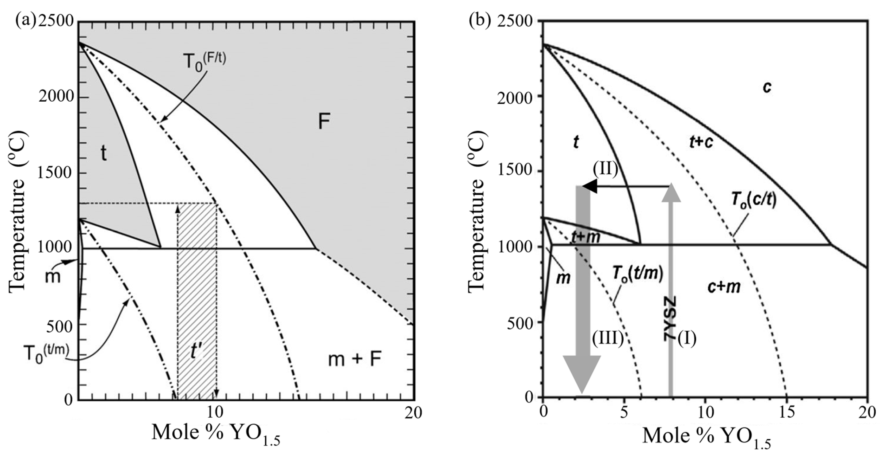
The main difference between pure zirconia and YSZ corresponds to the phase composition, and the metastable phase diagram of YSZ is shown in
Figure 1a [
1].
and
denote the transition temperature of the tetragonal-to-monoclinic phase and the cubic-to-tetragonal phase, respectively. Undoped zirconia is characterized as an unstable material. When the temperature is under 1114 °C, zirconia exists in the monoclinic phase. When the temperature is between 1114 °C and 2369 °C, a phase transformation occurs, which leads to a stable phase, and the phase adapts to a cubic structure when the temperature exceeds 2369 °C. However, the phase transformation from the tetragonal-to-monoclinic phase during the cooling procedure [
2] leads to volume expansion of 5%. This, in turn, results in a driving force that leads to microcrack propagation and interfacial delamination. Hence, many researchers focused on the stabilization of the tetragonal phase by adding oxides, such as yttria (Y
2O
3) and ceria (Ce
2O), which exhibit a cation radius similar to that of zirconium. The main aim of the stabilization is to prevent 5% volume expansion due to the martensitic transformation during cooling. Herein, the t’ phase that can exhibit the best performance can be realized via yttria doping in the range of 7–8 wt.% (approximately 4.5 mol.%), as shown in
Figure 1a by the hashed area. The t’ phase cannot transform into a monoclinic phase upon cooling, and it is often referred to as the non-transformable tetragonal phase [
3].
Aircraft engines encounter particulate debris in atmosphere and volcanic ash at cruise altitude. Typically, volcanic ash consists of harmful mineral particulates, such as Al
2O
3, CaO, SiO
2, MgO, and Fe
2O
3, which are often referred to as calcium–magnesium–alumino-silicates (CMAS). Thermochemical and mechanical properties of Eyjafjallajökull volcanic ash were studied by Webster et al. [
4]. The thermochemical and mechanical reaction of CMAS can dramatically promote the destabilization of YSZ [
5]. Phase transformation would occur, and the content of the zirconium and yttrium elements decreases with the evaporation of ZrO
2 and Y
2O
3 during the supersonic atmospheric plasma spraying process [
6]. The original YSZ is composed of 8 wt.% of Y
2O
3 as a phase stabilizer, and the effects of thermal exposure due to volcanic ash were examined on the original YSZ. After 10 h of thermal exposure, only 3.71 wt.% of Y
2O
3 was observed in the top region of YSZ. This indicated destabilization due to the molten volcanic ash that infiltrates the YSZ top region via chemical reaction: yttria is depleted by CMAS.
Figure 1b introduces the process wherein YSZ is attacked by CMAS. Specifically, arrow (I) indicates that the non-transformable tetragonal phase is maintained in the stable tetragonal phase during heating. Further, arrow (II) indicates Y depletion due to the interaction between YSZ and CMAS at high temperatures. The melting CMAS dissolves the non-transformable tetragonal phase and extracts the yttrium from stabilized zirconia. This denotes that the grain boundary of zirconia becomes unstable because of the Y depletion region induced by CMAS infiltration [
7]. Finally, the monoclinic phase is formed, given that arrow (III) denotes interaction with
during cooling to room temperature, as shown in
Figure 1b. The results of Raman spectra [
8] indicated that the 7YSZ sample with CMAS exhibits characteristic peaks related to the monoclinic phase at approximately 600 °C during cooling.
The failure analysis in YSZ TBCs induced by CMAS infiltration has been investigated by several researchers. The degradation of EB-PVD TBCs due to the attack by CMAS deposits was examined by Peng et al. [
9]. Based on the CMAS infiltration, the YSZ topcoat can be classified into two different layers: a CMAS-rich layer and a non-infiltration layer (original 7YSZ) [
10]. During the thermal cycle, the CMAS-rich layer becomes denser and exhibits a higher thermal mismatch with the substrate. Based on thermodynamic laws and a mechanism-based constitutive theory, a couple of chemo-thermo-mechanical constitutive theories for TBCs under CMAS infiltration were reported by Xu et al. [
11]. The buckling phenomenon in YSZ TBCs induced by CMAS was investigated by Shan et al. [
12]. They discussed the significant volume expansion in the topcoat induced by CMAS infiltration. Based on the volume changes and phase transformation, the delamination and buckling of thin layers bonded to soft substrates were proposed by Reinoso et al. [
13]. Li et al. discussed the temperature and stress fields in TBCs exposed to CMAS infiltration via experiment and simulation [
14]. For the failure behavior of the coating system by the experiment and numerical method, the chemo-mechanical damage model on polycrystalline materials between mechanics and species diffusion was studied by Bai et al. [
15]. Using the cohesive element method, Rezaei et al. [
16,
17] predicted the failure behavior and crack propagation of the coating system problem. Zhang et al. [
18] conducted a numerical analysis and obtained the transient thermal stress in EB-PVD TBCs due to CMAS penetration. Dynamic CMAS infiltration failure analysis in TBCs was calculated by Tseng et al. [
19]. Su et al. [
20] numerically analyzed interfacial delamination in TBCs induced via CMAS infiltration. Naraparaju et al. [
21] established a new model for estimating the CMAS infiltration depth in TBCs. The numerical study considering fluid–solid interactions between the CMAS and the topcoat was performed by Kabir et al. [
22].
Generally, the failure due to expansion in TBCs induced by CMAS infiltration has not been clearly understood. Therefore, the objective of this study involves investigating the buckling mechanism and interfacial stress evolution of SPS TBCs induced via CMAS infiltration. In this study, the evolution of residual stress due to expansion via CMAS infiltration in TBCs is discussed using experiments and simulations. In the first part, a free-standing YSZ covered by CMAS is examined via experiments. Then, a simulation model of a double-cantilever beam is established with the experimental approach. Finally, the residual interfacial stress of TBCs is determined using the corresponding multilayer cantilever beam model.
3. Numerical Method
To investigate the infiltration process and interfacial stress evolution, two types of infiltrated coating models were used in this study, as shown in
Figure 4. In
Figure 4a, type I corresponds to a free-standing model, which is embedded by CMAS. The free-standing model was provided to confirm that the simulation and experimental results of the buckle height were in good agreement. The depth of the topcoat
HTC was 0.2 mm. Notably, the depth
of the CMAS-rich layer was defined by the experimental results via Equation (1). The depth
of the infiltrated region was calculated by the simulation method, which will be introduced in
Section 3.2. Furthermore, the depth
of the CMAS-rich layer included the depth of the topcoat. Type II corresponds to the TBC model and includes the topcoat, bond coat, and substrate, as shown in
Figure 4b. The depths of topcoat
HTC, bond coat
HBC, and substrate
HSUB were assumed as 0.2, 0.1, and 2 mm [
26], respectively. Actually, the simulation result of interfacial stress showed the same value via different widths of the coating system,
w (3.5 mm, 5 mm, 6.5 mm), which means that the width of the coating system does not generate the boundary effect. Hence, the width of the coating system,
w, was set at 3.5 mm owing to saving computational efficiency. This model was established to examine the interfacial stress distribution of SPS TBCs due to CMAS infiltrating. The finite element models were constructed using the mesh with almost 45,000 elements and 414,000 elements for type I and type II models, respectively. All of the meshes were four-node quadrilateral elements (DC2D4 in the heat transfer analysis and CPE4T in the thermal structure analysis) for the topcoat, bond coat, and substrate.
To observe the buckle height behavior induced via CMAS infiltrating, the displacement was set to zero in the vertical direction at point A, while the bottom edge was fixed in the vertical direction to simulate the realistic service conditions, as shown in
Figure 4. The left edge was assumed symmetric to simplify calculation processing, and the right edge was assumed with a traction-free condition. To confirm the agreement between the simulation and experimental results, heating was performed in the model from room temperature to holding temperature (25–1400 °C) at a heating rate of 5 °C/min. Subsequently, different holding times of 4, 6, 8, 10, and 12 h were introduced into the model. Specifically, the model was infiltrated with CMAS during this period. Finally, the environment in the model was cooled to room temperature at a cooling rate of 5 °C/min.
3.1. Material Properties
In the study, the material properties of TBCs, including Young’s modulus
E, Poisson’s ratio
ν, heat conductivity
k, and coefficient of thermal expansion
α, were used to characterize the elastic behavior of the TBCs, as listed in
Table 1.
The effect of CMAS infiltration on the SPS coating is critical because it increases the driving force for interfacial delamination. However, it is difficult to measure the elastic and thermal properties of the compound of CMAS and the topcoat at service temperature via experiments. The structure of an infiltrated topcoat can be modeled as a laminate with the topcoat and CMAS phase. The elastic modulus of the compound can be determined by the Reuss rule-of-mixtures [
27] as follows:
where
denotes the effective elastic modulus of the SPS with CMAS. Additionally,
and
denote the elastic modulus of dense t’-YSZ and CMAS, respectively;
denotes the volume fraction of the SPS coating, which is set at 90%; and
denotes
, which is set at 10%. In the case of the non-infiltrated topcoat, the effective Young’s modulus is defined as 40 GPa [
28]. The results indicated that the effective Young’s modulus shows agreement between the experiment and the Reuss method. If the pores in the topcoat are filled with CMAS, the topcoat becomes a dense t’-YSZ with
= 200 GPa [
29]. Given the stiffened mechanism due to the infiltration of CMAS, the effective Young’s modulus of the topcoat significantly increased from 40 to 175 GPa (non-infiltration to infiltration), as listed in
Table 1. Notably, the effective Young’s modulus of the CMAS-rich layer is similar to the value evaluated via object-oriented finite elements [
31]. Jackson et al. [
27] also indicated that the effective modulus of the CMAS-rich layer increases to 180 GPa when the silicates crystallize and stiffen.
The thermal expansion coefficient of the infiltrated topcoat can be calculated via the Schapery rule-of-mixtures [
32] as follows:
Specifically, the coefficient of thermal expansion of CMAS ranged from 7–9 °C
−1. Additionally,
was selected as
°C
−1 in this analysis, and
denoted that the effective coefficient of thermal expansion from 11
°C
−1 to 10.87
°C
−1 (non-infiltration to infiltration), as listed in
Table 1.
3.2. Expansion Induced by CMAS Infiltration
Based on our experimental results, the depth of the CMAS-rich layer can be modeled based on Equation (1). During CMAS infiltration, YSZ can be separated into a CMAS-rich layer and a non-infiltration region. Based on the element-change method USDFLD, the element properties of the topcoat are immediately transferred from the non-infiltration to the infiltration region based on Equation (1). Furthermore, experimental observations indicate that the volume of the infiltrated region is significantly affected by the separation of grain boundaries, dissolution of YSZ into CMAS, sintering of YSZ, and crystallization of molten CMAS. However, it is difficult to precisely determine the increase in the volume of the reaction region induced by CMAS infiltration at elevated temperatures. In previous studies related to the expansion model, Shaw and Duncombe [
33] concluded a linear expansion at a constant rate at the beginning of the infiltration. Hence, the expansion decelerates and reaches a plateau. This denotes that equilibrium is realized with respect to expansion after the plateauing time. The depth
of the infiltrated region can be expressed in terms of the depth
of the CMAS-rich layer obtained via experiments and expansion due to CMAS infiltration, which can be related to the period of holding time. Specifically, the depth of the infiltrated region exhibits a square-root behavior as a function of the holding time as follows:
where A denotes the pre-exponential factor.
The thickening rate of the element row at the edge of right side,
, is as follows:
The growth strain rate of the edge of right side,
, is defined as follows:
The expansion in the reaction region is implemented via the subroutine UEXPAN in ABAQUS. It should be noted that expansion via CMAS infiltration provides the material behavior during the holding time for both the type I and type II models in the thermal structure analysis. The expansion strain increments of the reaction region are defined as isotropic swelling, which indicates that the element of the reaction region equally swells along the thickening and lateral directions with respect to a time increment. Conversely, the element transfers the properties by USDFLD and swells along the thickening and lateral directions when the YSZ corresponds to the reaction region based on Equation (6).
3.3. Expansion Induced via Phase Transformation
During the cooling stage, the phase transformation plays a crucial role in the thermomechanical failure induced via CMAS infiltration in 7YSZ TBCs. The experimental results indicated [
6] that YSZ lacks Y
3+ cations. This can lead to tetragonal–monoclinic transformation at the approximate range of 300–900 °C. This is dependent on the amount of yttrium oxide remaining in zirconia. Yashima et al. [
3] examined the metastable–stable phase diagrams in the zirconia–yttrium system. The transition temperature
is thermodynamically defined as the temperature where the free energies of monoclinic and tetragonal phases are equal. It is determined via experiments as follows:
where
x denotes the concentration of Y
2O
3 in mole percent. It is difficult to obtain the transition temperature
, because the temperature is dependent on the microstructure of yttria-stabilized zirconia, heat treatment, and stress distribution. In the study, the range of transition temperature
was assumed to be 600–500 °C, which indicates that the range of the concentration of Y
2O
3 was approximately 3.2–3.8%. It can be considered that the phase transformation started from 600 °C and was completed at 500 °C during the cooling process in the CMAS-rich layer. The phase transformation significantly affects the volume change, which corresponds to an increase of approximately 5%. In our simulation, the expansion was applied to implement the phase transformation process. Herein, the finite element model was considered for a 2-dimensional condition. Thus, the expansion value could be modified from volume to area. Hence, the value of the expansion area could be solved, and it corresponded to an increase of approximately 3%. Thus, the simulation forcibly satisfies the condition that the reaction region increases in the area by 3% when the temperature reaches the t-to-m martensitic transition temperature during the cooling stage. It should be noted that expansion via phase transformation provides the material behavior during the cooling time for both the type I and type II models in the thermal structure analysis. The increment in all the expansion strains can be implemented by UEXPAN and includes the thermal expansion strain, the expansion strain induced by CMAS infiltration, and the expansion strain due to transformation.
4. Numerical Result
Initially, it is necessary to clarify certain parameters between the simulation and the experiment. There are two major expansion factors for the CMAS-rich layer in the simulation and experimental processes. One of the factors is produced due to the separation of grain boundaries at high temperatures, and the other factor is associated with expansion induced by martensitic transformation during cooling. The latter is assumed to be 3% due to the modification from volumetric expansion (5%) to area expansion (3%) during the comparison between the simulation and experimental results of the buckle height. Based on Equation (6), the pre-exponential factor A must be determined to ensure agreement between the simulation and experimental results of the buckle height.
Figure 5 shows that the buckle height was obtained via experimental and simulation results with different pre-factors. In
Figure 5, solid dots and lines denote the experimental data and simulation data, respectively. In this case, the expansion rate was assumed to be 3%. A different pre-factor was selected in the simulation. The results show that increases in A indicate the occurrence of a more severe situation of grain boundary separation at high temperatures. This in turn generates a more critical buckle condition. Conversely, when A corresponds to zero, it indicates that the expansion does not occur during CMAS infiltration at high temperatures, and the buckle height value is restricted. Hence, it is concluded that pre-factor A can be defined as 0.0014 to obtain an identical buckle height value in the simulation and experiment.
Based on the aforementioned assumptions, the figure of the experiment and simulation of the buckle height induced by the infiltration of CMAS is listed in
Table 2. The experimental and simulation results of YSZ induced by CMAS at room temperature for holding time values of 4 h, 8 h, and 12 h are shown in
Table 2. The results suggest that the simulation solutions are in good agreement with the corresponding experimental results in terms of the buckle height of the YSZ specimens induced by CMAS infiltration.
The manner in which the two major expansion factors affect the buckle height is interesting.
Figure 6 shows the buckle height of YSZ induced by CMAS infiltration with different expansion rates where the holding time is 12 h and pre-factor A is assumed to be 0.0014 in Equation (6). In this case, a thermal cycle, including heating, holding, and cooling process, is determined. During heating, the buckle height is maintained at zero because the specimen can be considered a free expansion with no CMAS infiltration. Further, the parabolic behavior of the buckle height is exhibited during the holding time. At high temperatures, CMAS gradually infiltrates YSZ specimens, and the CMAS separates the grain boundaries. Specifically, the dissolution and reprecipitation of zirconia grains occur, and the yttria-depleted zirconia phase is gradually formed. In the metastable zirconia–yttria phase diagram, arrow (II) denotes the CMAS infiltration during the holding time, as shown in
Figure 1b. Additionally, the slope of the buckle height gradually decreases with respect to the depth of the CMAS-rich layer. The growth in the strain rate exhibits a parabolic behavior in the holding stage. The yttria-depleted zirconia phase (CMAS-rich layer) transforms from a tetragonal to a monoclinic phase during cooling. Arrow (III) denotes the interaction with the T
0 curve during the cooling process, as shown in
Figure 1b, and thus the high expansion of the CMAS-rich layer transforms to the monoclinic phase. If transformation is absent, the A–a line denotes the evolution of the buckle height during the cooling time, as shown in
Figure 6. To simplify the expansion process induced via phase transformation, 600 °C and 500 °C are assumed to be the start and final times of the phase transformation. Points B and C indicate the value of the buckle height with an expansion rate of 1.5% and 3%, respectively, at a temperature of 500 °C. Hence, the B–b line and the C–c line can be considered the evolution of the buckle height with expansion rates of 1.5% and 3%, respectively, during cooling. Evidently, the buckling behavior is more harmful when the expansion rate increases, as shown in
Figure 6.
The buckle height for different holding times was investigated with respect to three different expansion rates, as shown in
Figure 7. In this case, the value of the buckle height was selected at room temperature, and points a, b, and c were selected, as shown in
Figure 6. It should be noted that different holding times of 4, 6, 8, 10, and 12 h were implemented into the type I model. In this investigation, the expansion via phase transformation was more severe when the expansion ratio was 3%. On the contrary, the expansion ratio of 0% represents that phase transformation will not occur during the cooling step. The results indicate that the expansion rate significantly affects the value of the buckle height. When the expansion rate via phase transformation increases during the cooling stage, buckling is more dangerous. As expected, the value of the buckle height increases when the time of the free-standing YSZ infiltrated by CMAS is operated at high temperatures for a long time. This occurs because the depth of the CMAS-rich layer is deeper, and expansion due to the separation of grain boundaries and martensitic transformation is more significant.
In the second step, the residual interfacial stresses were determined at room temperature. Hence, the corresponding value, which includes expansion due to CMAS infiltration during the holding time and phase transformation during the cooling time, would transfer from the type I to the type II model. It includes the topcoat, bond coat, and substrate, as shown in
Figure 4b. The maximum interfacial normal and shear stresses between topcoat and bond coat are shown in
Figure 8a,b, respectively. This indicates that both interfacial normal and shear stresses are significantly affected by the phase transformation and the period of the holding time. As we know, the infiltrated region is deeper when the holding time is longer. In addition, the value of the buckle height increases when the TBCs infiltrated by the CMAS last for a long time. It can be observed that the interfacial stresses heightened owing to a larger expansion ratio and holding time. It can be speculated that increasing the expansion ratio via phase transformation and holding time would enhance the driving force for the crack evolution and interfacial delamination of the TBCs infiltrated by CMAS. This calculation indicates that the interfacial normal and shear stresses obtained via the phase transformation model are 27% higher than those obtained with the model without phase transformation. Additionally, the interfacial shear stress is more dominant than the interfacial normal stress. Previous studies [
7] indicate that volume change can correspond to an increase in shear stress, which is as high as 10% and can fail the coating via spallation. Hence, the result of interfacial stress indicates that the TBCs exhibit a high probability of occurrence of interfacial delamination induced by CMAS infiltration during cooling. Hence, the shear-direction interfacial stress due to expansion by martensite transformation dominates the damage mechanism.


