Article

Evaporated MoOx as General Back-Side Hole Collector for Solar Cells

Italian National Agency for New Technologies, Energy and Sustainable Economic Development (ENEA)—Portici Research Centre, Piazzale E. Fermi 1, 80055 Portici (Na), Italy
*
Author to whom correspondence should be addressed.
Coatings 2020, 10(8), 763; https://doi.org/10.3390/coatings10080763
Submission received: 30 June 2020 / Revised: 30 July 2020 / Accepted: 3 August 2020 / Published: 6 August 2020
(This article belongs to the Special Issue Advances in Thin Films for Photovoltaic Applications)

Abstract

:
Substoichiometric molybdenum oxide (MoOx) has good potential as a hole-collecting layer in solar cells. In this paper, we report on the application of ultrathin evaporated MoOx as a hole collector at the back side of two distinct photovoltaic technologies: polymeric and silicon heterojunction (SHJ). In the case of polymer solar cells, we test MoOx as a hole transport layer in devices with inverted architecture. The higher transparency of the MoOx film, compared to the commonly used poly(3,4-ethylenedioxythiophene):poly(styrenesulfonate) (PEDOT:PSS), allows an enhanced back reflected light into the photoactive layer, thus boosting the photogeneration, as found from the illuminated J-V and external quantum efficiency (EQE) curves. The higher fill factor (FF) of the MoOx-based device also suggests an improved charge collection efficiency compared to the cells with PEDOT:PSS. As for SHJ solar cells, we show that MoOx offers the means for dopant-free hole collection with both p-type and n-type Si wafers. In the present comparison over planar test structures with Ag back reflecting electrodes, we observe an efficiency gain of approximately 1% absolute against a baseline with a conventional p-type amorphous silicon hole collector. The gain is linked to the increased VOC, which is likely due to the reduced recombination at the Si wafer.

Graphical Abstract

1. Introduction

Transition metal oxides, and substoichiometric molybdenum oxide (MoOx, x < 3) in particular among them, have attracted considerable interest for application as a supportive layer for charge collection into solar cells of various technologies, from silicon-based to polymeric to the novel perovskite solar cells [1,2,3,4,5,6,7,8,9,10,11,12]. Solar cells fundamentally consist of a semiconductor light absorber equipped with selective contacts for charge-carrier separation and extraction, complemented by proper electrodes for external connection. Based on its high work function (up to 6.9 eV) and large bandgap (approximately 3 eV) [13], MoOx is an excellent candidate as a hole collector with potentially low optical losses independent of the specific photovoltaic technology.
Thermal evaporation is often used for the deposition of thin MoOx films, making it a viable and cost-effective choice. A drawback is the sensitivity of the material to air and moisture [14], which means that exposure to the environment should be avoided. The issue is emphasized with evaporated films due to their oxygen deficiency. However, oxygen vacancies are to some extent desired, since they enable the charge carrier transport [1].
The material has been more commonly proposed as a front side (illumination side) hole collector, to fully take advantage of its transparency. This type of application, although promising, may entail some technical difficulties for some device architectures. Often, a capping transparent conductive electrode, typically deposited by sputtering, is indeed needed, and it has been shown that Ar plasma exposure and transparent conducting oxide (TCO) overlayer deposition induce coloration of the material and then parasitic light absorption [3,15]. While countermeasures are under investigation [15], we here explore the application of the material as a rear side hole collector, where this issue can be avoided. In this case, the use of a TCO is not mandatory, and a full area metal electrode can be deposited over the MoOx layer. To demonstrate the wide applicability of the approach, we have here considered two distinct photovoltaic technologies: polymeric and silicon heterojunction (SHJ), where both the fabrication processes and the mechanisms behind the device operation are very different. We report on the application of evaporated MoOx layers to these types of solar cells and on the associated benefit.

1.1. Focus on Polymer Solar Cells

Polymer solar cells (PSCs) have attracted intensive investigation in the last three decades due to their potential advantages such as mechanical flexibility, light weight, large-area fabrication, and low manufacturing cost by using roll-to-roll printable techniques [16,17,18,19,20]. In order to compete with inorganic devices in the commercialization of real-world applications, high power conversion efficiency (PCE) and prolonged lifetime are of crucial importance. Recently, PCE higher than 18% [21] has been achieved for single-junction devices, but long stabilities are still an issue, although important progress has been recently achieved [22].
The typical PSC design (standard structure) consists of a transparent front electrode covered by a thin hole conducting layer, a photoactive layer (typically a blend of a semiconducting donor polymer and a fullerene derivative acceptor forming a bulk-heterojuncton (BHJ) [16]), an electron transport layer, and a rear metal contact. This structure suffers from device stability due to the deterioration of the metal contact (Ca/Al) and hole transport layer (HTL), which is usually poly(3,4-ethylenedioxythiophene):poly(styrenesulfonate) (PEDOT:PSS). The development of the so-called inverted device structure (i.e., a PSC where the polarity of the electrodes is reversed compared to the standard one) has contributed to significantly improving the lifetime of the devices [23,24].
In both the architectures, poly(3,4-ethylenedioxythiophene):poly(styrenesulfonate) (PEDOT:PSS) is the most common material used as an HTL. This material raises some concerns when applied into inverted PSCs. In particular, the processability of PEDOT:PSS (dispersion in water and post deposition annealing) limits its application due to deterioration of the underlying blend, since a lot of blend materials, used in devices with high PCE, suffer from humidity or annealing treatments. Thanks to their favorable optoelectronic properties, metal oxides (such as MoOx) have emerged as possible substitutes of PEDOT:PSS. Solution-processed MoOx has been successfully used as an HTL in both normal and inverted PSCs [25,26,27], although application in the inverted device is still a challenge due to processing issues (i.e., deterioration of the blend film). These issues could be avoided when applying thermally evaporated MoOx, which is a promising material as HTL in inverted PSC due to the favorable energy alignment between its work function and the HOMO level of the commonly used blends. For these reasons, we have investigated the use of thermally evaporated MoOx as an HTL in PSCs with inverted structure and compared their performance with reference devices employing PEDOT:PSS.

1.2. Focus on Silicon Heterojunction Solar Cells

SHJ solar cells are among the most efficient cells, with a record efficiency of 26.7% reached in the interdigitated back contact configuration [28]. Conversion efficiencies above 25% have been also demonstrated in the more conventional architecture featuring contacts on both the front and back sides [29], which is the design here considered. The device is based on a crystalline silicon (c-Si) wafer as a light absorber, which is passivated by ultrathin intrinsic hydrogenated amorphous silicon (a-Si:H) providing the chemical passivation of Si dangling bonds at the c-Si surface. Thin suitably doped silicon-based layers, mostly a-Si:H, nc-Si:H, or nc-SiOx:H, are applied as selective contacts (p-type doped films for hole collection and n-type for electron collection), where doping is used for shifting the Fermi level close to the valence or conduction band of the absorber, thus achieving hole or electron selectivity, respectively. In the top/rear contact design, the two films are separately deposited over the two passivated surfaces. Then, a TCO layer is applied as an antireflective front electrode, complemented by a metal grid, while the back side is covered by a full area metal-based electrode.
The doped layers are fabricated by plasma-enhanced chemical vapor deposition (PECVD) with a gas precursor mixture that includes toxic dopant gases. Doping of the thin film silicon layers requires delicate deposition optimizations and, especially with p-type doping, induces the formation of recombination-active defects. Thus, the possible substitution of these layers with dopant-free counterparts, in addition to fabrication by a simple low-cost technique such as thermal evaporation, is very attractive. In recent years, evaporated MoOx has been indeed proposed as an alternative hole collector in SHJ, with this layer applied at the front side of devices based on n-type c-Si wafers, obtaining conversion efficiencies up to 23.5% [7]. This is the most common configuration for this wafer type, which is also called front emitter configuration (minority carrier collector placed at the illuminated front side), where in principle, MoOx is advantageous also from the optical point of view if suitable measures are taken to avoid the mentioned deterioration of the material when applying the capping TCO.
As a complementary approach for SHJs with a dopant-free hole collector, we have explored the use of MoOx over the rear side. We propose the application of the layer to both n-type and p-type wafers, which are both interesting because the former have so far demonstrated the highest solar cell efficiencies and the latter are still the main choice of the PV manufacturing industry. With the commercially relevant p-type wafer, the implementation of MoOx at the rear side corresponds to the standard cell configuration, since the layer functions as a collector of majority carriers, while the n-type Si-based emitter layer is at the front side. Particularly interesting is the application of the MoOx layer at the rear of n-type wafers, as it makes also for an unconventional cell design, since MoOx functions as an emitter (minority carrier collector). This second configuration (rear emitter cell design) is in itself a promising concept that has recently been under thorough investigation, as it provides relaxed constraints on the optoelectronic properties of the front TCO [30,31,32].

2. Materials and Methods

2.1. Single-Layer Fabrication and Characterization

MoOx layers were deposited onto Eagle XG glass substrates for optical characterization. The amorphous MoOx layers were grown by the thermal evaporation of high-purity stoichiometric powder (99.95%) at a rate of 1 Å/s out of a tungsten boat at a base pressure below 4 × 10⁻⁷ mbar. During the evaporation process, no intentional heating was applied to the substrate, which remained close to ambient temperature. The thickness and optical constants of the samples were evaluated using a variable angle ellipsometer (VASE, J.A. Wollam Co., Lincoln, NE, USA) by acquiring data over three angles of incidence and complementing it with transmittance spectra measured on the same spot. The work function (WF) of the material evaporated on an n-type cSi substrate was measured using a SKP5050 Scanning Kelvin Probe system by KP Technology (Wick, UK) [33,34].

2.2. Device Fabrication

For the fabrication of the PSCs, we used the following structure: glass/ITO/ZnO/photoactive layer/HTL/Ag, where the photoactive layer is a BHJ of poly[4,8-bis(5-(2-ethylhexyl)thiophen-2-yl)benzo[1,2-b;4,5-b′]dithiophene-2,6-diyl-alt-(4-(2-ethylhexyl)-3-fluorothieno[3,4-b]thiophene-)-2-carboxylate-2-6-diyl)] (PTB7-Th) and [6,6]-phenyl C71 butyric acid methyl ester ([70]PCBM), and the HTL is MoOx or PEDOT:PSS. The ZnO precursor was prepared by the sol–gel process as described elsewhere [35]. The ZnO films (40 nm) were obtained by spin coating the solution at 4000 rpm for 60 s on top of patterned and cleaned glass/ITO substrates (Delta Technologies, sheet resistance of 10 Ω/square). The films were annealed at 150 °C for 5 min. The active layer (90 nm) was realized by dissolving PTB7-Th (Solarmer Inc., Irwindale, CA, USA, 15 mg/mL) and [70]PCBM (Solenne BV, Groningen, The Netherlands, 22.5 mg/mL) in a mixed solvent of 1,2-dichlorobenzene:1,8-diiodoctane (97%:3% by volume) and spin coated on top of the ITO/ZnO structure. A 5 nm MoOx layer and a 100 nm Ag layer were sequentially thermally evaporated, without breaking the vacuum, through a shadow mask to form a top anode. For the cells with PEDOT:PSS (Clevios AL 4083, Heraeus, Hanau, Germany), a 40 nm-thick layer was deposited as described elsewhere [36] before Ag deposition. The active area of the device was 22 mm2.
For the fabrication of Si heterojunction solar cells, we used flat float-zone c-Si <100> wafers, both p-type and n-type, with resistivity of 1–5 Ω·cm (Topsil GlobalWafers A/S, Frederikssund, Denmark). The fabrication sequence started with RCA cleaning of the Si wafers followed by native oxide removal through dipping into 2% HF solution. Then, the two wafer sides were passivated with 5 nm-thick intrinsic a-Si:H. Afterwards, the front side was covered with the electron collector, which is made of highly transparent n-type nanocrystalline silicon oxide (nc-SiOx:H) with a thickness of 20 nm, and the antireflective transparent front electrode, which is made of 80-nm sputtered ZnO:Al completed with an Al collection grid. The area of the solar cells was defined as 2 × 2 cm2 at the stage of the front electrode fabrication by using a shadow mask. The hole collector was applied to the back side. Two materials were considered in this case: 20 nm-thick conventional p-type a-Si:H and MoOx (10 nm-thick, unless otherwise stated). Finally, the back electrode was applied by evaporating a full area 100 nm-thick Ag film. For the cells with MoOx, the Ag cover layer was deposited without breaking the vacuum in the same deposition system. All the Si- and SiOx-based layers were deposited by plasma-enhanced chemical vapor deposition (PECVD) at standard frequency or a very high frequency regime at 40 MHz (the first for intrinsic and n-type films, and the second for the p-type layers) in an MVSystems Inc. cluster tool, using previously optimized parameters [37,38].

2.3. Device Characterization

The solar cells were characterized by measuring the current–voltage characteristics under AM1.5 illumination with class AAA solar simulators. For the SHJ cells, the simulated sunlight was provided by a dual-lamp WACOM simulator, and the measurements were carried out at standard condition, after adjustment of the total irradiance based on a c-Si reference cell. The PSCs were measured in a nitrogen-filled glove box (O2 and H2O < 1 ppm) at 25 °C with a Keithley 2400 source measure unit (Keithley Instruments Inc., Cleveland, OH, USA). Simulated AM1.5 illumination was provided by a Photo Emission Tech solar simulator (model CT100AAA), equipped with a 150 W Xenon lamp, whose intensity was calibrated using a c-Si reference cell with a KG5 filter for 1 sunlight intensity of 100 mW/cm2. Dark I-V curves were also measured with a Keithley 2400 source measure unit. The external quantum efficiency (EQE) spectra were measured with a Bentham PVE300 apparatus calibrated with an Si detector.

3. Results and Discussion

3.1. Properties of MoOx Films

MoOx layers deposited on glass were characterized with spectroscopic ellipsometry (SE) for evaluating optical properties and thickness. Due to the susceptibility of MoOx to air exposure, the measurements were carried out immediately after the deposition. The SE data were analyzed by modeling the samples as glass covered with a layer mathematically described with a Tauc–Lorentz dispersion dependence, with the parameters of the Tauc–Lorentz formula and the film thickness as fit parameters. With the feedback on the thickness values, a regime with a growth rate of 1 Å/s was selected, which makes the target thickness for application into solar cells (≤10 nm) easily manageable. The optical constants (refractive index, n, and extinction coefficient, k) obtained by fitting the SE data to the model are shown in Figure 1 together with the spectra of the films used with the same function in the solar cells discussed in this work, which were likewise deposited on glass and characterized by SE. The comparison highlights the marked difference in the optical properties, with MoOx offering the advantage of negligible light absorption (parasitic absorption loss when the layer is used in the solar cell) accompanied by a low refractive index (≤2 above approximately 500 nm).
Another relevant property for application into solar cells is the work function that plays a role in the energy band alignment/misalignment within the device. The WF of 5.95 eV, measured on as-deposited samples, decreased to 5.52 eV after 24 h in air [34], confirming the strong effects of air exposure on the material properties. Such values make the material a good candidate for hole collection in solar cells.

3.2. Polymer Solar Cells

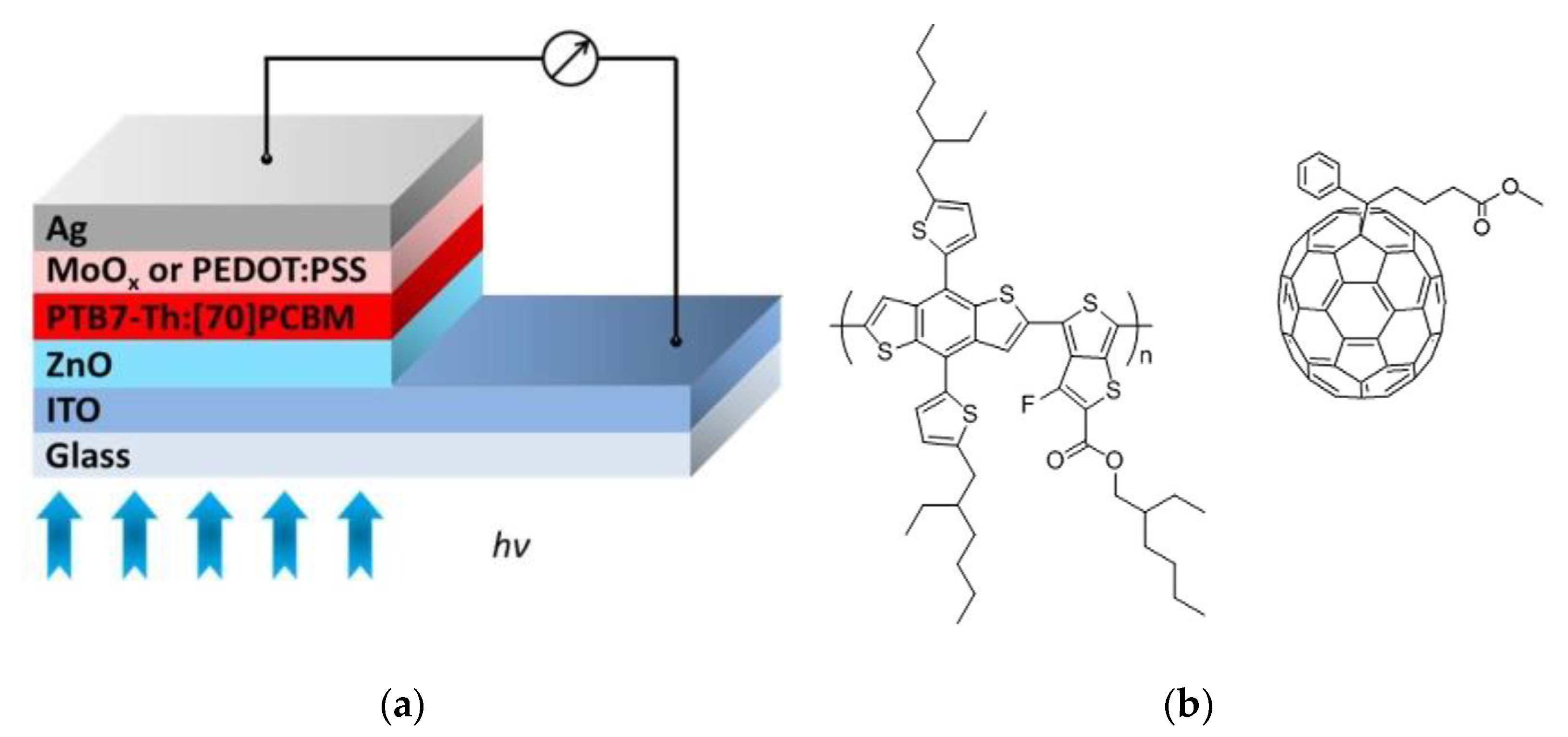
In order to test the performance of the thermally evaporated MoOx layer as an HTL in inverted PSCs, we have realized devices with the following architecture: glass/ITO/ZnO/PTB7-Th:[70]PCBM/HTL/Ag, where the HTL is MoOx or PEDOT:PSS. The investigated structure is depicted in Figure 2 together with the chemical structure of the materials used to prepare the photoactive layer. PTB7-Th is a low-band gap polymer recently used as a donor material in PSCs, showing PCE larger than 10% using an inverted device structure [39]. This material has several advantages but also some important drawbacks. On the negative side, solar cells based on PTB7-like and fullerene are generally known to be thermally unstable due to deterioration of the blend morphology at high temperatures [40,41]. On the other hand, it has been demonstrated that this type of polymer can be considered a promising material thanks to the possibility of processing it under ambient conditions using roll-to-roll or compatible production methods [42].
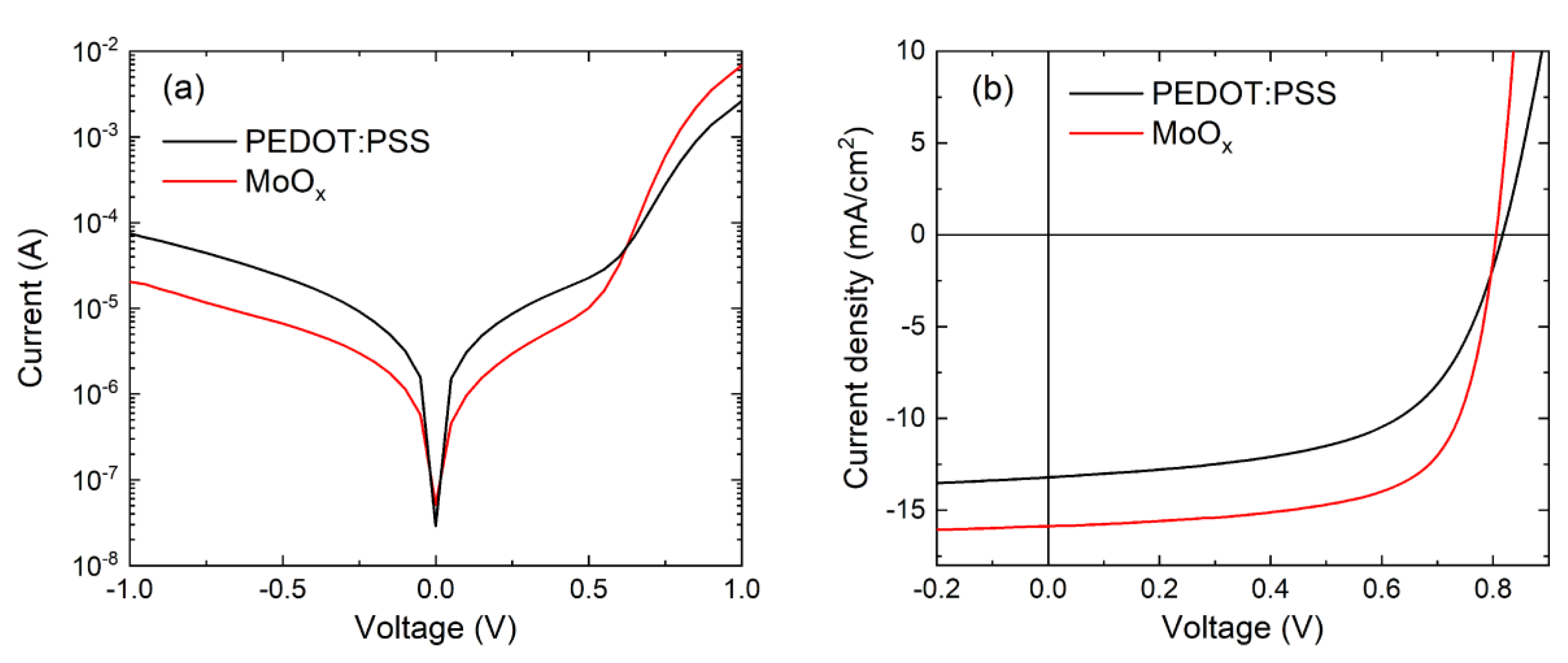
The current–voltage characteristics (in dark and under illuminated conditions) of the two investigated devices are reported in Figure 3. Both the dark I-V curves show a rectification behavior at ±1 V, and the reverse current is between 10−5 and 10−4 A. When comparing the two types of cells, the MoOx-based device shows a lower series resistance and a higher shunt resistance.
The values of PCE, open circuit voltage (VOC), short circuit current density (JSC), and fill factor (FF) extracted from the illuminated J-V curve (Figure 3b) are summarized in Table 1. A minimum of 5 cells was realized for each device configuration, and good reproducibility was found (within 2%) for all the extracted J-V light parameters. The best performance is obtained with the device realized by using MoOx as an HTL, which reaches a PCE of 8.67% compared to 6.23% of the PEDOT:PSS-based cell. The higher PCE value is mainly due to the improved FF (67.8% versus 58.3%) and to the higher Jsc (15.9 versus 13.1 mA/cm2).
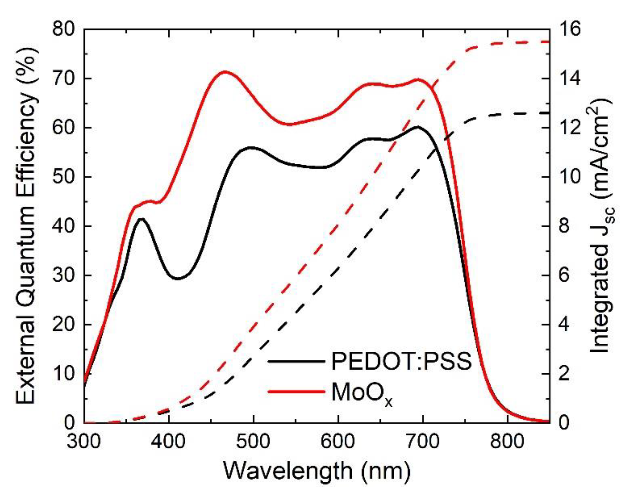
The EQE of PSCs realized with different HTLs (PEDOT:PSS or MoOx) is reported in Figure 4. Both the devices show a broad response range from 300 to 850 nm (in agreement with the EQE reported in the literature for cells based on the same photoactive layer [39]), with values above 50% (PEDOT:PSS-based device) and 60% (MoOx-based device) in the range 500–700 nm. The response of the MoOx-based device is larger compared to the PEDOT:PSS one, confirming the improved current output observed from the corresponding illuminated J-V curves. The higher current of the device with MoOx as HTL is mainly due to the higher light absorption achieved by the photoactive layer in this configuration, thanks to the lower extincion coefficient of MoOx versus PEDOT:PSS for wavelengths above 400 nm, as found through spectroscopic ellipsometry (Figure 1). This is explained by the fact that when light enters the solar cells through the front contact (ITO), it is partially absorbed by the active layer, while a fraction reaches the Ag back reflecting contact. Thanks to the reduced parasitic absorption losses in the MoOx layer, more light is reflected backwards into the photoactive layer, which thus has a better “second chance” to absorb it and produce a higher current output. In addition, also an improved charge collection likely contributes to enhance the EQE curve of the MoOx-based device overall, which is in agreement with the higher FF.

3.3. Silicon Heterojunction Solar Cells

For the application of MoOx at the back side of SHJ solar cells, we have considered the three proof-of-concept planar structures in Figure 5, which make use of a single-layer rear-reflector (the Ag back electrode) and the same front layer stack featuring a highly transparent n-type layer [37,43]. The structure in panel (a), which uses a conventional p-type doped Si-based layer (amorphous silicon in the present case), is the reference solar cell. In (b), we have considered the replacement of the conventional hole collector with MoOx, while keeping the same wafer type. We have additionally tested the (c) structure, which is the same as (b) but based on the n-type wafer. Although MoOx serves as a hole collector in both the (b) and (c) structures, there are differences in the hole transport mechanism toward the rear electrode, since holes are majority (minority) carriers in p-type (n-type) wafers.
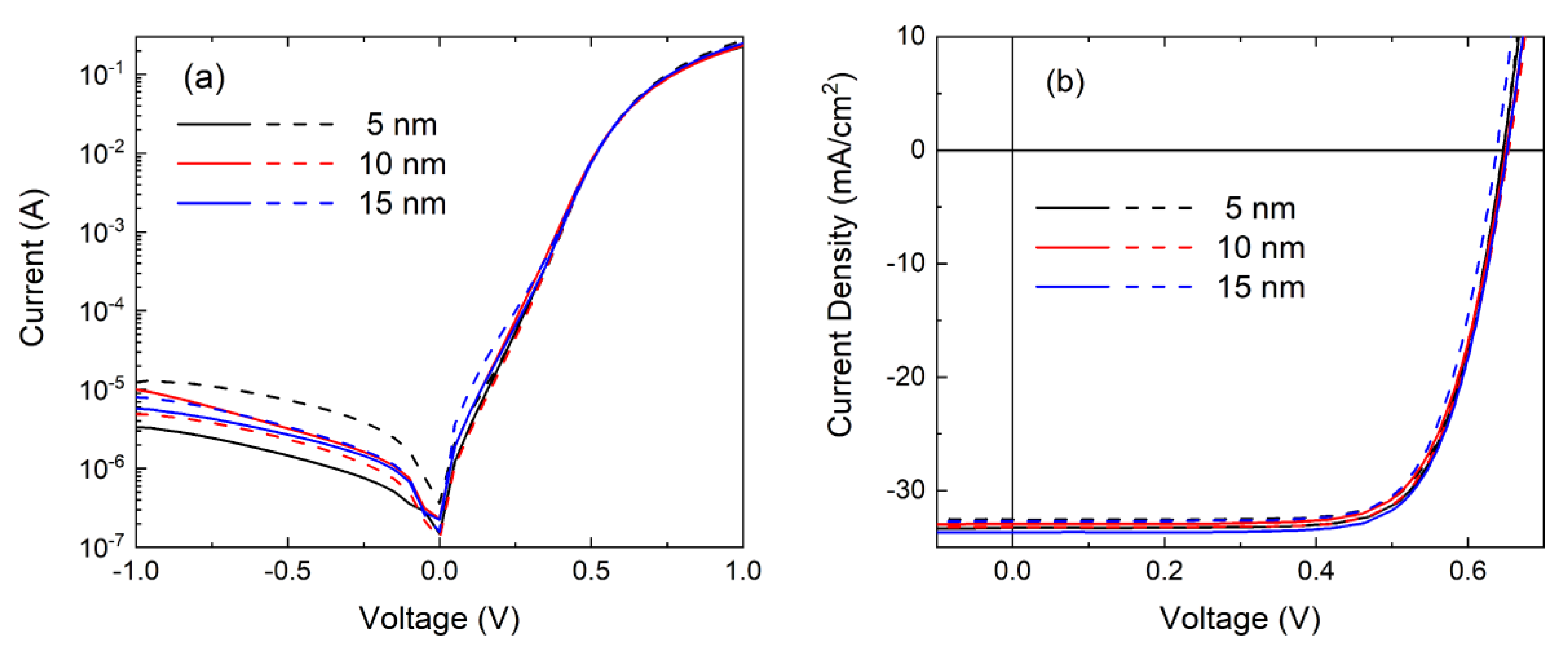
Ultrathin MoOx is required in the devices to avoid series resistance losses due to the poor conductivity of the material (fully stoichiometric MoO3 is insulating). To establish the appropriate values, we have conducted a preliminary experiment on structure (b) fabricating solar cells with variable MoOx thickness (5, 10, and 15 nm) and nominally identical intrinsic and n-type layers. Dark and illuminated current–voltage curves are shown in Figure 6 for two representative cells for each MoOx thickness value, which are selected to give direct evidence of the variability within each set of cells. Functioning solar cells have been obtained in all the cases. All the dark I-V curves show low reverse current (<10−5 A) and proper rectification behavior (ratio of forward over reverse current ≥ 104 at ±1 V), giving indication of a good passivation level and low shunt effects. No effects on the series resistance are visible when changing the MoOx thickness. The only relevant difference is the bigger variability in the leakage current among the cells with the thinnest MoOx layer. In addition, from the illuminated J-V curves, no major variation on the thickness is found for all the photovoltaic parameters (VOC approximately 650 mV, FF approximately 73%, JSC approximately 33 mA/cm2), thus leaving relaxed margins for the application.
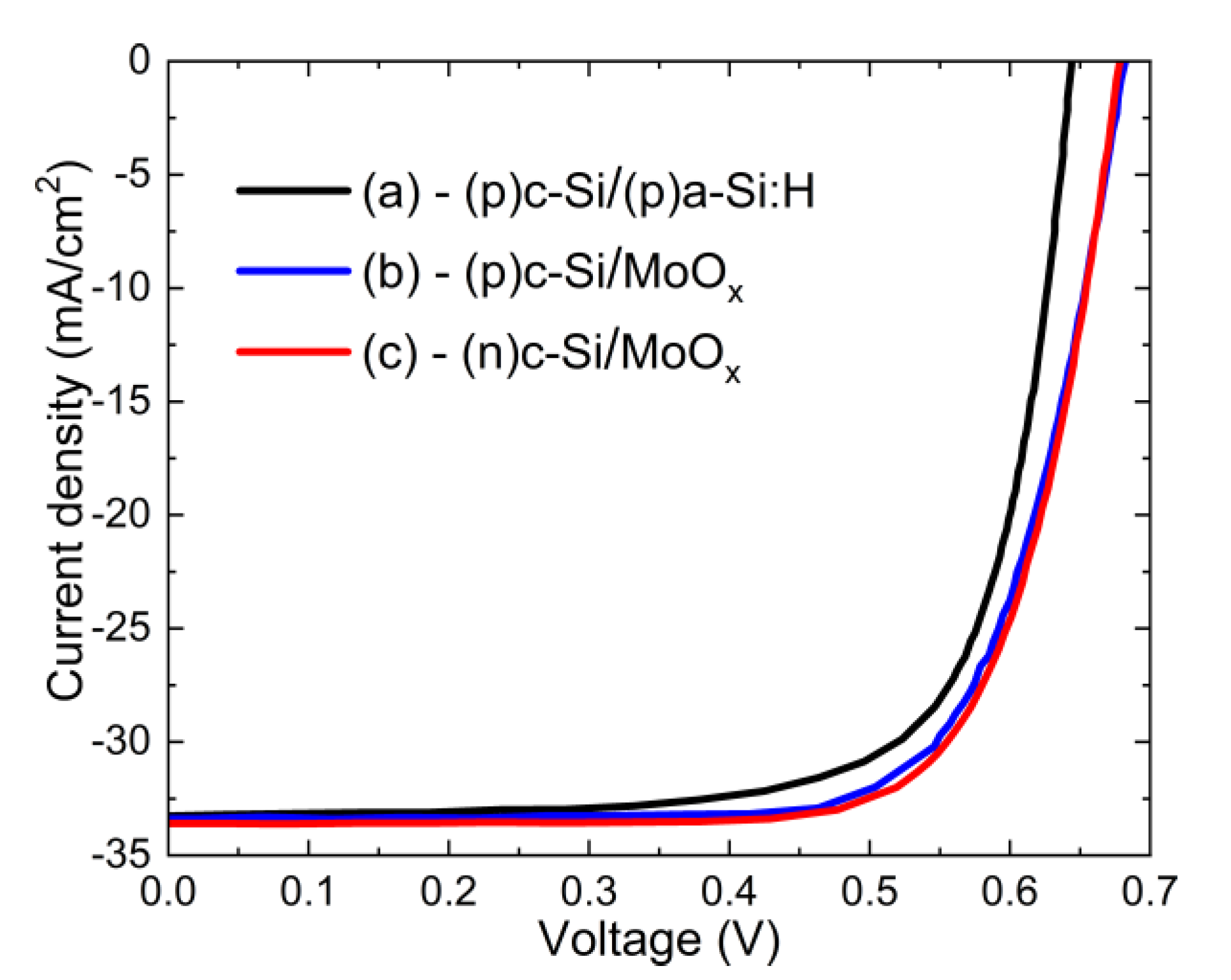
Based on the preliminary test, the intermediate value of 10 nm has been selected for the MoOx layer thickness to be applied for the comparison of the structures in Figure 5. While in the front side application MoOx can supply a relevant optical gain thanks to the inferior parasitic absorption of light in the ultraviolet and visible region of the solar spectrum (Figure 1), here, considering that only the near infrared light reaches the bottom of the Si wafer, MoOx and (p)a-Si:H are roughly equivalent, being both transparent in the long wavelength range. Therefore, no optical gain is here pursued, but there are margins for electrical improvement together with the technological simplification related to the use of an evaporated dopant-free layer. The J-V curves under illumination and the corresponding photovoltaic parameters for the best cells with the three designs, with nominally identical intrinsic and n-type layers, are reported in Figure 7 and Table 2, respectively. Compared to the reference cell, a considerable increase of VOC (38 mV) is obtained when moving from (p)a-Si:H to the MoOx collector. At the same time, FF and JSC remain comparable, leading to an overall increase of the conversion efficiency of approximately 1% absolute. Remarkably, the solar cells based on the n-type wafer, where the MoOx layer functions as a non-conventional emitter placed on the back side (structure (c)), show very similar characteristics and thus similar improvement against the selected reference cell. In this case, there is a margin for significant additional gain with optimization of the front stack, which here was left unchanged for comparison.
These results demonstrate the effectiveness of the MoOx hole collector at the rear of SHJ solar cells, irrespective of the wafer doping type. The significant VOC increase against the reference cell is likely the effect of the improved surface passivation achieved for the Si wafer in the presence of the full (i)a-Si:H plus hole-collector stack when MoOx replaces (p)a-Si:H. It is known that when (p)a-Si:H is deposited over the ultrathin (i)a-Si:H passivation layer, the injection-level dependent lifetime drops [38,44]. However, the suggested more favorable condition achieved with MoOx would be challenging to demonstrate with lifetime measurements carried out on unfinished cell precursors (i.e., with unprotected MoOx), due to the high sensitivity of MoOx to air exposure.

4. Conclusions

We have reported on the application of ultrathin evaporated MoOx as a hole collector at the back side of solar cells of two very different photovoltaic technologies. In case of polymer solar cells, MoOx has been tested against a standard HTL made of PEDOT:PSS in devices with inverted architecture employing the PTB7-Th:[70]PCBM blend as a photoactive layer. The MoOx-based PSCs have shown superior performance in terms of the current output and fill factor compared to the reference with PEDOT:PSS. The superior transparency of the MoOx film allows an enhanced back reflected light inside the blend film, producing a higher photogeneration, as found from the illuminated J-V and EQE curves. The higher FF of the MoOx-based device also suggests a better charge collection efficiency.
As for the SHJ technology, we have reported on the use of MoOx as a rear dopant-free hole collector. We have demonstrated the efficacy of the approach when using both p-type and n-type Si wafers and evidenced a potential efficiency gain. In the present comparison over planar test structures with an Ag back reflecting electrode, the increase has been approximately 1% absolute against a standard p-type amorphous silicon hole collector. The gain is linked to the increased VOC, which is likely due to the reduced recombination at the Si wafer surface when passivated by the (i)a-Si:H/MoOx stack in place of (i)a-Si:H/(p)a-Si:H. We have elsewhere shown that the detrimental effects of the highly defective (p)a-Si:H collection layer can be partly overcome by using p-type doped nanocrystalline Si layers with superior electrical properties [38], but the replacement of doped Si-based layers with MoOx offers the advantage of a low-temperature low-cost fabrication technique and no need of toxic doping gases in the fabrication process. In addition, less variability is expected in the solar cell results by avoiding the delicate tuning of the deposition parameters of the doped amorphous and nanocrystalline Si layers required for obtaining the optimal optoelectronic properties of the layers.

Author Contributions

Conceptualization, P.M. and L.V.M.; methodology, P.M., L.V.M., and P.D.V.; investigation, E.B., I.U., P.M., L.V.M., M.D.N., L.L., C.S. and R.R.; writing—original draft preparation, review and editing, E.B., P.M. and L.V.M.; project administration, P.D.V. All authors have read and agreed to the published version of the manuscript.

Funding

This work was supported by the Italian Ministry of Economic Development in the framework of the Operating Agreement with ENEA for Research on the Electric System and by the Italian Ministry of Education, Universities and Research through the E-Design project (MIUR-PON 2017).

Conflicts of Interest

The authors declare no conflict of interest.

References

  1. Bullock, J.; Cuevas, A.; Allen, T.; Battaglia, C. Molybdenum oxide MoOx: A versatile hole contact for silicon solar cells. Appl. Phys. Lett. 2014, 105, 232109. [Google Scholar] [CrossRef]
  2. Bivour, M.; Temmler, J.; Steinkemper, H.; Hermle, M. Molybdenum and tungsten oxide: High work function wide band gap contact materials for hole selective contacts of silicon solar cells. Sol. Energy Mater. Sol. Cell 2015, 142, 34–41. [Google Scholar] [CrossRef]
  3. Geissbühler, J.; Werner, J.; Martin de Nicolas, S.; Barraud, L.; Hessler-Wyser, A.; Despeisse, M.; Nicolay, S.; Tomasi, A.; Niesen, B.; De Wolf, S.; et al. 22.5% Efficient Silicon Heterojunction Solar Cell with Molybdenum Oxide Hole Collector. Appl. Phys. Lett. 2015, 107, 081601. [Google Scholar] [CrossRef] [Green Version]
  4. Bullock, J.; Hettick, M.; Geissbühler, J.; Ong, A.J.; Allen, T.; Sutter-Fella, C.M.; Chen, T.; Ota, H.; Schaler, E.W.; De Wolf, S.; et al. Efficient silicon solar cells with dopant-free asymmetric heterocontacts. Nat. Energy 2016, 2, 15031. [Google Scholar] [CrossRef]
  5. Essig, S.; Dreon, J.; Rucavado, E.; Mews, M.; Koida, T.; Boccard, M.; Werner, J.; Geissbühler, J.; Löper, P.; Morales-Masis, M.; et al. Toward Annealing-Stable Molybdenum-Oxide-Based Hole-Selective Contacts for Silicon Photovoltaics. Solar RRL 2018, 2, 1700227. [Google Scholar] [CrossRef]
  6. Avigad, E.; Etgar, L. Studying the Effect of MoO3 in Hole-Conductor-Free Perovskite Solar Cells. ACS Energy Lett. 2018, 3, 2240–2245. [Google Scholar] [CrossRef]
  7. Dréon, J.; Jeangros, Q.; Cattin, Y.; Haschke, J.; Antognini, L.; Ballif, C.; Boccard, M. 23.5%-efficient silicon heterojunction silicon solar cell using molybdenum oxide as hole-selective contact. Nano Energy 2020, 70, 104495. [Google Scholar] [CrossRef]
  8. Wu, W.; Lin, W.; Zhong, S.; Paviet-Salomon, B.; Despeisse, M.; Jeangros, Q.; Liang, Z.; Boccard, M.; Shen, H.; Ballif, C. Dopant-Free Back-Contacted Silicon Solar Cells with an Efficiency of 22.1%. Phys. Status Solidi RRL 2020, 14, 1900688. [Google Scholar] [CrossRef]
  9. Yoosuf Ameen, M.; Shamjid, P.; Abhijith, T.; Radhakrishnan, T.; Reddy, V.S. Stability enhancement of P3HT:PCBM polymer solar cells using thermally evaporated MoO3 anode buffer layer. Physica B 2018, 530, 201–207. [Google Scholar] [CrossRef]
  10. Chong, L.; Wenzhe, L.; Jianhui, C.; Jiandong, F.; Yaohua, M.; Schropp, R.E.I. Ultra-thin MoOx as cathode buffer layer for the improvement of all-inorganic CsPbIBr2 perovskite solar cells. Nano Energy 2017, 41, 75–83. [Google Scholar]
  11. Miyasaka, T.; Kulkarni, A.; Kim, G.M.; Öz, S.; Jena, A.K. Perovskite Solar Cells: Can We Go Organic-Free, Lead-Free, and Dopant-Free? Adv. Energy Mater. 2020, 10, 1902500. [Google Scholar] [CrossRef]
  12. Pant, N.; Kulkarni, A.; Yanagida, M.; Shirai, Y.; Miyasaka, T.; Miyano, K. Investigating the Growth of CH3NH3PbI3 Thin Films on RF-Sputtered NiOx for Inverted Planar Perovskite Solar Cells: Effect of CH3NH3+ Halide Additives versus CH3NH3+ Halide Vapor Annealing. Adv. Mater. Interfaces 2020, 7, 1901748. [Google Scholar] [CrossRef]
  13. Meyer, J.; Hamwi, S.; Kröger, M.; Kowalsky, W.; Riedl, T.; Kahn, A. Transition Metal Oxides for Organic Electronics: Energetics, Device Physics and Applications. Adv. Mater. 2012, 24, 5408–5427. [Google Scholar] [CrossRef] [PubMed]
  14. Irfan, D.H.; Gao, Y.; Small, C.; Kim, D.-Y.; Subbiah, Y.; So, F. Energy level evolution of air and oxygen exposed molybdenum trioxide films. Appl. Phys. Lett. 2010, 96, 243307. [Google Scholar] [CrossRef]
  15. Werner, J.; Geissbühler, J.; Dabirian, A.; Nicolay, S.; Morales-Masis, M.; De Wolf, S.; Niesen, B.; Ballif, C. Parasitic Absorption Reduction in Metal Oxide-Based Transparent Electrodes: Application in Perovskite Solar Cells. ACS Appl. Mater. Interfaces 2016, 8, 17260–17267. [Google Scholar] [CrossRef]
  16. Jørgensen, M.; Carlé, J.E.; Søndergaard, R.R.; Lauritzen, M.; Dagnæs-Hansen, N.A.; Byskov, S.L.; Andersen, T.R.; Larsen-Olsen, T.T.; Böttiger, A.P.L.; Andreasen, B.; et al. The state of organic solar cells—A meta analysis. Sol. Energy Mater. Sol. Cells 2013, 119, 84–93. [Google Scholar] [CrossRef]
  17. Krebs, F.C.; Fyenbo, J.; Jørgensen, M. Product integration of compact roll-to-roll processed polymer solar cell modules: Methods and manufacture using flexographic printing, slot-die coating and rotary screen printing. J. Mater. Chem. 2010, 20, 8994–9001. [Google Scholar] [CrossRef]
  18. Krebs, F.C. Fabrication and processing of polymer solar cells: A review of printing and coating techniques. Sol. Energy Mater. Sol. Cells 2009, 93, 394–412. [Google Scholar] [CrossRef]
  19. Krebs, F.C.; Tromholt, T.; Jørgensen, M. Upscaling of polymer solar cell fabrication using full roll to-roll processing. Nanoscale 2010, 2, 873–886. [Google Scholar] [CrossRef]
  20. Dam, H.F.; Andersen, T.R.; Madsen, M.V.; Mortensen, T.K.; Pedersen, M.F.; Nielsen, U.; Krebs, F.C. Roll and roll-to-roll process scaling through development of a compact flexo unit for printing of back electrodes. Sol. Energy Mater. Sol. Cells 2015, 140, 187–192. [Google Scholar] [CrossRef]
  21. Liu, Q.; Jiang, Y.; Jin, K.; Qin, J.; Xu, J.; Li, W.; Xiong, J.; Liu, J.; Xiao, Z.; Sun, K.; et al. 18% Efficiency organic solar cells. Sci. Bull. 2020, 65, 272–275. [Google Scholar] [CrossRef] [Green Version]
  22. Jørgensen, M.; Norrman, K.; Gevorgyan, S.A.; Tromholt, T.; Andreasen, B.; Krebs, F.C. Stability of polymer solar cells. Adv. Mater. 2012, 24, 580–612. [Google Scholar] [CrossRef] [PubMed]
  23. He, Z.; Zhong, C.; Su, S.; Xu, M.; Wu, H.; Cao, Y. Enhanced power-conversion efficiency in polymer solar cells using an inverted device structure. Nat. Photonics 2012, 6, 591–595. [Google Scholar] [CrossRef]
  24. Hau, S.K.; Yip, H.L.; Jen, A.K.Y. A Review on the Development of the Inverted Polymer Solar Cell Architecture. Polym. Rev. 2010, 50, 474–510. [Google Scholar] [CrossRef]
  25. Xu, M.F.; Cui, L.S.; Zhu, X.Z.; Gao, C.H.; Shi, X.B.; Jin, Z.M.; Wang, Z.K.; Liao, L.S. Aqueous solution-processed MoO3 as an effective interfacial layer in polymer/fullerene based organic solar cells. Org. Electron. 2013, 14, 657–664. [Google Scholar] [CrossRef]
  26. Morvillo, P.; Ricciardi, R.; Nenna, G.; Bobeico, E.; Diana, R.; Minarini, C. Elucidating the origin of the improved current output in inverted polymer solar cells. Sol. Energy Mater. Sol. Cells 2016, 152, 51–58. [Google Scholar] [CrossRef]
  27. Morvillo, P.; Diana, R.; Nenna, G.; Bobeico, E.; Ricciardi, R.; Minarini, C. High performance inverted polymer solar cells with solution processed metal oxides as electron transport layers: A comparative study. Thin Solid Films 2016, 617, 126–132. [Google Scholar] [CrossRef]
  28. Yoshikawa, K.; Kawasaki, H.; Yoshida, W.; Irie, T.; Konishi, K.; Nakano, K.; Uto, T.; Adachi, D.; Kanematsu, M.; Uzu, H.; et al. Silicon heterojunction solar cell with interdigitated back contacts for a photoconversion efficiency over 26%. Nat. Energy 2017, 2, 17032. [Google Scholar]
  29. Adachi, D.; Hernandez, J.L.; Yamamoto, K. Impact of carrier recombination on fill factor for large area heterojunction crystalline Si solar cell with 25.1% efficiency. Appl. Phys. Lett. 2015, 107, 233506. [Google Scholar] [CrossRef]
  30. Bivour, M.; Schröer, S.; Hermle, M.; Glunz, S.W. Silicon heterojunction rear emitter solar cells: Less restrictions on the optoelectrical properties of front side TCOs. Sol. Energy Mater. Sol. Cell. 2014, 122, 120–129. [Google Scholar] [CrossRef]
  31. Mazzarella, L.; Morales-Vilches, A.B.; Korte, L.; Schlatmann, R.; Stannowski, B. Ultra-thin nanocrystalline n-type silicon oxide front contact layers for rear emitter silicon heterojunction solar cells. Solar Energy Mater. Solar Cells 2018, 179, 386–391. [Google Scholar] [CrossRef]
  32. Niemelä, J.P.; Macco, B.; Barraud, L.; Descoeudres, A.; Badel, N.; Despeisse, M.; Christmann, G.; Nicolay, S.; Ballif, C.; Kessels, W.M.M.; et al. Rear-emitter silicon heterojunction solar cells with atomic layer deposited ZnO:Al serving as an alternative transparent conducting oxide to In2O3:Sn. Sol. Energy Mater. Sol. Cell. 2019, 200, 109953. [Google Scholar] [CrossRef]
  33. Baikie, I.D.; Estrup, P.J. Low cost PC based scanning Kelvin probe. Rev. Sci. Instrum. 1998, 69, 3902–3907. [Google Scholar] [CrossRef]
  34. Lancellotti, L.; Bobeico, E.; Della Noce, M.; Delli Veneri, P.; Matacena, I. Work Function Determination of Transparent Contact for a:Si/c-Si Heterojunction Solar Cells. In Proceedings of the 2018 IEEE International Conference on Environment and Electrical Engineering and 2018 IEEE Industrial and Commercial Power Systems Europe, EEEIC/I and CPS Europe2018, Palermo, Italy, 12–15 June 2018; pp. 1–5. [Google Scholar]
  35. Morvillo, P.; Diana, R.; Ricciardi, R.; Bobeico, E.; Minarini, C. High efficiency inverted polymer solar cells with solution-processed ZnO buffer layer. J. Sol-Gel Sci. Technol. 2015, 73, 550–556. [Google Scholar] [CrossRef]
  36. Long, G.; Wu, B.; Yang, X.; Kan, B.; Zhou, Y.; Chen, L.; Wan, X.; Zhang, H.; Sum, T.C.; Chen, Y. Enhancement of Performance and Mechanism Studies of All-Solution Processed Small-Molecule based Solar Cells with an Inverted Structure. ACS Appl. Mater. Interfaces 2015, 7, 21245–21253. [Google Scholar] [CrossRef]
  37. Mercaldo, L.V.; Usatii, I.; Delli Veneri, P. Advances in thin-film Si solar cells by means of SiOx alloys. Energies 2016, 9, 218. [Google Scholar] [CrossRef] [Green Version]
  38. Mercaldo, L.V.; Bobeico, E.; Usatii, I.; Della Noce, M.; Lancellotti, L.; Serenelli, L.; Izzi, M.; Tucci, M.; Veneri, P.D. Potentials of mixed-phase doped layers in p-type Si heterojunction solar cells with ZnO:Al. Sol. Energy Mater. Sol. Cells 2017, 169, 113–121. [Google Scholar] [CrossRef]
  39. Wan, Q.; Guo, X.; Wang, Z.; Li, W.; Guo, B.; Ma, W.; Zhang, M.; Li, Y. 10.8% Efficiency Polymer Solar Cells Based on PTB7-Th and PC71BM via Binary Solvent Additives Treatment. Adv. Funct. Mater. 2016, 26, 6635–6640. [Google Scholar] [CrossRef]
  40. Wong, H.C.; Li, Z.; Tan, C.H.; Zhong, H.; Huang, Z.; Bronstein, H.; McCulloch, I.; Cabral, J.T.; Durrant, J.R. Morphological Stability and Performance of Polymer–Fullerene Solar Cells under Thermal Stress: The Impact of Photoinduced PC60BM Oligomerization. ACS Nano 2014, 2, 1297–1308. [Google Scholar] [CrossRef]
  41. Wantz, G.; Derue, L.; Dautel, O.; Rivaton, A.; Hudhomme, P.; Dagron-Lartigau, C. Stabilizing polymer-based bulk heterojunction solar cells via crosslinking. Polym. Int. 2014, 63, 1346–1361. [Google Scholar] [CrossRef]
  42. Li, N.; Brabec, C.J. Air-processed polymer tandem solar cells with power conversion efficiency exceeding 10%. Energy Environ. Sci. 2015, 2, 2902–2909. [Google Scholar] [CrossRef] [Green Version]
  43. Izzi, M.; Tucci, M.; Serenelli, L.; Mangiapane, P.; Della Noce, M.; Usatii, I.; Esposito, E.; Mercaldo, L.V.; Delli Veneri, P. Doped SiOx emitter layer in amorphous/crystalline silicon heterojunction solar cell. Appl. Phys. A 2014, 115, 705–712. [Google Scholar] [CrossRef]
  44. De Wolf, S.; Kondo, M. Nature of doped a-Si:H/c-Si interface recombination. J. Appl. Phys. 2009, 105, 103707. [Google Scholar] [CrossRef] [Green Version]
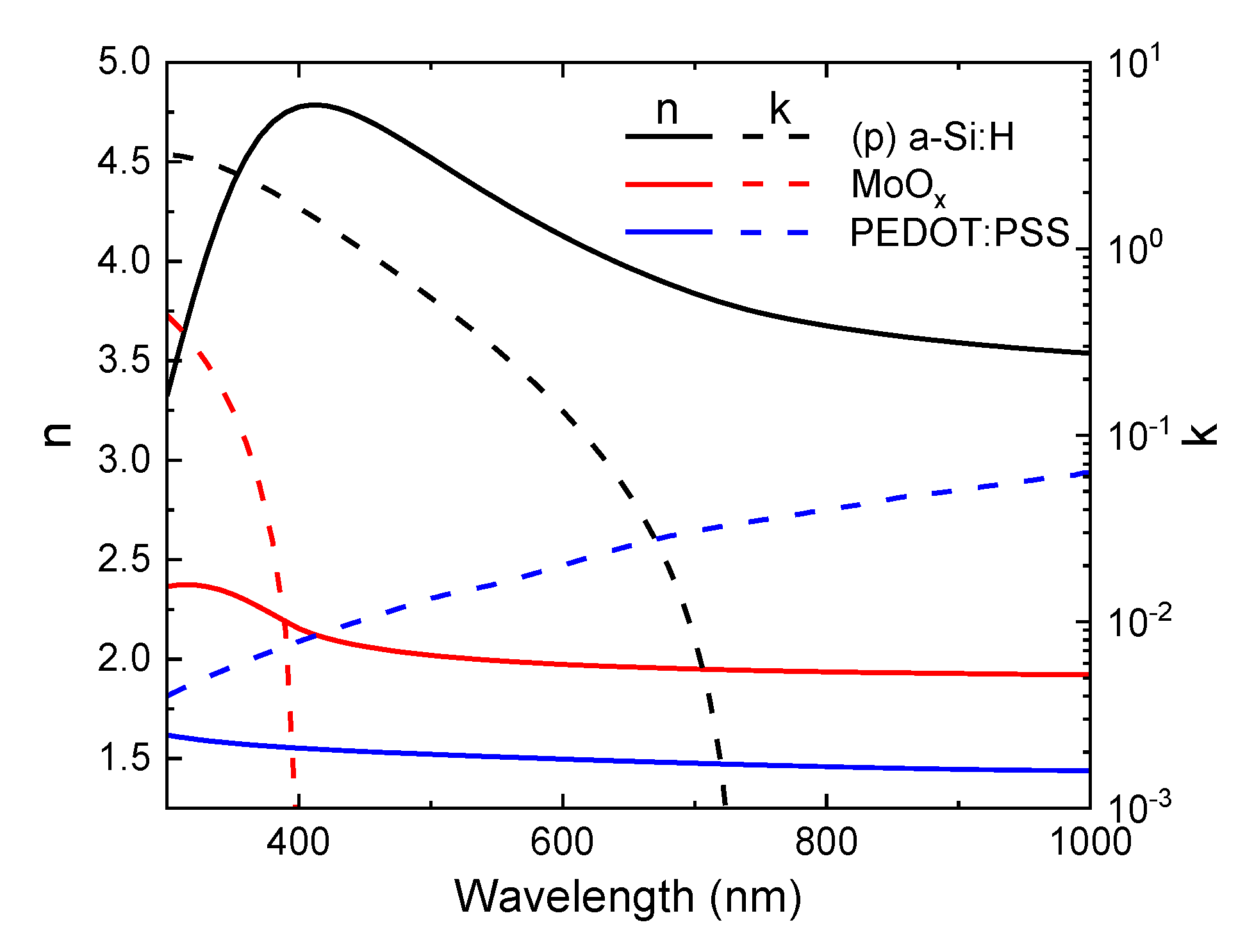
Figure 1. Refractive index (n) and extinction coefficient (k) spectra of the films applied as hole collectors in the present work, as evaluated through spectroscopic ellipsometry.
Coatings 10 00763 g001
Figure 2. (a) Device architecture of the investigated inverted polymer solar cells; (b) Chemical structures of PTB7-Th and [70]PCBM (major isomer).
Coatings 10 00763 g002
Figure 3. Current–voltage characteristics in the dark (a) and under AM1.5 illumination (b) of inverted polymer solar cells (PSCs) with different hole transport layers (HTLs) (poly(3,4-ethylenedioxythiophene):poly(styrenesulfonate) (PEDOT:PSS) or MoOx) based on the structure illustrated in Figure 2.
Coatings 10 00763 g003
Figure 4. External quantum efficiency (solid lines, left axis) of inverted PSCs with different HTLs (PEDOT:PSS or MoOx) based on the structure illustrated in Figure 2. The integrated JSC calculated from the external quantum efficiency (EQE) spectra is also reported (dashed lines, right axis).
Coatings 10 00763 g004
Figure 5. Schematic drawings (not to scale) of the silicon heterojunction solar cell structures investigated in this work, all with hole collectors at the back side (opposite to illumination): (a) p-type Si wafer with front emitter and conventional hole collector; (b) p-type Si wafer with front emitter and novel hole collector; (c) n-type Si wafer with novel hole collector functioning also as a rear emitter.
Coatings 10 00763 g005
Figure 6. Current–voltage characteristics in the dark (a) and under AM1.5 illumination (b) of p-type based silicon heterojunction (SHJ) solar cells with an MoOx hole collector (structure (b) in Figure 5) for three MoOx thickness values.
Coatings 10 00763 g006
Figure 7. J-V characteristics under illumination of SHJ solar cells with different hole collectors ((p)a-Si:H or MoOx) based on p-type and n-type Si wafers designed as illustrated in Figure 5.
Coatings 10 00763 g007
Table 1. Performance parameters relative to the J-V curves shown in Figure 3. FF: fill factor.
HTLVOC (mV)JSC (mA/cm2)FF (%)η (%)
PEDOT:PSS81713.158.36.23
MoOx80515.967.88.67
Table 2. Performance parameters relative to the J-V curves shown in Figure 7.
Cell StructureSi WaferHole
Collector
VOC
(mV)
JSC
(mA/cm2)
FF
(%)
η
(%)
a(p)c-Si(p)a-Si:H64433.273.015.6
b(p)c-SiMoOx68233.472.516.5
c(n)c-SiMoOx67833.673.516.7