Article

Surface Treatments Solutions to Green Tribology

Fundación Tekniker, c/Iñaki Goenaga, 5, 20600 Eibar, Spain
*
Author to whom correspondence should be addressed.
Coatings 2020, 10(7), 634; https://doi.org/10.3390/coatings10070634
Submission received: 21 December 2019 / Revised: 10 June 2020 / Accepted: 16 June 2020 / Published: 30 June 2020
(This article belongs to the Special Issue Recent Advances in Green Tribology)

Abstract

:
The objective of this paper is to highlight the need to combine lifecycle environmental assessment with durability evaluation (tribology and engine tests) to evaluate the potential of surface technologies to contribute to the green deal, in order to make Europe the first climate-neutral continent. Tribology is a scientific discipline that allows one to understand the system reaction to friction and wear. Tribological testing machines are prepared to measure friction at the laboratory level to minimize the wear and heat dissipation of two bodies in relative movement, thus improving the energy efficiency and minimizing CO2 emissions. In this paper, different surface technologies, such as high-velocity oxyfuel (HVOF), physical vapor deposition (PVD), and clean Cr electrolytic processes, are analyzed as promising surface technology solutions from both performance and environmental impact perspectives to replace harmful Cr(VI) coatings. The tribology simulates the working conditions of the real system at the laboratory level, reproducing the failure mechanism and facilitating the laboratory screening of the energy efficiency and durability of materials solutions for certain tribological systems—in this case, engine components. The tribological test results give information about the behavior of materials, while the engine tests gives information about the behavior of components. In this paper, the environmental impact of the production process of the coatings is also analyzed. Two hard chrome processes are compared, demonstrating that by controlling the production process it is possible to significantly reduce the environmental impact of the chrome-plated process, minimizing the environmental impact to that of PVD coatings. The environmental impact of the tested HVOF process is lower than traditional Cr(VI)-plated coatings but higher than PVD coatings. Combining the information from the lifecycle assessment (LCA) and tribological studies, it is possible to assess both the performance and the environmental impact of the surface treatments. This methodology is a tool to that can be used minimize CO2 emissions at the design phase to improve the energy efficiency of products and processes.

1. Introduction

European Union regulations regarding the maximum amount of Cr(VI) content allowable in automotive vehicles are in place. Together with environmental, health and safety regulations, Cr(VI) regulations are driving research initiatives to find substitutes for Cr(VI)-based coatings. For hard chrome, the aesthetic appearance and good performance of coatings made from this material, in terms of wear and corrosion resistance for different automotive components have made many industries reluctant to introduce new alternatives. In the current EU legislation, the maximum allowable mass of hexavalent chromium is 2 g per vehicle [1]. Although the hard-chrome-plated components are not part of this legislation (as hard-chrome is Cr(0), in keeping with environmental policy, the exposure of workers to and the environmental load of Cr(VI) during the coating process of hard-chrome on components need to be considered [2,3]. In order to evaluate the environmental loads, a life cycle environmental impact assessment (LCA) was devised [4]. The ReCiPe 2016 methodology was used to quantify the ecological impact of the different coating manufacturing processes. [5].
Friction reduction, particularly in mobility is the core aspect for improved energy efficiency. It reduces CO2 emissions and decreases the dependency of energy imports. The proportion of friction losses of the primary energy consumption is 23%, with it being possible to reduce primary energy consumption controlling friction losses by 8.6%. Results provided by the research cluster for low friction powertrains showed that engine friction losses offer a reduction potential of 30%. This would translate into a fuel consumption reduction of 0.94l/100 km or 12.1% along with additional reduction potentials for the transmission, wheel bearings and auxiliary units of the powertrain. If the calculated 12.1% fuel consumption reduction was applied to the fuel quantity sold with the fully exploited friction reduction potential, the fuel quantity consumed in Germany could be reduced by 2.2 million tons of gasoline, amounting to CO2 emissions reductions of 6.92 million tons. The diesel consumption could be reduced by 4.68 million tons, translating into approximate CO2 emission reductions of 14.95 million tons. Overall, almost 22 million tons of CO2 or 6.4% of the CO2 reduction could be saved by the German government by 2030 via friction reduction without affecting the utility value [6].
Advanced surface treatments materials such as coatings (e.g., high-velocity oxyfuel (HVOF), physical vapor deposition (PVD)) or surface treatments (e.g., nitriding) used currently, might carry out multiple functions in devices where two bodies are in relative movement (e.g., support load, lower friction, self-healing capability, energy absorption), enabling the design of products, machinery, vehicles and services for our daily life. In certain applications, such as for cutting tools or aesthetic small components with mainly external surfaces, PVD coatings cover most of the market [6,7,8]. HVOF coatings are replacing Cr(VI) in the aeronautic market and some industrial applications for big components with external surfaces [9]. One of the limitations for their widespread use, is the difficulty to reproduce at laboratory level the durability and reliability of new coating solutions in real applications [10]. The second limitation is the difficulty to apply the coating in internal diameters [11].
One of the ways where materials research can contribute to the green deal [12], is the possibility to tailor the tribological behaviour of the surface treatments in the design phase for products and processes. Tribology is a great tool to gain a better understanding of the system reactions in tribological contact. It helps to screen surface treatments by ranking materials based on their durability, friction and contact temperature minimization. This has been highlighted by the authors in a previous review paper [13], the main tribological achievements carried out in TEKNIKER over the past 37 years. It covers the description of commercial and newly developed tribological test benches and tribological solutions for a wide variety of applications. The study refers to different tribological characterization tools for material selection (e.g., composition, surface treatments, lubricants). There is an emphasis in the failure mechanisms (pitting, scuffing, abrasion, adhesion, thermal fatigue, tribocorrosion, etc.) and friction simulation of a wide range of materials (seals, textiles, steels, cast iron, light alloys, ceramic, composites), tribological systems (mechanical components, biomaterials, tribolubrication), and environments (vacuum, ultrahigh vacuum, low or high temperature, and corrosive). A huge range of new testing equipments and protocols have been developed to simulate the mentioned failure mechanisms and working environments. Tribology will help to implement materials solutions into energy and resource efficient products and processes with the aim to reduce the carbon footprint. In this paper, a step forward has been achieved by combining the data from tribological and engine tests with a lifecycle environmental assessment study in order to select the most appropriate surface technologies to design sustainable products and processes with low carbon footprints. This paper presents 2 case studies with the aim of finding alternatives to Cr(VI) coatings, using PVD, HVOF, nitriding treatments and clean electrolytic coatings for cylinder liners or piston rings. Tribological tests, engine tests as well as LCA evaluations are reported using the data obtained from EU EFCAP and NanoHVOF projects. The LCA data are re-analysed using a common methodology, the ReCiPe method [5].

2. Methodology Used

2.1. Tribological Tests

Different case studies were selected to cover examples for screening of different surface treatment solutions (composition, deposition process, topography, hardness, thickness), describing the working conditions (pressure, speed, temperature, type of movement, environment) of the application, and using tribological tests to reproduce at the laboratory level the failure mechanisms, measuring the friction and wear at temperatures as close as possible to the real application. In order to make it possible to measure differences between different surface treatments solutions, a reference was always used that corresponded to a material utilized in the application with a well-known behaviour. The standard deviation of the measurement was established with the reference material. The value of the standard deviation depended on: (a) the working conditions (pressure, velocity, temperature, etc.), (b) the material properties (roughness, texturing, composition, etc.). The difference between two materials was considered significant, if it was three times higher than the standard deviation of the measurements established for the reference. The average friction coefficient refers to the average over the whole testing time.

2.2. Lifecycle Environmental Assessment (LCA)

The LCA is a technique used for assessing the environmental aspects associated with a product or process over its lifecycle. In recent years, lifecycle thinking has become a key approach in environmental policy making to promote more sustainable consumption and production as well as a resource efficient circular economy. The approach to generate LCA is regulated by following international standards:
  • ISO 14040 Lifecycle Assessment (Principles and framework).
  • ISO 14044 Environmental Management (LCA requirements and guidelines)
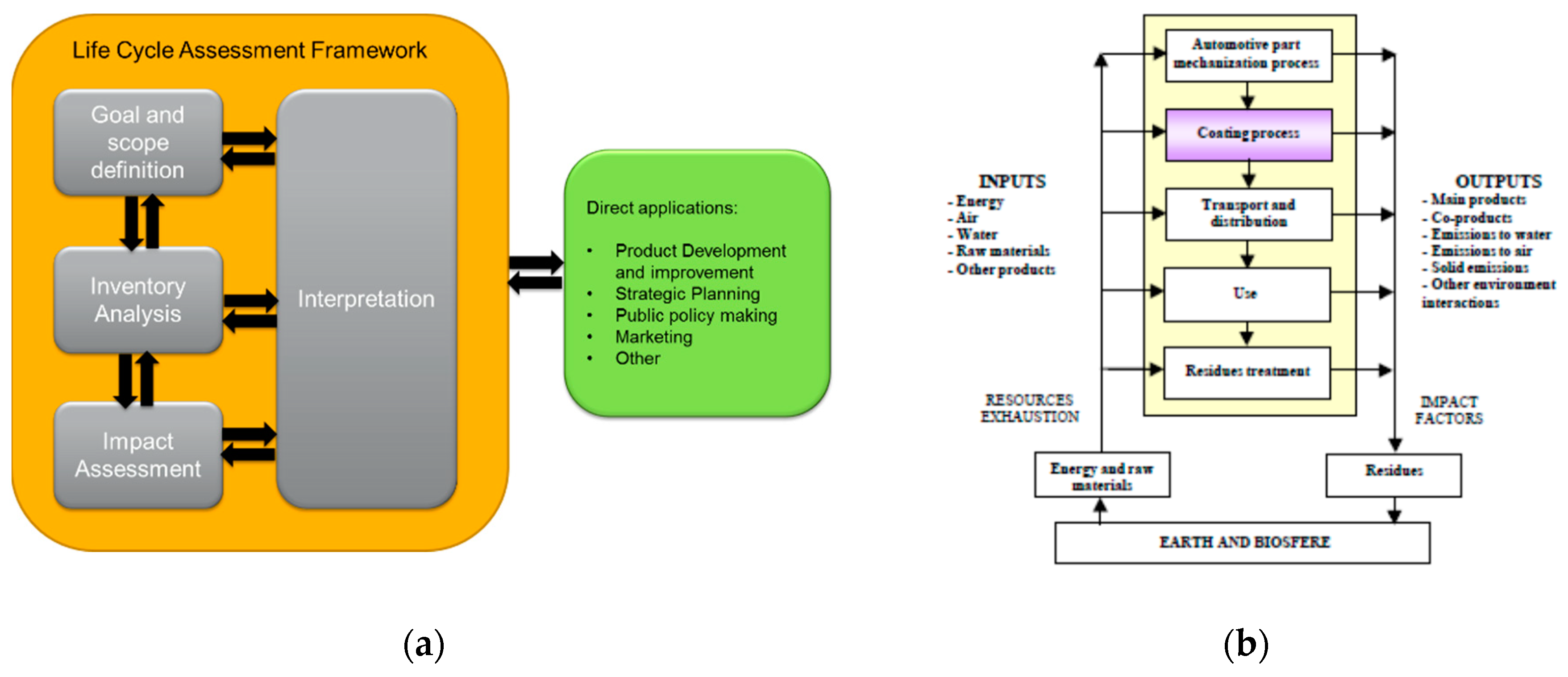
According to ISO 1404X, LCA addresses the environmental aspects and potential environmental impacts (e.g., use of resources and the environmental consequences of releases) through the products lifecycle from raw material acquisition through to production, use, end of life treatment, recycling and final disposal. The LCA study includes the four phases represented schematically in Figure 1a including (a) definition of the goal and scope, (b) inventory analysis, (c) impact assessment, and (d) interpretation of the results.
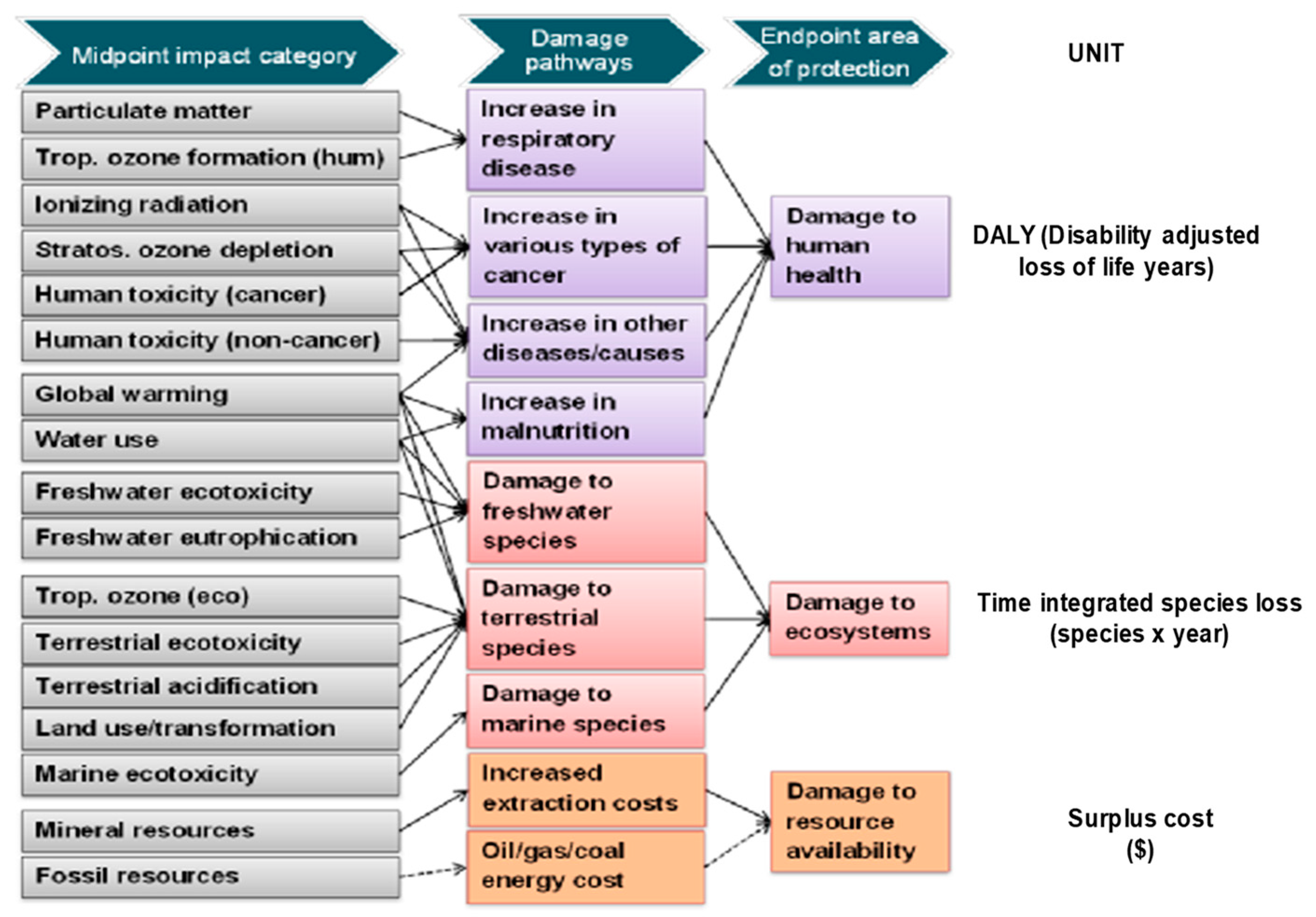
There are different specialized software packages on the market that help to assess the environmental lifecycle impact. For this study the SimaPro 9 software and the ReCiPe (Endpoint (H) V1.03/ Word 2010 H/A) methodology were selected for the impact evaluation methodology, since they cover the damage to human health, damage to ecosystems and damage to resource availability as end points. The primary objective of the ReCiPe method is to transform the long list of Life Cycle Inventory results (emissions, energy and resource extractions) into a limited number of impact assessment scores. These indicators express the relative severity of an environmental impact category. In ReCiPe, the impact assessment scores are determined at two levels: (a) at the midpoint level and at the endpoint level. As shown in Figure 2, ReCiPe calculates: (a) 18 midpoint indicators and (b) 3 endpoint indicators:

3. Surface Treatments Solutions for Engine Cylinder Liners

Within the framework of the EU EFCAP project, the potential use of PVD coatings and clean- chromium coatings as cylinder liners to replace Cr(VI) coatings was assessed using uncoated or nitride solutions as counter materials for piston rings.

3.1. PVD Coating Deposition and Basic Characterization

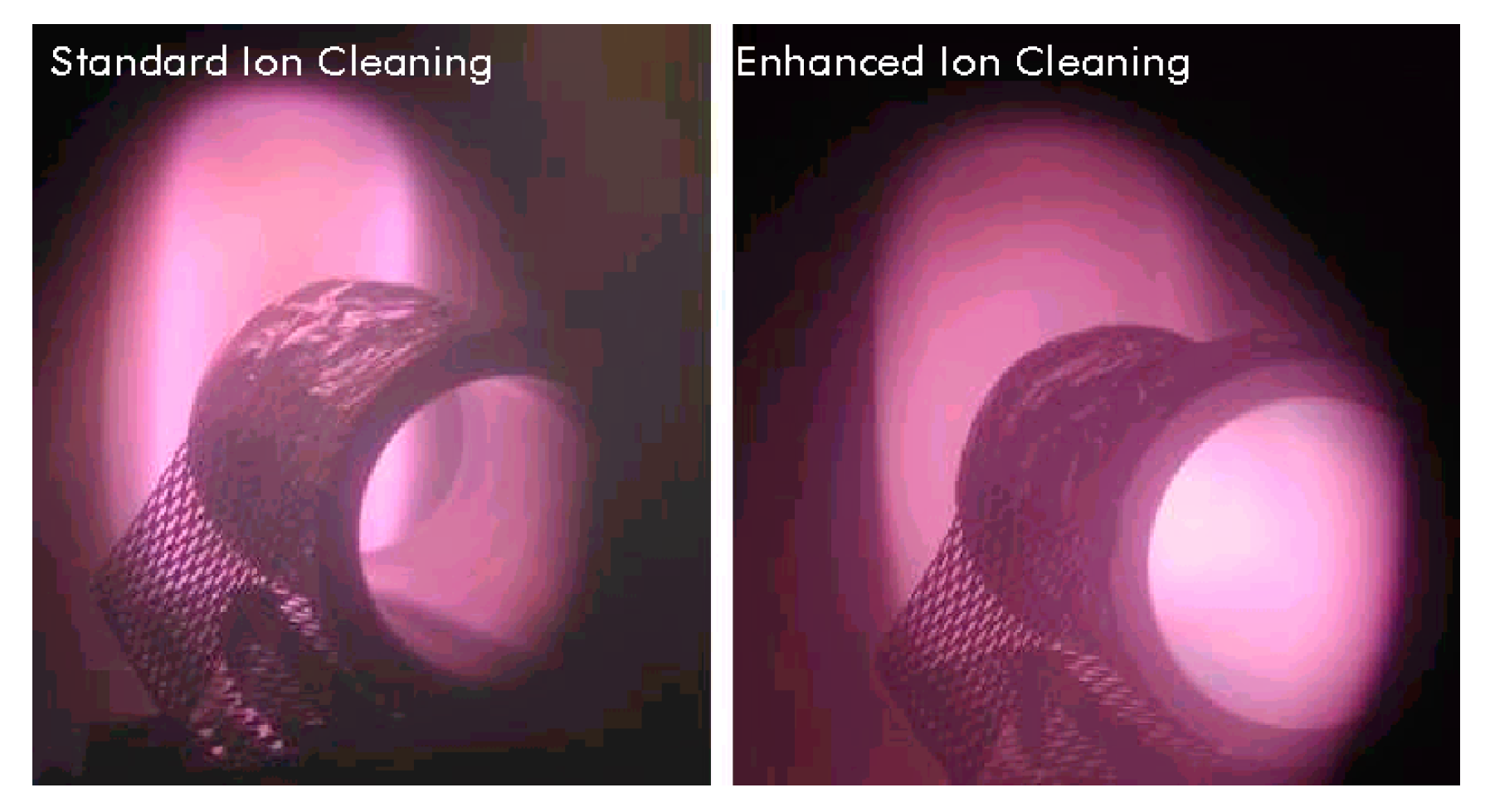
Cylinder liners and test samples were coated using magnetron sputtering. In order to achieve the necessary adherence on the internal side of the cylinder it was necessary to tune up the process conditions by applying extra cleaning to achieve sufficient plasma penetration inside the cylinder. Figure 3 (right) shows the plasma penetration of an enhanced ion cleaning method. The ion cleaning process enables coating adhesion to pass the 150 kg limit in the Rockwell indentation adhesion test [14].
Coatings were deposited onto ST52 steel cylinder liners (85 mm internal diameter (ID) and 205 mm length). The coating process could be performed from both ends of the cylinder liner. Most of the wear occurs on the hot side of the cylinder at the top dead center (point of minimum piston ring linear speed), and boundary lubrication conditions. The engine components were modelled and studied in detail by the authors for different type of coatings applied to piston rings during the EU Powerful project [15]. Due to the difficulty of coating the internal side of the cylinder using PVD, it was decided to coat the component from one single side only (the hot side), generating a thickness gradient of 10 µm on the near side of the plasma and of 1 µm on the far side. Laboratory test samples were prepared from the real cylinder liner, so the curvature of the cylinder was preserved.
Several coatings were deposited during the EFCAP project [16]: chrome-plated coatings were deposited by Cromo Duro company, while CrN and CrNi were applied by PVD magnetron sputtering by Gencoa. The NiCr and Ti/TiN coatings were applied by Salford University. A ball cratering test was used, together with metallographic preparations, for thickness determination [17].

3.2. Tribological Tests

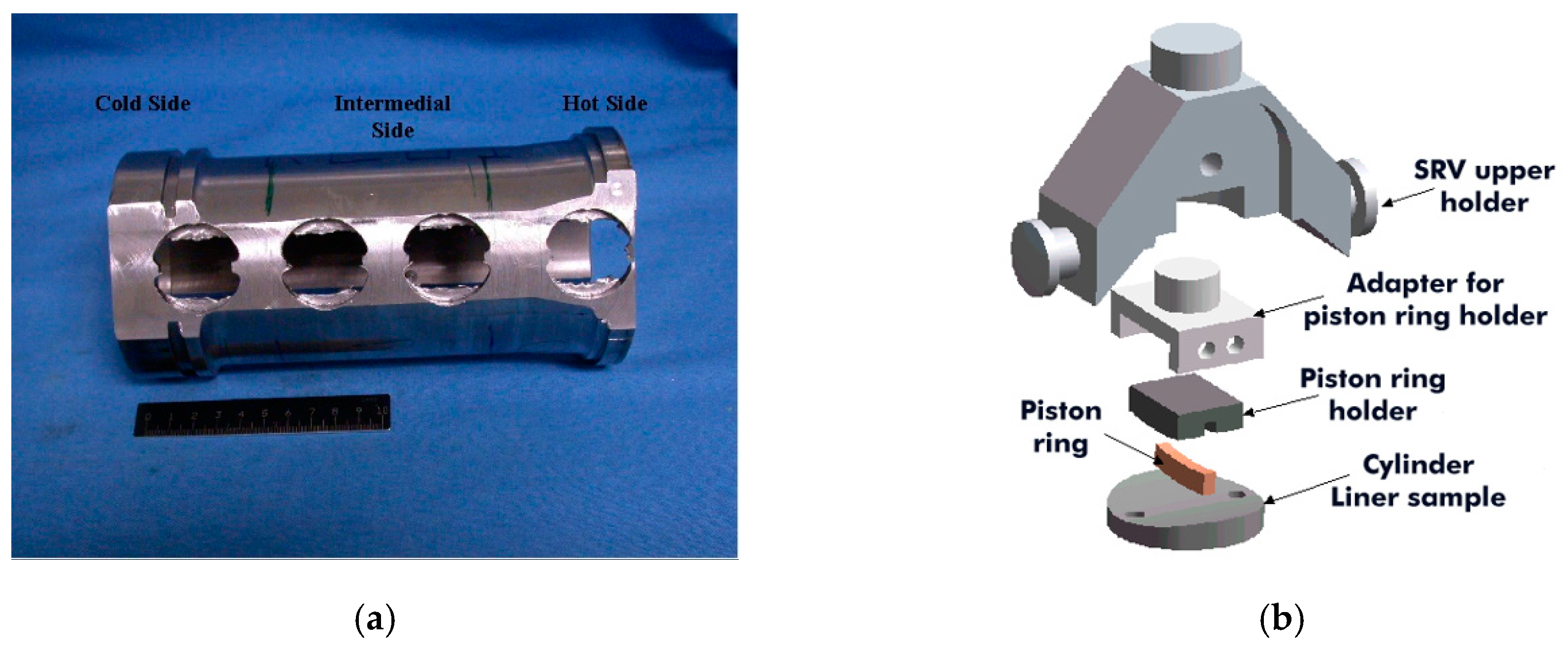
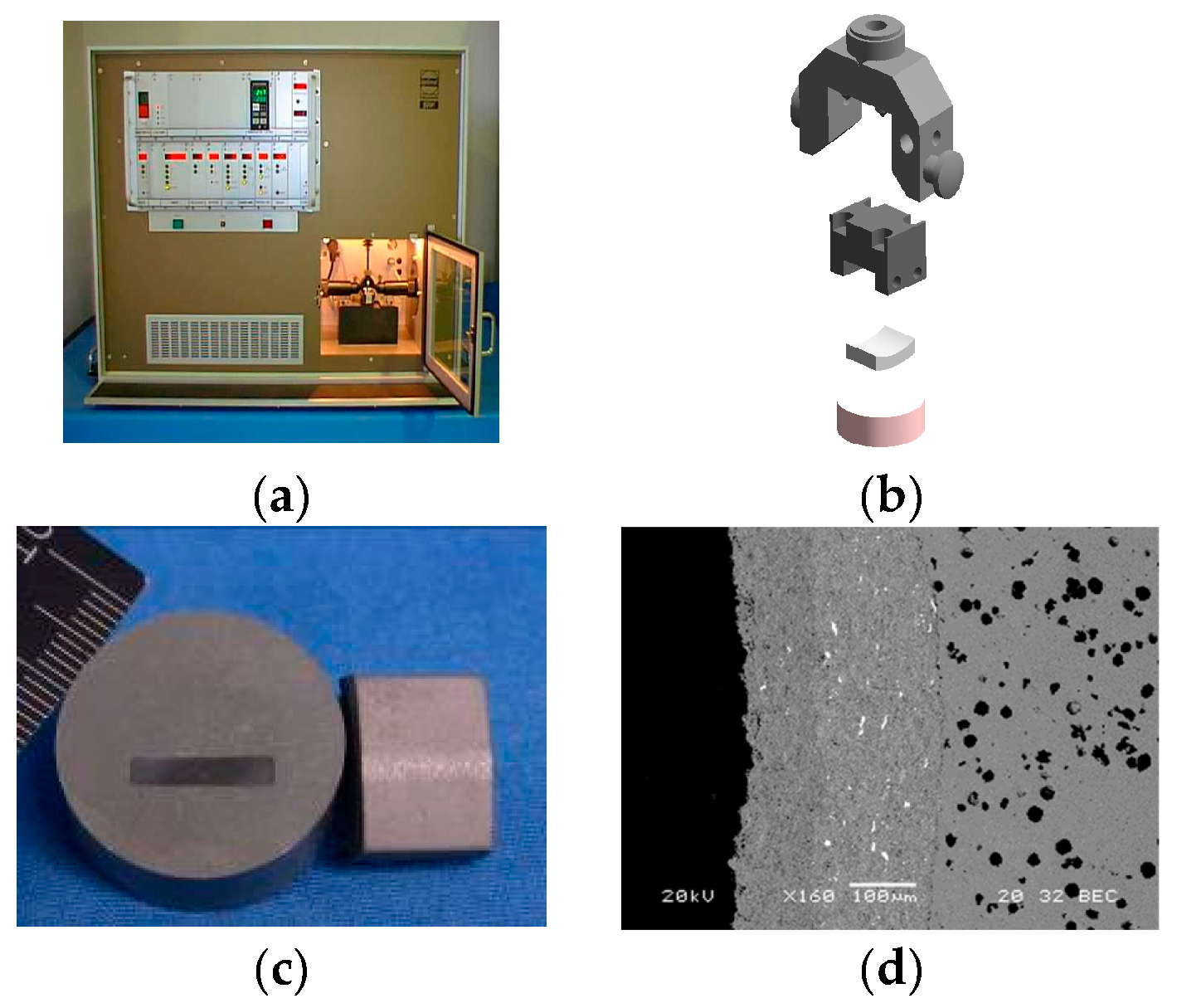
Laboratory tribological tests were carried out at TEKNIKER using an Optimol SRV-3 tribometer. Tests of the cylinder liners were carried out using a piston ring as the counterpart, applying a 300 N load in a reciprocated test with 50 Hz frequency and 3 mm stroke. The temperature was maintained at 150 °C using SAE 15W40 oil as the lubricant. The test duration was 1.5 h. The coated cylinder liner was cut out to get samples for different tests. Figure 4a shows a cylinder after samples were cut out for tribological tests. The tribological test assembly holder can be seen in Figure 4b. The data for the friction coefficient and wear in the piston ring and cylinder liner were compared. The chosen counterpart was an uncoated and nitrided cast iron piston ring [6,7,8].
Firstly, the ion cleaning effect was studied in terms of the roughness and tribological properties. The roughness was lower with the enhanced ion cleaning method, which also reduced the differences between the hot and cold sides to 0.06 µm. Test samples from the hot and cold sides of the cylinder were generated. Tribological testing was performed against a nitrided piston ring, with similar tribological performances being observed (Table 1).
After checking the suitability of the coating process protocol for CrN coatings, the other coatings were applied and tested. The results are shown in Table 2. When using uncoated and nitrided piston rings, the lower friction coefficient and wear was achieved for the NiCr and CrN PVD-coated cylinder liners, significantly reducing the piston ring wear compared with the chrome-plated reference. The cylinder liner coated with CrNi suffered slightly more wear than the cylinder liner coated with CrN, but the wear was significantly lower than for the uncoated sample. The chrome-plated and Ti/TiN-coated cylinder liners induced higher wear in the piston ring.

3.3. Scuffing Tribological Testing

Extreme pressure tests were carried out in order to evaluate the load-carrying properties of the tribosystem when increasing the pressure in the tribocontact. In this case, nitride piston rings were used with oil SAE 15W40 oil as the lubricant. A load of 50 N was applied during 2 min of operation, then the load was increased in 100 N increments, every 2 min until failure occurred or until reaching 2000 N. The applied stroke was 3 mm, the temperature was 150 °C, and the frequency was 50 Hz, with a linear speed of 0.3 m/s. The failure was considered when the total wear (piston ring + cylinder liner) reached the value of 1000 μm or when the machine has not enough power to reach the pre-fixed value of stroke (3 mm), due to an increase of the friction coefficient. The results of the tests are shown in Table 3.
The highest load without failure was 1300 N, which corresponded to a maximum time to failure of 1600 s. The maximum load-carrying capacity was achieved for CrN- and NiCr-coated cylinders against nitriding piston rings. CrN PVD coating was selected for the engine tests due to their industrial scale availability.
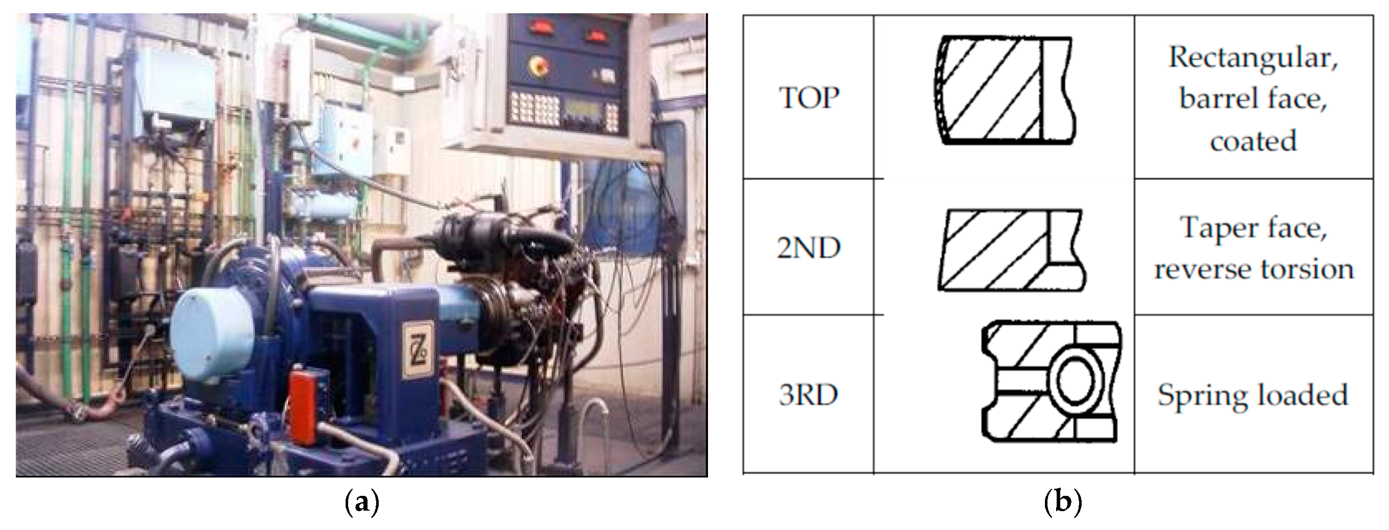
3.4. Engine Tests

Engine tests were carried out by Qinetiq (https://www.qinetiq.com) with a Ford Cortina engine. Oil consumption and mass losses on pistons and rings were monitored during the engine tests. The final engine tests were performed using selected piston ring and cylinder liner combinations, as shown in Table 4. A total of 4 piston rings were used on each piston. After 30 min of engine operation, oil consumption was measured. The oil level was also controlled after 50 h running and restored (if needed). The test ran for 100 h, after which the oil consumption and wear on piston rings, cylinder liners and pistons were measured. The oil consumption was indicated on the sealing surfaces of cylinders and piston rings. This oil consumption was affected by the wear and by the gradient thickness of the CrN coating (from 10 µm on the near side of the plasma to 1 µm on the far side). The lowest oil consumption corresponded to the clean-chrome-plated cylinder liner with nitrided piston rings while the highest consumption corresponded to the uncoated components.
After 100 h of testing, all rings had free movement (were not stuck). Pistons presented some scuffing for the uncoated combination (Test 1) while the coated and nitrided systems (tests 2 and 3) showed no scuffing on the piston, although some scoring appeared in test 2 (CrN + nitrided piston rings). Table 5 presents the mass losses on the pistons for the three different tests. The filling of carbon dust on the piston grooves was also analyzed. The three lower ring grooves did not have any carbon filling in any of the three tests. Tests 1 and Test 3 showed 19% of carbon filling in Groove number 1 (G1) while test 2 (CrN + nitrided piston rings) showed only 7% of carbon filling in G1. Values for the wear on piston rings are presented in Table 5 where it is evident that the combination of clean-chrome- plated cylinder liner and nitrided piston ring gave the lowest wear. Wear on the cylinder liner on the thrust side, at the hot end, was measured after 100 h of testing, showing again that the lowest wear result were achieved for the chrome-plated cylinder liner in terms of both depth and length. The lack of thickness homogeneity in the CrN coating might be one of the reasons for the slightly higher wear.

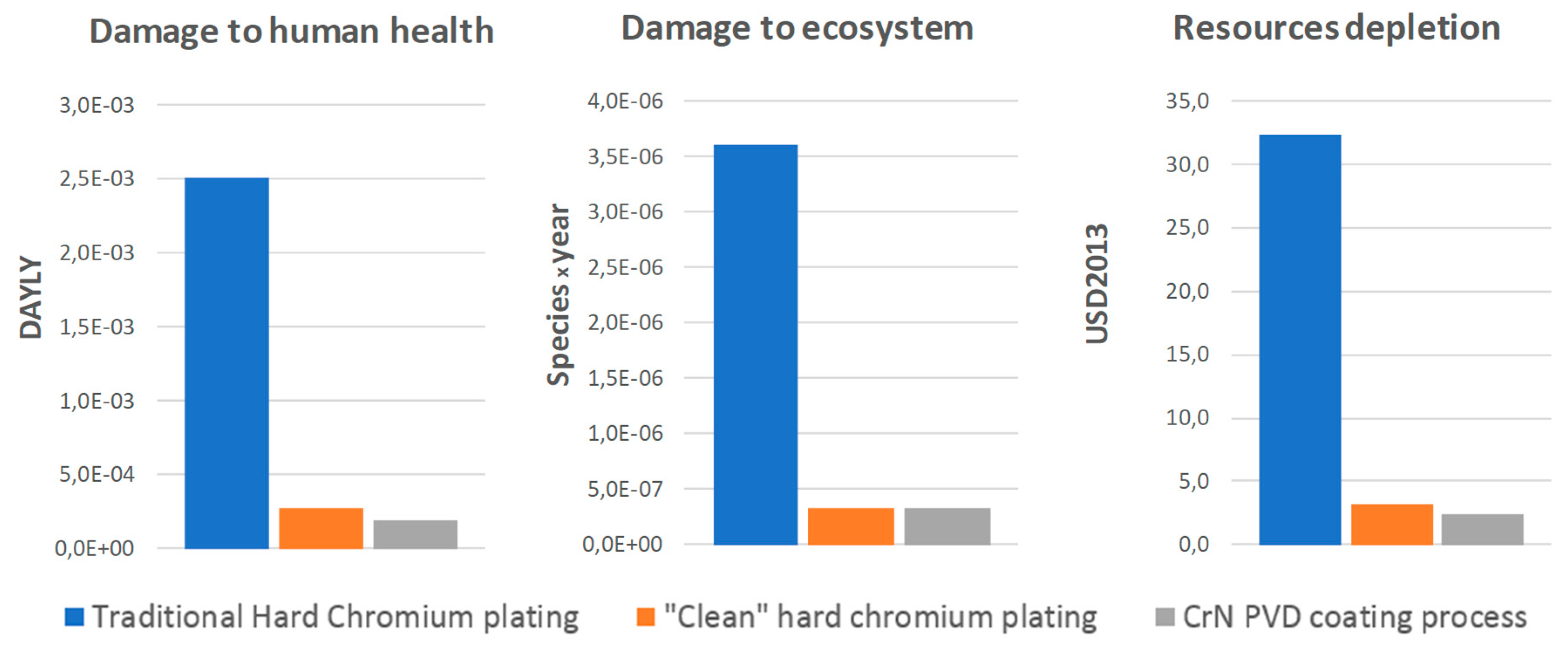
3.5. Lifecycle Environmental Assessment

Manufacturing of cylinder liners as with any other product, has an impact in the environment, caused by raw material extraction, manufacturing, distribution and use to end of life (disposal, recycling and reuse processes). The aim of this study was to compare the environmental performance of three cylinder liners coated with different coatings; including CrN PVD and 2 hard chromium plating processes: (a) a traditional chrome plating method used before the year 2000 and (b) a second process, called “clean” hard chrome plating introduced by Cromo Duro company in the year 2000. The analysis focused on the coating deposition process itself, while the other cylinder liner life cycle steps were considered outside of the system limits. The functional unit selected was 1 m2 coated surface area of component. The environmental profiles of the three deposition processes, related to the 3 areas of protection considered in ReCiPe 2016 (human health, ecosystems and resources scarcity) are compared in Figure 5.
The environmental profiles were calculated considering the following three criteria:
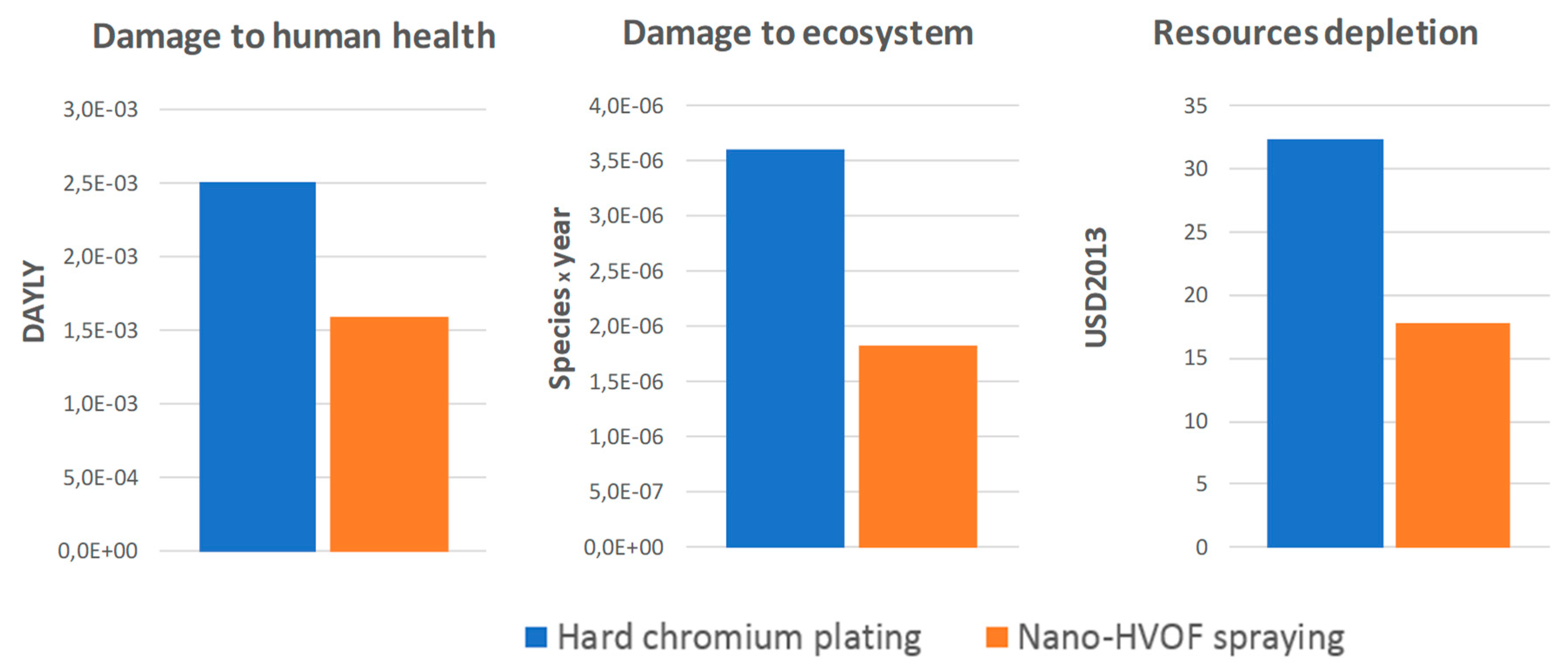
  • Disability adjusted life years (DALYs) relevant for human health, represent the years that are lost or that a person is disabled due to a disease or accident.
  • The unit for ecosystem quality is the local species loss integrated over time (species year).
  • The unit for resource scarcity is the dollars ($), representing the extra costs involved for future mineral and fossil resource extraction.
The values for the environmental loads of traditional hard chrome are much higher than those for a PVD process such as a CrN process. However, the chrome industry has been moving fast in the last few years in order to improve this situation. The environmental impacts of the “clean” hard chrome plating coating process were very similar to those found for CrN PVD. The detailed analysis of the environmental impacts shows that for the “clean” and traditional hard-chrome-plated, the highest environmental load is related to the chemicals used in the process (around 60% of the total impact) followed by the electric energy consumption (39%). For the CrN PVD coating, the main impacts were due to the electricity (62%) and the raw materials, such as the chromium blank used in the process (34%). However, technologically both coating processes would result in a very similar environmental load, therefore the final use of either method would have to respond to issues of production costs, technical performance and scaling optimization.
Although PVD coatings offered an alternative to traditional chrome plating due to environmental impact considerations, the latest advances in the chrome plating processes have matched the values of process “cleanliness”. When testing PVD and chrome plating coatings in laboratory conditions, it was possible to obtain better results for PVD coatings in terms of friction and wear. Engine tests showed that the chrome-plated cylinder liners performed better than the CrN-coated ones. This difference seems to be related to the difficulty of depositing homogeneous coatings inside the cylinders (9 µm difference), being this difference more significative when testing the complete component than in small samples. Both, a lifecycle environmental assessment, and lifetime characterization (tribological and engine testing) are needed to design surface technologies for sustainable products and processes.

4. Surface Treatments Solutions for Piston Rings

Within the framework of the EU Nano-HVOF project, the potential use of nanopowders in high velocity-oxyfuel processes were investigated as a solution to substitute Cr(VI) coatings for piston rings [16]. These coatings were also compared with PVD solutions. A screening of the tribological properties was done at basic, simulated and engine testing levels. Additionally, a lifecycle environmental assessment comparing the production processes of the new coating alternatives, with the reference chrome-plated process was addressed and the overall results described.

4.1. Coating Deposition

The coatings studied were deposited on testing samples made of the piston ring substrate (spheroidal graphite cast iron), using the HVOF thermal spray process. The feedstock powder used were commercially available by WOKA company (now Oerlikon Metco). Their composition was 2075-NiCr (Cr2C3 75% + NiCr20 25%) and WC86-Co10Cr4. The 2075-NiCr powder was mechanically treated to obtain nano powders. Later, the HVOF thermal spray process was used to produce conventional and nanocrystalline Cr3C2-NiCr coatings by Thermico. A detailed study of the metallography and hardness properties of the powders and coatings is described elsewhere [18]. The coatings were compared with PVD coatings deposited by TEKNIKER and Ni-composite coatings and Cr plated coatings supplied by the company CIE Automotive (Tarabusi) [19]. The Table 6 summarizes the composition, thickness, hardness and roughness values of the layers.

4.2. Cylinder-on-Disc Tribological Tests

First, tribological tests were carried out by TEKNIKER using a “cylinder-on disc” basic configuration (Figure 6) in order to compare the friction and wear behaviors of the 75Cr3C2-25NiCr coatings with small powder size in relation to the standard 75Cr3C2-25NiCr//WC86-Co10Cr4 coating and the reference electrolytic chrome plating. The different coatings deposited on the samples of the piston ring material (cast iron), were tested using the cylinder liner material as counter material under lubricated test conditions: (a) nominal load = 200 N, (b) speed = 50 Hz, (c) stroke = 1 mm, (d) temperature = 100 °C and (e) time = 60 min, using a SAE 15W-40 lubricant as the reference oil. The results are represented in the Table 7.
As a result of these tests we can see that the surface roughness is in general the most critical parameter which is determining the friction and wear properties under lubricated conditions. The friction and wear properties of the different HVOF coatings improve considerably when the roughness is reduced by means of a grinding process. The reduction of the powder size in the 75Cr3C2-25NiCr coating produces an important reduction in the coating roughness and consequently, an improvement in the friction and wear properties. The differences between the coatings are not significant when the coatings are ground. The 75Cr3C2-25NiCr coating presented better wear properties than the alternative WC86-Co10Cr4 coating.

4.3. Piston Ring-Cylinder Liner Tribological Tests

The tribometer simulates the sliding reciprocating motion between the piston ring and piston wall in an operating engine using the same piston ring-cylinder liner configurations shown in Figure 4. The piston ring moves in the same groove as the real engine piston. The piston ring segments were submitted to a reciprocating motion with a stroke of 3 mm and an oscillating frequency of 50 Hz. normal load applied was 50 N during a short run-in period (30 s) and 300 N during the complete test duration (90 min). During the test, the piston ring segment and the cylinder liner sample were immersed in the oil at a constant temperature of 200 °C, using the SAE 15W-40 reference oil. The diamond-like PVD coating deposited on tungsten carbide called “WC-C” had a lower friction coefficient and wear rate, probably caused by the low roughness (0.065 µm). The newly developed coatings “A” (Nano 75Cr3C2-25NiCr) and “D” (75Cr3C2-25NiCr) had better friction and wear properties than the reference chrome-plated piston ring. However, when changing the composition to the WCCoCr/ Cr3C2-NiCr (coating “B”), poor results were obtained. Large abrasive wear particles remained in contact causing an important increase in the friction and wear. When reducing the powder size (<10 µm), the coated piston ring presented significantly better behavior than piston ring with larger-sized powder. In addition, the NiPCO+Si3N4 and TiN-CrN coatings had better friction and wear properties than the reference chrome-plated piston ring [19]. The results are represented in the Table 8.

4.4. Engine Tests

Finally, engine tests were carried out by the company CIE Automotive Group to compare the behavior of developed coatings with reference piston rings coated with chrome and nitrided steel. For this purpose, a turbodiesel engine was selected, where the reference and developed coatings have been tested at full load and high temperature. For assessment purposes, the wear levels of the cylinder block (bore), piston (first groove sides corresponding to the top ring) and piston ring (face and sides) and fuel consumption were used. Wear and fuel consumption results were judged favorably for both developed coatings. The lower wear was observed for the CrN/TiN PVD coating followed by the CrN coating, the WC/C and 75Cr3C2-25NiCr coatings and the NiP+Si3N4 coatings. The lowest fuel consumption was obtained with the NanoHVOF coating and the WC/C PVD coatings. The engine employed for this task (Figure 7) was a 4-stroke water-cooled direct injection turbodiesel engine, with the following characteristics: (a) bore = 90 mm, (b) stroke = 90 mm, (c) displacement = 2 dm3, (d) power = 50 kW at 3000 rpm, (e) maximum torque = 172 Nm at 1800 rpm. In order to compare results, 8 different tests were carried out, with 2 using reference coatings (chromium over spheroidal graphite cast iron and gas nitriding of steel), while the other combinations included the previously described coatings.

4.5. Heat Endurance Tests

The parameters applied in all the tests to assess the functional behavior were the scuffing resistance and wear resistance tests. Wear evaluation after engine testing was performed on piston ring coatings and on the contact surfaces of pistons and blocks (cylinder bores), namely: (a) piston ring faces (measured as closed gap increases); (b) piston ring sides (height decreases) (c), sliding surfaces of cylinder bores (bore diameter increase in the top dead center position of the first ring) and d) piston top groove sides (groove height increases). The aim was to prevent from the occurrence of piston ring sticking and measure the wear of the involved parts. The test conditions were: (a) torque = 167 Nm, (b) Speed = 3000 rpm, (c) water temperature = 110 ± 5 °C, (d) Oil temperature: 130 °C maximum. The wear test results are displayed in Figure 8a. It was demonstrated that the wear results showed the same trend as measurements based on closed gap increases. Additionally, at the end of heat endurance tests, fuel consumption measurements were performed, using the AVL 733 S device. The obtained values are plotted in Figure 8b. The engine tests confirmed the previous results, namely that it is possible to select CrN/TiN PVD coatings from the point of view of wear and 75Cr3C2-25NiCr nanocoatings from the point of view of fuel consumption (Figure 8c).
Engine tests confirmed the previous tribological results, namely that it is possible to select the CrN/TiN PVD coating that exhibited a minimum wear and 75Cr3C2-25NiCr nanocoating that minimized the fuel consumption. The nano-75Cr3C2-25NiCr allowed a reduction of 50% in the coating thickness when compared to chromium. This translates into reductions of powder cost and grinding needs. The diamond-like WC/C coating deposited by PVD also showed a good compromise between wear, friction and low fuel consumption. The advantage of the PVD coating is that it is possible to deposit a thin layer of around 8 µm at the last step in the piston ring manufacturing process while maintained the shape of the piston ring [19].

4.6. Lifecycle Environmental Assessment

Using the protocol described in Section 2 and Section 3.5, the lifecycle environmental assessment of the two piston ring coating processes (the hard chromium plating and the nanoHVOF spraying) were analyzed and compared. As functional unit, 1 m2 coated surface areas of the piston rings were also considered. The environmental evaluation results are summarized in Figure 9.
The nanoHVOF spraying process resulting in considerably lower environmental impacts than the hard chromium plating in the three areas of protection considered (36% reduction in damage to human health, 50% reduction in damage to ecosystems and 45% reduction in resource scarcity) but was higher than PVD coatings (Figure 5). Analyzing more deeply the nanoHVOF process, the main impacts were due to the nanopowder manufacturing process (66%), while the impacts associated to the gases and kerosene used in the process (18%) were also important. In a similar way in the hard chromium plating process, the main impact was due to the electricity consume (54%).
The results of the environmental impact test show that it is possible to reduce the environmental impact when using alternative substrate treatments to traditional Cr(VI) coatings, such as HVOF and PVD.

5. Conclusions

HVOF and PVD coatings can be good alternatives to traditional Cr(VI) chrome-plated methods from both performance and environmental impact perspectives. It is also possible to develop clean-chrome-plating processes, reaching very low levels of environmental impacts. Lifecycle assessment is a very important tool to evaluate and reduce the environmental impact of a process, and the use of such tools could be more relevant to regulate the environmental impact, instead of limiting the use of some chemicals. In the future, the data from the tribological and engine tests could be also be integrated into the lifecycle studies to assess the impacts of increasing the durability during use at the design phase of products and processes.

Author Contributions

Conceptualization, original writing and funding (A.I.), PVD coatings (A.A.), R.B. (unit management), G.M. (LCA), X.F. (tribological tests), B.Z. (engine tests revision), and A.A. (supervision). All authors have read and agreed to the published version of the manuscript.

Funding

The APC was funded by EU Commission.

Acknowledgments

The authors would like to acknowledge the European Commission for the financing of the European Projects EFCAP and NanoHVOF under contracts G3ST-CT-2001-50097 and G5RD-CT-2000-00231, respectively. The authors would like to acknowledge also to the main participants of the project, for contributing to the results, namely Eltro, Qinetiq, CIE Automotive, Tarabusi, Cromo Duro, Gencoa, FCA (CRF), Thermico, and the rest of the partners that agreed to publish the results. The authors would like to specially acknowledge the contribution from J. Landa, I. Illarramendi, M. Bolton, V. Vellido, E. Momeñe and MG. Talks. Finally, authors would like to acknowledge the chief editor A. Zhu and MDPI experts for the revision.

Conflicts of Interest

The authors declare no conflict of interest.

References

  1. Wynn, P. The End of Life Vehicle Directive and International Material Data System-Their implications for surface finishing. Prod. Finish. 2003, 67, 58–69. [Google Scholar]
  2. Sorahan, T.; Harrington, J.M. Lung cancer in Yorkshire chrome platers, 1972–1997. Occup. Environ. Med. 2000, 57, 385–389. [Google Scholar] [CrossRef] [PubMed] [Green Version]
  3. Hexavalent Chromium. Available online: https://www.serdp-estcp.org/Featured-Initiatives/Green-Manufacturing-and-Maintenance/Hexavalent-Chromium (accessed on 2 November 2019).
  4. Huijbregts, M.A.; Steinmann, Z.J.; Elshout, P.M.; Stam, G.; Verones, F.; Vieira, M.; Zijp, M.; Hollander, A.; van Zelm, R. Recipe2016: A harmonised life cycle impact assessment method at midpoint and endpoint level. Int. J. Life Cycle Assess. 2017, 22, 138–147. [Google Scholar] [CrossRef]
  5. Woydt, M. Tribology in Germany. Available online: https://www.gft-ev.de/wp-content/uploads/GfT-Study-Tribology-in-Germany.pdf (accessed on 2 November 2019).
  6. PVD Coating for Cutting Tools—Superior Tool Service. Available online: https://superiortoolservice.com/pvd-coating (accessed on 2 November 2019).
  7. Metallisation Ltd. | Thermal Spary Solutions. Available online: https://www.metallisation.com/applications/hvofalternativestohardchromeplating (accessed on 2 November 2019).
  8. Oerlikon, PVD Coatings as Replacement for Hard Chrome on Components. Available online: https://www.sme.org/technologies/articles/2019/september/pvd-coatings-as-replacement-for-hard-chrome-on-components (accessed on 2 November 2019).
  9. HVOF as Your Hard Chrome Replacement. Available online: http://www.surfacetechnology.co.uk/time-reach-hvof-hard-chrome-replacement (accessed on 2 November 2019).
  10. Igartua, A.; Fernández, X.; Areitioaurtena, O.; Luther, R.; Seyfert, C.; Rausch, J.; Plouseau, S. Biolubricants and triboreactive materials for automotive applications. Tribol. Int. 2009, 42, 561–568. [Google Scholar] [CrossRef] [Green Version]
  11. HVOF Coating as an Alternative to Hard Chrome. Available online: https://www.cts-inc.net/resources/hvof-coating-as-an-alternative-to-hard-chrome (accessed on 2 November 2019).
  12. A Union That Strives for moreMy Agenda for Europe. Available online: https://ec.europa.eu/commission/sites/beta-political/files/political-guidelines-next-commission_en.pdf (accessed on 2 November 2019).
  13. Igartua, A.; Bayon, R.; Aranzabe, A.; Laucirica, J. Tribology: The Tool to Design Materials for Energy-Efficient and Durable Products and Process. In Friction, Lubrication and Wear, Mohammad Asaduzzaman Chowdhury; IntechOpen: London, UK, 2019. [Google Scholar]
  14. Testing Equipment—PVD Coatings. Available online: https://www.pvd-coatings.co.uk/pvd-coating-technology/testing-equipment/rockwell-adhesion-tester (accessed on 2 November 2019).
  15. Zabala, B.; Igartua, A.; Fernández, X.; Priestner, C.; Ofner, H.; Knaus, O.; Abramczuk, M.; Tribotte, P.; Girot, F.; Roman, E.; et al. Friction and wear of a piston ring/cylinder liner at the top dead centre: Experimental study and modelling. Tri. Int. 2017, 106, 23–33. [Google Scholar] [CrossRef]
  16. UNE-EN ISO 1463:1996. Available online: https://www.une.org/encuentra-tu-norma/busca-tu-norma/norma/?c=N0033115 (accessed on 2 November 2019).
  17. Bellido-González, V.; Igartua, A.; Mendoza, G.; Powell, S.; Talks, M.G.; Momeñe, E. Replacement of hard-chrome in cylinder liners. A PVD approach. Soc. Vac. Coaters 2004, 505, 856–7188. [Google Scholar]
  18. Picas, J.A.; Forn, A.; Igartua, A.; Mendoza, G. Mechanical and tribological properties of high velocity oxy-fuel thermal sprayed nanocrystalline CrC-NiCr coatings. Surf. Coat. Technol. 2013, 174–175, 1095–1100. [Google Scholar] [CrossRef]
  19. Landa, J.; Illarramendi, I.; Montalban, J.M.; Igartua, A.; Mendoza, G. Wear and friction in piston rings. In 1st COST 532, Superior Friction and Wear Control in Engines and Transmissions; Congress Proceedings: Ghent, Belgium, 2004; pp. 86–100. [Google Scholar]
Figure 1. (a) Stages or phases of the lifecycle assessment (LCA). (b) The lifecycle stages are analyzed by considering energy and raw material transformations during the coating processing of an automotive component.
Coatings 10 00634 g001
Figure 2. Overview of the impact categories that are covered in the ReCiPe methodology and their relationships to the damage to human health, damage to ecosystems and resource availability are highlighted [4].
Coatings 10 00634 g002
Figure 3. Photo shots (Gencoa, https://www.gencoa.com/) of cylinder liners in front of a Cr target during ion cleaning. The standard ion cleaning (left) does not allow plasma penetration, whilst the enhanced ion cleaning (right) allowed the desired penetration.
Coatings 10 00634 g003
Figure 4. (a) Photo of the cylinder liner with cut outs made for tribological test samples. (b) Tribological test assembly for cylinder liner samples, designed by TEKNIKER© to adapt to the SRV machine. Piston ring holder, piston ring, and cylinder liner samples were extracted from the original components.
Coatings 10 00634 g004
Figure 5. Environmental profile of three coating processes: traditional chrome plating, new clean chrome plating and CrN PVD. Impact evaluation method: ReCiPe [4].
Coatings 10 00634 g005
Figure 6. (a) SRV machine, (b) Cylinder-on-disc test configuration, (c) testing specimens and (d) nano-HVOF coating micrograph.
Coatings 10 00634 g006
Figure 7. (a) The engine arrangement in the test bed [19]. (b) The piston ring set is composed of three units—two compression units and one oil control unit.
Coatings 10 00634 g007
Figure 8. (a) Piston ring and cylinder wear under heat endurance test conditions: (1) closed gap increase, (2) bore diameter increase in top dead center position of the first ring. (b) Piston ring wear under heat endurance test conditions. (c) Fuel consumption measurements, CIE Automotive (Tarabusi).
Coatings 10 00634 g008
Figure 9. Comparative LCA of the traditional hard-chromium-plating and nano-HVOF spraying methods. Impact evaluation method: ReCiPe.
Coatings 10 00634 g009
Table 1. Enhanced ion cleaning effects on roughness and tribological performance.
-Hot SideCold Side
-Roughness µmFriction µWear (mg) Cylinder/PistonRoughness µmFriction µWear (mg) Cylinder/Piston
Standard cleaning0.520.1691.34/0.240.36 0.1700.7/0.1
Enhanced ion Cleaning0.490.1741.06/0.310.430.1690.56/0.04
Table 2. Tribological test data for different combinations of cylinder liners and piston ring tribotests.
Cylinder Liner Piston RingAverage Friction CoefficientCylinder Liner Mass Loss (mg)Piston Ring Mass Loss (mg)Wear (mm)Wear Scar
Chrome-platedUncoated0.186-69.140.548 Coatings 10 00634 i001
Uncoated0.26712.690.560.209 Coatings 10 00634 i002
CrN0.172-1.960.110 Coatings 10 00634 i003
Ti/TiN0,184-50.640.696 Coatings 10 00634 i004
CrNi alloy0.1831.00.510.147 Coatings 10 00634 i005
NiCr0.169-0.500.233 Coatings 10 00634 i006
Chrome-platedNitrided0.167-8.040.156 Coatings 10 00634 i007
Uncoated0.1672.10.180.120 Coatings 10 00634 i008
CrN0.168-2.060.139 Coatings 10 00634 i009
Ti/TiN0.164-13.040.227 Coatings 10 00634 i010
CrNi alloy0.1891.290.1330.143 Coatings 10 00634 i011
NiCr0.173-0.050.193 Coatings 10 00634 i012
Table 3. Extreme pressure test results for different cylinder liner coatings against nitrided piston rings.
Cylinder Liner CoatingTime at Which Failure OccursThe Highest Load without FailureType of FailureWear Scar
Chrome-plated880 s700 N High wear Coatings 10 00634 i013
CrN1600 s1300 NSevere Stroke reduction Coatings 10 00634 i014
Uncoated1507 s1200 N Severe Stroke reduction Coatings 10 00634 i015
Ti/TiN1378 s1100 NSevere Stroke reduction Coatings 10 00634 i016
CrNi alloy1332 s1000 NSevere Stroke reduction Coatings 10 00634 i017
NiCr alloy1602 s1300 NSevere Stroke reduction Coatings 10 00634 i018
Table 4. Engine test surface condition for ST52 cylinder liners, cast-iron piston rings and oil consumption values.
Cylinder LinerPiston RingsOil Consumption (G/H)
Test 1UncoatedUncoated62.50
Test 2Crn CoatedNitrided30.29
Test 3Clean-Chrome-PlatedNitrided17.31
Table 5. Engine test: mass loss on pistons, piston rings and cylinder liners.
-Mass Losses on Piston Rings (mg)Cylinder Liner Wear
Test (Cylinder Liner/Piston Ring)Piston Mass Loss (g)R1R2R3R4Wear Depth (µm)Worn Length (mm)
Test 1 (Uncoated/Uncoated)6.5620131337< 2022
Test 2 (CrN coated/Nitrided)−0.182037740-3< 520
Test 3 (Chrome-plated/Nitrided)−0.76177225< 36
Table 6. Chemical, thickness, hardness and roughness analysis of the different coating processes.
Coating ProcessPiston Ring CodeCoating CompositionThickness (mm) UNE-EN ISO 1463: 1996Layer Hardness UNE-EN ISO 6507Roughness (µm)
HVOF“A” coatingNano-75 Cr3C2-25NiCr Power size –10 µm0.15 mm801 HV0.11
HVOF“B” coatingWC CoCr//CrC-NiCr Power size -30+10 µm0.19 mm1039 HV0.33
HVOF“D” coating75 Cr3C2-25NiCr Power size -45 +20 µm0.13 mm798 HV0.23
ElectrolyticNiPCO + Si3N4NiPCO + Si3N415 µm1057 HV0.245
PVDCrN/TiNTiN-Ti/CrN-CrN8.5 µm1965 HV0.175
PVDWC/CWC/C2.4 µm1052 HV0.065
Electro-depositionCrCr0.145 mm1136 HV1.21
Table 7. Cylinder-on-disc test results.
-Powder Size (µm)Roughness (Ra, µm)Average Friction CoefficientTotal Mass Loss (mg)
Coatings without grinding----
WC86-Co10Cr415–304.160.37522.17
75 Cr3C2-25NiCr Standard10–304.870.3909.39
Nano-75Cr3C2-25NiCr1.4–302.10,1951.03
Nano-75Cr3C2-25NiCr−101.810,1961.03
Nano-75Cr3C2-25NiCr−51.780,1871.9
Coatings after grinding----
WC86-Co10Cr415–300.50,1632.17
75 Cr3C2-25NiCr Standard10–300.50,1580.45
Nano-75Cr3C2-25NiCr1.4-300.30,1600.27
Nano-75Cr3C2-25NiCr−100.50,1670.30
Nano-75Cr3C2-25NiCr−50.40,1600.27
Electrolytic Cr Reference-0.50,1820.45
Table 8. Ring-cylinder liner friction and wear results with different coatings.
Deposition ProcessCoating CompositionFriction Coefficient (Average)Piston Ring Mass Loss (mg)
ElectrodepositionHard chrome0.160.2
ElectrolyticNiPCO+Si3N40.150.1
PVDTiN-Ti-CrN-CrN0.160.0
PVDWC-C0.130.0
HVOFNano-75Cr3C2-25NiCr Powder size < 10 µm0.150.1
HVOFWC-CoCr/CrC-NiCr Powder size 10 < x < 30 µm0.210.0
HVOF75Cr3C2-25NiCr Powder size 20 < x < 45 µm0.150.2

