Abstract
By virtue of plasma spray-physical vapor deposition (PS-PVD) process, coatings in possession of columnar structures can be obtained by suitable processing parameters coupled with specially designed powder feedstock. In this paper, the influence of powder characteristics on the La2Ce2O7 (LC) coating microstructures was investigated by using three kinds of feedstock powders with same PS-PVD processing parameters. It was found that small agglomerated feedstock, weak binding strength, and small primary particle sizes can enhance the feedstock evaporation rate, thus obtaining well columnar structured coatings. X-ray diffraction (XRD) patterns revealed that except for a very small amount of La2O3 the main phase of all the coatings is LC. The La/Ce atomic ratios reduced in the coatings compared to the feedstocks, especially the coatings with better columnar structure. Super-lattice patterns were observed by transmission electron microscope (TEM), which means that the LC phase is supposed to be pyrochlore structure. Furthermore, the mechanical properties evaluated by nano-indentation tests indicated that both the hardness and Young’s modulus of each coating show negative correlations with the porosity inside the columns.
1. Introduction
Plasma spray-physical vapor deposition (PS-PVD), a cutting-edge technology on the foundation of plasma spraying, has been regarded as an alternative technology to deposit thermal barrier coatings (TBCs) in possession of columnar structures [1,2], since yttria partially stabilized zirconia (YSZ) columnar coatings deposited via PS-PVD process have shown excellent performances as TBCs [3,4,5]. Compared to electron beam-physical vapor deposition (EB-PVD), PS-PVD enables not only more economic profit and higher deposition rate [6] but also non-line-of-sight deposition, hence probably achieving homogeneous TBCs deposition on intricate geometric components [7,8].
To realize vapor deposition by plasma spray method, it relies not only on the development of the facility, but also on specific feedstock powders [9]. Currently, a kind of YSZ powder, named M6700, is the only commercial powder specially for PS-PVD utilization [10,11,12,13,14]. The agglomerated particle sizes of M6700 are very small. Additionally, the inner structure of single particle of M6700 is quite loose and porous. Such characteristics of M6700 are beneficial to breaking the agglomerated particles into small primary particles and thus to achieve a high evaporation rate [9].
Due to the restriction of feedstock supply, PS-PVD coatings other than YSZ were hardly manufactured and investigated [15,16,17]. It cannot be denied that YSZ used as TBC is beyond comparison below temperature of 1200 °C [18,19]. However, the application of YSZ is limited due to accelerated sintering and phase transformation at higher temperatures [20,21,22]. La2Ce2O7 (LC) was proposed as alternative ceramic material for application at higher temperatures, since it can provide high phase stability below 1400 °C and very low thermal conductivity [23]. Previously, a double-ceramic-layer (DCL) LC/YSZ coating deposited by EB-PVD has shown a thermal cyclic lifetime of 2007 times at 1250 °C [24], which further demonstrated that columnar structured LC coatings have potential on TBCs application at higher temperature. In our previous investigation, LC coatings in possession of columnar structures have been achieved by PS-PVD [25]. However, the processing window was rather narrow because of the restriction of the feedstock [25]. Thus, it is necessary to investigate the influence of LC feedstocks and to further modify the feedstock for using in PS-PVD.
In this paper, three kinds of feedstock powders were synthesized and manufactured for comparing the influence of powder characteristics on the coatings’ microstructures. One of them has large agglomerated particle size close to air plasma spray (APS) powder in consideration that LC is one of the easiest to be vaporized materials among current TBCs candidates [26]. The other two have small agglomerated particle sizes like YSZ feedstock M6700 [9]. The primary particle sizes of them are different. In the PS-PVD process, same processing parameters were conducted for the three feedstocks. Accordingly, the relationships among powder characteristics, coating microstructures, and compositions, as well as mechanical properties were studied.
2. Materials and Methods
2.1. Feedstock Fabrication
Three kinds of LC powders were agglomerated by spray-drying granulation. Raw material of Powder 1 was manufactured by chemical co-precipitation, and those of the other Powders 2 and 3 were manufactured by solid state reaction. To achieve stoichiometric coatings in possession of columnar microstructures [27,28], the La/Ce atomic ratios in the three feedstocks were 1.24, 1.11, and 1.48, respectively.
The preparation procedures of Powder 1 can be described as follows: commercial La(NO3)3·6H2O (Analytical reagent (AR), Jiuliao Chemistry Co., Ltd., Beijing, China) and Ce(NO3)3·6H2O (Analytical reagent (AR), Jiuliao Chemistry Co., Ltd., Beijing, China) were used as the starting materials. Starting material (La(NO3)3·6H2O and Ce(NO3)3·6H2O, 30% w.t. in total) was dissolved in deionized water. NH3·H2O was added as the precipitant into the prepared solution with 25–30 drops per minute to keep the pH value of 9. Then, the particles were filtered out and thoroughly washed by deionized water for several times. After that, the particles were dried in a vacuum at 80 °C for 24 h. After the preparation of raw material finished, the spray-drying procedures started. The slurry composed of 30% w.t. dried particles, 1% w.t. polyvinyl alcohol (PVA) as the binder and deionized water as the solvent was prepared for ball-milling. Zirconia balls with the dimension of Φ1 mm were used as the milling media. The mechanical mixtures were ball-milled for 12 h. The slurries after ball-milling were spray-dried by a LGZ-8 spray dryer (Dongsheng Spray Dryer Mechanical Co., Ltd., Wuxi, China). Detailed parameters are shown in Table 1.

Table 1.
Parameters used for spray-drying granulation.
The preparation procedures of Powders 2 and 3 are different and can be described as follows: commercial La2O3 (99.99%, Xiangtian Nano Co., Ltd., Shanghai, China) and CeO2 (99.99%, Xiangtian Nano Co., Ltd., Shanghai, China) nanopowders were used as the starting materials. For Powder 2, the slurry composed of 20% w.t. starting material (La2O3 and CeO2 nanopowders in total), 2% w.t. PVA as the binder, 2% w.t. polyethylene glycol (PEG) as the dispersant, and deionized water as the solvent was prepared for ball-milling. For Powder 3, the slurry was composed of 20% w.t. starting material (La2O3 and CeO2 nanopowders in total), 2% w.t. PVA as the binder, and deionized water as the solvent. Zirconia balls with the dimension of Φ1 mm were used as the milling media. Both of the mechanical mixtures were ball-milled for 24 h. The slurries after ball-milling were dried by a LGZ-25 spray dryer (Dongsheng Spray Dryer Mechanical Co., Ltd., Wuxi, China). Detailed parameters are shown in Table 1. Then, both of the agglomerated powders were sintered at 1400 °C for 24 h to form LC phase (Face-Centered Cubic (FCC) structure). After that, for Powder 2, the slurry of 20% w.t. agglomerated powders, 2% w.t. PVA as the binder, 2% w.t. PEG as the dispersant and deionized water as the solvent was prepared again for ball-milling. For Powder 3, the slurry was composed of 20% w.t. agglomerated powders, 2% w.t. PVA as the binder and deionized water as the solvent. The ball-milling time was set as 24 h and 36 h for Powders 2 and 3, respectively. In the last step, the slurries were spray-dried again using the same parameters given in Table 1.
2.2. Coating Preparation
PS-PVD deposition equipment (Medicoat AG, Mägenwil, Switzerland) in utilization of a MC-100 plasma torch was adopted to prepare all the coatings. The substrates for deposition were polished superalloy K403 [29] specimens. Before coating deposition, the substrates were heated by the plasma jet until the deposition temperature reaching ~900 °C. The detailed information can refer to our previous work [25]. The PS-PVD processing parameters to produce columnar structured YSZ coatings as listed in Table 2 were used for the three feedstocks to reveal the influence of each powder feedstock on the corresponding coating. Powders 1, 2, and 3 are one-to-one correspondence to Coatings 1, 2, and 3, respectively. The processing parameters may be not the most suitable for all the feedstocks, but in a reasonable range for feedstock evaporation based on our previous studies [4,12,13]. By keeping the same rotation speed in the same powder hopper, the corresponding powder feed rates are 8, 9, and 5 g/min, respectively.

Table 2.
Processing parameters for La2Ce2O7 (LC) coatings by plasma spray-physical vapor deposition (PS-PVD).
2.3. Characterization
The microstructures of LC feedstocks and coatings were observed by scanning electron microscopes (SEM, Gemini 300 and Quanta 200F). The feedstocks’ compositions were examined by inductively coupled plasma-optical emission spectroscopy (ICP-OES). The distributions of particle sizes were carried out by a laser diffraction analyzer. The phases were detected in the Bragger angle (2θ) range of 20°–90° by X-ray diffraction (XRD, D/max 2500 PC, Rigaku, Tokyo, Japan). The step size was set as 6°/min with Cu Kα radiation. A focused ion beam (FIB) sample was extracted for transmission electron microscope (TEM) observations by a JEM 2100F microscopy. The porosity inside the columns was estimated by image analysis (IA) method via the software (Image-Pro Plus, Version 6.0). Ten images with magnification of 5000× at the center of randomly selected columns were used for each coating. The hardness and elastic modulus were obtained by a Berkovich type indenter under continuous stiffness mode (CSM). The measurements were conducted by a G-200 facility (Agilent Technologies, Oak Ridge, TN, USA). In order to get reliable values, for each sample, 10 random indentations were preformed at the columns’ centers. The penetration depth was determined as 500 nm. To calculate the Young’s modulus, the Poisson’s ratio of LC (0.24) [30] was utilized.
3. Results and Discussion
3.1. Microstructure and Composition of LC Feedstocks
Particle size distributions of the feedstocks are listed in Table 3, wherein Powders 2 and 3 have similar size distributions while Powder 1 is much larger than them. Since PS-PVD requires agglomerated feedstock powders to be easily broken up, thus be easily evaporated [9], ultrasonic treatments were conducted to semi-quantitatively evaluate the binding strength between primary particles in the feedstock powders. It can be seen that Powder 3 underwent the most significant particle size decrease among all the three powders, which indicates that the binding strength of Powder 3 is the weakest, thus it is supposed to be evaporated most easily. Figure 1 shows the microstructures of the three LC feedstocks. From the surface morphologies (Figure 1a,d,g), particles in Powders 1 and 3 have rather higher sphericity than the particles in Powder 2. The cross-sectional morphologies (Figure 1b,e,h) revealed porous feedstocks agglomerated from small primary particles. Such agglomeration is supposed to be fragmented easily and thus evaporated easily in the nozzle. According to the magnified cross-sectional morphologies (Figure 1c,f,i), the primary particle size of Powder 1 is larger than 500 nm, while those of Powders 2 and 3 are obviously smaller. The primary particle sizes of Powders 2 and 3 are less than 350 nm and 250 nm, respectively. The phase analyses depicted in Figure 2 revealed that Powders 2 and 3 are nearly pure LC phase (FCC structure), and Powder 1 is composed of LC and La2O3 phases.

Table 3.
Particle size distributions of LC feedstocks before and after ultrasonic treatments.
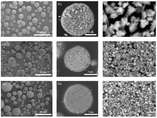
Figure 1.
Morphologies of LC feedstocks: Powder 1: (a) surface, (b) cross-sectional, (c) magnified cross-sectional; Powder 2: (d) surface, (e) cross-sectional, (f) magnified cross-sectional; Powder 3: (g) surface, (h) cross-sectional, (i) magnified cross-sectional.
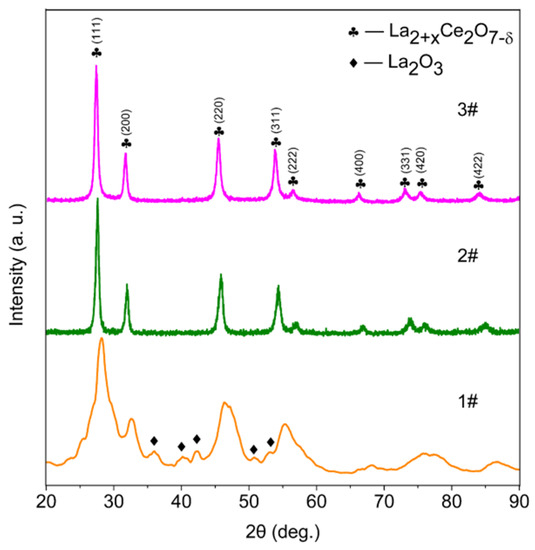
Figure 2.
XRD patterns of LC feedstocks.
3.2. Microstructure of LC Coatings
Microstructures of corresponding LC coatings deposited by the three feedstocks named as Coatings 1–3 are shown in Figure 3 and Figure 4. The coatings are all columnar structured from the top views. Many clusters are found on top of the columns in Coating 1 (Figure 3b), which is supposed to be solidification of tiny liquid droplets or condensation of vapors [31]. In contrast, the surface of the columns in Coating 2 is quite clean without clusters (Figure 3d). In Coating 3, clusters adhere on the column tops again (Figure 3f). From the cross-sectional microstructure, the bottom part of Coating 1 shows no obvious inter-columnar gaps (Figure 4a). Coatings 2 and 3 are well columnar structured from the bottom of the coatings (Figure 4b,c). However, Coating 2 has a deposition rate of 16.9 μm/min which is two times more than that of Coating 1. One reason must be the high powder feed rate of 9 g/min.
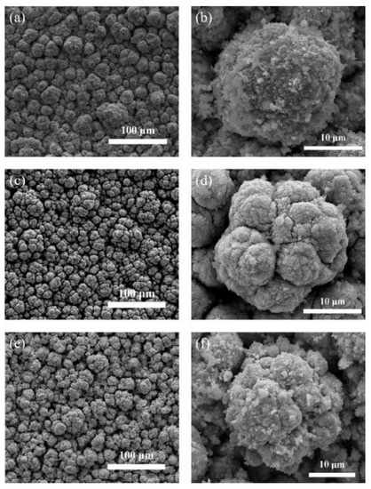
Figure 3.
Surface morphologies of corresponding LC coatings: (a) Coating 1, (b) Coating 1 (magnified); (c) Coating 2, (d) Coating 2 (magnified); (e) Coating 3, (f) Coating 3 (magnified).
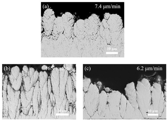
Figure 4.
Cross-sectional morphologies of corresponding LC coatings: (a) Coating 1, (b) Coating 2, (c) Coating 3.
Figure 5 shows magnified cross-sectional morphologies of different parts in the three coatings. At the bottom part of Coating 1 in Figure 5a, large amount of tiny splats with the size of less than 1 μm (marked with white dashed lines) can be observed. The tiny splats can cover the deposited coating and decrease the surface roughness at the early stage of coating deposition. It was investigated that shadowing effect is a factor responsible for column growth of PS-PVD coatings [32]. And shadowing effect is correlated to the angle between surface roughness and the direction of arriving deposits, hence column growth needs adequate surface roughness. With coating deposition proceeding, the tiny splats have less and less influence on the surface roughness due to the deposition of vapor phase. Accordingly, large column shape can form and inter-columnar gaps develop at the upper part of Coating 1 (Figure 4a). The internal structure of the developed large columns in Coating 1 displayed in Figure 5b is similar to that of the bottom part (Figure 5a). In Coating 2 many very fine particles can be seen and are marked with white dashed lines in Figure 5c. The unmelted primary particles are supposed to be a source of the very fine particles. In addition, supersaturation may occur in the boundary layer and therefore condensation of vapor phase might also be a source of the very fine particles [31,33,34]. Large number of defects exist in the internal structures of this column, which makes it look porous. Compared to Coating 2, fine particles are not found in Coating 3, which should be related to the high feedstock evaporation rate owing to the low powder feed rate and small primary particles.
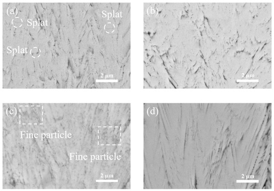
Figure 5.
Magnified cross-sectional morphologies of corresponding LC coatings: (a) Bottom part of Coating 1, (b) column internal part of Coating 1, (c) column internal part of Coating 2, (d) column internal part of Coating 3.
3.3. Composition of LC Coatings
The analyzed phase constituents of the coatings are depicted in Figure 6. Other than the main phase LC (FCC structure), a very small amount of La2O3 can also be identified in all the coatings. As there is hardly any La2O3 in Powders 2 and 3, the La2O3 in the Coatings 2 and 3 can only be formed during deposition. For Coating 1, another possibility is from the feedstock powder. The average La/Ce atomic ratios of LC feedstocks and corresponding coatings are listed in Table 4. The results of powders were measured by inductively coupled plasma-optical emission spectroscopy (ICP-OES), while the values of coatings were obtained by electron dispersive spectroscopy (EDS). To get convincible EDS results, 10 random positions were selected in each coating. At every position, average result of a large area on the coating surface was measured. According to the measured results, average values of powders are close to the nominal ones. Compared with the La/Ce atomic ratios in the powders, La losses are evident in the coatings. This phenomenon is related to much higher vapor pressure of CeO2, leading to higher content of Ce deposition in column-like coatings [35]. Additionally, more La lost in Coatings 2 and 3. Taking into consideration of coating morphologies, it may have correlations with higher feedstock evaporation rates. Contrary to vapor deposition, liquid deposition is supposed to reserve more La in the coatings [27].
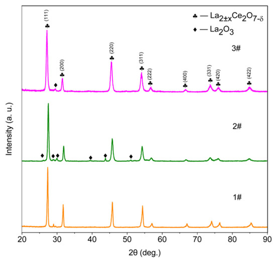
Figure 6.
XRD patterns of corresponding LC coatings.

Table 4.
Average La/Ce atomic ratios of LC feedstocks and corresponding coatings.
To further study the local phase compositions of the columns, an FIB specimen was prepared from the center of a column in Coating 3 as illustrated in Figure 7. As liquid droplets are supposed to be too thin to recognize in the cross-sectional view of TEM images [25], the FIB specimen was derived parallel to the surface direction. In Figure 7, gaps between sub-columns cannot be obviously observed, which may be related to different growth directions of sub-columns [25]. Due to the existence of solid particles, the original growth route of sub-columns can be changed. Moreover, round parts similar to the particles can be observed. However, sub-columns can also act like this from the top view. Therefore, only those sub-columns growing nearly parallel to the surface direction, thus looking to be in a rod-like shape, can be confirmed as vapor deposition. One of them was selected and shown in Figure 8a. As for liquid deposition, splashed shape is supposed to be the feature. As depicted in Figure 8b, the region was selected because the bottom edge has splashed tendency. According to the selected area electron diffraction (SAED) patterns, both the vapor and liquid deposition not only have FCC structures, but also super-lattice patterns. This indicates that it is pyrochlore LC phase [25,36,37,38]. The La/Ce atomic ratios of vapor and liquid deposition are 1.15 and 1.61, respectively.
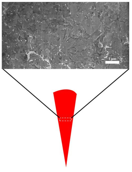
Figure 7.
Overview TEM image of the focused ion beam (FIB) specimen derived from Coating 3.
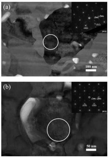
Figure 8.
TEM images and corresponding selected area electron diffraction (SAED) patterns: (a) vapor deposition, (b) liquid deposition.
3.4. Nano-Indentation Tests of LC Coatings
A comparison among the porosity inside the columns of LC coatings is depicted in Figure 9. It should be noted that the porosity only refers to the value at the middle region of columns rather than the entire coating. As illustrated in Figure 9, Coating 2 has the highest average value, which is in accordance with the porous morphology in Figure 5b. The deviation of the porosity in Coating 1 is the largest, which could be caused by non-uniform deposition of unmelted particles and liquid droplets as mentioned before.
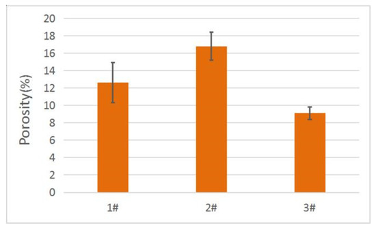
Figure 9.
Porosity inside the columns of LC coatings.
Figure 10 displays the hardness and Young’s modulus of the LC coatings. As illustrated, the lowest value of the average hardness belongs to Coating 2, while the highest one belonging to Coating 3 is approximately double of that. The Young’s modulus also presents a similar tendency. These results indicate that even though the effects of coating compositions cannot be totally excluded, both of the hardness and Young’s modulus have strong correlations with the porosity. For TBCs utilization, high hardness is necessary as it can enhance the erosion resistance [39], but very high Young’s modulus is unfavorable for reducing the strain tolerance [40]. Therefore, further investigations to control the porosity are still in need to optimize the hardness and Young’s modulus simultaneously.
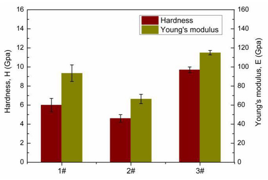
Figure 10.
Hardness and Young’s modulus of LC coatings.
4. Conclusions
LC coatings in possession of columnar structures were prepared by PS-PVD using three different feedstocks with same processing parameters. The correlations among powder characteristics, coating microstructures and compositions, as well as mechanical properties were also investigated. The main conclusions can be drawn as follows:
- (1)
- Small agglomerated feedstock, weak binding strength and small primary particle sizes can enhance the feedstock evaporation rates, thus obtaining well columnar structured coatings. Nevertheless, fine particles can be co-deposition inside the columns if the powder feed rate is too high.
- (2)
- The La/Ce atomic ratios of the coatings reduced compared to those of the feedstocks, especially the coatings with better columnar structure. Thus, to achieve stoichiometric LC coatings with well columnar structure, adding reasonable excess La in the feedstock is necessary.
- (3)
- Both the hardness and Young’s modulus of each coating show negative correlations with the porosity inside the columns. To optimize the hardness and Young’s modulus simultaneously for TBCs utilization, the porosity can be modified by adjusting the powder feed rate.
Author Contributions
All authors have read and agree to the published version of the manuscript. Conceptualization, C.Z.; methodology, C.Z. and L.W.; software, C.Z.; validation, C.Z., W.H., and H.G.; formal analysis, C.Z.; investigation, C.Z.; resources, H.G.; data curation, C.Z.; writing—original draft preparation, C.Z.; writing—review and editing, W.H. and H.G.; supervision, H.G.; project administration, J.H.; funding acquisition, H.G.
Funding
This research was funded by National Natural Science Foundations of China (NSFC), grant number 51590894 and 51425102; National Major Science and Technology Projects, grant number 2017-VI-0010-0081; the 111 Project, grant number B17002; Postdoctoral Science Foundation of China, grant number 2018M640040; China Scholarship Council (CSC).
Acknowledgments
The authors would like to express their thanks to Robert Vaßen and Georg Mauer for their insightful discussion and Yoo-Jung Sohn for her help with XRD analyses in IEK-1 of Juelich research center, Germany; to Jing He, Han Zou and Wen Ma for producing the LC feedstocks.
Conflicts of Interest
The authors declare no conflict of interest.
References
- Niessen, K.V.; Gindrat, M.; Refke, A. Vapor phase deposition using plasma spray-PVD. J. Therm. Spray Technol. 2010, 19, 502–509. [Google Scholar] [CrossRef]
- Hospach, A.; Mauer, G.; Vaßen, R.; Stöver, D. Columnar-structured thermal barrier coatings (TBCs) by thin film low-pressure plasma spraying (LPPS-TF). J. Therm. Spray Technol. 2011, 20, 116–120. [Google Scholar] [CrossRef]
- Rezanka, S.; Mauer, G.; Vaßen, R. Improved thermal cycling durability of thermal barrier coatings manufactured by PS-PVD. J. Therm. Spray Technol. 2014, 23, 182–189. [Google Scholar] [CrossRef]
- Gao, L.; Guo, H.; Wei, L.; Li, C.; Xu, H. Microstructure, thermal conductivity and thermal cycling behavior of thermal barrier coatings prepared by plasma spray physical vapor deposition. Surf. Coat. Technol. 2015, 276, 424–430. [Google Scholar] [CrossRef]
- Rezanka, S.; Mack, D.E.; Mauer, G.; Sebold, D.; Guillon, O.; Vaßen, R. Investigation of the resistance of open-column-structured PS-PVD TBCs to erosive and high-temperature corrosive attack. Surf. Coat. Technol. 2017, 324, 222–235. [Google Scholar] [CrossRef]
- He, W.; Mauer, G.; Sohn, Y.J.; Schwedt, A.; Guillon, O.; Vaßen, R. Investigation on growth mechanisms of columnar structured YSZ coatings in Plasma Spray-Physical Vapor Deposition (PS-PVD). J. Eur. Ceram. Soc. 2019, 39, 3129–3138. [Google Scholar] [CrossRef]
- Niessen, K.V.; Gindrat, M. Plasma spray-PVD: A new thermal spray process to deposit out of the vapor phase. J. Therm. Spray Technol. 2011, 20, 736–743. [Google Scholar] [CrossRef]
- Harder, B.J.; Zhu, D.; Schmitt, M.P.; Wolfe, D.E. Microstructural effects and properties of non-line-of-sight coating processing via plasma spray-physical vapor deposition. J. Therm. Spray Technol. 2017, 26, 1052–1061. [Google Scholar] [CrossRef]
- He, W.; Mauer, G.; Gindrat, M.; Wager, R.; Vaßen, R. Investigations on the nature of ceramic deposits in plasma spray-physical vapor deposition. J. Therm. Spray Technol. 2017, 26, 83–92. [Google Scholar] [CrossRef]
- Mauer, G.; Hospach, A.; Vaßen, R. Process development and coating characteristics of plasma spray-PVD. Surf. Coat. Technol. 2013, 220, 219–224. [Google Scholar] [CrossRef]
- Mauer, G.; Jarligo, M.O.; Rezanka, S.; Hospach, A.; Vaßen, R. Novel opportunities for thermal spray by PS-PVD. Surf. Coat. Technol. 2015, 268, 52–57. [Google Scholar] [CrossRef]
- Li, C.; Guo, H.; Gao, L.; Wei, L. Microstructures of yttria-stabilized zirconia coatings by plasma spray-physical vapor deposition. J. Therm. Spray Technol. 2015, 24, 534–541. [Google Scholar] [CrossRef]
- Zhang, B.; Wei, L.; Gao, L.; Guo, H.; Xu, H. Microstructural characterization of PS-PVD ceramic thermal barrier coatings with quasi-columnar structures. Surf. Coat. Technol. 2017, 311, 199–205. [Google Scholar] [CrossRef]
- Zhang, B.; Song, W.; Wei, L.; Xiu, Y.; Xu, H.; Dingwell, D.B.; Guo, H. Novel thermal barrier coatings repel and resist molten silicate deposits. Scr. Mater. 2019, 163, 71–76. [Google Scholar] [CrossRef]
- Thibblin, A.; Jonsson, S.; Olofsson, U. Influence of microstructure on thermal cycling lifetime and thermal insulation properties of yttria-stabilized zirconia thermal barrier coatings for diesel engine applications. Surf. Coat. Technol. 2018, 350, 1–11. [Google Scholar] [CrossRef]
- He, W.; Mauer, G.; Schwedt, A.; Guillon, O.; Vaßen, R. Advanced crystallographic study of the columnar growth of YZS coatings produced by PS-PVD. J. Eur. Ceram. Soc. 2018, 38, 2449–2453. [Google Scholar] [CrossRef]
- Yang, X.; Wei, L.; Li, J.; Zhang, B.; Wang, S.; Guo, H. Microstructural evolution of plasma spray physical vapor deposited thermal barrier coatings at 1150 °C studied by impedance spectroscopy. Ceram. Int. 2018, 44, 10797–10805. [Google Scholar] [CrossRef]
- Padture, N.P.; Gell, M.; Jordan, E.H. Thermal barrier coatings for gas-turbine engine applications. Science 2002, 296, 280–284. [Google Scholar] [CrossRef]
- Miller, R.A. Thermal barrier coatings for aircraft engines: History and directions. J. Therm. Spray Technol. 1997, 6, 35–42. [Google Scholar] [CrossRef]
- Nakanishi, N.; Shigematsu, T. Martensitic transformations in zirconia ceramics. Mater. Trans. JIM 1992, 33, 318–323. [Google Scholar] [CrossRef][Green Version]
- Basu, B.; Vleugels, J.; Van Der Biest, O. Transformation behaviour of tetragonal zirconia: Role of dopant content and distribution. Mater. Sci. Eng. A 2004, 366, 338–347. [Google Scholar] [CrossRef]
- Schulz, U.; Saruhan, B.; Fritscher, K.; Leyens, C. Review on advanced EB-PVD ceramic topcoats for TBC applications. Int. J. Appl. Ceram. Technol. 2004, 1, 302–315. [Google Scholar] [CrossRef]
- Cao, X.; Vaßen, R.; Fischer, W.; Tietz, F.; Jungen, W.; Stover, D. Lanthanum-Cerium Oxide as a thermal barrier-coating material for high-temperature applications. Adv. Mater. 2003, 15, 1438–1442. [Google Scholar] [CrossRef]
- Ma, W.; Gong, S.; Li, H.; Xu, H. Novel thermal barrier coatings based on La2Ce2O7/8YSZ double-ceramic-layer systems deposited by electron beam physical vapor deposition. Surf. Coat. Technol. 2008, 202, 2704–2708. [Google Scholar] [CrossRef]
- Zhao, C.; He, W.; Wei, L.; Guo, H. Microstructures of La2Ce2O7 coatings produced by plasma spray-physical vapor deposition. J. Eur. Ceram. Soc. 2019. [Google Scholar] [CrossRef]
- Jacobson, N.S. Thermodynamic Properties of Some Metal Oxide-Zirconia Systems; NASA Lewis Research Center: Cleveland, OH, USA, 1989. [Google Scholar]
- Wang, L.; Zhang, S.; Liu, T.; Li, C.; Li, C.; Yang, G. Dominant effect of particle size on the CeO2 preferential evaporation during plasma spraying of La2Ce2O7. J. Eur. Ceram. Soc. 2017, 37, 1577–1585. [Google Scholar] [CrossRef]
- Xu, Z.; He, L.; Zhao, Y.; Mu, R.; He, S.; Cao, X. Composition, structure evolution and cyclic oxidation behavior of La2(Zr0.7Ce0.3)2O7 EB-PVD TBCs. J. Alloy Compd. 2010, 491, 729–736. [Google Scholar] [CrossRef]
- Reed, R.C. The Superalloys: Fundamentals and Applications; Cambridge University Press: New York, NY, USA, 2006. [Google Scholar]
- Wang, L.; Zhong, X.; Zhao, Y.; Tao, S.; Zhang, W.; Wang, Y.; Sun, X. Design and optimization of coating structure for the thermal barrier coatings fabricated by atmospheric plasma spraying via finite element method. J. Asian Ceram. Soc. 2014, 2, 102–116. [Google Scholar] [CrossRef]
- Mauer, G.; Vaßen, R. Conditions for nucleation and growth in the substrate boundary layer at plasma spray-physical vapor deposition (PS-PVD). Surf. Coat. Technol. 2018. [Google Scholar] [CrossRef]
- Mauer, G.; Hospach, A.; Zotov, N.; Vaßen, R. Process conditions and microstructures of ceramic coatings by gas phase deposition based on plasma spraying. J. Therm. Spray Technol. 2013, 22, 83–89. [Google Scholar] [CrossRef]
- Liu, M.; Zhang, K.; Zhang, Q.; Zhang, M.; Yang, G.; Li, C.; Li, C. Thermodynamic conditions for cluster formation in supersaturated boundary layer during plasma spray-physical vapor deposition. Appl. Surf. Sci. 2019, 471, 950–959. [Google Scholar] [CrossRef]
- Girshick, S.L.; Chiu, C.P. Homogeneous nucleation of particles from the vapor phase in thermal plasma synthesis. Plasma Chem. Plasma Process. 1989, 9, 355–369. [Google Scholar] [CrossRef]
- Xu, Z.; He, S.; He, L.; Mu, R.; Huang, G.; Cao, X. Novel thermal barrier coatings based on La2(Zr0.7Ce0.3)2O7/8YSZ double-ceramic-layer systems deposited by electron beam physical vapor deposition. J. Alloy Compd. 2011, 509, 4273–4283. [Google Scholar] [CrossRef]
- Lian, J.; Wang, L.; Chen, J.; Sun, K.; Ewing, R.C.; Farmer, J.M.; Boatner, L.A. The order–disorder transition in ion-irradiated pyrochlore. Acta Mater. 2003, 51, 1493–1502. [Google Scholar] [CrossRef]
- Bae, J.S.; Choo, W.K.; Lee, C.H. The crystal structure of ionic conductor LaxCe1−xO2−x/2. J. Eur. Ceram. Soc. 2004, 24, 1291–1294. [Google Scholar]
- Andrievskaya, E.; Kornienko, O.; Sameljuk, A.; Sayir, A. Phase relation studies in the CeO2-La2O3 system at 1100–1500 °C. J. Eur. Ceram. Soc. 2011, 31, 1277–1283. [Google Scholar] [CrossRef]
- Gao, L.; Guo, H.; Wei, L.; Li, C.; Gong, S.; Xu, H. Microstructure and mechanical properties of yttria stabilized zirconia coatings prepared by plasma spray physical vapor deposition. Ceram. Int. 2015, 41, 8305–8311. [Google Scholar] [CrossRef]
- Bakan, E.; Mack, D.E.; Mauer, G.; Mücke, R.; Vaßen, R. Porosity-property relationships of plasma-sprayed Gd2Zr2O7/YSZ thermal barrier coatings. J. Am. Ceram. Soc. 2015, 98, 2647–2654. [Google Scholar] [CrossRef]
© 2020 by the authors. Licensee MDPI, Basel, Switzerland. This article is an open access article distributed under the terms and conditions of the Creative Commons Attribution (CC BY) license (http://creativecommons.org/licenses/by/4.0/).