1. Introduction
Silicon carbide fiber-based ceramic matrix composites (CMCs) offer a high potential for applications as structural components in advanced gas turbines. In comparison to metallic super alloys, used in the state of the art, the main advantages of these materials were found to be their low specific weight in combination with a superior potential at elevated temperatures up to 1400 °C. Furthermore, among ceramic materials, CMCs are characterized by a damage-tolerant fracture behavior, suggesting them as promising candidates for gas turbine applications as well. During recent years, significant progress has been achieved in material development and processing. However, there are still considerable deficits at present, especially in the long-term behavior of the composites in hot gas atmosphere. Corrosion processes were observed, caused by the high water vapor pressure in combination with high temperatures and gas velocities. The resulting microstructural and mechanical degradation of the composites and the damage mechanisms of these processes have been described in several studies [
1,
2,
3,
4,
5,
6]. Volatilization of the protective silica-based surface layer by the formation and evaporation of silicon hydroxides (Si(OH)
4) was found to be the main process leading to considerable material loss with recession rates in the range of 1 μm/h (Equation (1)). Additional material degradation as a consequence of oxidation processes inside the composite was observed.
Environmental barrier coatings (EBCs) have been the solution to prevent the surface corrosion of the ceramic materials in gas turbine atmospheres [
7,
8]. During the last few years, different EBC systems have been introduced [
8,
9,
10]. As a consequence of the complex conditions during operation at elevated temperatures in a hot gas atmosphere, multilayer coatings with special functions were proposed. In this way, several features required to guarantee the long-term stability of the EBC system in hot gas conditions could be realized.
Beside their stability against erosion, interaction with Ca-Mg-Al-silicates (CMAS), or foreign object damage, the top layer of the system must primarily exhibit a superior water vapor corrosion stability. During recent years, several oxide systems with superior corrosion stability have been suggested to protect non-oxide ceramics or CMCs based on Si
3N
4 or SiC against water vapor corrosion [
11,
12]. Among these oxide systems, rare-earth (RE) silicates have been identified as promising EBC candidates for top layer materials. While the RE-monosilicates are mostly stable in a hot gas environment, the disilicates were found to be partially volatilized with the formation of silicon hydroxide and the more stable monosilicate (Equation (2)) [
8,
12,
13,
14,
15,
16,
17].
This corrosion process led consequently to the formation of a stable monosilicate layer, influencing the corrosion behavior of the EBC system during long-term application.
Currently, a layer based on metallic silicon is used as a very effective bond coat in several EBC systems [
18,
19]. With a melting point of about 1410 °C, silicon bond coats are limited in their temperature potential. For use at lower temperatures, however, they are characterized by several benefits. First, the coatings agree well with the coefficient of thermal expansion (CTE) of the non-oxide CMC substrate material. The second point is the getter function of the silicon against the permeation of oxidizing compounds (O
2, H
2O) and prevention of oxidation processes inside the CMC component.
Various multilayer EBC systems with Si bond coats and RE-top coats were demonstrated to be quite effective in the protection of SiC
F/SiC CMC [
10,
16,
17,
20,
21]. However, during operation at elevated temperatures in hot gas atmosphere, several processes led to degradation of the whole system. A summary of possible failure modes was reported by Lee [
19]. Processes like the formation of stresses during thermal cycling, foreign objects, phase transformation, or sintering processes resulted in cracking, delamination, and spallation of the EBC system. Additional chemical processes like water vapor or CMAS corrosion limit the stability and functionality of the protecting system. During long-term use, oxidation processes were found to be an additional critical factor for the stability of the EBC. Diffusion of oxygen and, especially, the permeation of H
2O through the different EBC layers are responsible for the formation of a thermally grown oxide (TGO) layer of mainly silica at the upper side of the Si bond coat. With growing thickness of the SiO
2 TGO layer, crystallization and phase transition processes (cristobalite) were observed, finally leading to stresses in the EBC system with the consequence of cracking and spallation of the EBC [
10,
16,
22].
In real conditions, the formation of the TGO layer cannot be avoided. There will always be permeation of oxygen and water into the material, finally leading to oxidation processes inside. However, there are strategies to minimize the rate of TGO layer formation and their following influences. First, the transport of the oxidants (O
2 and H
2O) through the EBC system should be considered. There is still a considerable lack of data about the permeation properties (diffusion coefficient, oxidant solubility) of the various materials used in the EBC layer system. Furthermore, the morphology of the different layers, like layer thickness, porosity, crystallinity, and grain boundary structure, has to be studied regarding their influence on their permeation properties. Recently, an example in this direction was introduced by Lee [
19]. The TGO growth rate in an EBC system with the Si bond coat and Yb
2Si
2O
7 was found to be significantly reduced by modifying the Yb
2Si
2O
7 layer with various oxides (Al
2O
3, mullite, Y
3Al
5O
12). As a conclusion of these results, he suggested a modification of the SiO
2 network structure of the TGO by incorporating Al
3+- and Yb
3+-ions, consequently leading to lower permeation rates of oxidants (H
2O) through the TGO layer.
A defined control of the oxidation and corrosion processes itself was found to be a second strategy. This can be performed by modification of the oxidation mechanism, e.g., defined reaction products or the location where the oxidation takes place. An example for such a strategy was reported for monolithic Si
3N
4 with SiC or MoSi
2 additions [
12,
23]. During oxidation of these composites, a changed oxidation mechanism with the formation of Si
2ON
2 in the top region of the bulk material was observed, leading finally to less defect formation caused by the oxidation processes in the microstructure of the material. The focus of this study was placed in a similar direction, namely, to avoid the formation of a TGO as a reaction layer at, e.g., the silicon bond coat, by a defined reaction of the permeating oxidants at other regions.
2. Materials and Methods
The base CMC material was fabricated by winding technology with polycrystalline SiC fibers, Tyranno SA3 (UBE Industries, Tokyo, Japan). Prior to winding, the desized SiC tows were infiltrated with an aqueous slurry composed of SiC powder, Sintec 15 (Saint Gobain, Courbevoie, France), and 20 vol.% sintering additives with Al
2O
3, AKP 50 (Sumitomo Chemical, Tokyo, Japan); Y
2O
3, Grade C (H.C. Stark, Goslar, Germany); and SiO
2, Aerosil Ox 50 (Evonic Industries, Essen, Germany). The wound cylinder (85° winding angle) was cut and pressed, opening into a flat sheet. Matrix formation was performed in five steps of precursor infiltration and pyrolysis (PIP) with commercially available polysilazane Si-C-N precursor, HTT 1800 (Clariant Advanced Materials GmbH, Muttenz, Switzerland). Afterward, the composite was sintered at 1400 °C in nitrogen atmosphere. Finally, a SiC
F/SiC(N) composite with a fiber volume content between 40% and 50% and an open porosity of about 10% was obtained. Further details about the CMC fabrication are described in [
24]. Bars with dimensions of 3 × 10 × 36 mm³ were used as test samples.
The first EBC system was a bond coat from Al
2O
3 with a top coat of yttrium aluminum garnet (Y
3Al
5O
12, YAG). Both layers were fabricated by atmospheric plasma spraying. The second system was a three-layer coating system with a Si bond coat, an intermediate layer consisting of a mixture of Yb
2Si
2O
7/SiC and Yb
2SiO
5 as the top coat. While the Si bond coat was fabricated by atmospheric plasma spraying (APS), the two rare-earth-containing layers were fabricated by suspension plasma spraying (SPPS). An overview of the coatings fabricated is given in
Table 1:
Both EBC systems were tested regarding their oxidation resistance at 1200 °C for 100 h in furnace air. Additionally, hot gas corrosion tests were conducted in a high-temperature burner rig at atmospheric pressure [
11]. The coated test samples were blown directly by the hot gas in a reactor tube of solid-state sintered SiC with an inner diameter of 30 mm. The hot gas was composed of the combustion products of natural gas in air and additional water vapor. The conditions of the corrosion tests are summarized in
Table 2. Further details regarding the burner rig test are described in [
11].
After both tests, the microstructure of the samples was characterized by means of polished cross-sections with field-emission scanning electron microscopy (Ultra 55, Zeiss, Oberkochen, Germany). Information about the composition of the different layers after oxidation and corrosion was obtained by using energy-dispersive X-ray spectroscopy (EDX; ISIS Si (Li) detector).
3. Results
A summary of the weight changes of the two coating systems in comparison to the base CMC substrate without coating observed during oxidation and the burner rig test is summarized in
Table 3. A weight gain was observed for all materials investigated after both tests.
The values are the average of the three samples each. In connection with the interpretation of these results, some inaccuracies as a consequence of inhomogeneous EBC layers (thickness, pores, or cracks) should be considered. Furthermore, during the burner rig test, both processes, weight gain and weight loss, were observed. These results cannot be correlated directly with the TGO scale thickness obtained after the tests; however, some general tendencies can be followed as described in the microstructural discussion of the material investigated.
The main results were obtained by comparison of the microstructure of the CMC with different EBCs after oxidation and hot gas corrosion tests both at 1200 °C and 100 h. After oxidation, a weight gain was observed. During the test, oxygen diffused through the EBC layer and finally reacted at the first non-oxide surface in the system (base SiCF-SiC(N) composite or Si bond coat). Usually, a TGO layer was formed. In the case of the hot gas corrosion test, a second reaction has to be considered as well. Water vapor penetrated through the EBC layer, reacted with the SiO2 of the TGO layer, and formed volatile Si(OH)4. As a consequence of the high gas speed, the equilibrium of the corrosion reaction in Equation (1) was strongly shifted to the formation of Si(OH)4. In this way, the water vapor corrosion of the TGO became more dominant, resulting in material loss and a gap formation between the silica TGO and the EBC top layer.
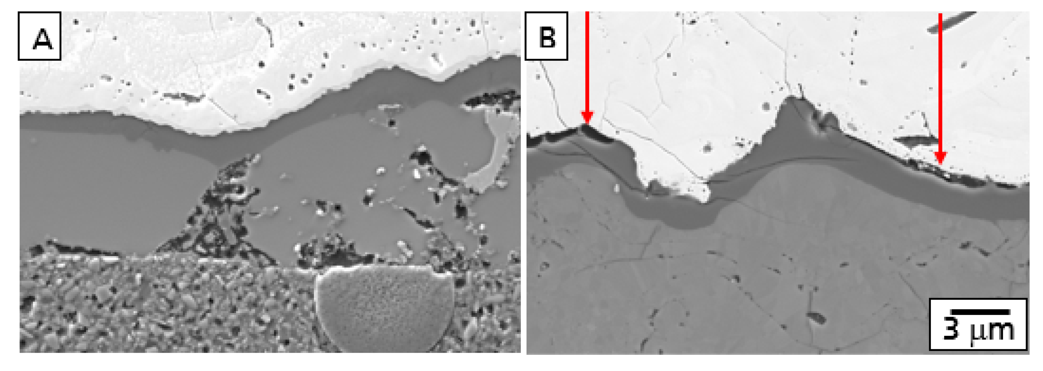
This behavior is described in
Figure 1 showing the comparison of polished cross-sections of the microstructure after oxidation and corrosion of a model EBC system consisting of a Si bond coat and an Yb
2SiO
5 top coat. While a TGO was formed (A) after oxidation, corrosion processes with the formation of gaps at the Yb
2SiO
5-Si interface (B) were observed.
3.1. CMC Substrate Material
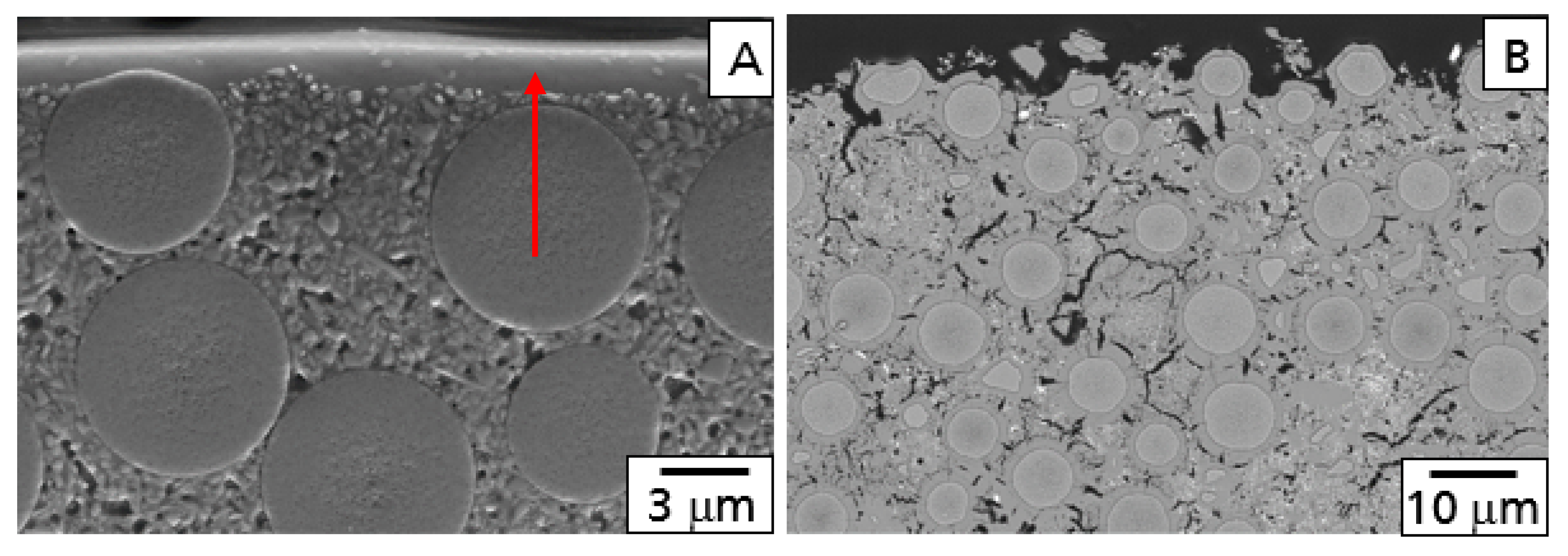
The results of the high-temperature tests of the base CMC without EBC were characterized by investigation of the microstructure of the surface region. After both tests, oxidation and the burner rig, a weight gain was observed. During oxidation, a protective layer of mainly SiO
2 was formed at the surface of the material, limiting the diffusion of oxygen into the material (
Figure 2A). This behavior was comparable to dense monolithic SiC. Both oxidation (weight gain) and corrosion (weight loss) were observed during the burner rig test. Caused by the water vapor corrosion of the protecting SiO
2 surface layer, oxygen and water vapor were able to diffuse deeper into the material and oxidized the matrix and the fibers too (
Figure 2B). As a consequence of these oxidation processes inside of the material, a higher weight gain was found after the burner rig test.
3.2. Al2O3–YAG EBC Coating System
In the case of the material coated with Al
2O
3-YAG, a weight gain was observed after both tests. The values were found to be higher in comparison to the base CMC. Two effects are assumed to be the reason; first, a low protective ability caused by the inhomogeneity of the double layer with a high amount of cracks and porosity, and second, the TGO as the rate controlling factor for oxidation based on an alumosilicate glass with a significantly higher diffusion ability in comparison to the surface oxidation layer formed during oxidation of the base CMC [
25].
The microstructure of the Al
2O
3-YAG EBC coating on the SiC
F-SiC(N) composite in the coated condition is illustrated in
Figure 3.
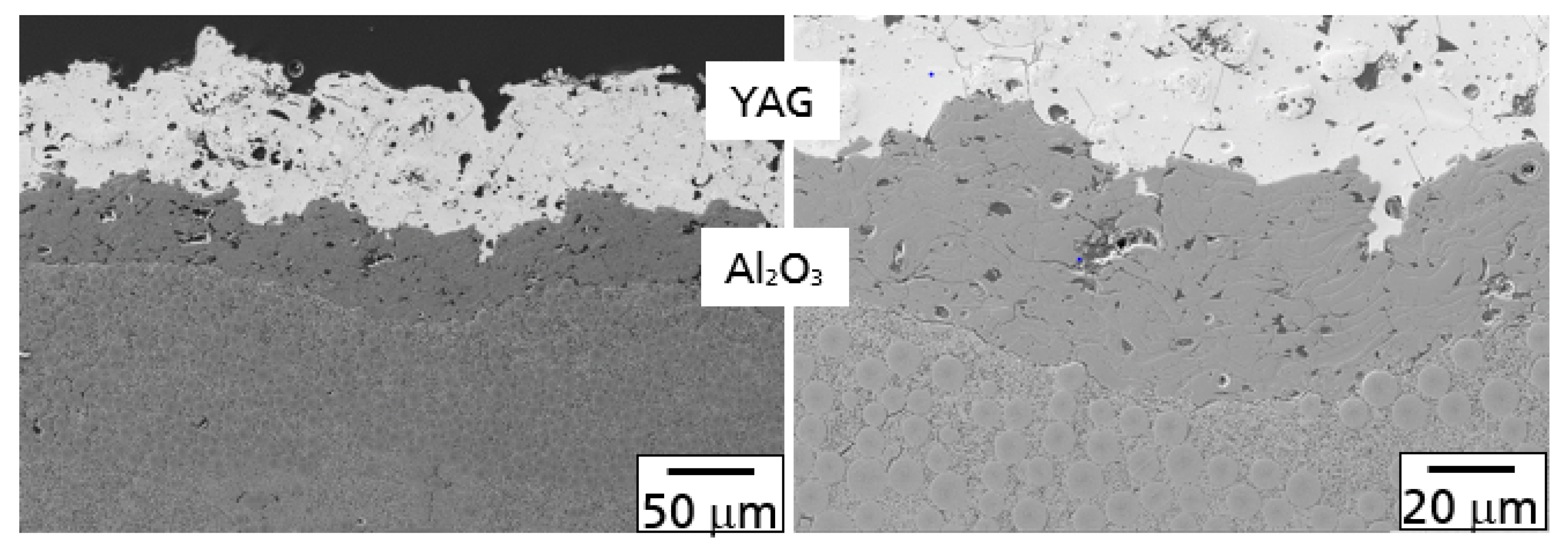
In principle, both processes, as described above, were observed after oxidation and the hot gas test. A comparison of polished cross-sections with the Al
2O
3/YAG coating is shown in
Figure 4 after oxidation in air (A) and the burner rig test (B) at 1200 °C and 100 h.
During the oxidation test, oxygen diffused through the YAG/Al
2O
3 layer and oxidized the SiC fibers and SiC(N)-matrix to SiO
2. Consequently, a TGO layer at the interface of the CMC base material and the Al
2O
3 bond coat was formed. Furthermore, a part of the oxidation product was found in the grain boundaries and triple junctions of the Al
2O
3 bond coat. The composition of the oxidation products in both the TGO and Al
2O
3 layer was a glassy alumosilicate (
Figure 4A).
As described above, corrosion processes were observed additionally after the burner rig test (
Figure 4B). The alumosilicate glass in both the TGO and the grain boundaries and triple junctions were found to be corroded, forming small pores and voids in the Al
2O
3 bond coat and gaps between the top of the TGO and the bond coat. With increasing time, both corrosion processes will damage the EBC system. Especially, the corrosion of the TGO will form large defects, finally leading to failure of the EBC. The smaller pores and voids in the alumina bond coat, however, are much more stable from a mechanical point of view.
Notwithstanding other damage mechanisms, this behavior opens an idea to the enhance high-temperature stability of the EBC in principle. By the shifting of the oxidation processes from the interface of the TGO into the volume of the bond coat, it should be possible to decelerate the TGO formation. Furthermore, the damage mechanism in the TGO (crystallization processes and corrosion) could be avoided, and only smaller corrosion defects in the bond coat should be observed.
3.3. Si–Yb2Si2O7/SiC–Yb2SiO5 EBC Coating System
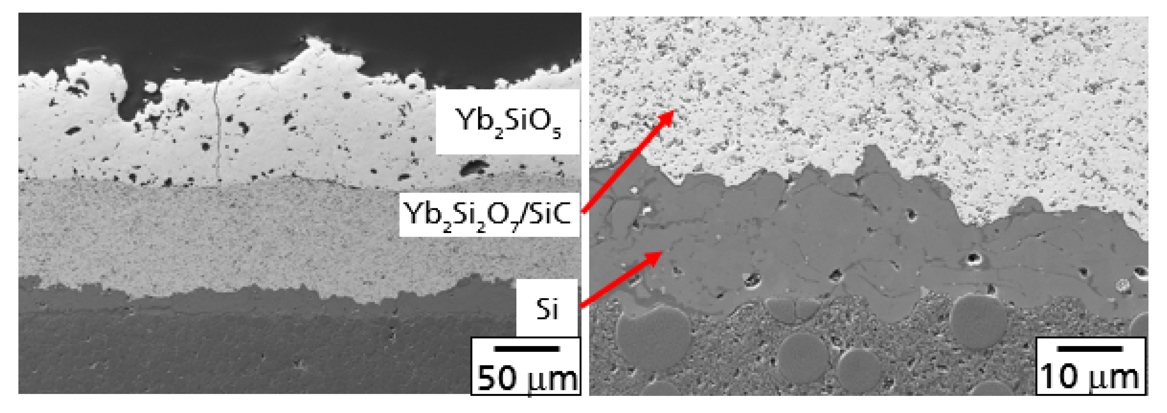
This mechanism described above was considered in the design of a three-layer coating system investigated next with a silicon bond coat, an intermediate layer consisting of Yb
2Si
2O
7 with SiC particles, and Yb
2SiO
5 as the top coat featured by a superior hot gas stability. The microstructure of this EBC is demonstrated in
Figure 5. Few microcracks were observed in the Yb
2SiO
5 top layer, probably as a consequence of the CTE mismatch between the top and intermediate layer (CTE Yb
2Si
2O
7 4.2 × 10
−6 K
−1; CTE Yb
2SiO
5 6.8 × 10
−6 K
−1).
In comparison to the other materials investigated, only a small weight gain was measured after both tests at elevated temperatures. This should be caused by a protecting function, especially of the Yb
2Si
2O
7/SiC layer. Oxygen diffusion through the EBC layers and the oxidation reaction in the Yb
2Si
2O
7/SiC layer were found to be the main processes observed after the oxidation test. The SiC particles in the intermediate layer were oxidized, consequently leading to the formation of a SiO
2 scale on the SiC particles. The diffusion of oxygen through this SiO
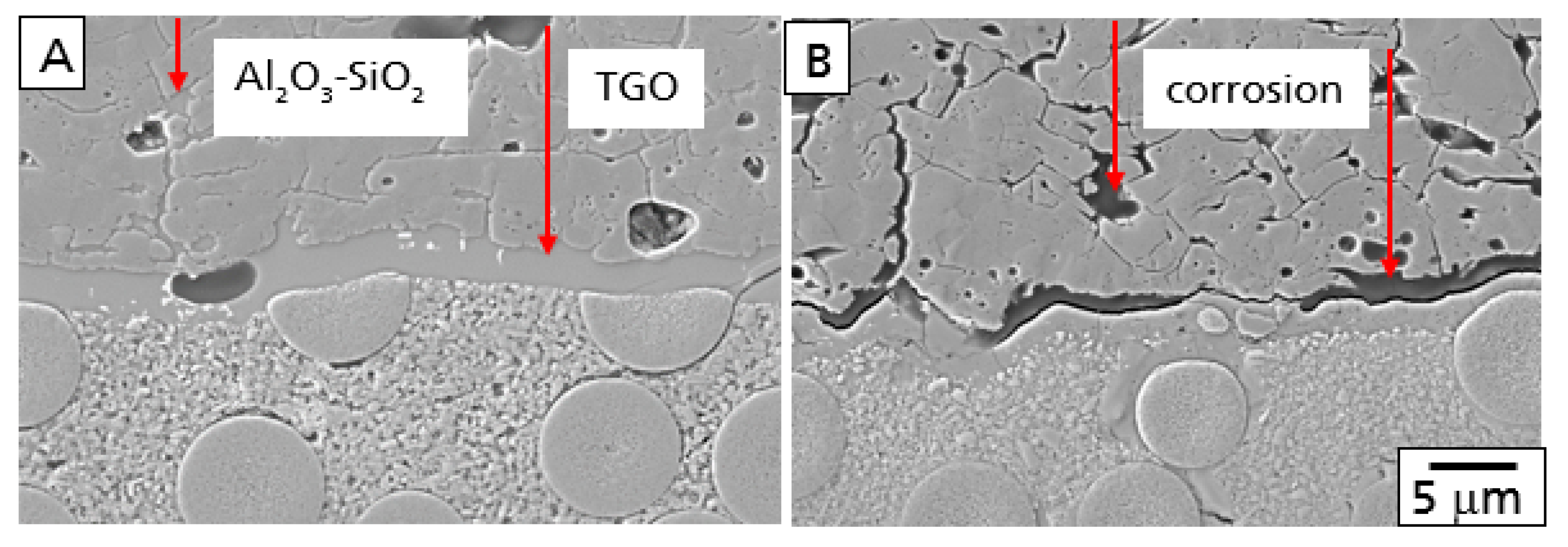
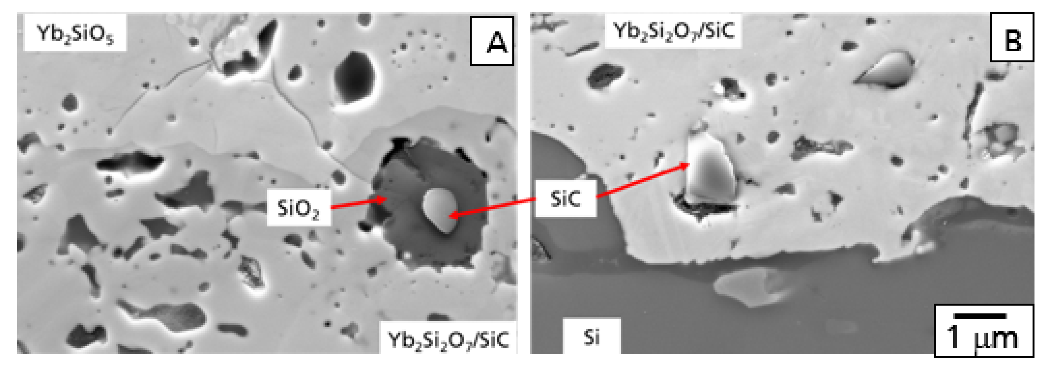
2-based layer controlled the oxidation process of the whole system during the testing time performed. A typical example for the mechanism is demonstrated in
Figure 6A, presenting a polished cross-section at the interface of the Yb
2SiO
5 top coat and the Yb
2Si
2O
7/SiC intermediate layer.
The SiC particles in this layer operated as a getter for the diffusion of oxygen, preventing further oxygen at diffusing deeper into the material. This effect is illustrated in
Figure 6B with the microstructure at the interface between the Si bond coat and the Yb
2Si
2O
7/SiC intermediate layer. As the diffusion of oxygen reacted with SiC particles in the upper region of this layer, no oxidation processes were observed in this area. The SiC grains did not show an oxidation layer. Furthermore, the formation of a TGO was not observed. Similar results on the graded oxidation of SiC-particles have been reported in context of the mechanical self-healing ability of Yb
2Si
2O
7/SiC composites [
26,
27].
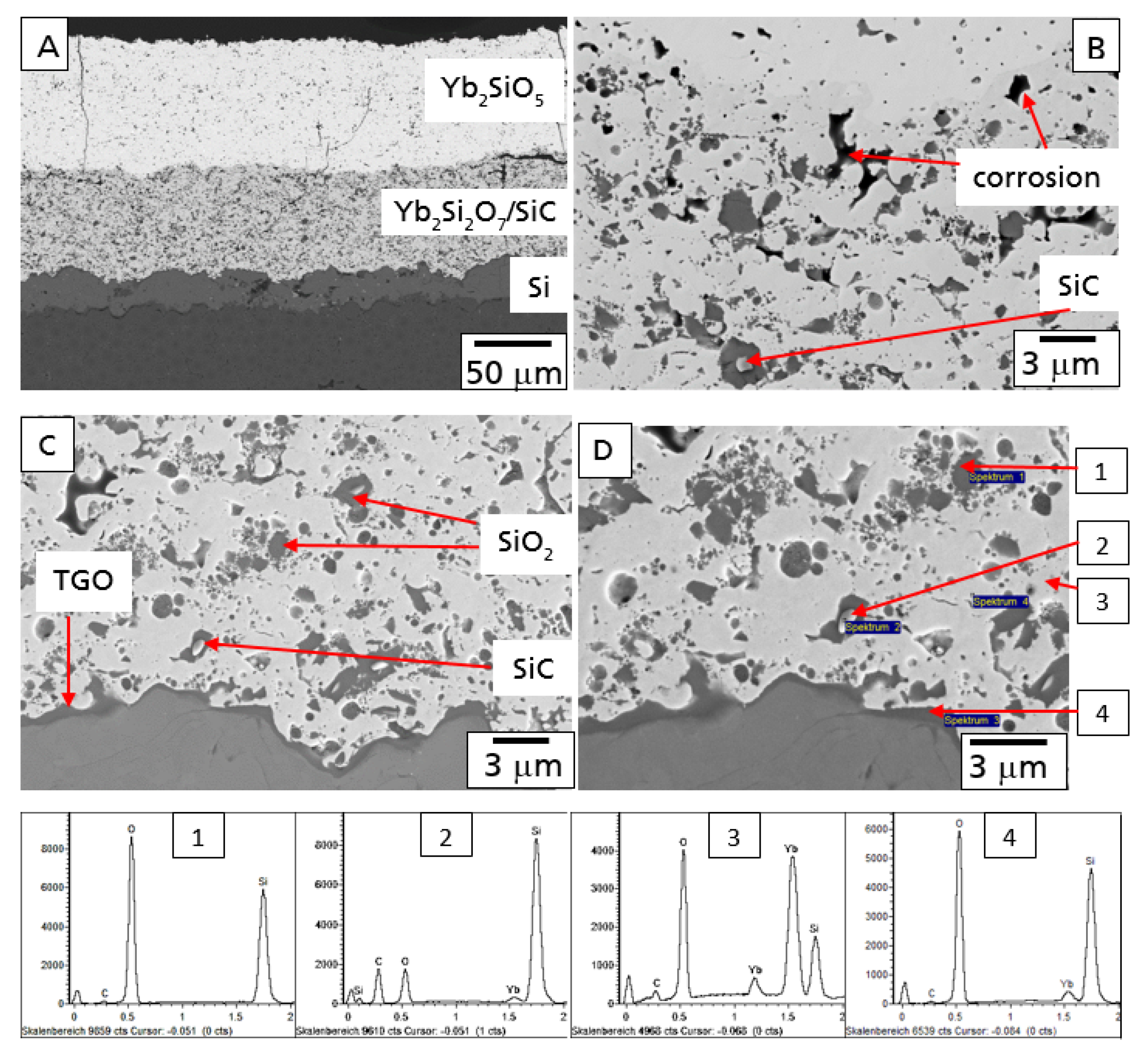
In
Figure 7, the microstructure of this EBC system is shown after the 100 h hot gas corrosion test at 1200 °C. Although some additional cracks formed, the EBC coating is still intact, protecting the CMC from the direct hot gas corrosion attack (
Figure 7A).
In comparison to the oxidation test, stronger oxidation processes were observed in the Yb
2Si
2O
7/SiC layer after the test in hot gas conditions. A higher amount of oxidants reached and oxidized the SiC particles in the intermediate layer of the EBC coating system as a consequence of additional water vapor permeation. In agreement to the literature [
28,
29], water vapor was found to be the dominant oxidant caused by the significantly higher solubility of H
2O in SiO
2. A second reasonable possibility is the formation of interconnected open splat boundaries in the Yb-silicate layer [
26]. Further investigation has to be performed in this field. The SiC particles were found to be oxidized to SiO
2 up to the bottom of the Yb
2Si
2O
7/SiC layer. As a part of the oxidant reached the Si-bond coat the TGO layer started to grow (
Figure 7C). Results of EDX analysis of microstructural details of this part are presented in
Figure 7.
Additional processes were observed in the top region of the Yb
2Si
2O
7/SiC layer. Some of the SiO
2 areas formed by the oxidation of the SiC particles were found to be corroded by water vapor, finally leading to the formation of pores in the top region of the intermediate layer (
Figure 7B).
4. Discussion
As already mentioned above, the penetration of oxidants into the EBC system and the following formation of a TGO cannot be prevented completely. However, with purposeful design of the EBC layer system, the transport processes and the following oxidation processes can be influenced. The first possibility should be the reduction of the transport processes for O2 and H2O. Coatings with a lower oxygen diffusion coefficient and water vapor solubility are reasonable trends for material development.
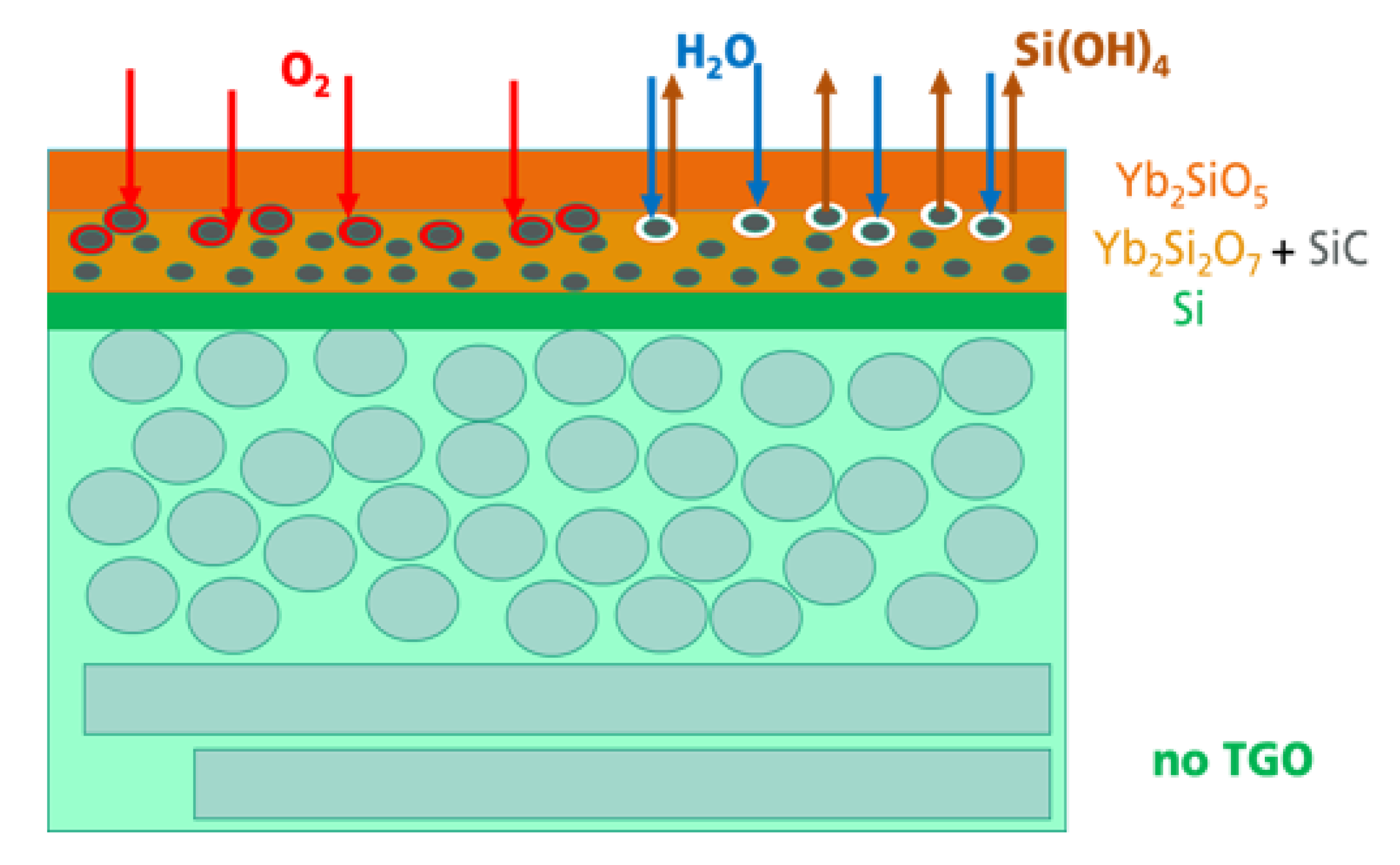
In the present study, the following oxidation and corrosion processes were modified. With the introduction of oxidable particles into an intermediate layer, it was possible to shift the oxidation processes from the interface between the Si bond coat and the Yb-silicate top coat to a volume in the intermediate layer. The processes occurring during oxidation and corrosion are schematically described in
Figure 8.
Independent of the thermal treatment, oxidation, or hot gas corrosion, the transport of oxidants and the following oxidation processes in the EBC system were found to be the first processes in the system. The penetrated O2 and H2O reacted with the SiC, resulting in the formation of a SiO2-based shell surrounding the SiC particles. In this way, the SiC particles served as a getter for the further transport of oxidants into deeper regions of the whole system. As the oxidants could not reach the Si bond coat, the formation of the TGO was prevented. In a hot gas atmosphere with increased water vapor pressure and high gas velocity, corrosion processes were observed. The water vapor penetrated this region and reacted with the SiO2 at the surface of the SiC particles and formed Si(OH)4. A Si(OH)4 gradient developed as a consequence of the high hot gas velocity outside, which was a driving force of the outward transport and evaporation of the Si(OH)4. Small pores were found to be the result of the corrosion process.
The beneficial gettering function of the SiC particulate will be a temporary effect only. After longer oxidation time or at higher temperatures, the SiC particles will be consumed and oxygen will reach the silicon bond coat to form the TGO. However, with the incorporation of the SiC particles, to be oxidized during operation in hot gas atmosphere, the EBC system could be temporary stabilized. With the delayed formation of the TGO, their resulting damage mechanisms, cracking as a result of stresses by crystallization and phase transition processes and the gap formation caused by corrosion material loss, started at later application times. A very beneficial effect in terms of long-term stability and lifetime can only be achieved by simultaneous improvement of the oxygen and H2O permeation behavior of the whole EBC layer system. The lower the transport of the oxidants into the material, the longer the gettering function of the SiC particles can be used. Further studies have to be performed to optimize the EBC system regarding composition and microstructure with special focus on the transport mechanisms during service in hot gas environments.
