Article

The Problem of Copper Softening During Cold Gas Dynamic Spraying

1
Laboratory of Electric Currents Assisted Sintering Technologies, Moscow State University of Technology “STANKIN”, Vadkovsky lane 3a, 127055 Moscow, Russia
2
Department of Scientific Research Programs, Grants and Projects, Railway Research Institute JSC “VNIIZHT”, 3rd Mytischinskaya Street 10, 107996 Moscow, Russia
*
Author to whom correspondence should be addressed.
Coatings 2020, 10(1), 7; https://doi.org/10.3390/coatings10010007
Submission received: 20 November 2019 / Revised: 16 December 2019 / Accepted: 17 December 2019 / Published: 20 December 2019
(This article belongs to the Section Surface Characterization, Deposition and Modification)

Abstract

:
The effect of the gas-dynamic (cold) spraying of the Cu-Al2O3-Zn powder mixture on the microstructure and strength of the copper substrate is investigated. A copper cold drawn contact wire was used as a substrate. We propose using gas-dynamic cold spraying to restore the local wear of the contact wire. The study of the microstructure using the electron backscattered diffraction (EBSD) method showed the presence of grain orientation characteristics of the cold drawing of copper. Recrystallization of the surface layers of the contact wire during spraying does not occur. Using the microhardness measurement, the absence of softening of the layers of the contact wire with a depth of up to 2 mm is shown. The results of mechanical tests show that spraying does not lead to a decrease in the tensile strength of the contact wire. The results of creep tests show that spraying does not lead to a decrease in the heat resistance of the contact wire.

1. Introduction

The contact wire of an electrified railway is manufactured by means of cold drawing with the reduction ratio of approximately 60%. According to IEC 62917:2016, tensile strength of a contact wire with a cross-section of 120 mm2, is at least 360 MPa (breaking load is 41.9 kN). The copper contact wire is operated under the following conditions. Tensile stress of the copper contact wire varies from 100 to 120 MPa during operation. Operation temperature of the contact wire is approximately 100 °C. Therefore, the wire strength plays an important role during its operation. It must not decrease in the process of operation and repairing, including the restoration of local wear of a contact wire.
Increased wear of the contact wire during operation occurs in locations where its displacement is limited. This type of contact wire wear is called local wear. The local wear limit is achieved several times faster than that which is achieved over the rest of the length of the contact wire. The length of the local wear section is up to 0.5 m. There are 1 or 2 of these worn sections on single contact wire (length about 1.5 km). In worn sections, the contact wire loses up to 20% of the cross-sectional area. Accordingly, the contact wire loses up to 20% of the breaking load in worn areas. Therefore, the main requirement for the technology for restoring local wear is that the contact wire does not reduce strength, and that the layers of the contact wire adjacent to the spraying area do not recrystallize. Due to the local wear with a length of up to 0.5 m, a contact wire that is 1.5 km long is replaced with a new contact wire, especially on high-speed railways [1,2,3,4,5,6,7]. To repair the local wear of contact wires, it is necessary to apply a layer with a thickness of approximately 2 mm and a width of approximately 10 mm on the strained Cu contact wire at a length of approximately 500 mm. The application time of a layer must not exceed 1 h. The limiting requirement for the contact wire recovery technology is the absence of softening of the contact wire and recrystallization of its surface layers after spraying. Repairing of the local wear should not result in a decrease of tensile strength below 360 MPa for a contact wire with the cross-section of 120 mm2.
As a result, the technology of gas dynamic (cold) spraying was proposed in [8] for in situ repair of local wear in contact wires. A vast number of research works, for example, have been devoted to application and study of the gas dynamic (cold) spraying technology [9,10,11,12,13,14,15,16,17,18,19,20,21,22]. The research works cover numerous theoretic and experimental problems associated with gas dynamic cold spraying. There are a significant number of studies on the deposition of copper particles, for example [23,24,25,26]. Many research works are associated with spraying on steel, titanium and aluminum and other metallic substrates. There is a lack of work associated with spraying on a copper substrate, in particular, on copper contact wires. Basically, the research works are devoted to the structure of a sprayed layer, calculation of temperature fields, calculation of velocities of particles sprayed and mechanics of the interactions. The papers devoted to the gas dynamic (cold) spraying method do not pay sufficient attention to the impact of the spraying process on possible changes in substrate structure and properties. When choosing a technology for restoring local wear of contact wires, the effect of the deposition process on the properties of the contact wire (substrate) is decisive. The process of restoring local wear (cold gas-dynamic spraying) should not lead to a loss of contact wire strength. The temperature of the air, which is a carrier gas, vary from 400 to 500 °C. The temperature ensures the maximum strength of the layer/substrate adhesion. The temperature of copper recrystallization commencement is 150–250 °C, depending on the copper purity [27]. The temperature of the stream that processes the contact wire is higher than the temperature of copper recrystallization. Therefore, there is the possibility of recrystallization and a decrease in the tensile strength of the contact wire.
Overheating of the contact wires is the main reason for their breakage in operation. Overheating leads to partial or complete recrystallization of the contact wire section. Recrystallization leads to a decrease in the tensile strength of the contact wire. Under the action of operational tensile load and temperature, the recrystallized section of the contact wire quickly breaks due to creep.
Recrystallization during gas-dynamic spraying was considered from the point of view of the formation of a metallurgical bond of particles with the substrate [28,29,30,31,32]. In this case, the recrystallization of the sprayed particles and not the substrate was studied. Consequently, this paper investigates the impact of gas dynamic (cold) spraying, with the purpose of restoration the worn contact wire, on the contact wire strength and recrystallization of the copper subsurface layers.

2. Materials and Methods

The following materials were used for this research work. The Cu-OF copper contact wire with the cross-section of 120 mm2 (IEC 62917 ‘Railway applications—Fixed installations—Electric traction—Copper and copper alloy grooved contact wires’) was used as the substrate. Hardness of the contact wire was 115–125 HB. For deposition, the Cu-50% Al2O3 (corundum), Cu-60% Al2O3, Cu-50% Al2O3-5% Zn, Cu-50% Al2O3-10% Zn powder mixtures were used. The powder mixture was applied to the substrate in an air stream. The flow rate was about 90% of the speed of sound. The air temperature in the stream was 500 °C. The duration of interaction of the heated stream with the contact wire was: for the mixture Cu-50% Al2O3—10 min, for the mixture Cu-60% Al2O3—13 min, for the mixture Cu-50% Al2O3-5% Zn—6 min, for the mixture Cu-50% Al2O3-10% Zn—4 min. The average particle size of the powders of Cu and Zn is 60 microns. The average particle size of the powder Al2O3 (corundum) is 40 microns. Purity of powder materials is 99.5%. Powders were made by Joint-Stock Company DIMET, Obninsk city Kaluga region, Russia.
The samples of the repaired contact wire were cut transversely to and along the axis of the wire into wafers by means of electro-sparking, then grinded and subjected to mechanical and electrochemical polishing for examinations using optical and electron microscopes.
Typical sample image is shown in Figure 1. The orange area is the copper wire body, and it is apparent that the wire top is flat, i.e., the wire was worn.
Studies of a possible recrystallization of surface layers of the substrate (contact wire) were carried out using the optical microscope (Neophot 21, Carl Zeiss, Jena, Germany) and scanning electron microscope (SEM, Vega-3, Tescan, Brno, Czech Republic) by means of electron backscattered diffraction (EBSD) to determine the grain misorientation and investigate the texture. As a result of the EBSD analysis, the orientation distribution patterns for each grain over the targeted sample surface area as well as the associated direct and inverse pole figures were obtained.
The direct pole figures demonstrate the orientation of the certain plane family (for example, (100), (111)) with reference to a chosen external plane (for example, the scanning plane or rolling plane).
The inverse pole figures (IPFs), on the contrary, show the orientation of the certain directions (for example, direction of the normal to the scanning plane) with reference to the local crystallographic coordinate systems of the crystallites. The method EBSD was used to study the recrystallization of particles of a deposited material after gas-dynamic (cold) spraying [32,33], but not the substrate. Recrystallization of the surface layers of the substrate can lead to a partial softening of the contact wire.
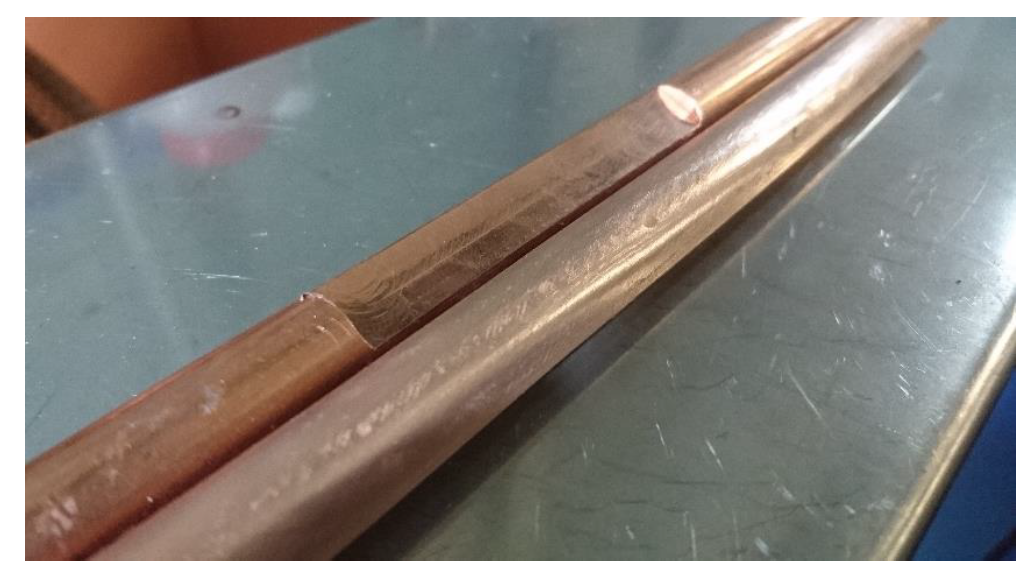
Tensile strength and breaking load of contact wires measured according to IEC 62917. The contact wire was pre-milled to a depth of 2 mm to simulate its wear. As a result, a 100 mm long and 10 mm wide area was obtained. Then part of the samples was tested to measure the tensile strength before spraying. Then the layers of the Cu-50% Al2O3 (corundum), Cu-60% Al2O3, Cu-50% Al2O3-5% Zn, Cu-50% Al2O3-10% Zn powder mixtures were sprayed on the milled surface of the other part of the contact wire samples. Figure 2 shows the contact wire samples before and after spraying.
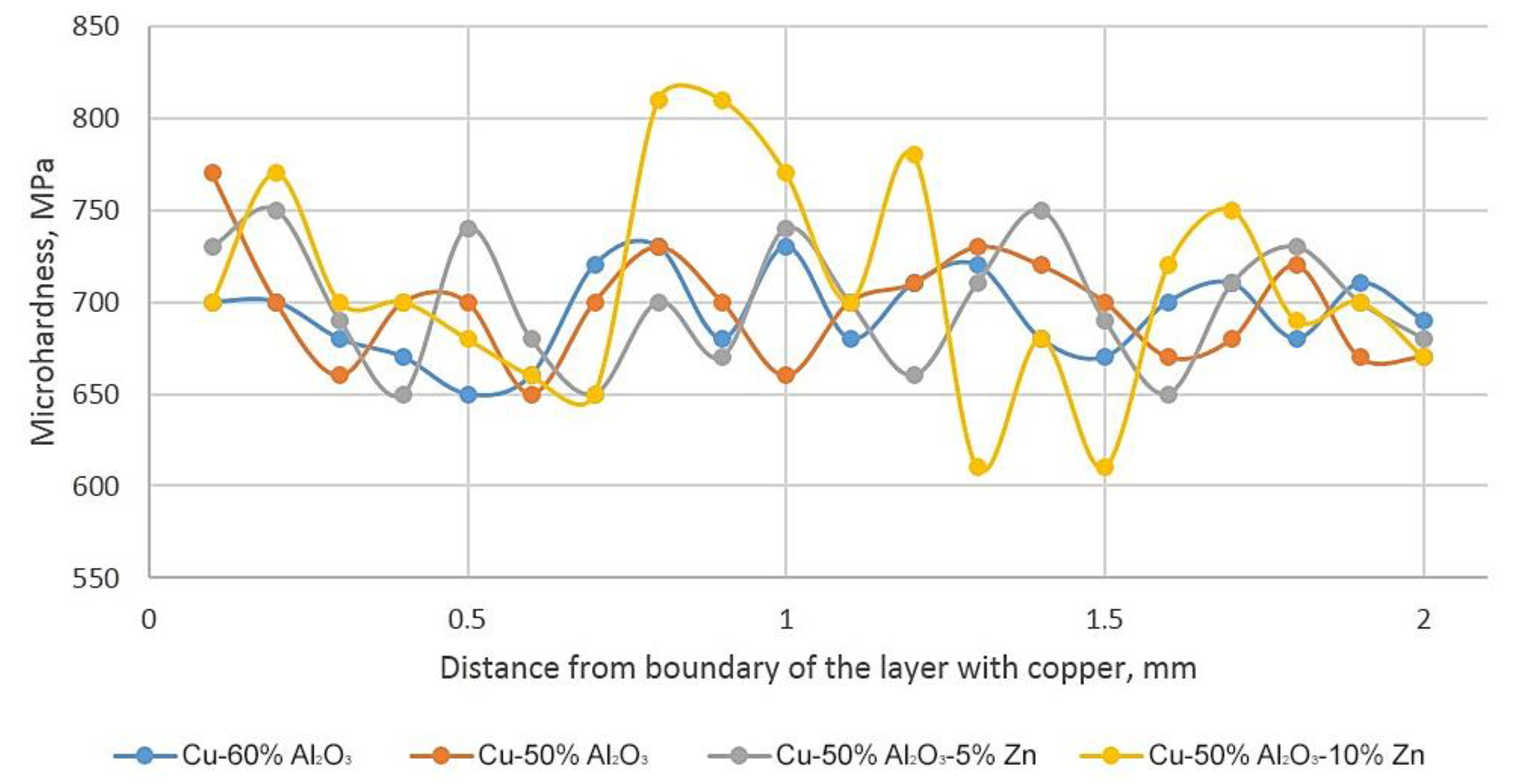
Microhardness of the substrate and sprayed layer was determined using a 50 g load. To determine the dependence of the microhardness value versus the distance from the board with the layer, the measurements were carried out in steps of 0.1 mm up to the distance of 2 mm. Microhardness was measured to study the possible softening of the subsurface layer of the contact wire up to 2 mm thick.
Spraying was carried out using a Dimet 405 (Joint-Stock Company DIMET, Russia). The temperature of the gas carrier (air) was 500 °C.
Metallographic specimens were made of the repaired wires and examined using an optical microscope and SEM. Using the specimens, microhardness values of the sprayed layer and contact wire were determined.
For the low temperature creep test, the 1500 mm long contact wire samples were used. Each sample was pre-milled in the middle for the depth of 2 mm and length of 250 mm. On areas simulating the local wear of the contact wire, the layers of the Cu-50% Al2O3 (corundum), Cu-60% Al2O3, Cu-50% Al2O3-5% Zn, Cu-50% Al2O3-10% Zn powder mixtures were sprayed. Then the tensile load of 180 MPa was applied to contact wire samples. Electric current was passed through samples of the contact wire, and as a result, they were heated to a temperature of 90 to 100 °C. The test duration was up to 720 h. The sample temperature was monitored using the TermoCAM S40 thermal imaging camera (FLIR Systems, Wilsonville, OR, USA). For qualitative determination of the temperature using this thermal imaging camera, individual areas of the contact wire samples were covered with a high-temperature varnish with the targeted coefficient of radiation. Figure 3 shows a typical contact wire thermogram during the low temperature creep test. To evenly distribute the temperature along the length, the sample was attached between two pieces of contact wires, each 20 m long, to which electric current was supplied. The free end of one 20 m piece of contact wire was attached to a dynamometer. The free end of another 20 m section was fixed rigidly. Using a dynamometer, the corresponding load was set. Elongation was measured on a 1.5 m contact wire sample. Based on the results of the low temperature creep test, elongation values of the contact wires were determined. Creep tests simulated the most severe operating conditions for contact wires. Tests for low temperature creep made it possible to study the effect of spraying on the operational durability of the contact wire.

3. Results and Discussion

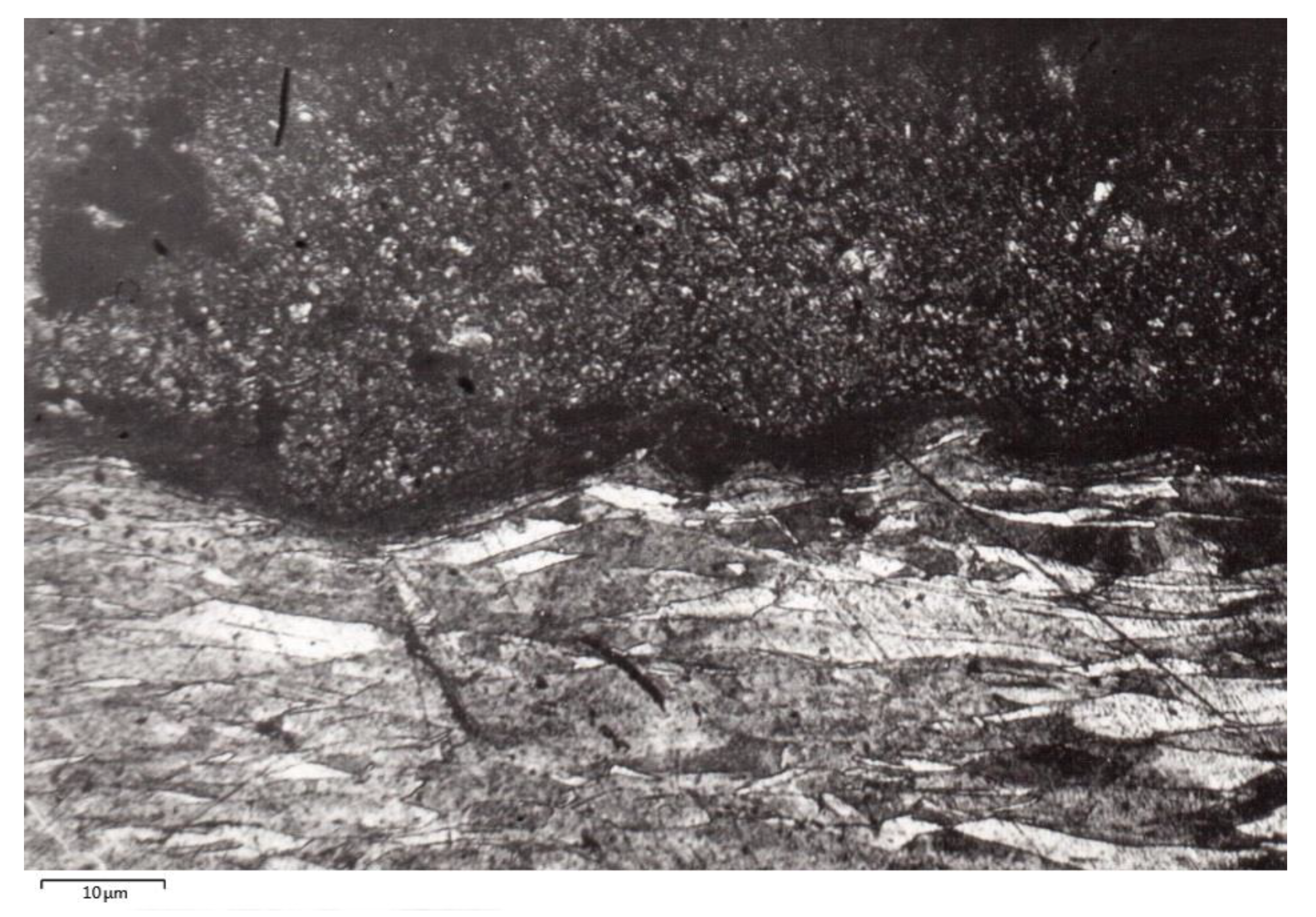
Figure 4, Figure 5, Figure 6, Figure 7, Figure 8, Figure 9, Figure 10, Figure 11 and Figure 12 show the results of metallographic and electron microscopic EBSD studies. Figure 4 shows the microstructure of the contact wire and sprayed layer. The specimen plane is parallel to the longitudinal axis of the wire.
In the lower part of Figure 4, grains elongated along the drawing direction are seen. No equiaxed grains that could be formed due to recrystallization are available. Hence, the subsurface layers of the contact wire bordering on the sprayed layer were not recrystallized. The contact wire crystallites retain the elongated form that is typical for drawing.
A contact wire sample with the layer of the Cu-50% Al2O3 powder mixtures sprayed at the temperature of 500 °C was examined by means of EBSD. The samples were examined along and transversely to the contact wire axis.
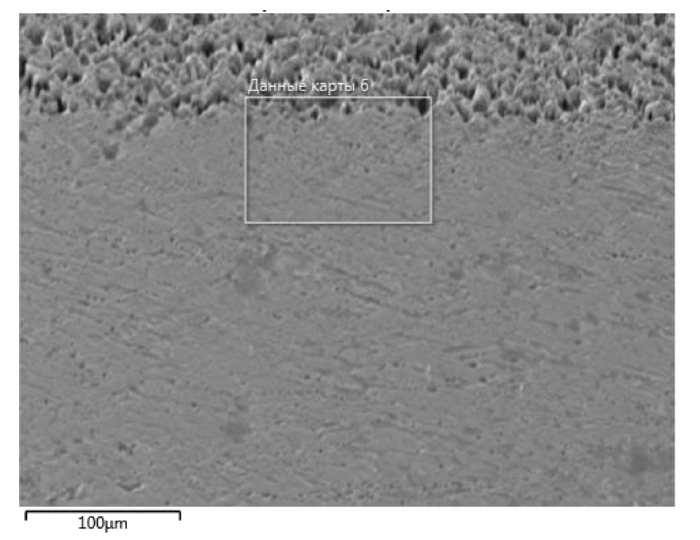
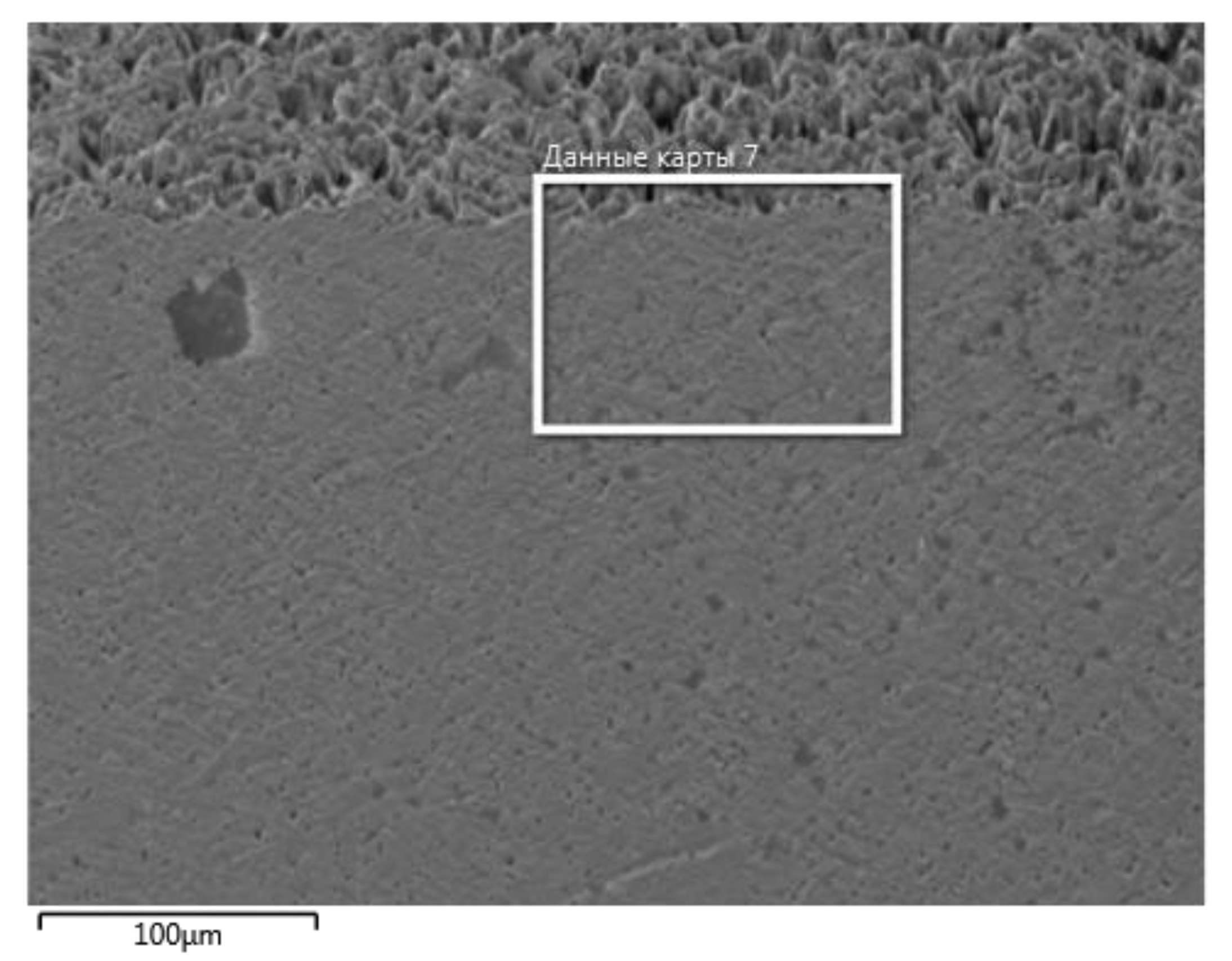
Figure 5 shows the area located along the wire near the boundary between the wire and sprayed layer.
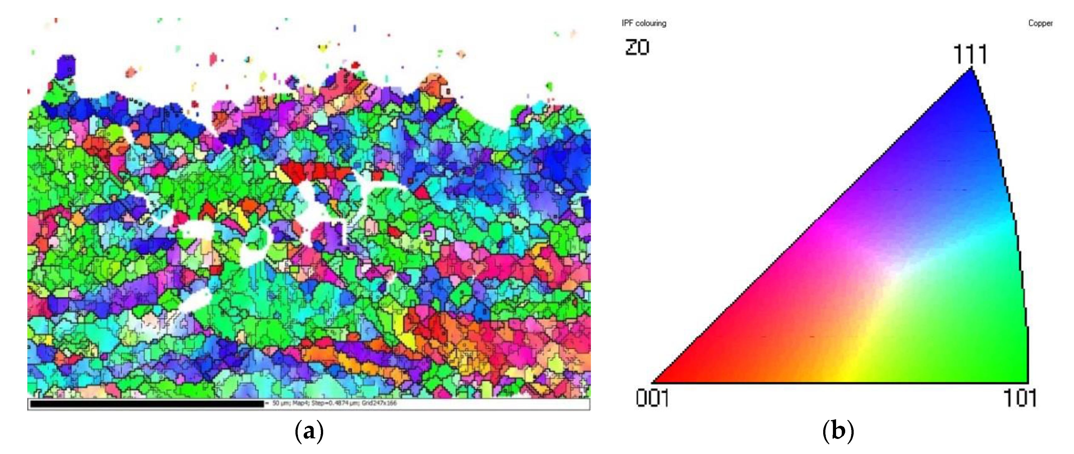
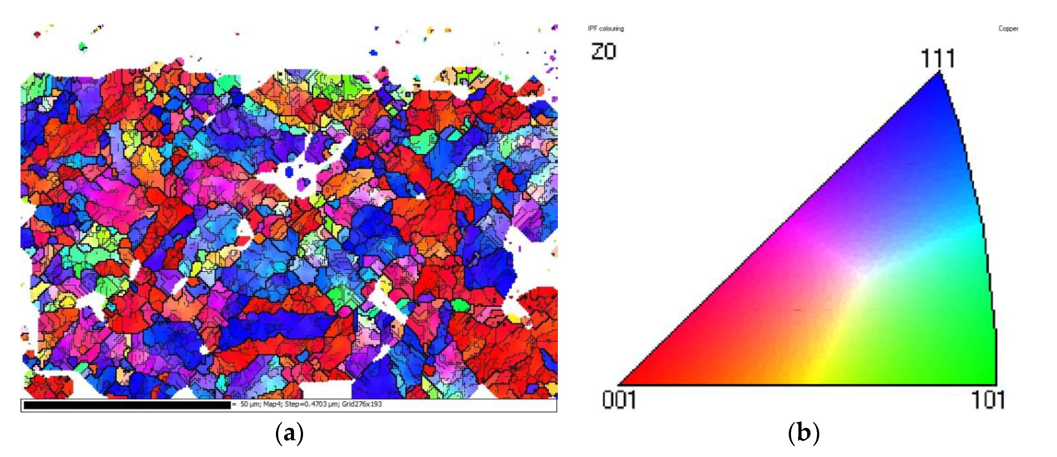
On Figure 6, distribution of orientation for crystallographic planes of copper grains near the boundary with the layer is shown mapped.
As shown in Figure 6, all of the copper grains are elongated along the contact wire axis. That grain form is typical for the texture of rolling with all-sided reduction or for that of drawing. In Figure 6, subdivision of the elongated grains into the sub-grains with low-angle boundaries is seen. The grains are oriented parallel to the wire axis, basically, by three crystallographic planes {001}, {101}, {111}. The grain form, subdivision of the grains into sub-grains, and orientation of crystallographic planes prove that recrystallization does not occur and the texture typical for pressure processing is retained.
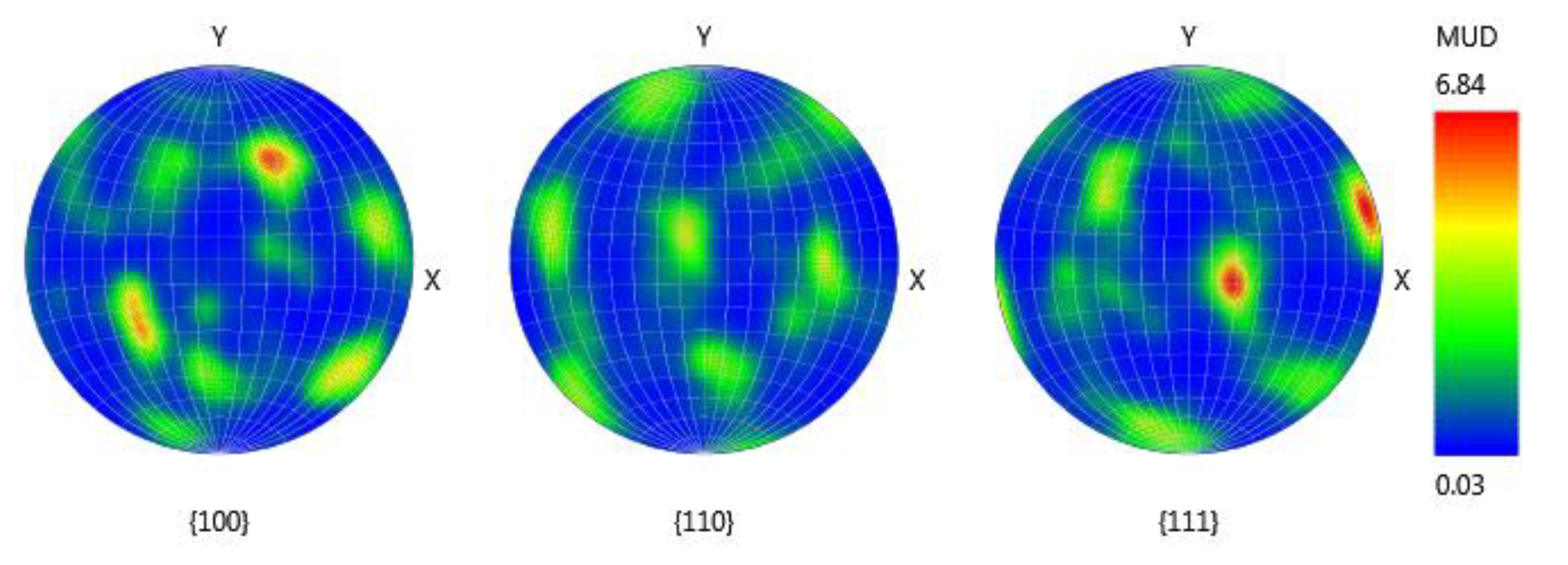
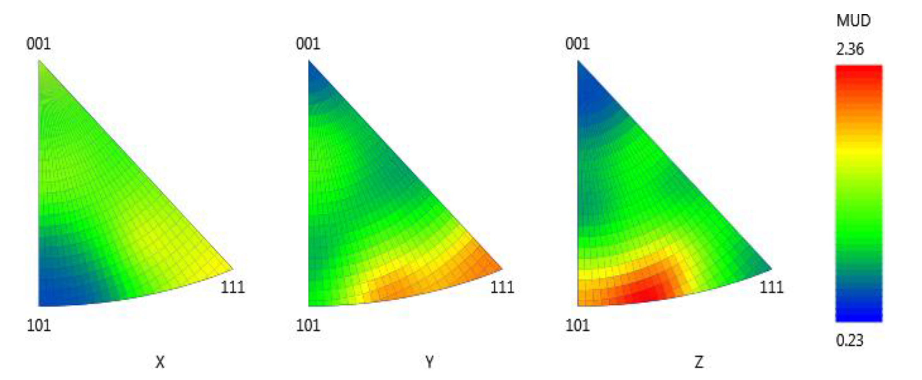
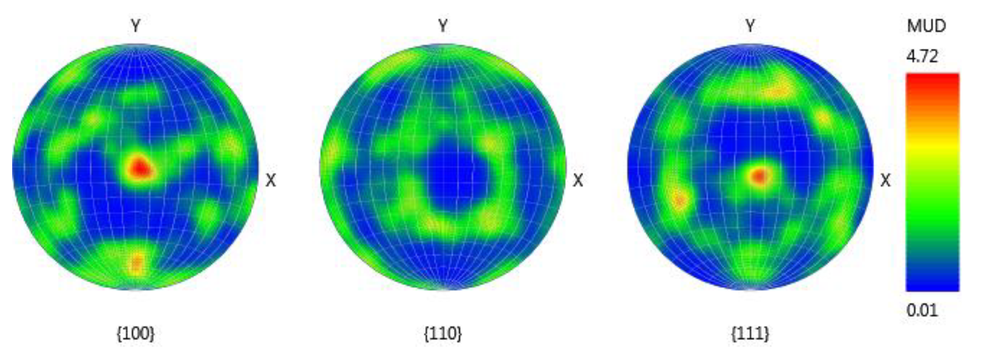
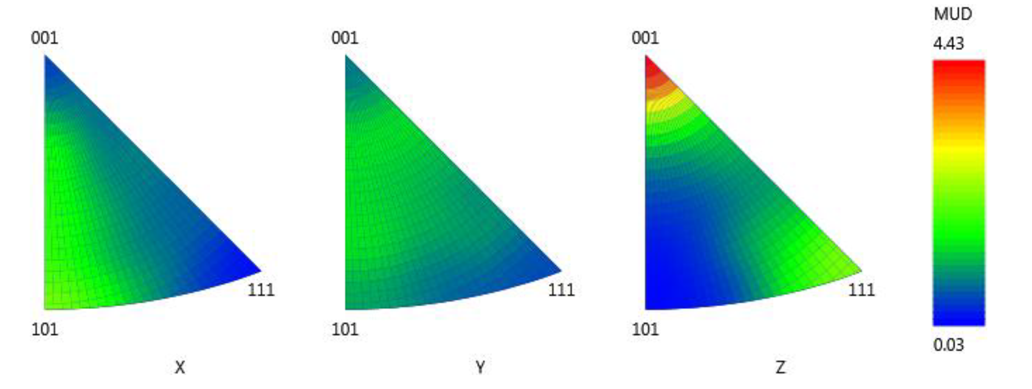
Figure 7 and Figure 8 show direct and inverse pole figures of the area shown in Figure 5 and Figure 6.
The pole figures in Figure 7 and Figure 8 show the typical texture of drawing or rolling with all-sided reduction. For example, it follows from the images of the inverse pole figures that along the X-axis (the direction parallel to the wire axis) crystallographic direction {111} typical for the drawing texture is most frequently oriented. The same conclusion holds for the direction parallel to plane {111} in the direction to X that coincides with the wire axis and with the drawing direction.
Figure 9 shows the area located perpendicularly to the wire axis near the boundary between the wire and sprayed layer.
On Figure 10, the distribution of orientation for crystallographic planes of copper grains near the boundary with the layer is mapped.
Only equiaxed grains are seen in Figure 10. Comparison of the grain forms in Figure 6 and Figure 10 indicates a columnar-grained structure. The said structure is typical for the texture of drawing or for that of rolling with all-sided reduction. The grains are subdivided into sub-grains. Hence, recrystallization did not occur.
Figure 11 and Figure 12 show direct and inverse pole figures of the area shown in Figure 10.
The pole figures in Figure 11 and Figure 12 show the typical texture of drawing or rolling with all-sided reduction. For example, it follows from the images of the inverse pole figures that the Z-axis (the direction parallel to the wire axis) coincides with direction {111}. This is typical for the texture of copper drawing.
Examinations of the copper structure of the contact wire after spraying show that recrystallization does not occur and that the drawing texture is retained.
Softening of subsurface layers of the contact wire due to spraying has been verified by means of micro-hardness measurement. Dependence of microhardness of copper of the contact wire on the distance from the border with the sprayed layer is shown in Figure 13. Measurement of the contact wire microhardness on the distance of 2 mm from the layer boundary has shown that recrystallization does not occur, since the microhardness value does not depend on the distance from the layer border and substrate. With recrystallization of the subsurface layers, the micro-hardness value must increase with the increasing distance from the boundary with the layer.
The contact wire strength retention was directly verified by means of the mechanical tensile test. The strength values of the contact wire before and after spraying were compared. The ultimate tensile strength values of the repaired and unrepaired contact wire samples are shown in Table 1.
As it shown in Table 1, the difference in the strength values is less than 1%, while the relative elongation of the repaired samples did not increase. Therefore, the strength values of the contact wire samples before spraying and after spraying do not actually differ from each other, and the relative elongation did not increase after spraying.
The elongation values of the repaired and unrepaired contact wire samples after the creep test are shown in Table 2.
The test results have proven that repair of worn contact wires does not result in their softening.
Coatings have practically no ductility, so they were destroyed before the plastic deformation of the contact wire. Therefore, the coatings did not affect the mechanical properties of the contact wire. The spraying process did not lead to recrystallization and softening of the contact wire, so it did not affect the mechanical properties of the contact wires.

4. Conclusions

Using the EBSD method (determining the misorientation of grains of a copper contact wire and constructing direct and inverse pole figures) and using the microhardness measurement, the absence of recrystallization in the contact wire zone near the sprayed layer has been shown.
Using mechanical tests, it was shown that spraying does not lead to a decrease in the tensile strength of the contact wire.
Using tests for low temperature creep, it was shown that sputtering does not lead to a decrease in the operational durability of the contact wire under severe operating conditions.
Application of the 2 mm thick layer on the surface of the copper contact wire by means of gas dynamic (cold) spraying at the air temperature of 500 °C does not result in recrystallization of the subsurface copper layers and loss of strength and high-temperature strength of the contact wire.

Author Contributions

Conceptualization, E.G. and I.G.; methodology, I.G. and E.G.; validation, P.P. and A.M.; formal analysis, A.M.; investigation, E.G. and P.P.; resources, P.P. and A.M.; data curation, E.G.; writing—original draft preparation, P.P.; writing—review and editing, I.G. and E.G.; visualization, E.G.; supervision, I.G. and A.M.; project administration, E.G. and P.P. All authors have read and agreed to the published version of the manuscript.

Funding

We would like to thank the Ministry of Science and Higher Education of the Russian Federation for supporting this work under the grant No. 075-15-2019-1254 with unique identification number RFMEFI57417X0179.

Conflicts of Interest

The authors declare no conflict of interest.

References

  1. Kuraoka, T.; Ideno, I. Research on Reduction of Wear of Contact Wires in Overlap Sections. 2012. Available online: https://www.semanticscholar.org/paper/Research-on-Reduction-of-Wear-of-Contact-Wires-in-Kuraoka-Ideno/de5b2d5c52f59fbbec279a7ecc1043262bd9975e (accessed on 16 December 2019).
  2. Shimizu, M. A Measure to Reduce Contact Wire Wear in Shinkansen Overlap Sections. 2004. Available online: https://www.rtri.or.jp/eng/publish/newsletter/pdf/06/RTA-06-38.pdf (accessed on 16 December 2019).
  3. Ikeda, K. Development of Method for Improving Overhead Line Equipment for Implementation of Stable Current Collection at High Speed. 2010. Available online: https://trid.trb.org/view/793419 (accessed on 16 December 2019).
  4. Nagasaka, S.; Aboshi, M. Measurment and estimation of contact wire unevenness. QR RTRI 2004, 45, 86–91. [Google Scholar] [CrossRef] [Green Version]
  5. Amari, S.; Tsunemoto, M.; Kusumi, S.; Kuraoka, T.; Hamada, T.; Minamoto, M. Evaluation of resistance at supporting pulley of messenger wire and its inluance on current collection characteristics. QR RTRI 2009, 50, 137–143. [Google Scholar] [CrossRef] [Green Version]
  6. Sugahara, A. Reduction of contact wire strain near dead sections by considering sliding level differences. QR RTRI 2004, 45, 75–79. [Google Scholar] [CrossRef]
  7. Biesenack, H.; Biesenack, H.; Pintscher, F. Kontakt Zwischen Fahrdraht und Schleifleiste-Ausgangspunkte zur Bestimmung des Elektrischen Verschleißes Elektrische Bahnen; Oldenbourg Industrieverlag GmbH: München, Germany, 2005; pp. 138–146. [Google Scholar]
  8. Iosif, S.; Gershman, E.; Fox-Rabinovich, G.; Veldhuis, S. Description of seizure process for gas dynamic spray of metal powders from non-equilibrium thermodynamics standpoint. Entropy 2016, 18, 315. [Google Scholar]
  9. Moridi, A.; Hassani-Gangaraj, S.M.; Guagliano, M.; Dao, M. Cold spray coating: Review of material systems and future perspectives. Surf. Eng. 2014, 36, 369–395. [Google Scholar] [CrossRef]
  10. Champagne, V.; Helfritch, D. Fundamentals of Cold-Gas Dynamics Spray; Woodhead Publishing: Cambridge, UK, 2007; p. 427. [Google Scholar]
  11. Irissou, E.; Legoux, J.G.; Arsenault, B.; Moreau, C. Investigation of Al-Al2O3 cold spray coating formation and properties. In Proceedings of the International Thermal Spray Conference, Beijing, China, 14–16 May 2007; ASM International: Cleveland, OH, USA, 2007; pp. 210–216. [Google Scholar]
  12. Wu, J.; Fang, H.; Yoon, S.; Kim, H.J.; Lee, C. Measurement of particle velocity and characterization of deposition in aluminum alloy kinetic spraying process. Appl. Surf. Sci. 2005, 252, 1368–1377. [Google Scholar] [CrossRef]
  13. Jen, T.C.; Li, L.; Cui, W.; Chen, Q.; Zhang, X. Numerical investigations on cold gas dynamic spray process with nano- and microsize particles. Int. J. Heat Mass Transf. 2005, 48, 4384–4396. [Google Scholar] [CrossRef]
  14. Jodoin, B.; Raletz, F.; Vardelle, M. Cold spray modeling and validation using an optical diagnostic method. Surf. Coat. Technol. 2006, 200, 4424–4432. [Google Scholar] [CrossRef]
  15. Vinnicki, M.; Piwowarczyk, T.; Malachowska, A. General description of cold sprayed coatings formation and of their properties. Bulletin of the pjlish academy of sciences. Tech. Sci. 2018, 66, 301–310. [Google Scholar]
  16. Gopinath, M.; John Sujin Mon, T.S.; Glarance, J.; John Britto, X.; Dhakshnamoorthy, M. Ohtimization of copper particles deposition using cold spray process. Int. J. Innov. Res. Sci. Eng. Technol. 2015, 4, 4189–4200. [Google Scholar]
  17. Vinnicki, M.; Piwowarczyk, T.; Malachowska, A.; Ambroziak, A. Effect of gas pressure and temperature on stereometric properties of Al + Al2O3 composite coatings deposited by LPCS method. Arch. Metall. Mater. 2014, 59, 879–886. [Google Scholar] [CrossRef] [Green Version]
  18. Huang, G.; Wang, H.; Li, X.; Xing, L. Study on the growth of holes in cold spraying via numerical simulation and experimental methods. Coatings 2017, 7, 2. [Google Scholar] [CrossRef] [Green Version]
  19. Kim, D.-Y.; Park, J.-J.; Lee, J.-G.; Kim, D.; Tark, S.J.; Ahn, S.; Yun, J.H.; Gwak, J.; Yoon, K.H.; Chandra, S.; et al. Cold spray deposition of copper electrodes on silicon and glass substrates. J. Therm. Spray Technol. 2013, 22, 1092–1102. [Google Scholar] [CrossRef]
  20. Vo, P.; Poirier, D.; Legoux, J.-G.; Keech, P.G.; Doyle, D.; Jakupi, P.; Irissou, E. Development of Cold Spray Technology for Copper Coating of Carbon Steel Used Fuel Container Prototipes for CANDU Fuel; NWMO: Toronto, ON, Canada, 2015. [Google Scholar]
  21. Zahiri, S.H.; Fraser, D.; Gulizia, S.; Jahedi, M. Effect of processing conditions on porosity formation in cold gas dynamic spraying of copper. J. Therm. Spray Technol. 2006, 15, 422–430. [Google Scholar] [CrossRef]
  22. Raoelison, R.N.; Verdy, C.; Liao, H. Cold gas dynamic spray additive manufacturing today: Deposit possibilities, technological solutions and viable applications. Mater. Des. 2017, 133, 266–287. [Google Scholar] [CrossRef]
  23. Stoltenhoff, T.; Borchers, C.; Gärtner, F.; Kreye, H. Microstructures and key properties of cold-sprayed and thermally sprayed copper coatings. Surf. Coat. Technol. 2006, 200, 4947–4960. [Google Scholar] [CrossRef]
  24. Schmidt, T.; Assadi, H.; Gärtner, F.; Richter, H.; Stoltenhoff, T.; Kreye, H.; Klassen, T. From particle acceleration to impact and bonding in cold spraying. J. Therm. Spray Technol. 2009, 18, 794–808. [Google Scholar] [CrossRef] [Green Version]
  25. Borchers, C.; Gärtner, F.; Stoltenhoff, T.; Assadi, H.; Kreye, H. Microstructural and macroscopic properties of cold sprayed copper coatings. J. Appl. Phys. 2003, 93, 10064–10070. [Google Scholar] [CrossRef]
  26. McCune, R.C.; Donlon, W.T.; Popoola, O.O.; Cartwright, E.L. Characterization of copper layers produced by cold gas-dynamic spraying. J. Therm. Spray Technol. 2000, 9, 73–82. [Google Scholar] [CrossRef]
  27. Humphreys, F.J.; Hatherly, M. Recrystallization and Related Annealing Phenomena, 2nd ed.; Pergamon: Oxford, UK, 2004. [Google Scholar]
  28. Rokni, M.R.; Widener, C.A.; Crawford, G.A.; West, M.K. An investigation into microstructer and mechanical properties of cold sprayed 7075 Al deposition. Mater. Sci. Eng. A 2015, 625, 19–27. [Google Scholar] [CrossRef]
  29. Zou, Y.; Qin, W.; Irissou, E.; Legoux, J.-G.; Yue, S.; Szpunar, J.A. Dynamic recrystallization in the particle/particle interfacial region of cold sprayed nickel coating: Electron backscatter diffraction characterization. Scr. Mater. 2009, 61, 899–902. [Google Scholar] [CrossRef]
  30. Rafaja, D.; Schucknecht, T.; Klemm, V.; Paul, A.; Berek, H. Microstructural characterization of titanium coatings deposited using cold gas spraying on Al2O3 substrates. Surf. Coat. Technol. 2009, 203, 3206–3213. [Google Scholar] [CrossRef]
  31. Cho, J.; Jin, Y.; Park, D.; Kim, H.; Oh, I.; Lee, K. Manufacture and properties of cold spray deposited large thickness Cu coating material for sputtering target. Met. Mater. Int. 2011, 17, 157–166. [Google Scholar] [CrossRef]
  32. Kang, K.; Park, H.; Bae, G.; Lee, C. Microstructure and texture of Al coating during kinetic spraying and heat treatment. J. Mater. Sci. 2012, 47, 4053–4061. [Google Scholar] [CrossRef]
  33. Zhang, Y.; Brodusch, N.; Descartes, S.; Chromik, R.R.; Gauvin, R. Microstructure refinement of cold-sprayed copper investigated by electron channeling contrast imaging. Microsc. Microanal. 2014, 20, 1499–1506. [Google Scholar] [CrossRef]
Figure 1. Sample of repaired contact wire (transversely to the axis): light area (top part)—sprayed layer, orange area (bottom part)—copper of contact wire.
Coatings 10 00007 g001
Figure 2. Contact wire samples having simulated local wear and repaired for tensile test.
Coatings 10 00007 g002
Figure 3. Readings of thermal imaging camera for contact wire samples during low temperature creep test.
Coatings 10 00007 g003
Figure 4. Microstructure of contact wire (below) and layer of 50% Cu + 50% Al2O3 powder sprayed at temperature of 500 °C (×500).
Coatings 10 00007 g004
Figure 5. Wire area near boundary with sprayed layer located parallel to wire axis. White rectangle is electron backscattered diffraction (EBSD)-analyzed area.
Coatings 10 00007 g005
Figure 6. (a) Orientation distribution map for crystallographic planes of copper grains (parallel to wire axis); (b) Colors associated with orientation directions.
Coatings 10 00007 g006
Figure 7. Direct pole figures of wire area shown in Figure 6a.
Coatings 10 00007 g007
Figure 8. Inverse pole figures of wire area shown in Figure 6a.
Coatings 10 00007 g008
Figure 9. Wire area near boundary with sprayed layer located perpendicularly to wire axis. White rectangle is EBSD-analyzed area.
Coatings 10 00007 g009
Figure 10. (a) Orientation distribution map for crystallographic planes of copper grains (perpendicularly to wire axis); (b) Colors associated with orientation directions.
Coatings 10 00007 g010
Figure 11. Direct pole figures of wire area shown in Figure 6a.
Coatings 10 00007 g011
Figure 12. Inverse pole figures of wire area shown in Figure 6a.
Coatings 10 00007 g012
Figure 13. Dependence of contact wire microhardness on distance from boundary with layers of various compositions sprayed at 500 °C.
Coatings 10 00007 g013
Table 1. Ultimate tensile strength values of repaired and unrepaired contact wire samples.
Composition of Powder Mixtures to be SprayedUltimate Tensile Strength, MPaRelative Elongation, %
Unrepaired362.54.6
Cu-50% Al2O3360.94.5
Cu-60% Al2O3362.74.3
Cu-50% Al2O3-5% Zn364.14.6
Cu-50% Al2O3-10% Zn362.24.1
Table 2. Elongation values of repaired and unrepaired contact wire samples after creep test.
Composition of Powder Mixtures to be SprayedElongation, mm
Unrepaired2.4
Cu-50% Al2O32.1
Cu-60% Al2O32.5
Cu-50% Al2O3-5% Zn2.1
Cu-50% Al2O3-10% Zn2.1