Article

Plasma Spray Coatings of Natural Ores From Structural, Mechanical, Thermal, and Dielectric Viewpoints

1
Institute of Plasma Physics, ASCR, Za Slovankou 3, 182 00 Prague 8, Czech Republic
2
Department of Electrotechnology, Faculty of Electrical Engineering, Czech Technical University, Technická 2, 166 27 Prague 6, Czech Republic
*
Author to whom correspondence should be addressed.
Coatings 2020, 10(1), 3; https://doi.org/10.3390/coatings10010003
Submission received: 30 October 2019 / Revised: 2 December 2019 / Accepted: 13 December 2019 / Published: 18 December 2019
(This article belongs to the Special Issue Advanced Coating for High Temperature Applications)

Abstract

:
Various natural materials, namely ilmenite, diopside, tourmaline, olivine, garnet, and basalt, were plasma-sprayed and analyzed. This paper summarizes the various achievements of our earlier research and adds new results—mainly dielectric and optical characterizations. Plasma spraying of all of the materials was rather easy with a high feed-rate plasma system, which could process many kilograms of powder per hour. For easier characterizations, the coatings were detached from substrates in order to remain self-supporting. The plasma-sprayed layers that were coated from all studied materials acted as medium-permittivity and low-loss dielectrics, antireflective optical materials, and medium quality anti-abrasive barriers. Phase composition and microhardness were evaluated in addition to microstructure observations. Some coatings were amorphous and crystallized after further heating. As the melting points were well above 1000 °C, all of them could also serve as thermal barriers for aluminum alloys and similar metals. The only material that was not easily sprayed was tourmaline, which gave very porous coatings without environmental barrier or dielectric characteristics.

1. Introduction

A variety of mineral and rock materials based on natural ores have been sprayed at the Institute of Plasma Physics in recent years by two similar plasma spraying techniques: water-stabilized plasma (WSP) and hybrid water–argon-stabilized plasma (WSPH) spraying. Both techniques can process a large quantity of material in a short timeframe compared to the majority of commercial torches used for plasma spraying. Natural materials offer comparable properties to synthetic ceramics or glass-ceramics in many aspects, or their “quality versus price” ratio is even better in selected cases. The Czech Republic has a rich tradition of making jewelry. Mining as well as processing of minerals for this purpose creates a substantial quantity of mineral powders, which are usually treated as waste. There are economic and environmental challenges related to reprocessing this waste and incorporating it into real components in industrial systems. Plasma spraying offers one of the useful paths for this revitalization process. The presented paper introduces and compares several mineral systems in the form of as-sprayed coatings and self-supporting bodies. In the following description of the individual minerals, we avoided their chemical use as photocatalysts (ilmenite) or chemical catalysts (ilmenite, diopside). This is because we targeted the spray process to achieve the best accessible mechanical properties and coating compactness, whereas chemical utilization is typically associated with an extremely high specific surface or foam-like character. This is a different task, with nearly opposite requirements.
Multiphase silicates and one titanate are the subject of the presented research. The minerals are ordered in the following order according to their decreasing ratios of oxygen versus Mg or Fe: olivine, ilmenite, diopside, garnet, tourmaline (which has structurally bonded OH groups), and basalt (which is a rock without a fixed chemical composition). Based on garnet’s components forming an amorphous bulk, basalt is listed last. This paper summarizes the various achievements of our earlier research and adds new results—mainly dielectric and optical characterizations of all the mentioned materials and all the results related to ilmenite.
Olivine (Mg,Fe)2SiO4, where Mg represents forsterite and Fe represents the fayalite component, is of geophysical interest because it is the principal mineral phase in the Earth's upper mantle [1]. The electrical resistivity of forsterite makes it a good insulator, similar to the synthetic oxides MgO or Al2O3. Impurity effects are probably the dominant electrical conduction processes in natural olivine crystals [1]. Since energy levels below 7.5 eV in olivine are due to iron, it is likely that electronic charge transport takes place through the interactions of localized electrons in impurity sites only [1].
The melting point of forsterite is about 1890 °C [2]. In the coatings, various microstructure features such as porosity [3] can hinder the effect of the electronic structure. The dielectric loss factor of sintered forsterite is low and almost constant at different frequencies [4]. Forsterite ceramic has been used in electronics because of its low relative permittivity εr and high resistance R [3,5,6]. Prolonged heating improves its crystallinity in order to form a SiO4 tetrahedral framework with 45% ionic bonds and 55% covalent bonds [5]. The covalent bond reduces εr, because of the high bond strength. The crystallinity of the plasma-sprayed coating [7] was much lower than that of the feedstock powder, as well as for typical sintered counterparts. Such ceramics exhibit free glass among grains [5].
Ilmenite FeTiO3, with a melting point of 1640 °C, is also a relatively refractory material compared to the other discussed minerals. Natural ilmenite is the most common mineral in titanium and it is used as a source of metallic titanium. The concentration of Ti in ilmenite is usually expressed as 53% of TiO2. Researchers have investigated reduction of ilmenite ore in a plasma jet using hydrogen as a reductant. Ilmenite is available abundantly in nature, whereas the availability of rutile TiO2 is very limited.
The existence of ilmenite in the X-ray diffraction XRD patterns was clearly shown from the presence of the (104) peak at 2theta = 32.65° [8]. Due to the iron species, FeTiO3 is a rather low-bandgap material, with a bandgap energy value of 2.58–2.90 eV [9].
Diopside forms solid solutions between CaMgSi2O6 and CaFeSi2O6. Diopside is common in metamorphic rocks, with a monoclinic crystal phase structure, and its melting point is about 1390 °C. The structure consists of single chains of SiO4 tetrahedra extending along the c-axis [10,11]. Among other purposes, it is suitable for ceramic glazes [12], as an addition to porcelain [13,14], for covering bone implants or dental implants [15,16] to improve their durability, and also as a host material for persistent luminescent nanoparticles [17]. Plasma-sprayed coatings of diopside have been elaborated previously [16]. The XRD pattern for diopside showed several low-intensity peaks of cristobalite (SiO2), and moreover the XRD indicated a partly amorphous composition [16].
Diopside is also suitable for the low-temperature, co-fired ceramic (LTCC) technology applied in the electrical industry for substrate materials [18,19,20]. Enhancing the microwave dielectric properties was reported to require an increase in crystallinity [21]. The relative permittivity of crystalline diopside was reported as 9.7 and loss factor was 0.0016, whereas for amorphous diopside the values were 8.9 and 0.0021, respectively [22]. Lower permittivity together with a higher loss factor represent worse dielectric behavior. This was reported [22] for amorphous materials. Particularly at low frequencies, the response of amorphous diopside to the external electric field was insufficient. Plasma spraying prepares coatings from amorphous silicate compositions for use on many substrate materials, without causing thermal damage [23,24,25].
Garnet materials as a group are relatively common in highly metamorphosed rocks. Their single crystals are hard, they have various colors with lack of cleavage, and they are durable. The general formula is A3B2(SiO4)3. A is in the formula for divalent elements such as iron, magnesium, calcium, and manganese, while B is for a trivalent metal such as aluminum, chromium, or iron. The main difference in physical properties among the members of the garnet group arises from variation in their density connected to the ratio of their components. Almandine Fe3Al2(SiO4)3 (“oriental garnet” in the gems field) and pyrope Mg3Al2(SiO4)3 (“bohemian garnet”) were sprayed by our group. The representatives of garnet in this paper are almandine-based.
Tourmaline (schorl) has a general chemical formula of NaFe3Al6(BO3)3Si6O18(OH,F)4. This material melts incongruently at temperatures varying roughly from 1050 to 1200 °C [26], whereas the melting point decreases with increasing content of iron or magnesium. Tourmaline’s density is 2.8 to 3.3 g.cm−3 (similar to diopside), dependent on actual iron-richness. An approximately 170 nm thick tourmaline film was deposited on glass by an ion-beam [27], however, nothing similar has been reported using plasma. Processing of material that melts incongruently (in the case of tourmaline, it is mainly because of the OH group in its structure) is a challenge for plasma spraying techniques. This is because for the spraying is typical a rapid quenching process, whereas the mentioned tourmaline features make them hypothetically suitable only for steady-state processes with slow, homogeneous heating and cooling.
Natural volcanic basalt rock powders can be used for glass-ceramic coatings without any nucleation agent (used for glass-ceramic production from glass frits), and the process would be substantially less expensive than glass-ceramics produced from pure oxides. Basalt contains SiO2, Al2O3, MgO, CaO, and iron oxides (FeO, Fe2O3), and also Na2O, K2O, P2O5, MnO, and TiO2 in small amounts [28,29]. Basalt as a surface protection for metals can be used wherever the transport of materials causes mechanical abrasion or chemical attack, as well as for mineral wool for heat, noise, and fire insulation [30].
We would like to summarize the results of these six natural materials to provide a reference for technologists' thinking about replacement of synthetic silicate ceramics with less expensive alternatives.

2. Materials and Methods

2.1. Sample Preparation

Stainless steel coupons were used as substrates for the formation of self-standing parts (SSP). The steel was grit-blasted using compressed air just before spraying. The substrates (300 °C) were preheated to provide better conditions for the coating crystallization, since this prolongs quenching. Coarse-grained natural ilmenite was crushed and sieved to obtain the feedstock powder for spraying (grain size 63–125 µm). The powder included a certain amount of impurities because of its natural character (0.5 wt.% CaO, 0.05 wt.% NiO). The powder was fed by compressed air through two injector tubes. In the spray process, the cooling setup consisted of a tube for a compressed air flow installed on the same robotic arm as the torch and repeating the torch movement pattern behind the plasma jet. During the spray process, the substrate was fixed (without any motion). The deposited coating thickness was about 3 mm and the layer was later removed from the substrate by thermal cycling at approximately −170/+100 °C. Details of (in principle very similar) spraying of other materials were reported in previous papers [31,32,33]. Morphologies of all feedstocks were similar to “fused and crushed” synthetic powders (not “agglomerated and sintered” powders). They were “fused” by nature and crushed during mining and post-processing. A comprehensive list of major spray parameters is provided in Table 1. The WSP technique involves plasma spraying with a water-stabilized “WSP” torch based on a liquid vortex in the plasma-forming channel instead of gas, which is used in common plasma torches. This instrument has high plasma enthalpy and high electrical power, and can be used in a high feed-rate spraying system for refractory materials. Because of the rather low mass flow rate of plasma composed purely of water, Ar gas is added in the stabilization channel, and this modification is called the “WSPH” technique. The velocity and temperature of particles in the plasma jet are enhanced by this setup. However, the plasma-forming medium is more expensive.

2.2. Characterization

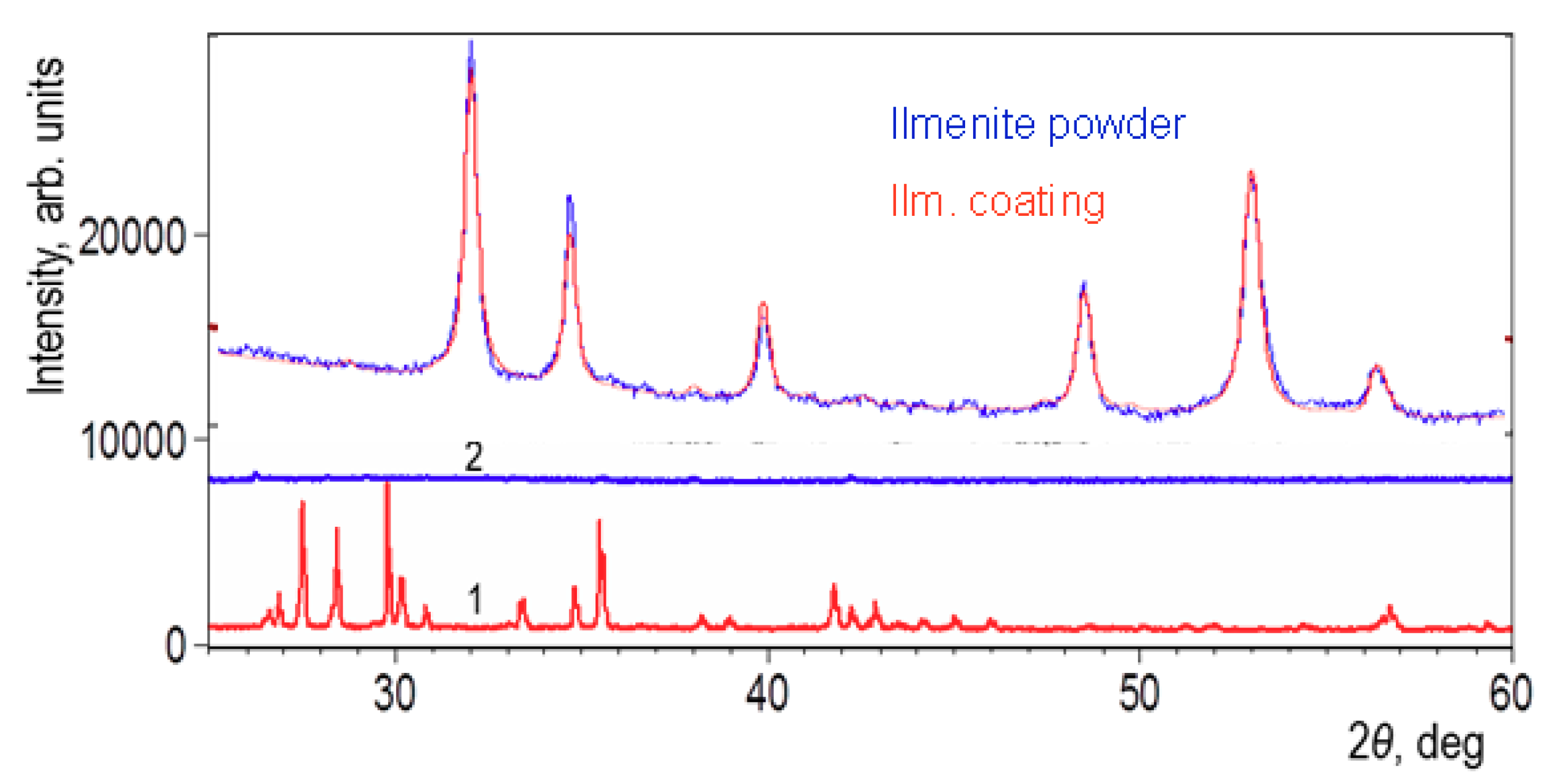
2.2.1. Phase Composition

Powder samples of the feedstock powder and sprayed coatings were analyzed by X-ray diffraction technique (D8 Discover, Bruker, Germany). Topas software was used for the quantitative Rietveld analysis. The crystallinity computation was based on integral intensities of crystalline phases and the amorphous halo only, since the amorphous material was assumed to be of the same chemical composition as the crystalline phase.

2.2.2. Thermal Analyses

The differential thermal analysis (DTA) curves were obtained by simultaneous thermal analyses (Thermogravimetry/DTA; Bähr, Selb, Germany) in argon atmosphere (flow rate 5 l/h) with a heating rate of 10 K/min. Before the measurement, powder samples for DTA were obtained by manual grinding the spray deposits after cutting the self-standing coatings. The measurements were performed with maximum temperature set to 1400 °C. The crystallization process usually manifested itself on the DTA curve as a strong sharp peak, and on the dilatometric curve as intensive shrinkage.
The thermal tests also included thermal expansion coefficient (TEC) measurements of samples, which were 12 to 13 mm long. The thermal dilatations were recorded at a 5 °C/min rate up to 1350 °C on a Setsys 16/18 vertical contact dilatometer (Setaram, France). The thermal expansion coefficients were calculated up to the crystallization or transformation temperature for each material.

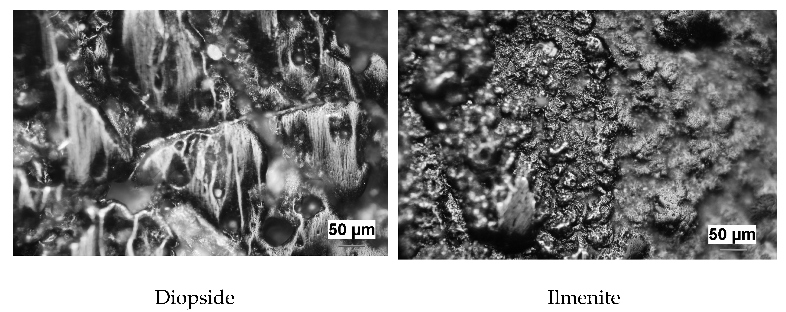
2.2.3. Microstructure

Selection of samples for microstructure study was done carefully to represent central parts of the planar coating far enough from edges. Polished cross-sections were prepared from as-deposited samples. Cutting was done using a diamond blade, subsequently the sections were mounted in a resin, and polishing was carried out using the Tegramin-25 automatic system (Struers, Denmark).

2.2.4. Porosity, Microhardness, and Roughness

Porosity was analyzed using the image analysis (IA) software (Lucia G, Laboratory Imaging, Czech Republic) on polished cross-sections. Micrographs were collected by an optical microscope (Zeiss, Germany) equipped with a digital camera. Porosity level was determined from images by differences in intensity of the reflected light (i.e., grey levels). Ten images of microstructures collected from various areas of the cross-section for each sample were analyzed. Besides porosity percentage, other features of the coatings were examined as well, including the number of voids per unit area (NV) of the section and the equivalent diameter (ED) of voids, which represents their size distribution. Circularity varied between 1 (i.e., a circle, which represents a globular pore) and 0 (i.e., a line, representing a flat pore or a crack). The resolution of the light microscope is already sufficient to provide quantification of the interlamellar pores, but not the ultra-fine vertical cracks, which are also often present in plasma-sprayed coatings [34].
Density was examined by helium pycnometry (AccuPyc 1330 V3.03), as well as by Archimedean (i.e., water immersion) techniques. A high-accuracy analytical balance TE214S machine (Sartorius, NY, USA) was used to weigh samples.
Vickers microhardness values of the coatings were measured on polished sections using a Hanemann head equipped with a Vickers indenter and installed on an optical microscope (Zeiss, Germany). A testing load of 1 N was applied over 15 s. The mean value of microhardness was calculated as an average from 20 indentations.
Surface roughness was monitored by a contact method using the Surtronic 3P (Taylor-Hobson, UK) apparatus on a path 13 mm long, repeated 5 times on parallel tracks. The Ra parameter was collected to characterize coating materials.

2.2.5. Wear Resistance

The wear behavior of the coatings was examined by testing their slurry abrasion response (SAR) with respect to the ASTM standard [35]. The SAR test is based on recording the mass loss rate of a standard-shaped block while is it immersed in a slurry and shifted about 30 cm there and back. The slurry consisted of equal amounts of water and Al2O3 powder, whereas powder with size between 40 and 50 µm size was used. The whole test was run for more than 9 kilometers in 4 equal increments (runs) with an applied force of 22 N per specimen. After each run, the specimens were ultrasonically cleaned and weighed. The standard [35] prescription to use 4 identical samples of each material was fulfilled. The results are expressed as inverse wear rate (IWR), which represents the length of path necessary to wear out one cubic millimeter of the material. The higher the IWR, the better the wear resistance is.

2.2.6. Dielectric Measurements
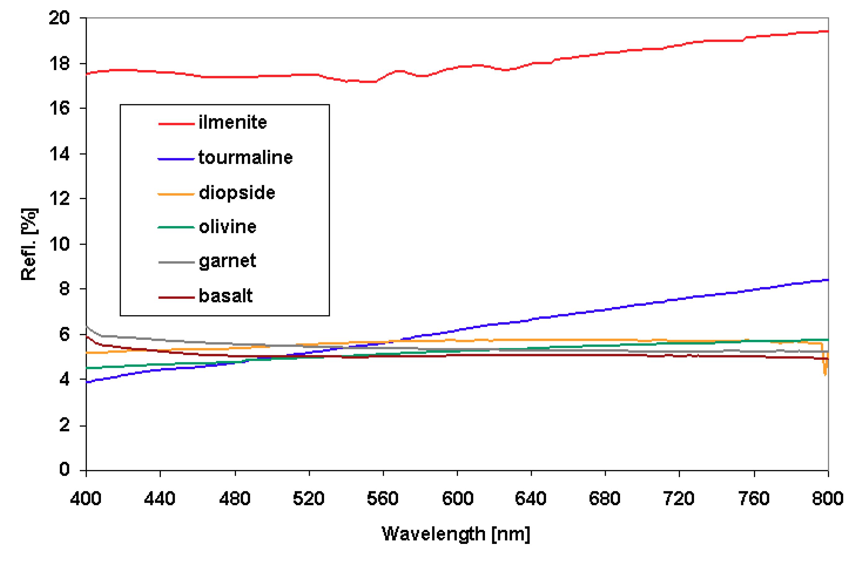
Aluminum metal was sputtered in a reduced pressure chamber onto both sides of each sample to serve as thin film electrodes. A three-electrode arrangement was used to measure the dielectric parameters. The electric field was applied parallel to the spray direction (i.e., perpendicular to the substrate surface).
Capacitance was recorded at room temperature in the frequency range from 100 Hz to 100 kHz using a programmable impedance analyzer model 4284A (Agilent, USA) at 1 V AC voltage. Relative permittivity εr was calculated from measured capacity CP and known specimen dimensions. Simultaneously, the loss tangent was measured using the same arrangement and equipment.
Electric resistance was measured at room temperature with a special resistivity adapter Keithley 6105. The DC electric field was applied from a regulated high-voltage source and the values recorded by a multi-purpose electrometer (617C, Keithley Instruments, USA). The magnitude of the applied voltage was 100 ± 0.05 V. Volume resistivity was calculated from the measured resistance and known specimen dimensions.

2.2.7. Reflectance

Diffuse reflectance spectrometry provides an excellent alternative to transmission spectrometry for measuring samples that are not suitable for the preparation of a transparent disc. The most significant assumption is the isotropic scattering within the sample. Reflectance measurement was done using an ultraviolet/visible/near-infrared (UV/Vis/NIR) spectrophotometer (3100 Version, Shimadzu, Kyoto, Japan). The calibration was performed using a BaSO4 reference mirror. The wavelength of incident radiation was continuously varied in the range of 400 to 800 nm, whereas the diameter of the measured area was about 2 cm2.

3. Results and Discussion

3.1. Microstructure and Porosity

Micrographs of the cross-sections are shown in Figure 1. Spray setup optimization was done as described in pervious papers [31,32,33]. Spraying of individual particles was done for optimization. Two spraying methods are commonly used: (i) Spraying onto glass and then observing individual droplet shapes as they flatten. If they are very irregular and not flat, then melting is incorrect and feeding distance, torch power, powder feed rate, or a combination of these factors were set incorrectly. (ii) Spraying in a container with a cold liquid to “freeze” the individual droplets and collect them. If they are not spherical, then melting is incorrect and the feeding tube radial position, torch power, powder feed rate, or a combination of these factors were set incorrectly. The full complexity of such elaborations is outside the scope of this paper.
Porosity appears as black areas in the micrographs. In addition to pores, a lot of cracks are vertically aligned, and also branch-like cracks are visible. According to the micrographs, the coatings can be roughly sorted into three groups. In the first group, ilmenite and olivine exhibit the typical lamellar microstructure of plasma-sprayed ceramics. Short and longer vertical cracks are numerous, along with pores with a globular character. Diopside and tourmaline exhibit more large pores, some of which are nearly 100 µm in diameter. Fine vertical cracks seem to absent. Garnet and basalt show very good interlamellar contact, with only few pores that are rather small and not interconnected. The differences appear mainly because of the different melt viscosities of each material. For example, the viscosity of molten basalt is reported to be exceptionally high [36]. Various porosity aspects are summarized in Table 2.
Plasma-sprayed almandine garnet in some cases reached an exceptionally low porosity of 2%, while that of basalt was around 3%. The main reason behind these low values of porosity is the amorphous character of the coatings. In addition, most of the pores are closed spheres, where gas was probably entrapped (bubbles), and they are not interconnected—especially in basalt.

3.2. Phase Composition

X-ray diffraction (XRD) results are summarized in Table 3. It is interesting to note that basically two types amorphousness character emerged: one with amorphous "halos" [37], and the other one without any distinguishable intensity maxima [29], as seen for almandine garnet and basalt. No intensity maxima were found in the coatings, where the cooling rate was lower. In several samples, lower concentrations of silicon and alkali elements were found after spraying compared to the feedstock powder. For example, garnet powder contained 33.2 wt.% SiO2, whereas the coating only contained 29.7 wt.%. Basalt powder 49.4 wt.% SiO2 and the coating only contained 46.0 wt.% (X-ray fluorescence analysis).
The XRD results indicated an ilmenite FeTiO3 phase in the coating only (Figure 2). Among all coatings, only this one was fully crystalline immediately after spraying. The lattice parameters were a = 0.50766(4) nm and c = 1.39786(13) nm. Olivine was partly amorphous after spraying (Figure 3).

3.3. Mechanical Properties

Microhardness, wear resistance (IWR), and surface roughness are listed in Table 4. The following relations are described first for tourmaline, which is exceptional among the samples. It represents a “lower quality coating” than the majority of the tested materials. The IWR of tourmaline was the worst, because of the excessively high porosity and evidently poor cohesion (observed while sectioning and grinding) of this coating. However, it was relatively hard and locally tough (most probably due to the isolated “islands” of rutile TiO2), and its microhardness was comparable with ilmenite and diopside, and higher than that of basalt.
The circularity of voids in tourmaline was the lowest. In combination with its high number of voids per square millimeter means that cracks and large elongated pores (both strongly deteriorating the mechanical behavior) were numerous. This is because the cracks have low circularity. Large pores also have low circularity if are they elongated. Fine pores, near the resolution limit of this technique, are less suitable for expression of the circularity parameter, because few pixels represent the object. One pixel is a “circle” and two pixels are a “line” (i.e., markedly bigger objects can only be truly represented by such a parameter).
For ilmenite, which was never published among our materials, the porosity is low and the number of voids per square unit is high. This means that the pores are small and frequent. The equivalent diameter was, in accordance with this assumption, smaller than for tourmaline. The wear resistance of ilmenite was the highest of all samples, owing to its low-porosity microstructure.
Basalt had similar microhardness as the plasma-sprayed basalt reported elsewhere [28], with a value of about 6.7 GPa.
Concerning the surface roughness, there were serious differences between the materials. Ilmenite looked smooth and “metal-like”, and its roughness was under 10 µm. Diopside was more than five times coarser. First of all, the feedstock powder size was 100–180 µm for diopside and 63–125 µm for ilmenite, which was the reason for this difference. Ilmenite, the higher melting point material, had a powder size that was too fine for it to be molten completely.
The wear resistance of ilmenite (Figure 4) represents the dependence of the volume losses on the distance passed in the slurry. It exhibits nearly linear curve (typical for all studied materials). This is a sign of a uniform coating character within the entire thickness. The wear resistance, expressed as inverse wear rate (IWR), determined by the slurry test, was relatively higher for olivine than the other sprayed coatings made from natural powders: ilmenite = 46.1 m/mm3, diopside = 35.6 m/mm3 [31], basalt = 42 m/mm3, garnet = 45 m/mm3, tourmaline = 15 m/mm3, and olivine = 62.8 m/mm3 [32]. This could be because of the rather high hardness of sprayed olivine (Vickers microhardness HVm = 8.39 ± 1.11 GPa). Differences in the densities are the result of the crystalline-to-amorphous transformation during spraying. Amorphous materials are, in principle, less dense than their polycrystalline counterparts. On the other hand, they are typically harder. With this in mind, the amorphous materials after spraying of crystalline powder (diopside) were rather hard (Table 4), but not particularly wear-resistant. Basalt feedstock is amorphous, and therefore its density and the density of the coatings were practically the same. Its rather low microhardness and high wear resistance are associated with this attribute.
The diopside surface after the SAR test is displayed in Figure 5. The movement direction during the test is aligned vertically in the figure. Open pores and bubbles can be seen (circular, seen near the scale bar), as well as coarse and deep removals of the material. The small, flat areas are rather smooth, with fine pits only (i.e., small dots; several of them can be seen above the scale bar). In contrast, ilmenite shows a more dross-like deformed surface, representing crushing of individual lamellas. Diopside had higher microhardness but lower wear resistance. The damage of diopside is more “brittle” and that of ilmenite is more “ductile”. A smaller flattening ratio of splats in olivine coatings leads to higher occurrence of intersplat decohesion [38], whereas the presence of intrasplat cracks was rare.

3.4. Dielectric Properties

Ilmenite, garnet, olivine, and diopside were measured, whereas basalt was conductive, “similar to metal”. For such a material, expression of permittivity and losses would be physically incorrect. Tourmaline was too porous and fragile for correct sputtering of electrodes or application of the contact force by the fixture (“clamping”) in the dielectric measurement.
The relative permittivity of the studied materials depends slightly on frequency (Figure 6), as expected based on the theory [39]. Garnet and diopside have permittivity similar to plasma-sprayed or sintered aluminum oxide—a typical “medium permittivity” material. Olivine, and particularly ilmenite, have higher relative permittivity. However, for ilmenite, the high permittivity is associated with high loss factor at low frequencies. This is because of space charge polarization of Fe-containing species. Surprisingly, diopside has even higher losses at low frequencies. Structural inhomogeneity, represented by rather large pores (see Table 2), is responsible for this. However, at frequencies above 15 kHz, all materials exhibit a loss factor (Figure 7) of approximately 0.02, which is an acceptably low value when compared with plasma-sprayed synthetic silicates [40]. Also, the resistivity (Table 5) in order of magnitude of 109 Ωm or higher is fully comparable with the synthetic silicates [40].
The concentrations of electrons and electron defects in ilmenite are much larger than those of the ionic defects [41]. In this case, the disorder of electrons is not influenced by small deviations from ideal stoichiometry.

3.5. Thermal Properties

The thermal characteristics of the powders and coatings are displayed in Table 6. The thermal expansion coefficients (TEC) of ilmenite and olivine are ten times larger than the TEC of tourmaline (however, for tourmaline is it determined only at room temperature). All partially amorphous coatings crystallize or react during the first heating. In case of tourmaline, this is a reaction to the OH groups' release and disproportionation of NaO groups. For diopside, the reason is the separation of CaO. The glass transition (Tg) and crystallization (Tp) temperatures of plasma-sprayed basalt were found by other authors to lie near 806 °C and 820 °C, respectively [28].
Olivine partly crystallized above 890 °C to enstatite. Ilmenite did not show any phase transformation. Since it is crystalline in the as-sprayed form, this is the most thermally stable substance among the studied materials. The fully amorphous diopside coating crystallized above 800 °C (Figure 8) to diopside. Tourmaline’s partly crystalline coating crystallized above 890 °C to tourmaline (with traces of rutile TiO2). Garnet’s partly crystalline coating crystallized above 800 °C to almandine (with traces of quartz SiO2). Basalt’s fully amorphous coating crystallized above 700 °C to almandine (with traces of magnetite Fe3O4 and quartz SiO2; other components were not identified).

3.6. Optical Properties

All studied coatings, with the exception of ilmenite, are very antireflective materials (Figure 9). This corresponds with the fact that all of them are black or dark grey in visible light. Ilmenite exhibits a luster typical of “metal-like” substances, probably because of the Fe species. Synthetic ilmenite (a product of the company Aldrich) exhibited reflectivity equal to only 7% of the BaSO4 standard in the range of 300 to 800 nm [9]. Materials exhibiting such low and wavelength-stable reflectivity are “large bandgap materials”, and optical measurements are not suitable tools for bandgap estimation. Forsterite (olivine) was mentioned as a “wide-gap insulator” [1], and this is fully in accordance with its low reflectivity (Figure 9).

4. Conclusions

Various natural materials, namely ilmenite, diopside, tourmaline, olivine, garnet, and basalt, were plasma-sprayed and analyzed. According to the microstructure, the coatings can be roughly organized into three groups. Ilmenite and olivine exhibited lamellar characters, as is typical for plasma-sprayed ceramics. Diopside and tourmaline exhibited more numerous large pores, some of which were nearly 100 µm in diameter. Fine vertical cracks seemed to absent. Garnet and basalt showed very good interlamellar contact, with only few pores that were not interconnected. Ilmenite was fully crystalline after spraying, while other materials were partly amorphous; basalt was fully amorphous. Porosity content was the lowest for garnet (3%) and the highest for tourmaline (16%). The microhardness was comparable with synthetic silicates, while wear resistance was better than for glass. Dielectric properties were partly instable at low frequencies, but at 100 kHz and above the loss factor was low at about 0.02, which is very good considering the limited purity of the natural materials. The described materials, particularly olivine and garnet, could replace synthetic silicates in some applications, for example replacing cordierite or steatite, which have similar dielectric properties (in sprayed as well as bulk forms [40]), but whose processing from raw form into adequate quality chemicals is more expensive. Spraying of olivine was successfully tested by a variety of plasma torches [32,42].
Tourmaline exhibited low thermal expansion of only 1 × 10⁻⁶ per kelvin, while olivine showed a value more than 10 times higher, and other materials were in between. The coatings could serve as barriers (environmental or thermal) up to 800 °C or slightly more (except basalt, which could only go up to 700 °C), without causing unwanted reactions or pronounced shrinkage. Several of them could form capacitor design systems together with metals. All coatings, with the exception of ilmenite, were strongly antireflective in visible and near-infrared ranges.

Author Contributions

Conceptualization, P.C.; methodology, P.C.; Software, J.S.; validation, K.N.; formal analysis, P.C.; Investigation, B.N. and J.P.; resources, B.N.; Data curation, J.S. and J.P.; Writing—original draft preparation, P.C.; Writing—review and editing, P.C. All authors have read and agreed to the published version of the manuscript.

Funding

This research received no external funding.

Acknowledgments

The authors would like to thank to all XRD operators: J. Dubský, Z. Pala, and F. Lukáč. Institute of plasma physics ASCR paid for all the used starting materials.

Conflicts of Interest

The authors declare no conflict of interest.

References

  1. Shankland, T.J. Synthetic forsterite. Bull. Am. Ceram. Soc. 1967, 46, 1160–1168. [Google Scholar]
  2. Bouhifd, M.A.; Andrault, A.; Fiques, G.; Richet, P. Thermal expansion of forsterite upto the melting point. Geophys. Res. Lett. 1996, 23, 1143–1146. [Google Scholar] [CrossRef]
  3. Cojocaru, C.V.; Lamarre, J.M.; Legoux, J.G.; Marple, B.R. Atmospheric Plasma-sprayed Forsterite (Mg2SiO4) Coatings: An Investigation of the Processing-Microstructure-Performance Relationship. J. Therm. Spray Technol. 2013, 22, 145–150. [Google Scholar] [CrossRef]
  4. Pospisil, Z.; Koller, A. Fine Ceramics, 1st ed.; SNTL: Prague, Czech, 1981. [Google Scholar]
  5. Ohsato, H.; Tsunooka, T.; Sugiyama, T.; Kakimoto, K.; Ogawa, H. Forsterite ceramics for millimeterwave dielectrics. J. Electroceram. 2006, 17, 445–450. [Google Scholar] [CrossRef]
  6. Han, C.S.; Mohanty, B.C.; Choi, H.R.; Cho, Y.S. Surface scaling evolution and dielectric properties of sputter-deposited low loss Mg2SiO4 thin films. Surf. Coat. Technol. 2013, 231, 229–233. [Google Scholar] [CrossRef]
  7. Xie, Y.; Zhai, W.; Chen, L.; Chang, J.; Zheng, X.; Ding, C. Preparation and in vitro evaluation of plasma-sprayed Mg2SiO4 coating on titanium alloy. Acta. Biomater. 2009, 5, 2331–2337. [Google Scholar] [CrossRef]
  8. Lee, R.B.; Juan, J.C.; Lai, C.W.; Lee, K.M. Ilmenite: Properties and photodegradation kinetic on Reactive Black 5 dye. Chin. Chem. Lett. 2017, 28, 1613–1618. [Google Scholar] [CrossRef]
  9. Gao, B.; Kim, Y.J.; Chakraborty, A.K.; Lee, W.I. Efficient decomposition of organic compounds with FeTiO3/TiO2 heterojunction under visible light irradiation. Appl. Catal. B 2008, 83, 202–207. [Google Scholar] [CrossRef]
  10. Cano, N.F.; Yauri, J.M.; Watanabe, S.; Mittani, J.C.R.; Blak, A. Thermoluminescence of natural and synthetic diopside. J. Lumin. 2008, 128, 1185–1190. [Google Scholar] [CrossRef]
  11. Ito, M.; Morioka, M. Growth of diopside (CaMgSi2O6) single crystal by the Czochralski technique. Geochem. J. 2006, 40, 625–629. [Google Scholar] [CrossRef]
  12. Romero, M.; Rincon, A.; Acosta, A. Effect of iron oxide content on the crystallization of a diopside glass-ceramic glaze. J. Europ. Ceram. Soc. 2002, 22, 883–890. [Google Scholar] [CrossRef] [Green Version]
  13. Bozadjiev, L.S.; Bozadjiev, R.L.; Georgiev, G.T.; Doncheva, L.S. Diopside Porcelain Tile. Bull. Am. Ceram. Soc. 2006, 85, 12–9101. [Google Scholar]
  14. Kostikov, K.S.; Pogrebenkov, V.M.; Vereshchagin, V.I. Diopside—the prospective compound of ceramics. In Proceedings of the KORUS 01—Proceedings of the Fifth Russian-Korean International Symposium on Science and Technology, Tomsk, Russia, 16–20 June 2001; Volume 2. [Google Scholar]
  15. Razavi, M.; Fathi, M.; Savabi, O.; Vashaee, D.; Tayebi, L. In vitro study of nanostructured diopside coating on Mg alloy orthopedic implants. Mater. Sci. Eng. C 2014, 41, 168–177. [Google Scholar] [CrossRef] [PubMed]
  16. Xue, W.; Liu, X.; Zheng, X.; Ding, C. Plasma-sprayed diopside coatings for biomedical applications. Surf. Coat. Technol. 2004, 185, 340–345. [Google Scholar] [CrossRef]
  17. Maldiney, T.; Lecointre, A.; Viana, B.; Bessiere, A.; Gourier, D.; Bessodes, M.; Cyrille, R.; Sherman, D. Trap depth optimization to improve optical properties of diopside-based nanophosphors for medical imaging. In Proceedings of the Oxide-based Materials and Devices III, San Francisco, CA, USA, 29 February 2012. [Google Scholar] [CrossRef]
  18. Choi, B.K.; Sun, G.N.; Kim, E.S. Microwave dielectric properties of diopside glass-ceramics. Ceram. Int. 2013, 39, 677–680. [Google Scholar] [CrossRef]
  19. Feng, K.C.; Chou, C.C.; Chu, L.W.; Chen, H. Zirconia nucleating agent on microstructural and electrical properties of a CaMgSi2O6 diopside glass-ceramic for microwave dielectrics. Mater. Res. Bull. 2012, 47, 2851–2855. [Google Scholar] [CrossRef]
  20. Zhang, J.; Zhou, Y.; Peng, B.; Xie, Z.; Zhang, X.; Yue, Z. Microwave Dielectric Properties and Thermally Stimulated Depolarization Currents of MgF2-Doped Diopside Ceramics. J. Am. Ceram. Soc. 2014, 97, 3537–3543. [Google Scholar] [CrossRef]
  21. Eoh, Y.J.; Kim, E.S. Effect of heat-treatment on the dielectric properties of CaMgSi2O6 glass-ceramics with Cr2O3-Fe2O3-TiO2. Jpn. J. Appl. Phys. 2014, 53, 08NB01. [Google Scholar] [CrossRef]
  22. Shannon, R.D.; Dickinson, J.E.; Rossman, G.R. Dielectric constants of crystalline and amorphous spodumene, anorthite and diopside and the oxide additivity rule. Phys. Chem. Miner. 1992, 19, 148–156. [Google Scholar] [CrossRef]
  23. Cojocaru, C.V.; Lévesque, D.; Moreau, C.; Lima, R.S. Performance of thermally sprayed Si/mullite/BSAS environmental barrier coatings exposed to thermal cycling in water vapor environment. Surf. Coat. Technol. 2013, 216, 215–223. [Google Scholar] [CrossRef]
  24. Salimijazi, H.; Hossejni, M.; Mostaghimi, J.; Pershin, L.; Coyle, T.; Samadi, H.; Shafeyi, A. Plasma-sprayed Coating Using Mullite and Mixed Alumina/Silica Powders. J. Therm. Spray Technol. 2012, 21, 825–830. [Google Scholar] [CrossRef]
  25. Wang, W.; Liang, J.; Guo, X.; Xuan, F.Z.; Hong, H. Mechanical Properties and Dissolution Behavior of Plasma-sprayed Wollastonite Coatings Deposited at Different Substrate Temperatures. J. Therm. Spray Technol. 2012, 21, 496–504. [Google Scholar] [CrossRef]
  26. Henderson, E. Chemical and Physical Properties of Tourmaline. Ph.D. Thesis, Plymouth Polytechnic, PLYMOUTH, UK, 15 March 1971. [Google Scholar]
  27. Liu, S.M.; Li, D.C.; Hu, W.T.; Qin, G.Q.; Li, L.F. Ion-beam deposition of tourmaline film on glass. J. Non-Cryst. Solids 2008, 354, 1444–1446. [Google Scholar] [CrossRef]
  28. Ercenk, E.; Sen, U.; Yilmaz, S. Structural characterization of plasma-sprayed basalt–SiC glass–ceramic coatings. Ceram. Int. 2011, 37, 883–889. [Google Scholar] [CrossRef]
  29. Ageorges, H.; Medarhri, Z.; Ctibor, P.; Fauchais, P. Plasma-sprayed basalt/chromium oxide coatings. High Temp. Mater. Processes. 2007, 11, 71–81. [Google Scholar] [CrossRef]
  30. Bayrak, G.; Yilmaz, S. Crystallization kinetics of plasma-sprayed basalt coatings. Ceram. Int. 2006, 32, 441–446. [Google Scholar] [CrossRef]
  31. Ctibor, P.; Nevrlá, B.; Pala, Z.; Sedláček, J.; Soumar, J.; Kubatík, T.; Neufuss, K.; Vilémová, M.; Medřický, J. Study on the plasma-sprayed amorphous diopside and annealed fine-grained crystalline diopside. Ceram. Int. 2015, 41, 10578–10586. [Google Scholar] [CrossRef]
  32. Ctibor, P.; Neufuss, K.; Pala, Z.; Kotlan, J.; Soumar, J. Dielectric and mechanical properties of plasma-sprayed olivine. Rom. Rep. Phys. 2015, 67, 600–617. [Google Scholar]
  33. Ctibor, P.; Nevrlá, B.; Pala, Z.; Vrtiška, L. Natural tourmaline as an efficient alternative to ceramic-type material for plasma spraying. J. South Afr. Inst. Min. Metall. 2018, 118, 387–393. [Google Scholar] [CrossRef] [Green Version]
  34. Kulkarni, A.A.; Goland, A.; Herman, H.; Allen, A.J.; Ilavsky, J.; Long, G.G.; Johnson, C.A.; Ruud, J.A. Microstructure–Property Correlations in Industrial Thermal Barrier Coatings. J. Am. Ceram. Soc. 2004, 87, 1294–1300. [Google Scholar] [CrossRef]
  35. ASTMG 75-95: Standard Test Method for Determination of Slurry Abrasivity (Miller number) and Slurry Abrasion Response of Materials (SAR Number); ASTM International: West Conshohocken, PA, USA, 1995.
  36. Kalashnikova, I.A.; Kalashnikov, A.V. A technology for producing basalt-based powders for thermal spraying of wear-resistant coatings. Weld. Int. 2010, 24, 26–29. [Google Scholar] [CrossRef]
  37. Oberste Berghaus, J.; Chráska, T.; Neufuss, K.; Moreau, C.; Chráska, P. Thermal spraying of basalt for abrasion protective coatings using WSP, HVOF and APS. In Proceedings of the International Thermal Spray Conference, Osaka, Japan, 10–12 May 2004. [Google Scholar]
  38. Kovařík, O.; Siegl, J.; Procházka, Z. Fatigue Behavior of Bodies with Thermally Sprayed Metallic and Ceramic Deposits. J. Therm. Spray Technol. 2008, 17, 525–532. [Google Scholar] [CrossRef]
  39. Froehlich, F.H. Theory of Dielectrics; Clarendon Press: Oxford, UK, 1949. [Google Scholar]
  40. Ctibor, P.; Sedlacek, J.; Neufuss, K.; Dubsky, J.; Chraska, P. Dielectric properties of plasma-sprayed silicates. Ceram. Int. 2005, 31, 315–321. [Google Scholar] [CrossRef]
  41. Andeozzi, G.B.; Cellucci, F.; Gozzi, D. High-temperature electrical conductivity of FeTiO3 and ilmenite. J. Mater. Chem. 1996, 6, 987–991. [Google Scholar] [CrossRef]
  42. Samadi, H.; Pershin, L.; Coyle, T.W. Effect of in-flight particle properties on deposition of air plasma-sprayed forsterite. Surf. Coat. Technol. 2010, 204, 3300–3306. [Google Scholar] [CrossRef]
Figure 1. Microstructures and optical microscopy of cross-sectional cuts.
Coatings 10 00003 g001aCoatings 10 00003 g001b
Figure 2. X-ray diffraction (XRD) patterns of diopside powder (1), diopside coating (2), and ilmenite.
Coatings 10 00003 g002
Figure 3. XRD patterns of olivine.
Coatings 10 00003 g003
Figure 4. Wear resistance of ilmenite.
Coatings 10 00003 g004
Figure 5. Worn surfaces of diopside (left) and ilmenite (right).
Coatings 10 00003 g005
Figure 6. Relative permittivity.
Coatings 10 00003 g006
Figure 7. Loss factor.
Coatings 10 00003 g007
Figure 8. Differential thermal analysis (DTA) of diopside, basalt, and garnet.
Coatings 10 00003 g008
Figure 9. Reflectivity of the coatings expressed as percentage of the BaSO4 standard.
Coatings 10 00003 g009
Table 1. Plasma spray parameters. Note: WSP = water-stabilized plasma; WSPH = hybrid water–argon-stabilized plasma.
CoatingOlivineIlmeniteDiopsideGarnetTourmalineBasalt
Powder [µm]63–12563–125100–180100–18063–12563–125
TechniqueWSPWSPWSPHWSPWSPHWSP
Substratecarbon steelstainless steelstainless steelcarbon steelstainless steelcarbon steel
Thickness [mm]1.53.02.53.02.01.5
Feeding Distance [mm]*903365658022
Spray Distance [mm]**450415380370250400
Feeding gasairairairairairair
Power [kW]150150150160160150
Preheat [°C]250300300280300250
*: Distance between the torch nozzle exit and external feeding tube, **: Distance between the torch nozzle exit and substrate.
Table 2. Image analysis results (porosity). Note: number of voids per unit area = NV; equivalent diameter = EV.
ParameterPorosity [%]NV per mm2ED [µm]Circularity
Ilmenite3.923637.10.541
Diopside8.852310.40.610
Tourmaline15.811458.70.426
Olivine14.29917.30.633
Garnet2*---
Basalt3*---
* Not quantifiable with relevant precision, because some “phases” are as dark as voids.
Table 3. Main phases detected by XRD.
MaterialPhase 1Content [%]Phase 2Content [%]
Olivine Powderenstatiten.a.quartz SiO2n.a.
Olivine Coatingenstatite44.7amorphous55.3
Ilmenite Powderilmenite100--
Ilmenite Coatingilmenite100--
Diopside Powderdiopside78.5clinoenstatite16.5
Diopside Coatingamorphous99.5--
Tourmaline Powdertourmaline97.2rutile TiO21.3
Tourmaline Coatingtourmaline55.0amorphous45.0
Garnet Powderalmandinen.a.quartz SiO2n.a.
Garnet Coatingalmandinen.a.quartz SiO2, amorphousn.a.
Basalt Powderamorphous100--
Basalt Coatingamorphous100--
n.a.: not available.
Table 4. Microhardness, wear resistance, and roughness. Note: IWR = inverse wear rate.
ParameterMicrohardness [GPa]IWR [m/mm3]Roughness Ra [µm]
Ilmenite WSP8.39 ± 1.1146.18 ± 1
Diopside WSP8.72 ± 1.2435.650 ± 6
Tourmaline WSPH8.67 ± 1.3515.035 ± 5
Olivine WSP10.65 ± 1.4362.814 ± 1
Garnet WSP8.8*45.031 ± 2
Basalt WSP6.07 ± 1.2841.829 ± 1
* Statistics not fully comparable with other samples.
Table 5. Electric resistivity.
MaterialResistivity [Ωm]
Ilmenite*
Diopside5.57 × 109
Tourmaline**
Olivine1.34 × 1010
Garnet1.16 × 1012
Basalt*
* Conductive, most probably because of free Fe; ** not measurable because of excessively high porosity and fragile character.
Table 6. Main results of thermal measurements. Note: TEC = thermal expansion coefficient measurements.
MaterialDTADilatometry
Olivine Powdern.a.-
Olivine Coatingcrystallizes above 890 °CTEC (200–600 °C), 10.68 × 10⁻⁶ /K
Ilmenite Powdern.a.TEC (200–600 °C), 9.47 × 10⁻⁶ /K
Ilmenite Coatingn.a.TEC (30–600 °C), 6.47 × 10⁻⁶ /K
Diopside Powderreaction above 1100 °C-
Diopside Coatingreaction above 800 °CTEC (30–600 °C), 6.72 × 10⁻⁶ /K
Tourmaline Powderreaction above 890 °C-
Tourmaline Coatingcrystallizes above 890 °CTEC (r.t.), 1 × 10⁻⁶ /K
Garnet powdern.a.-
Garnet coatingcrystallizes above 800 °CTEC (150–500 °C),
4.5 to 5.9 × 10⁻⁶ /K
Basalt powdern.a.-
Basalt coatingreaction above 650 °C, crystallizes above 850 °C, contraction of 9 % (i.e., large)TEC (150–500 °C), 7.32 × 10⁻⁶ /K
n.a.: not available.

