Review

Start-Up Circuits for Ultra-Low-Voltage Thermoelectric Energy Harvesting: A Topology-Oriented Review and Design Guide


1
Department of Semiconductor Engineering, Gachon University, Seongnam-si 13120, Republic of Korea
2
Centre for Energy Technologies, Department of Business Development and Technology, Aarhus University, Birk Centerpark 15, 7400 Herning, Denmark
3
Department of Electronic Engineering, Gachon University, Seongnam-si 13120, Republic of Korea
4
Department of Health Sciences and Technology GAIHST, Gachon University, Incheon 21999, Republic of Korea
*
Author to whom correspondence should be addressed.
Nanomaterials 2026, 16(10), 586; https://doi.org/10.3390/nano16100586
Submission received: 8 April 2026 / Revised: 5 May 2026 / Accepted: 9 May 2026 / Published: 11 May 2026

Abstract

Thermoelectric generator (TEG)-based energy harvesting (EH) has emerged as a promising solution for powering ultra-low-power electronic systems. However, the inherently low output voltage of miniature TEGs is often below a range of 40–100 mV under small temperature gradients, presenting a fundamental cold-start challenge for DC-DC boost converters, preventing fully autonomous operation without dedicated start-up circuitry. Although numerous start-up techniques have been reported, the existing literature lacks a focused, design-oriented review of circuit architecture specifically optimized for ultra-low-voltage TEG applications. This paper addresses this gap by introducing a unified classification framework and providing a structured, topology-oriented analysis of state-of-the-art start-up strategies for TEG-based EH systems. Reported techniques are organized into five categories: external energy assistance, mechanical switch-assisted techniques, multi-source EH, transformer-based architectures, and oscillator-driven DC-AC-DC conversion. Each category is comparatively evaluated in terms of start-up voltage, integration level, efficiency, and system autonomy. Among these, oscillator-based approaches, particularly ring oscillator (RO) architectures, emerge as the most viable pathway toward fully integrated and scalable implementations, owing to their CMOS compatibility and architectural flexibility. The review further discusses key design trade-offs, handover stability challenges, and practical limitations, and provides architectural insights to guide the development of next-generation autonomous TEG-powered platforms.

1. Introduction

Energy harvesting (EH) refers to the process of capturing and converting ambient energy from surrounding environmental sources, such as light (photovoltaics) [1,2], thermal gradients (thermoelectric generators) [3,4], mechanical vibrations (piezoelectric, triboelectric nanogenerators) [5,6,7], and radiofrequency (RF) waves [8,9], into electrical power. By enabling battery-less or battery-assisted operation, EH has emerged as a key enabler for ultra-low-power electronic systems, offering a sustainable alternative to conventional batteries that are inherently limited by finite lifetime, size constraints, and maintenance requirements [10,11,12]. In parallel, electrochemical energy-conversion systems, including urea electrooxidation, methanol electrooxidation, direct methanol fuel cells, and biomass have also attracted increasing attention as sustainable routes for efficient energy conversion and portable power generation [13,14,15,16]. These advantages are particularly critical for applications such as biomedical implants [17], wearable electronics [18], and Internet-of-Things (IoT) sensor nodes [19], many of which are deployed in remote or inaccessible locations where battery replacement is impractical. As the number of connected devices continues to grow rapidly, the development of scalable, maintenance-free, and environmentally sustainable power solutions has become increasingly urgent [20,21].
In most energy harvesting systems, the power-management circuit must communicate with a low, variable, and frequently high-impedance energy source [11]. Depending on the source, this interface may include rectifiers for AC harvesters, impedance-matching networks for RF and piezoelectric harvesters, maximum power point tracking circuits for photovoltaic and thermoelectric sources [22,23], DC-DC converters, energy-storage elements, protection circuits, and output voltage regulators [16,19]. Despite significant advances in these circuits, several common challenges remain, including low input power, time-varying source conditions, impedance mismatch, high control-circuit overhead, reduced conversion efficiency at microwatt or nanowatt power levels, and the difficulty of achieving fully integrated implementation [6,24,25,26,27,28]. Among these problems, cold-start functionality is especially important since the power-management circuit requires a minimum supply voltage to commence normal functioning. This issue is especially acute in TEG-based energy harvesting, where the generated voltage under tiny temperature gradients is frequently only a few tens of millivolts.
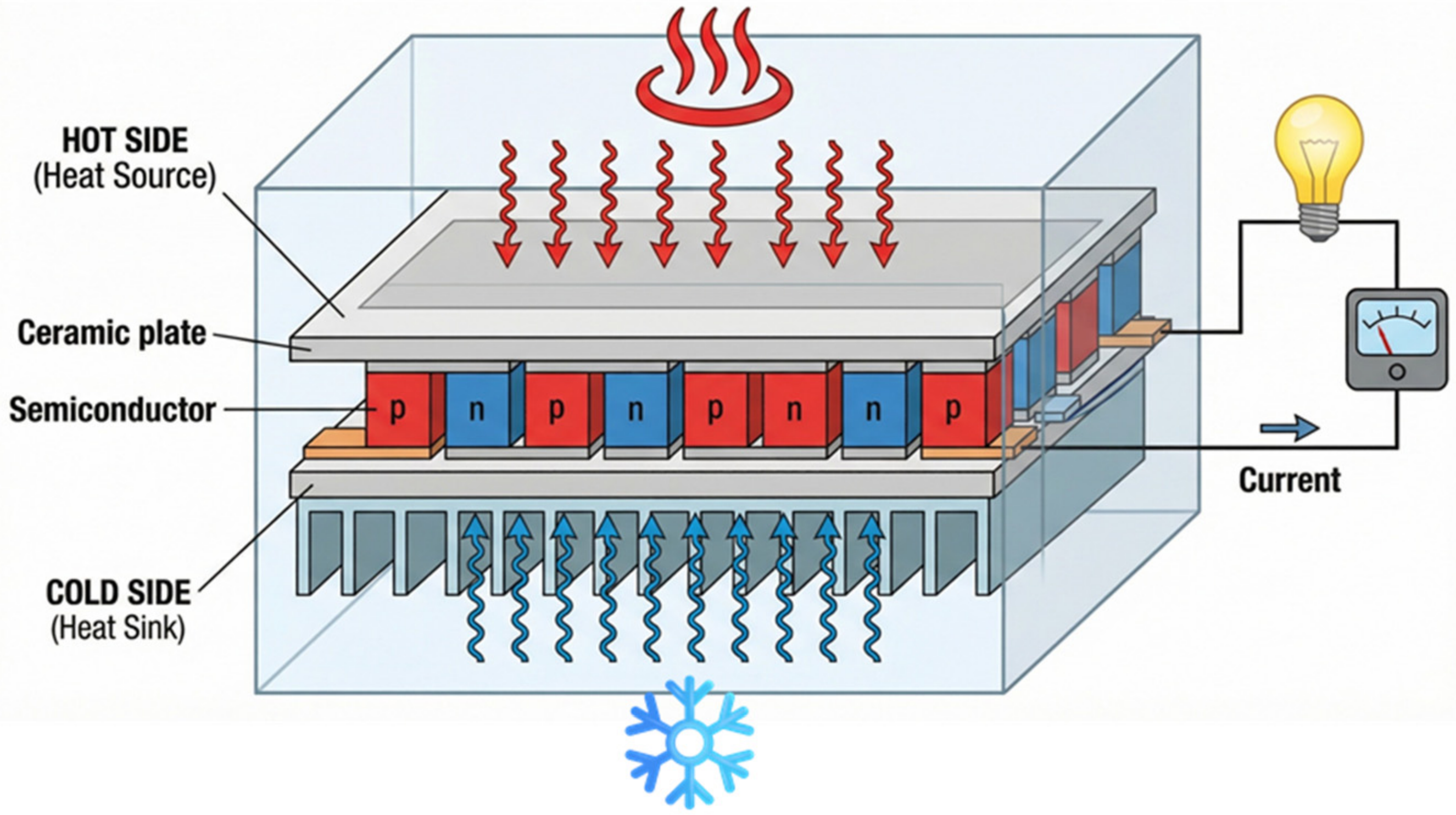
Among the various ambient sources, thermal energy harvesting using thermoelectric generators (TEGs) is especially attractive due to the widespread availability of waste heat in industrial processes, automotive systems, and even biological environments [24,25,26]. TEGs operate as solid-state devices with no moving parts, providing high reliability and continuous energy generation whenever a temperature gradient is present [27,28]. Their operation is primarily governed by the Seebeck effect, whereby an electromotive force is generated across a material subjected to a temperature difference (∆T) [29]. Figure 1 illustrates that by electrically connecting p-type and n-type thermoelectric elements in series, a usable output voltage (VOUT) proportional to the temperature gradient (∆T) can be obtained, VOC = α × ∆T where VOC is the open-circuit voltage and α is the Seebeck coefficient.
Despite ongoing advances in thermoelectric materials [30], the practical deployment of TEG-based EH systems remain fundamentally constrained by the low VOUT they generate under modest temperature gradients (∆T). In many realistic scenarios, the open-circuit voltage of miniature TEGs is limited to only tens or a few hundred millivolts [31,32,33,34,35,36], which is far below the minimum operating voltage required by conventional CMOS circuits [33,34]. This voltage mismatch presents a major power management challenge, as it prevents the direct activation of standard electronic systems. To bridge this gap, a DC-DC boost converter is required to raise the harvested voltage to a usable level [32,35,37]. However, the boost converter itself requires a minimum supply voltage to initiate operation, leading to a well-known “cold-start” dilemma [38,39].
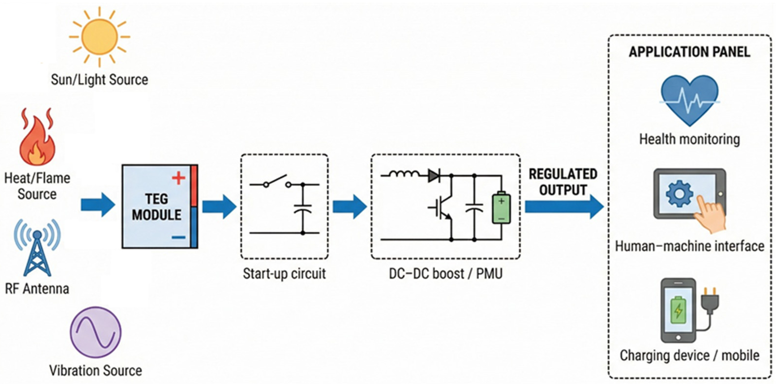
Figure 2 illustrates the block-level architecture of a TEG-based energy harvesting power management unit and places the start-up circuit within the complete PMU signal chain. During cold start, the TEG output voltage, VOUT, is insufficient to power the control circuitry of the main boost converter [40,41]. Therefore, a dedicated start-up circuit is required to accumulate energy from the ultra-low-voltage source and initiate the voltage-conversion process [35]. After the internal supply voltage reaches the required level, the main DC-DC boost converter takes over and transfers energy to the storage element. The complete PMU also requires auxiliary functional blocks, including an input/MPPT interface, voltage/reference generation circuits, control logic, protection and undervoltage-lockout circuits, and an output regulation/load-management stage. These output circuits are necessary to provide a stable regulated voltage to downstream loads such as IoT nodes, biomedical sensors, and portable electronics [17,37,42,43]. As a result, the start-up circuit is a critical but not standalone component of a complete TEG power-management system [44].
Over the past two decades, a wide range of start-up circuit topologies has been proposed to address this challenge, including battery-assisted approaches [45,46], transformer-based architectures [47,48], multi-source energy harvesting schemes [10,49], and fully integrated self-oscillating solutions [50,51,52]. While several review papers have discussed EH systems and power management units at a high level [50,53,54], a focused, topology-oriented analysis of start-up circuits specifically targeting sub-100 mV TEG operation remains limited. This gap is significant, as different start-up strategies exhibit fundamentally different trade-offs in terms of achievable start-up voltage, integration level, efficiency, and system complexity [55,56].
To address this need, this paper presents a design-oriented architectural review of ultra-low-voltage start-up circuits for TEG-based EH systems. Reported approaches are unified within a consistent classification framework and comparatively analyzed based on key performance metrics and practical design constraints [57,58,59]. By synthesizing recent advances and highlighting unresolved challenges, this review aims to provide a practical reference for circuit designers developing next-generation autonomous EH platforms.
Unlike prior reviews that focus broadly on energy harvesting systems or power management units, this work provides a design-oriented architectural perspective specifically targeting ultra-low-voltage start-up circuits for thermoelectric energy harvesting. By unifying disparate approaches under a consistent classification framework and emphasizing the feasibility of integration, autonomy, and circuit-level trade-offs, this review provides practical guidance for selecting start-up architectures in emerging self-powered systems.
The remainder of this paper is organized as follows. Section 2 reviews and classifies existing start-up circuit topologies based on their operating principles. Section 3 presents a comparative analysis and a topology selection guide to assist design decisions under ultra-low-voltage constraints. Section 4 discusses fundamental limitations, including subthreshold operation constraints, and outlines future research directions. Finally, Section 5 concludes the paper.

2. Start-Up Circuits Techniques

In typical EH applications, the system often begins in a fully depleted state, necessitating a dedicated cold-start block to initiate operation without relying on pre-charged external storage elements such as batteries or capacitors [60,61,62]. This start-up block must bootstrap the system using only TEG’s inherently low and often insufficient VIN (TEG terminal voltage). The primary design objective for this circuit is to minimize the start-up voltage (Vstart), as this metric directly determines the minimum temperature gradient from which the system can autonomously begin harvesting [63,64]. Consequently, secondary parameters such as power conversion efficiency and charging rate are often traded off to achieve the lowest possible Vstart.
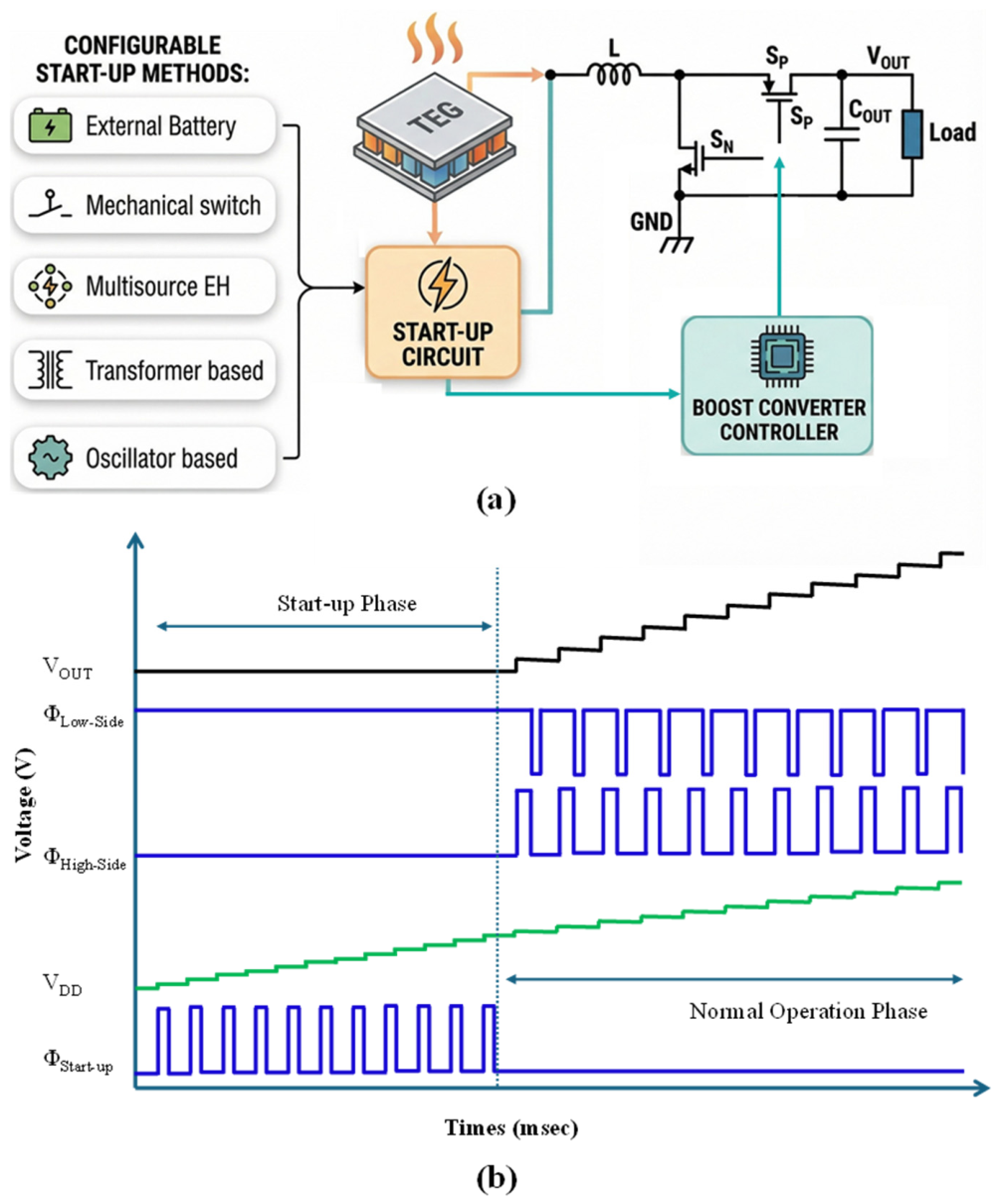
This operating paradigm is illustrated in Figure 3, which depicts a standard boost converter and its accompanying start-up circuit block. The design of this start-up block is the core differentiator among reported approaches, which can be broadly classified into external assistance (e.g., battery) [65], passive component-assisted techniques (e.g., mechanical switch, transformer) [66,67], multi-source harvesting [68,69], and fully integrated active circuits (e.g., oscillator-driven) [70,71]. Such converters typically require an initial internal supply of ≈500 mV (or higher, depending on process and controller design) to power their control circuitry before normal switching operation can begin. An auxiliary start-up circuit provides this critical initial energy pulse. The system-level benefit is significant: since the main converter can often operate steadily from input well below 100 mV, a low Vstart circuit enables harvesting from minimal thermal gradients [72,73]. Once the system is successfully bootstrapped, the start-up block is disabled to eliminate quiescent power drain, thereby maximizing steady-state efficiency.
Figure 3b illustrates the operational waveform during the start-up and normal operation phases. During the start-up, the TEG’s input voltage (VIN) activates the start-up circuit, which generates a pulse train (ΦStart-up). During the high phase of ΦStart-up, the VIN charges the boost converter inductor (L). During the low phase of ΦStart-up, the energy stored in L is transferred to the internal supply reservoir capacitor (CDD), which progressively raises the internal supply voltage (VDD) until the main converter becomes operational.
For a pulse width ton, the inductor current during the high phase can be approximated as
I L t o n = V IN L × t o n
The energy stored in the inductor is
E L = 1 2 L I L 2
E L = 1 2 L ( V I N L t o n ) 2 = V I N 2 t o n 2 2 L
Assuming this energy is delivered to the reservoir CDD, the incremental rise in VDD can be expressed as
V D D = E L C D D V D D V I N 2 t o n 2 2 L C D D V D D
With repeated pulses, VDD ramps upward until it crosses the controller’s enable threshold. The system then transitions to normal operation, where the controller generates complementary gate signals for the high-side (ΦHigh-side) and low-side (ΦLow-side) switches. Under regulated switching, the output voltage (VOUT) rises toward its steady-state target, completing autonomous initialization.

2.1. External Battery Assistance

A foundational, though ultimately limiting, start-up strategy involves the use of an external energy source, such as a battery [74,75] or a pre-charged capacitor [76]. While conceptually straightforward, this method introduces significant system-level drawbacks. It necessitates diverting a portion of harvested energy to replenish the auxiliary storage for subsequent start-up cycles, reducing the net energy delivered to the load. More critically, if the storage element is fully depleted, the system cannot self-recover, thereby violating energy autonomy, an unacceptable condition for remote sensing and biomedical implants where maintenance is impractical.
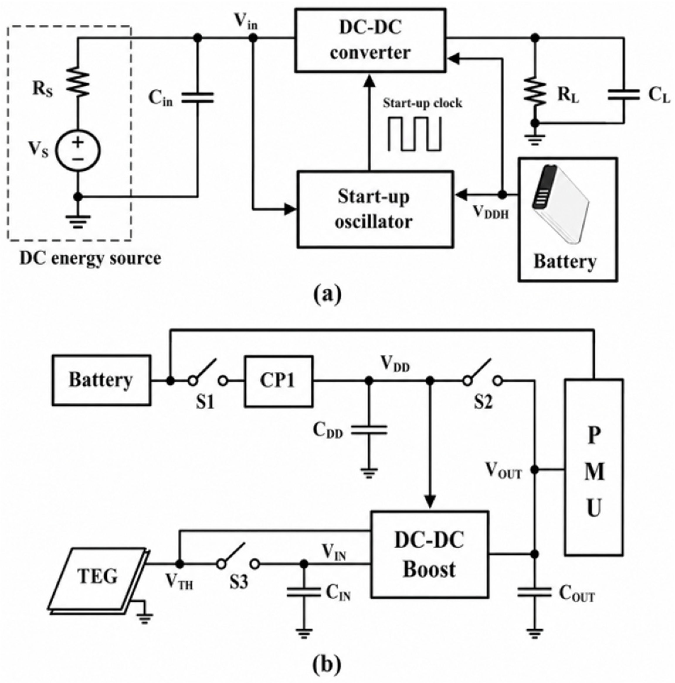
Representative system architectures for battery-assisted start-up are illustrated in Figure 4a,b [74,75]. In Figure 4a, the battery provides a high supply rail (VDDH) that directly powers both the start-up oscillator and the main converter control circuitry, ensuring reliable initialization even in the absence of sufficient EH. In Figure 4b, the battery biases a charge pump or auxiliary block to enable low-voltage operation while also supplying the PMU. Both configurations overcome the initial energy barrier, but they differ in how the auxiliary supply is integrated into the control and start-up path.
To mitigate these limitations, battery-assisted EH has been explored as a hybrid approach [77,78], where the energy harvester extends the service life of a rechargeable battery [79,80]. While this improves lifetime relative to purely battery-powered systems, it does not resolve the fundamental dependence on a component with a finite cycle life. The eventual need for replacement means such systems fall short of the goal of a truly maintenance-free platform.

2.2. Mechanical Switch-Assisted Start-Up

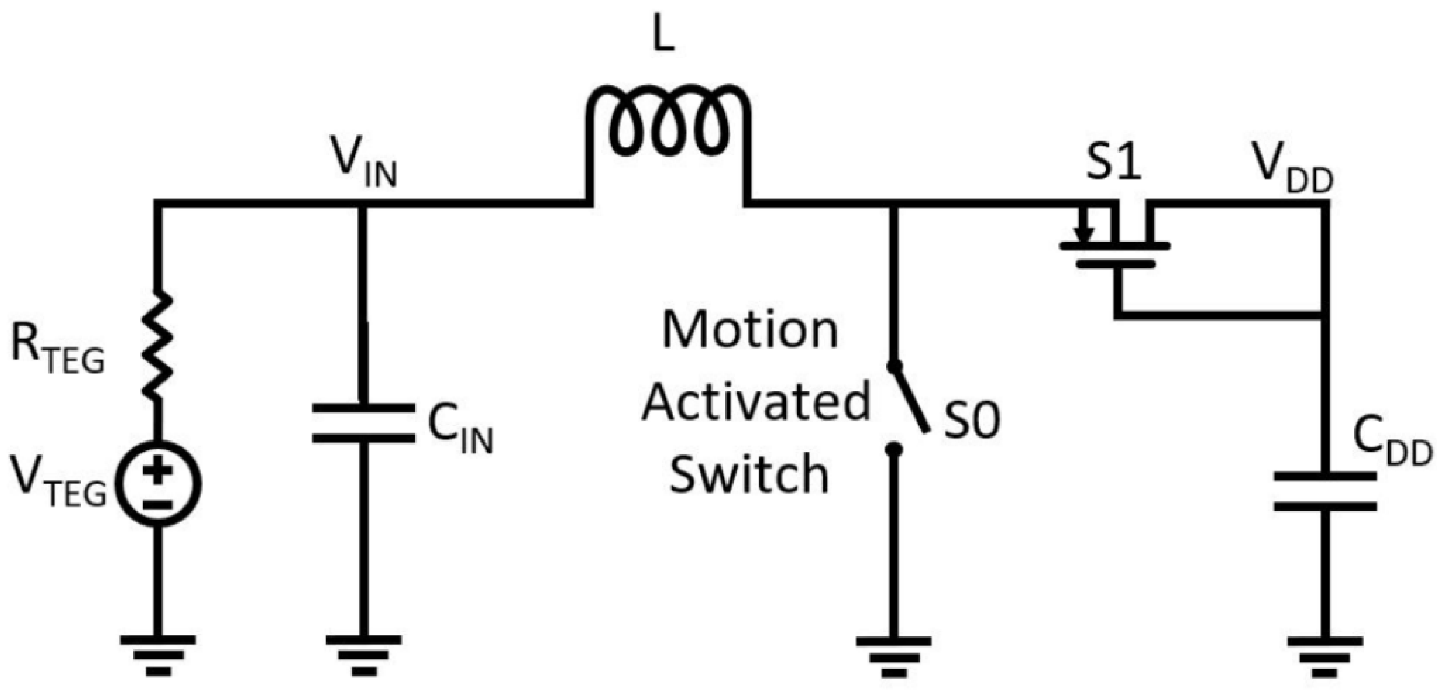
A distinct strategy, especially relevant to wearable applications, leverages kinetic energy from ambient body motion to actuate a mechanical switch [81,82]. As illustrated in Figure 5, vibrations from activities such as walking can trigger a mechanical switch (S0) (reported acceleration thresholds can be <100 mg), initiating a multi-step energy accumulation process. The operating principle follows a two-phase cycle: first, closure of S0 enables the TEG voltage to build current in an inductor; subsequently, opening of the switch forces this inductor current to charge a capacitor through an ideal diode switch (S1). Once the capacitor reaches sufficient voltage, it triggers a transient series RLC energy transfer that delivers the initial pulse required to bootstrap the main converter.
The main advantage of this method is that it achieves a remarkably low Vstart of ≈35 mV with a relatively simple circuit [66]. However, it imposes important practical constraints: it often requires a large inductance and a small capacitance, leading to bulky passive components and a limited power delivery capability. More critically, system operation depends on intermittent and unpredictable motion [83], making start-up timing variable and energy transfer potentially inefficient. These limitations restrict suitability for applications requiring reliable and repeatable cold-start behavior.

2.3. Multi-Source Energy Harvesting

A prominent strategy to overcome the cold-start problem is multi-source EH, which uses an auxiliary ambient energy source to bootstrap the system [84,85]. This approach can circumvent the voltage limitations of a single TEG. For instance, some solutions leverage RF energy via an antenna to harvest sufficient power to initiate the main TEG boost converter [9,86]. A more integrated hybrid thermal/RF architecture combines energy from both sources (often via rectification and power-combining) and can achieve operation from TEG inputs on the order of ≈50 mV [87,88]. Other co-design strategies exploit cross-source synergy; for instance, one approach uses the TEG’s DC voltage to bias a device in the RF rectifier path to improve RF-to-DC conversion efficiency [89].
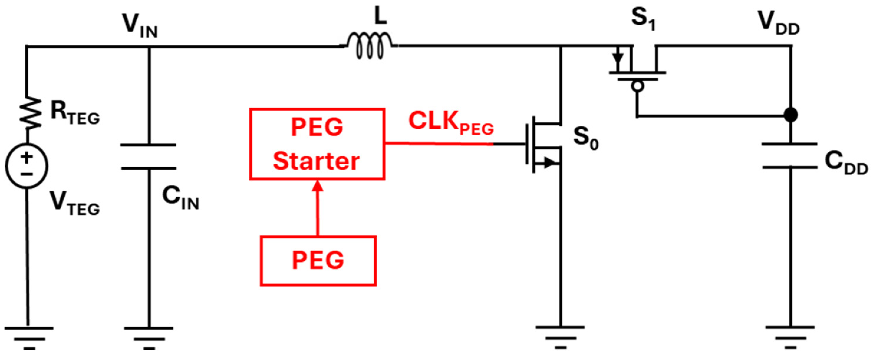
However, even “tens of millivolts” can exceed the ~10 mV available from compact TEGs under minimal ∆T. To bridge this gap, a hybrid TEG and piezoelectric generator (PEG) architecture has been proposed [68], as shown in Figure 6. In this design, the PEG harvests kinetic energy to generate a start-up clock signal (CLK_PEG), which drives the boost converter so that thermal energy can be accumulated on a storage capacitor even when VIN is extremely small.
A fundamental limitation shared by all multi-source approaches is increased system complexity, cost, and form factor. Additional transducers (antennas, piezoelectric elements), dedicated harvesting circuits, and sometimes off-chip components can reduce their suitability for miniaturized, single-primary-source applications.

2.4. Transformer-Based Techniques

Transformer-based start-up circuits form a distinct category that leverages the voltage gain of magnetically coupled inductors to achieve exceptionally low start-up voltages [45,90]. This makes them attractive in industrial applications where minimizing required input voltage can take precedence over miniaturization. Off-chip transformer implementations have demonstrated start-up from inputs as low as ≈20–30 [91,92,93], with the threshold often tunable via transformer turns ratio. Enhanced versions that incorporate voltage monitoring can further optimize and handover behavior.
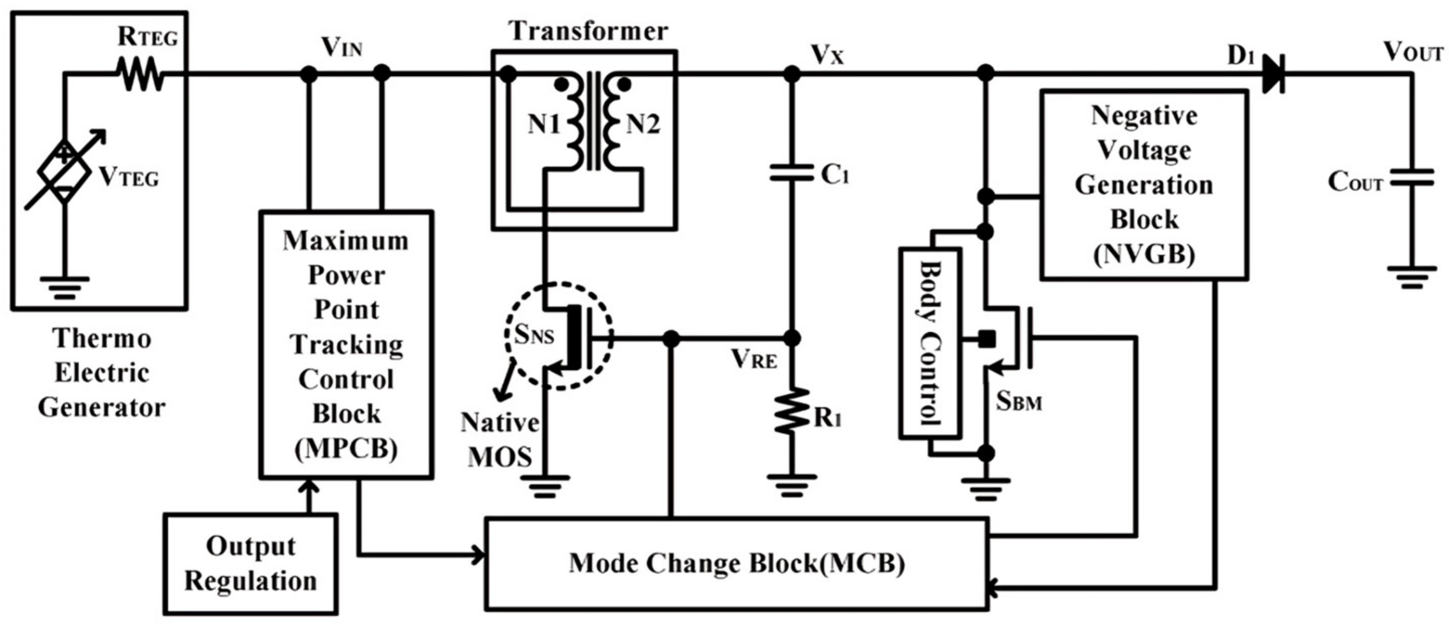
Specific implementations highlight inherent design compromises. For instance, one design achieves start-up from ≈40 mV and reuses a transformer winding as the main converter’s inductor, improving component utilization [67] as shown in Figure 7. However, such architecture can suffer from low conversion efficiency at VIN < 100 mV and introduce integration penalties.
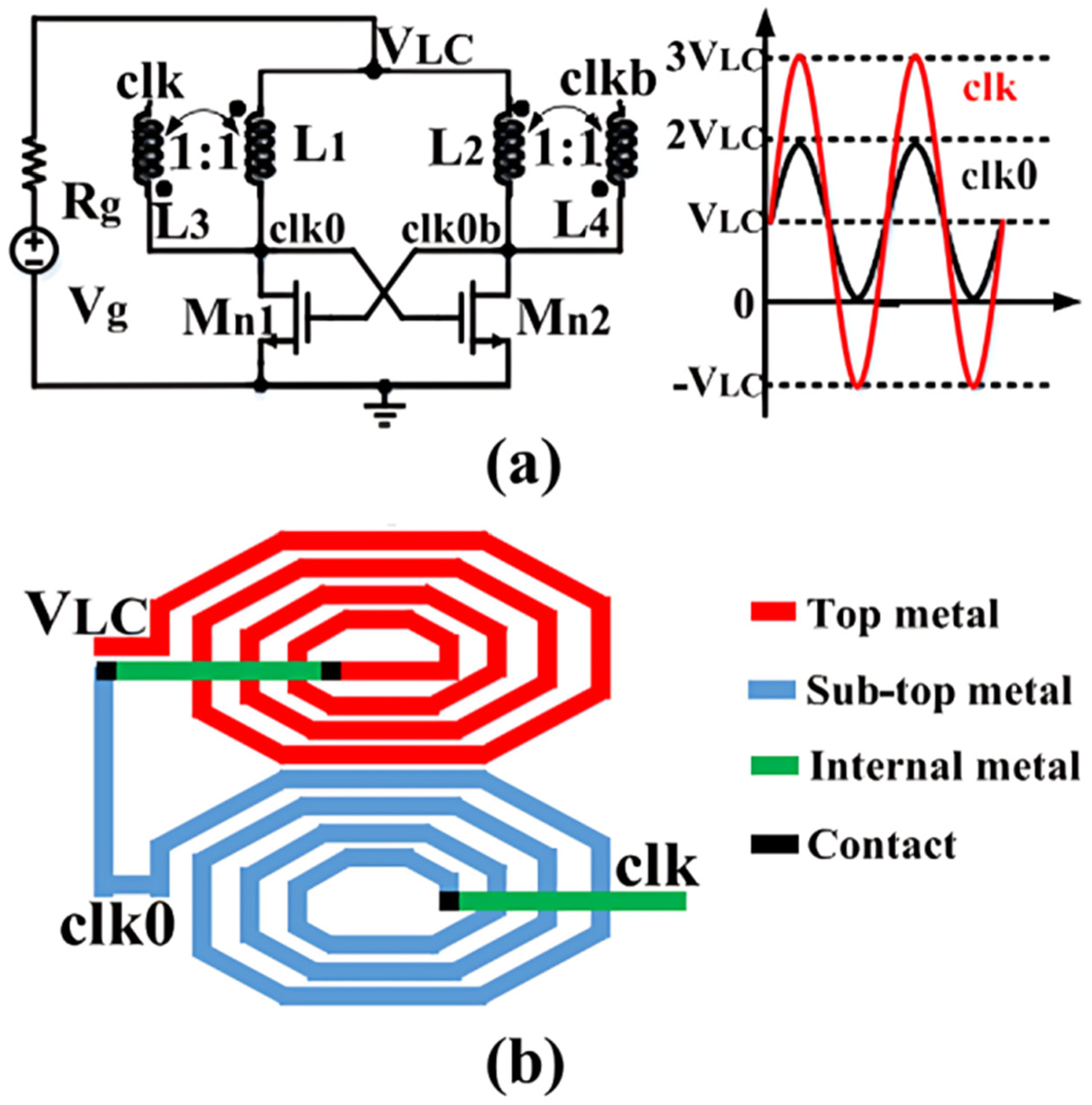
A key limitation of high-performance transformer-based solutions is reliance on large off-chip transformers, which prevents adoption in highly integrated systems [94,95]. As illustrated in Figure 8, on-chip transformers have been explored to improve integration; however, their performance is constrained by a low-quality factor (Q). For example, stacked-type transformer-based LC oscillators have reported start-up voltages around 100–160 mV and relatively low efficiencies [96]. Similarly, fully integrated voltage multipliers using on-chip transformers for passive clock boosting have reported start-up requirements on the order of ≈85 mV [97].
Despite the low Vstart capability of off-chip transformers, their dependency on external magnetics and the performance penalties of fully integrated transformer variants render this category less practical for compact TEG applications. This is particularly relevant because compact TEGs often generate only ≈40–60 mV under a small ∆T of 1–2K [98,99], a regime where integrated transformer-based solutions struggle to achieve competitive efficiency.

2.5. Oscillator-Based Techniques

Oscillator-based start-up circuits represent the final category in this review and are widely regarded as a promising path for ultra-low-voltage TEG EH due to their compatibility with standard CMOS processes and potential for monolithic integration. The core principle is to convert the low TEG DC voltage into an AC signal using an oscillator, then rectify and multiply it (e.g., via charge pump) to generate a voltage sufficient to bootstrap the main PMU [100,101,102]. Oscillators used in such systems are commonly grouped into resonant oscillators or waveform oscillators, each with distinct characteristics [103].
Resonant oscillators (e.g., LC-tank configurations) can offer a strong start-up performance. Reported examples include start-up from ≈50 mV using an LC oscillator with a voltage multiplier [104,105] and cold-start capability range of ≈60–200 mV using a Hartley oscillator that shares an inductor with the boost converter to reduce component count [106]. The most aggressive demonstrations report operation across a range of approximately 11–50 mV using enhanced-swing oscillator approaches with specialized devices and an off-chip inductor [107,108,109]. However, these approaches fundamentally depend on inductive components. While off-chip inductors can enable superior performance, they compromise integration; conversely, on-chip inductors suffer from low Q and large area values, limiting efficiency and practicality.
Waveform oscillators, particularly ring oscillators (ROs), present a more integration-friendly alternative due to their compact, transistor-only implementation, making them attractive for IoT nodes with strict area and cost constraints [64,110]. Conventional RO designs typically require several-hundred millivolts for robust switching, far exceeding the tens of millivolts available from TEGs under small ∆T [111,112]. This limitation has motivated gain-enhancement strategies (specialized delay cell, adaptive biasing, body-bias techniques) to maintain oscillation stability at ultra-low supply voltages.
Overall, oscillator-based start-up circuits establish a clear trajectory: resonant oscillators can achieve very low Vstart but face a fundamental integration barrier due to inductors, whereas ROs offer superior scalability and miniaturization at the cost of challenging millivolt-level design. Ongoing research continues to address these challenges through advanced delay cell architectures and biasing schemes, positioning ROs as one of the most practical solutions for next-generation autonomous systems.

2.5.1. Conventional Ring Oscillator

ROs have emerged as a leading option for integrated start-up clock generation primarily because they can be implemented using transistors alone, enabling compact area and low cost [73,113,114]. Unlike resonant oscillators that require inductive components, ROs are fully CMOS compatible and therefore well suited to miniaturized applications [115].
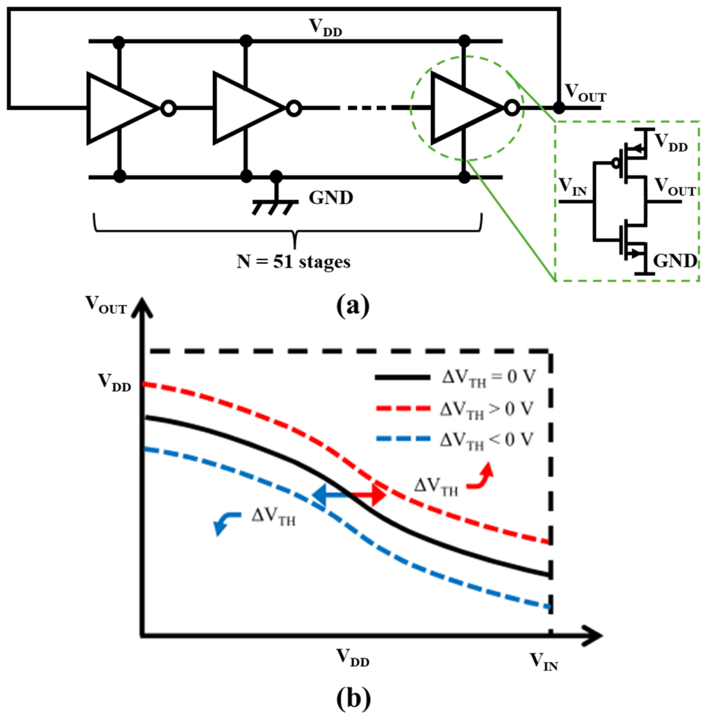
A conventional RO, shown in Figure 9a, consists of an odd number of inverter stages connected in a closed loop. Its oscillation frequency is determined directly by the number of stages and propagation delay, enabling straightforward design control [116]. Sustained oscillation requires the magnitude of inverter voltage gain to satisfy:
A I N V 1
Figure 9b illustrates a voltage transfer characteristic (VTC) under ultra-low supply voltages, VDD < VTH, where both transistors operate in a subthreshold regime. The drain current can be approximated as
I D = I 0 e x p ( V G S V T H η V T ) [ 1 e x p ( V D S V T ) ]
where I 0 = μ C O X W L V T 2 represents the pre-exponential factor; V T = k B T q is the thermal voltage. The inverter’s switching voltage is derived from current matching IN = IP, yielding:
V I N = V D D + V T H , N + V T H , P 2 + η V T 2 l n ( I 0 P I 0 N 1 e x p ( V O U T / V T ) 1 e x p ( V D D V O U T ) / V T )
Differentiating Equation (3) provides the inverter voltage gain A I N V = 2 e x p ( V O U T / V T ) [ 1 e x p ( V D D V O U T V T ) ] 2 η V T [ 1 e x p ( V D D V T ) ] . The maximum gain occurs at VOUT = VDD/2:
A I N V , M A X = V D D η V T e x p ( V D D 2 V T ) .
As Equation (8) clearly demonstrates, the maximum achievable gain decreases exponentially with reducing supply voltage, revealing the fundamental challenge of implementing ROs in ultra-low-voltage EH systems. Equation (7) indicates significant sensitivity to threshold voltage mismatch ∆VTH = |VTH,NVTH,P|, which shifts the VTC horizontally and degrades the effective gain.
As the supply decreases into deep subthreshold, the available inverter gain decreases rapidly, making the loop-gain criterion difficult to satisfy and limiting oscillation amplitude and frequency. Conventional gain-compensation strategies (more stages, wider devices) increase leakage and static power and enlarge area, undermining RO advantages [117,118]. Therefore, the RO-based start-up circuit must balance minimum operating voltage, sufficient oscillation swing, and acceptable overhead under process/voltage/temperature variation.

2.5.2. Ring Oscillator Using Self-Biased Inverter

Conventional CMOS inverters typically require supply voltages far above those available from miniature TEGs. Operating standard inverters at ultra-low voltages degrades the on/off ratio and stage gain, compromising oscillation reliability [119].
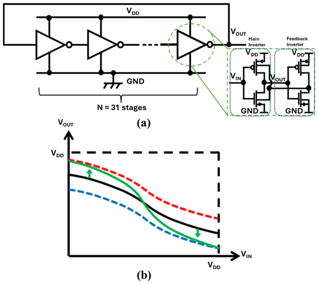
To address this limitation, a self-biased inverter (SBI) delay cell has been proposed as a gain-enhanced stage [116]. As illustrated in Figure 10a, the SBI architecture introduces feedback that dynamically adjusts the body bias, effectively modulating threshold voltage (VTH):
V T H = V T H 0 + γ ( 2 ϕ F V B S 2 ϕ F ) ,
where VBS is the body-source voltage, VTH0 is the threshold voltage at VBS = 0 V, γ is the proportional factor, and ϕF is the surface potential.
This dynamic biasing sharpens the VTC and increases stage gain, enabling oscillation at significantly lower supply voltages as shown in Figure 10b. SBI-based ROs have reported oscillation down to ≈42 mV, improving suitability for TEG systems [116]. While this reduces the number of stages required compared to conventional inverters, it adds design complexity and can increase overhead due to auxiliary circuitry.

2.5.3. Ring Oscillator Using Stacked Three-Inverter Delay Cell

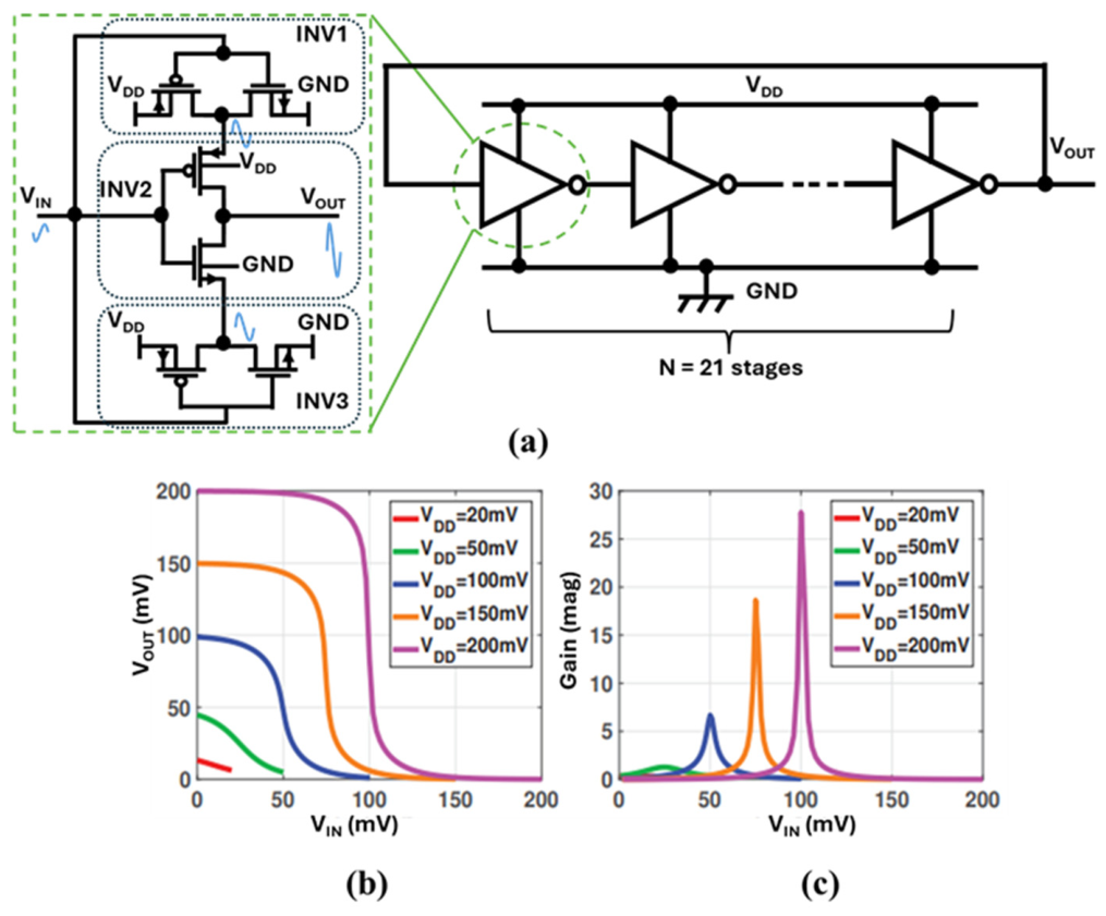
At very low supplies, RO performance is limited by degraded inverter gain and reduced output voltage swing [119]. To mitigate these limitations, a stacked three-inverter delay cell has been proposed, demonstrating self-sustained oscillation from ≈50 mV [112]. As shown in Figure 11a, the three inverters (INV1, INV2, INV3) are arranged such that the input drives all gates, while a regenerative path improves effective switching behavior and supports higher swing. Proper DC operating point is maintained by device sizing (e.g., sizing the outer device larger than the inner devices) [120].
Figure 11b illustrates inverter VTC degradation as VDD decreases; the transition region flattens as gain falls. This behavior is consistent with the widely cited discussion of the “thermal limit” discussion: CMOS inverter switching under ideal subthreshold assumptions at 300 K is often associated with a characteristic voltage scale near ≈36 mV [121]. Importantly, this should be interpreted as a practical lower bound under idealized assumptions, not a strict impossibility, and real circuits may deviate depending on device selection, leakage, and operating conditions [122].
Fabricated in 180 nm CMOS, a 21-stage RO using this cell reported kHz-level oscillation with high swing at tens of millivolts supply [112]. The trade-off is increased area and power due to the higher transistor count and routing complexity per stage. Nonetheless, this approach is valuable where the minimum operating voltage is the dominant constraint.

2.5.4. Ring Oscillator Using Tri-State Buffer

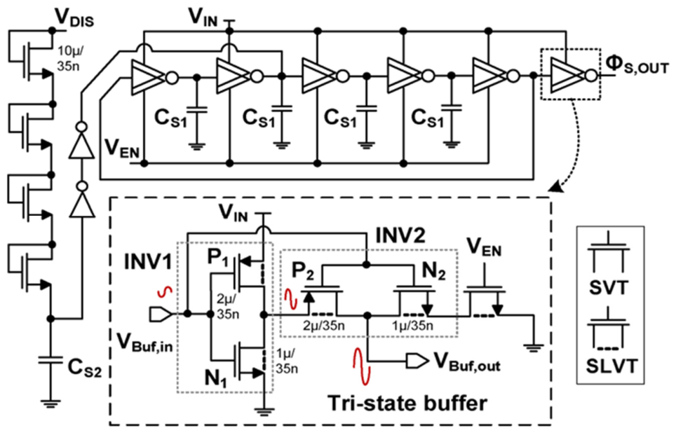
At TEG-level supplies, conventional ROs are limited by reduced stage gain and reduced output swing, which can impair the ability to drive subsequent stages [119]. A gain-enhanced RO architecture incorporating a tri-state buffer has been introduced to improve effective transconductance and stage gain [123]. As shown in Figure 12, a primary inverter (INV1) drives a tri-state buffer stage (INV2). Use of super low-threshold voltage (SLVT) devices can further lower operating voltage, while tri-state behavior improves signal shaping and propagation.
A common analytical view expresses the inverter gain as:
A V 1 g m , e f f 1 g d s , N 1 + g d s , P 1 = g m , N 1 + g m , P 1 g d s , N 1 + g d s , P 1 ,
where the effective transconductance gm,eff1 is the transconductance sum of N1 and P1. The gds, N1, and gds, P1 are the output conductance of N1 and P1, respectively. The effective transconductance enhancement in the tri-state buffer can be approximated by:
g m , eff 2 1 + A V 1 g m , P 2 + g m , N 2
where gm,P2 and gm,N2 are the transconductance of P2 and N2, respectively. The resulting stage gain is:
A V 2 g m , e f f 2 g d s , P 2 + g d s , N 2 = 1 + A V 1 g m , P 2 + g m , N 2 g d s , P 2 + g d s , N 2
where gds,N2 and gds,P2 are the output conductance of N2 and P2, respectively.
This architecture can provide stronger gain and output swing at low supply, but at the expense of increased transistor count and potential overhead due to device choices and additional circuitry. It is most suitable for scenarios where guaranteed cold-start performance justifies higher resource utilization.
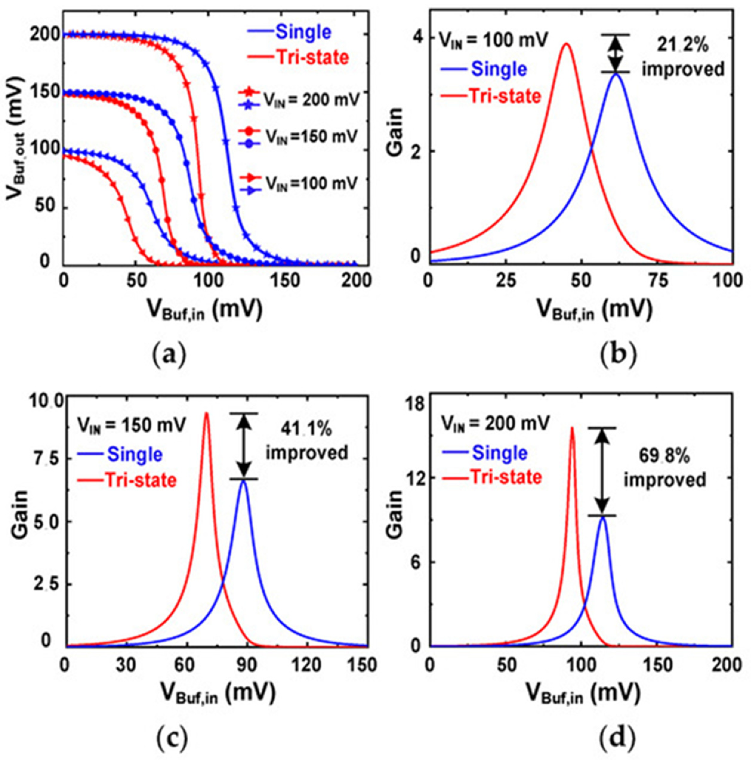
Figure 13a compares the voltage transfer characteristics of a single-stage buffer and tri-state buffers at three VIN values. The tri-state buffer exhibits steeper slopes, indicating higher gain. The gain enhancement is further quantified in Figure 13b–d. At VIN = 100 mV, a gain improvement of approximately 21.2% has been reported, increasing to 41.1% at 150 mV and 69.8% at 200 mV [123]. These results support the tri-state buffer as an effective gain-enhancement approach for ultra-low-voltage start-up circuits.

3. Performance Comparison

Building on the system-level motivation introduced in Section 1 and the taxonomy of start-up techniques reviewed in Section 2, this section consolidates the taxonomy introduced in Section 2 and provides a comparative interpretation across three levels: (a) category-level trade-offs (Table 1), (b) topology-level trade-offs within RO start-up circuits (Table 2), and (c) benchmarking of representative reported implementations (Table 3).

3.1. Cross-Category Comparison of Start-Up Strategies (Table 1)

Table 1 compares five major classes of start-up techniques for ultra-low-voltage TEG-EH systems, highlighting their implications for start-up voltage, integration level, autonomy, and cost. From an energy-conversion perspective, the key observation is that minimizing start-up voltage alone is insufficient; practical deployment additionally requires scalability, long-term autonomy, and compatibility with compact system architectures.
Battery-assisted start-up schemes provide highly reliable initialization by externally supplying the required control bias. However, they fundamentally undermine the objective of energy autonomy and introduce maintenance, replacement, and environmental concerns, which are incompatible with long-term, maintenance-free operation. Mechanical switch-assisted techniques can achieve very low apparent start-up voltages by externally triggering energy transfer, but their dependence on intermittent mechanical excitation and bulky passive components limits repeatability and robustness, particularly in unattended or implantable systems.
Multi-source energy harvesting approaches reduce the effective cold-start barrier by supplementing thermal energy with auxiliary sources such as RF or kinetic energy. While this improves start-up robustness under weak temperature gradients, it increases system complexity, transducer count, and cost, which can negate the benefits of single-source TEG solutions. Transformer-based start-up architectures achieve some of the lowest reported start-up voltages due to magnetic voltage gain, but their reliance on off-chip magnetics constrains miniaturization and prevents full system-on-chip (SoC) integration.
In contrast, oscillator-based start-up techniques provide the most direct pathway to fully integrated, CMOS-compatible implementations. Although their achievable start-up voltage is typically higher than that of transformer-based or mechanically assisted schemes, they preserve autonomy, reduce form factors, and enable scalable manufacturing. Table 1 therefore reveals a fundamental trade-off: as start-up architectures evolve toward full integration and autonomy, the achievable start-up voltage becomes increasingly governed by circuit-level gain generation and loss mechanisms rather than external voltage amplification.

3.2. Comparison of RO Start-Up Topology (Table 2)

Table 2 compares RO delay-cell topologies that enable integrated cold-start operation under deep-subthreshold conditions. Because oscillator-based architecture offers the highest level of CMOS compatibility among start-up techniques, the comparison focuses on how different RO designs address-gain degradation and voltage swing limitations at ultra-low supply voltages.
Conventional inverter-based ROs offer minimal area and design simplicity; however, their insufficient small-signal gain and degraded voltage transfer characteristics severely limit operation below 50 mV. To address this limitation, gain-enhanced RO variants employ architectural techniques that improve effective transconductance at low supply voltages. Self-biased inverter ROs dynamically modulate device thresholds to enhance switching behavior, achieving reduced start-up voltage with moderate overhead. Stacked three-inverter delay cells introduce regenerative feedback paths that support oscillation near the practical low-voltage boundary, albeit at the cost of increased transistor count and routing complexity. Tri-state buffer-based ROs further enhance effective gain through bootstrapping, providing a strong output swing and improved robustness when driving rectification and charge-pump stages, although they typically require additional circuitry and low-threshold devices.
From an energy-conversion perspective, Table 2 highlights that RO-based cold-start operation is fundamentally governed by the trade-off between effective gain generation and parasitic loss under extreme current constraints. Achieving lower start-up voltage generally necessitates increased architectural complexity, underscoring the need for careful co-optimization of area, leakage, and robustness to process, voltage, and temperature (PVT) variation in fully integrated TEG energy harvesting systems.

3.3. Benchmarking of Reported Start-Up Implementations (Table 3)

Table 3 benchmarks representative reported start-up implementations across the architectural spectrum. A clear pattern emerges: the lowest start-up voltages are typically achieved using external components such as batteries, mechanical switches, off-chip transformers, or auxiliary harvesters. While effective from a voltage standpoint, these solutions incur penalties in system size, cost, and integration suitability, limiting their relevance for compact TEG-powered devices.
Among fully integrated solutions, a performance gradient is observed. Charge-pump-based start-up circuits typically require higher input voltages but offer simplicity and ease of integration. On-chip transformers or LC-based approaches reduce the start-up threshold but remain constrained by low-quality-factor magnetics and associated efficiency penalties. RO-based start-up circuits occupy the most practical region for monolithic systems, with reported start-up voltages typically in the tens of millivolts, depending on the chosen gain-enhancement strategy and device assumptions. These observations reinforce the conclusion that further reductions in start-up voltage within standard CMOS technologies will primarily rely on architectural innovation rather than incremental topology refinement.

3.4. Application Scenarios and Reported TEG Performance

The reviewed start-up circuits target different TEG operating environments, and their practical suitability depends strongly on the available temperature gradient, source impedance, form-factor constraint, and load profile. For wearable and biomedical platforms, the available thermal gradient is often only a few kelvin. Therefore, compact TEGs may produce input voltages in the tens of millivolts and power levels ranging from microwatts to low milliwatts. In this regime, body-heat harvesters and battery less sensor interfaces require cold-start thresholds below a range of approximately 35–70 mV together with very low quiescent control power [32,38,66,73]. For IoT sensor nodes placed near machinery, building surfaces, or industrial waste-heat sources, the thermal gradient can be more stable and higher, allowing start-up voltages near a range of 70–190 mV and enabling higher steady-state output power after the boost converter enters normal operation [32,37,56,57]. In automotive and battery thermal-management applications, the larger heat flux and physical volume can justify transformer-assisted or hybrid approaches because the priority may shift from full monolithic integration to high conversion efficiency and robust cold start [26,79,80].
Ultra-low-power electronic systems, such as wearable health-monitoring sensors, biomedical implants, wireless IoT sensor nodes, industrial condition-monitoring devices, automotive sensors, and battery thermal-management systems, are frequently powered by harvested thermoelectric energy. The target application has a significant impact on PMU design. Wearable and biological systems are typically subjected to modest and unstable temperature gradients, necessitating low start-up voltage, low leakage, compact size, and full integration. IoT sensor nodes frequently function intermittently, necessitating efficient energy storage, load gating, and regulated output delivery for sensing, computing, and wireless communication. Industrial and automotive systems may produce larger thermal gradients, but the PMU must handle larger input voltage variation, higher operating temperatures, and fluctuating heat sources.
From an application point of view, no single start-up circuit is usually ideal. Battery-assisted and mechanically aided circuits are appropriate when consistent triggering is more critical than maintenance-free autonomy. Multi-source circuits are appealing when an additional ambient source, such as vibration, RF, or piezoelectric energy, is readily available. Transformer-based circuits are beneficial when the input voltage is extremely low and off-chip magnetics are permitted. Fully integrated oscillator-based circuits, particularly RO-based variations, are best suited to miniaturized wearable, implantable, and IoT devices where volume, cost, and CMOS compatibility are critical. Therefore, start-up topology selection should not be based only on the minimum start-up voltage. It must also consider output-power demand, storage capacity, load profile, form factor, reliability, and whether off-chip components are acceptable. This application-oriented interpretation complements the topology-oriented comparison in Table 1, Table 2 and Table 3 and clarifies how reported TEG performance should be matched to the intended deployment scenario.

3.5. Topology Selection Guide for TEG Start-Up Design

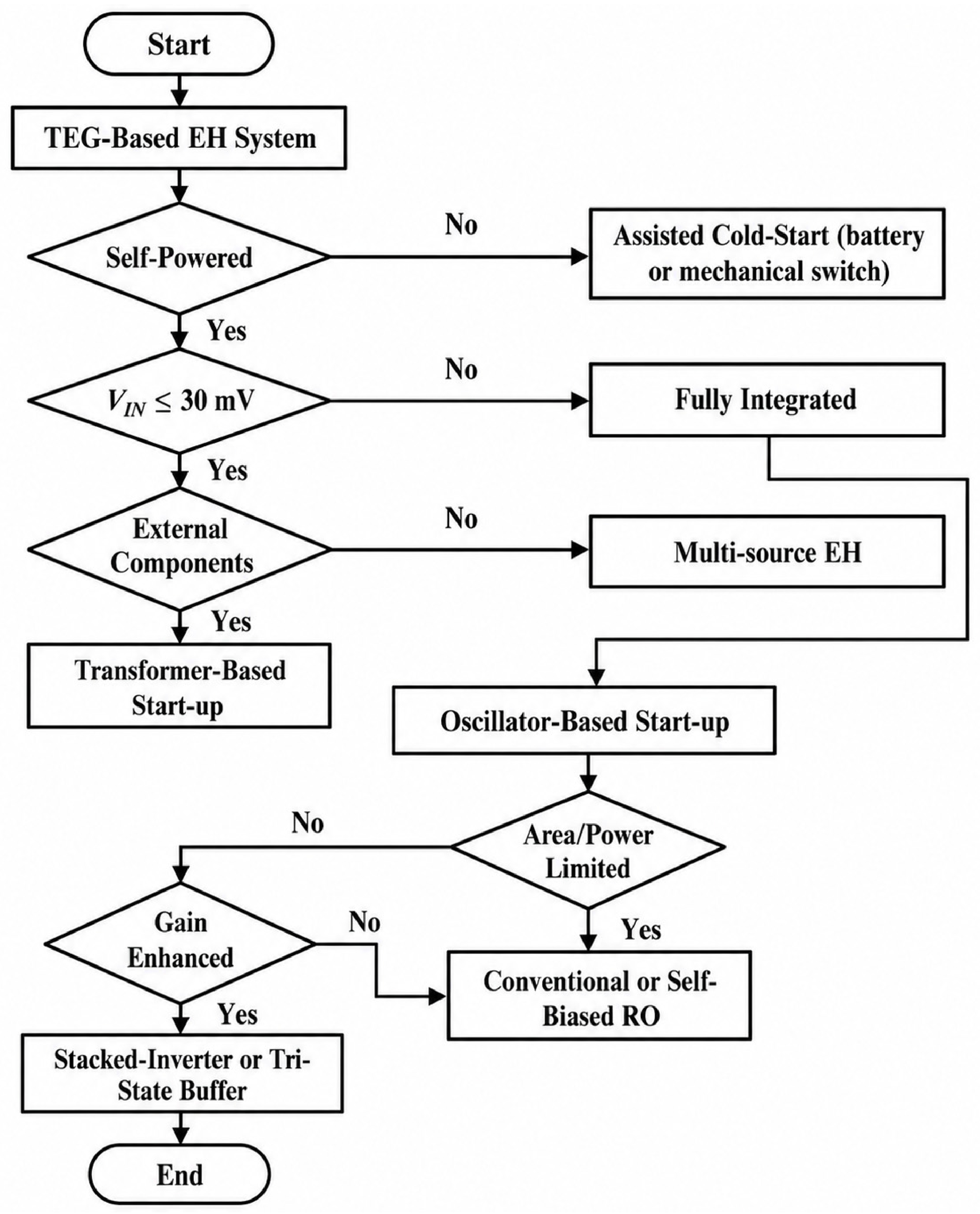
To consolidate the insights from Table 1, Table 2 and Table 3, Figure 14 presents a topology selection guide for ultra-low-voltage start-up circuits in TEG-EH systems. The guide first distinguishes whether a true self-powered cold-start operation is required. If external assistance is acceptable, battery- or mechanically assisted solutions provide robust initialization but compromise autonomy or determinism. For fully self-powered systems, the selection depends on the available TEG input regime and the permissibility of external passive components. When full integration is required, oscillator-based start-up architectures emerge as the default choice, with RO topology selection guided by acceptable overhead, target start-up voltage, and robustness requirements. This guide is intended to support architecture-level decision-making for energy harvesting systems rather than circuit-level optimization alone.

4. Discussion and Future Directions

The design of start-up circuits for TEG-based energy harvesting has reached a point where reducing Vstart further involves clear practical trade-offs. Techniques based on transformers or mechanical switches have demonstrated impressively low start-up voltages, in some cases between 20 and 35 mV. However, these gains are achieved at the cost of bulky off-chip components, which makes such approaches difficult to scale for compact IoT and biomedical applications where size, cost, and integration are critical. For these reasons, RO-based architecture has emerged as a more realistic solution for fully autonomous and highly integrated systems. Their compatibility with standard CMOS processes enables compact, monolithic implementations that are well-suited for large-scale deployment. At the same time, RO-based designs face inherent limitations when operating deep in the subthreshold regime. As the supply voltage approaches the millivolt range, inverter gain and output swing degrade rapidly, reflecting the fundamental constraints of thermal carrier transport often referred to as the Boltzmann limit. This helps explain why reported RO start-up voltages in recent work tend to cluster in the range of 40–60 mV, suggesting that further reductions will be increasingly difficult to achieve through circuit topology alone.
In addition to lowering Vstart, ensuring reliable system behavior during the transition from cold start to normal operation remains a major challenge. If the main boost converter is enabled too early, the supply can collapse and force a repeated restart cycle; if enabled too late, valuable harvested energy is wasted. Addressing this balance requires more adaptive handover strategies that respond to the actual energy available in storage elements, rather than relying solely on fixed voltage thresholds. Looking ahead, meaningful progress in TEG-based EH is unlikely to come from isolated circuit optimizations in a single block. Instead, future advances will depend on coordinated design across devices, circuits, and system-level control, with careful attention to process, voltage, and temperature variations. Establishing common figures of merit that capture start-up capability, integration level, efficiency, and robustness would also help provide clearer benchmarks and a guide to the development of truly autonomous EH platforms.
A practical TEG source is rarely static. Because the temperature gradient, thermal contact resistance, heat-flow channel, and load state might change dynamically over time, the generated voltage and power fluctuate. For wearable TEGs, body motion and ambient airflow can alter the thermal gradient, whereas in industrial or automotive environments, waste heat may fluctuate with operating cycles. As a result, TEG power-management circuits must support time-adaptive operation. Adaptive techniques include dynamic maximum power point tracking, switching frequency adjustment, pulse-frequency modulation under light-load conditions, zero-current or zero-voltage switching control, adaptive undervoltage lockout, and controlled load connection only when sufficient stored energy is available. Time adaptivity is especially critical in cold-start circuits when transitioning from the start-up block to the main boost converter. If the main converter is turned on too soon, the internal supply may fail; if it is turned on too late, the captured energy is lost. As a result, future TEG PMUs should integrate low-voltage start-up capability with adaptive control that reacts to the instantaneous energy available from the TEG and storage element.
In addition to start-up voltage, the energy overhead of the power-management circuit is an important design consideration. Several PMU sub-blocks, including the oscillator, voltage detector, MPPT controller, gate drivers, reference generator, protection circuit, and output regulator, use energy during start-up and steady-state operations. For ultra-low-voltage TEG systems, the harvested power under tiny temperature gradients may be severely limited; thus, the PMU must consume significantly less power than the gathered source. Otherwise, a circuit may display cold-start capability while providing little or no net energy to the load. This trade-off is especially critical in oscillator-based start-up circuits, where decreasing the start-up voltage frequently necessitates additional gain-enhancement circuitry, body-biasing networks, or charge-pump stages. These blocks improve cold-start performance while potentially increasing leakage, area, and dynamic power. Thus, future comparisons should consider not only V_start and peak efficiency, but also start-up energy, quiescent current, control-circuit overhead, and the ratio of delivered load energy to harvested TEG energy.

5. Conclusions

This paper presented a design-oriented architectural review of start-up circuit techniques addressing the cold-start challenge in thermoelectric EH systems. Five major categories, external energy assistance, mechanical switch-assisted, multi-source harvesting, transformer-based, and oscillator-based architectures, were analyzed in terms of operating principles, integration feasibility, and practical limitations. The comparative analysis highlights a fundamental trade-off between achieving ultra-low start-up voltage and maintaining system autonomy, scalability, and monolithic integration. While external and passive-component-based approaches can demonstrate exceptionally low start-up voltages, they inherently compromise integration and long-term autonomy. In contrast, oscillator-based solutions, particularly advanced RO architectures employing gain-enhancement techniques, offer the most balanced pathway toward fully integrated, autonomous TEG-powered systems. Future progress is expected to rely on coordinated device-circuit-system co-design and standardized evaluation methodologies, rather than isolated reduction in start-up voltage alone.

Author Contributions

M.A.: Writing—original draft, conceptualization, and validation.; S.J.U.H.: Writing—review and editing.; S.C.: Writing—review and supervision. All authors have read and agreed to the published version of the manuscript.

Funding

This research was supported by the National Research Foundation of Korea (NRF-2023R1A2C1003669).

Data Availability Statement

Data will be made available on request.

Acknowledgments

The authors have reviewed and edited the output and take full responsibility for the content of this publication.

Conflicts of Interest

The authors declare no conflicts of interest.

Abbreviations

The following abbreviations are used in this manuscript:
TEGThermoelectric generator
EHEnergy harvesting
RORing oscillator
RFRadio frequency
VINInput voltage
VOUTOutput voltage
VstartStart-up voltage
VDDHHigh supply rail
VDDSupply rail
PMUPower management unit
PEGPiezoelectric generator
CLK_PEGStart-up clock signal
VTCVoltage transfer characteristic
AINVInverter voltage gain
SBISelf-biased inverter
VOCOpen circuit voltage

References

  1. Hao, D.; Qi, L.; Tairab, A.M.; Ahmed, A.; Azam, A.; Luo, D.; Pan, Y.; Zhang, Z.; Yan, J. Solar energy harvesting technologies for PV self-powered applications: A comprehensive review. Renew. Energy 2022, 188, 678–697. [Google Scholar] [CrossRef]
  2. Du, H.; Lu, J.; Zhang, W.; Yang, G.; Zhang, W.; Xu, Z.; Wang, H.; Dai, K.; Gao, L. Advancements and Future Prospects of Energy Harvesting Technology in Power Systems. Micromachines 2025, 16, 964. [Google Scholar] [CrossRef] [PubMed]
  3. Jaziri, N.; Boughamoura, A.; Müller, J.; Mezghani, B.; Tounsi, F.; Ismail, M. A comprehensive review of thermoelectric generators: Technologies and common applications. Energy Rep. 2020, 6, 264–287. [Google Scholar] [CrossRef]
  4. Nozariasbmarz, A.; Collins, H.; Dsouza, K.; Polash, M.H.H.; Hosseini, M.; Hyland, M.; Liu, J.; Malhotra, A.; Ortiz, F.M.; Mohaddes, F.; et al. Review of wearable thermoelectric energy harvesting: From body temperature to electronic systems. Appl. Energy 2020, 258, 114069. [Google Scholar] [CrossRef]
  5. Covaci, C.; Gontean, A. Piezoelectric energy harvesting solutions: A review. Sensors 2020, 20, 3512. [Google Scholar] [CrossRef] [PubMed]
  6. Chandrarathna, S.C.; Graham, S.A.; Ali, M.; Yu, J.S.; Lee, J. An efficient power management system using dynamically configured multiple triboelectric nanogenerators and dual-parameter maximum power point tracking. Adv. Energy Mater. 2022, 12, 2103249. [Google Scholar] [CrossRef]
  7. Jiang, J.; Liu, S.; Feng, L.; Zhao, D. A review of piezoelectric vibration energy harvesting with magnetic coupling based on different structural characteristics. Micromachines 2021, 12, 436. [Google Scholar] [CrossRef]
  8. Bzzou, M.; Karfa Bekali, Y.; El Bhiri, B. RF energy-harvesting systems: A systematic review of receiving antennas, matching circuits, and rectifiers. Eng. Proc. 2025, 112, 48. [Google Scholar] [CrossRef]
  9. Arinze, S.N.; Obi, E.R.; Ebenuwa, S.H.; Nwajana, A.O. RF energy-harvesting techniques: Applications, recent developments, challenges, and future opportunities. Telecom 2025, 6, 45. [Google Scholar] [CrossRef]
  10. Shi, X.; Cai, M.; Jiang, Y. Key role of cold-start circuits in low-power energy harvesting systems: A research review. J. Low Power Electron. Appl. 2024, 14, 55. [Google Scholar] [CrossRef]
  11. Ali, A.; Shaukat, H.; Bibi, S.; Altabey, W.A.; Noori, M.; Kouritem, S.A. Recent progress in energy harvesting systems for wearable technology. Energy Strategy Rev. 2023, 49, 101124. [Google Scholar] [CrossRef]
  12. Panatik, K.Z.; Kamardin, K.; Shariff, S.A.; Yuhaniz, S.S.; Ahmad, N.A.; Yusop, O.M.; Ismail, S. Energy harvesting in wireless sensor networks: A survey. In Proceedings of the 2016 IEEE 3rd International Symposium on Telecommunication Technologies (ISTT), Kuala Lumpur, Malaysia, 28–30 November 2016; pp. 53–58. [Google Scholar] [CrossRef]
  13. Reddy, M.N.; Sekhar, Y.C.; Sarma, L.S. Ni(OH)2/CeO2 heterointerface catalysts for energy-efficient urea electrooxidation. New J. Chem. 2025, 49, 19121–19132. [Google Scholar] [CrossRef]
  14. Sekhar, Y.C.; Vinothkumar, V.; Rao, H.S.; Cho, S.; Kim, T.H. Thermally treated MoO3 supports for Pt/C catalysts: Enhancing the methanol electro-oxidation efficiency. Adv. Mater. Technol. 2026, 11, 2501383. [Google Scholar] [CrossRef]
  15. Sekhar, Y.C.; Cho, S. Advances in methanol oxidation catalysts and system-level engineering for direct methanol fuel cells. Chem. Commun. 2026, 62, 7925–7942. [Google Scholar] [CrossRef] [PubMed]
  16. Prasad, K.; Sreekanth, T.V.M.; Kamakshi, S.; Cho, S.; Yoo, K.; Kim, J. Construction of CeO2@CoMoO4 hydrangea flower-like architectures: Insights into faradaic-dominated intercalation pseudocapacitance and high energy density supercapacitor using biomass-derived porous carbon anode. J. Energy Storage 2026, 153, 121015. [Google Scholar] [CrossRef]
  17. Hussain, B.; Ullah, A.; Ali, I.; Haider, S.; Han, H.J.; Jin, G. Advances in semiconductor materials and device architectures for biomedical systems: A mini review. Biomed. Eng. Lett. 2026, 16, 663–680. [Google Scholar] [CrossRef]
  18. Tao, X. Study of fiber-based wearable energy systems. Acc. Chem. Res. 2019, 52, 307–315. [Google Scholar] [CrossRef]
  19. Ruan, T.; Chew, Z.J.; Zhu, M. Energy-aware approaches for energy harvesting powered wireless sensor nodes. IEEE Sens. J. 2017, 17, 2165–2173. [Google Scholar] [CrossRef]
  20. Sinha, S. State of IoT 2025: Number of Connected IoT Devices Growing 14% to 21.1 Billion Globally. IoT Analytics, 28 October 2025. Available online: https://iot-analytics.com/number-connected-iot-devices/ (accessed on 25 March 2026).
  21. Ahmed, K.Z. Efficient Power Management Circuits for Energy Harvesting Applications. Ph.D. Thesis, Georgia Institute of Technology, Atlanta, GA, USA, 2016. [Google Scholar]
  22. Hussain, K.; Jeon, W.; Lee, Y.; Song, I.-H.; Oh, I.-Y. CMOS-compatible ultrasonic 3D beamforming sensor system for automotive applications. Appl. Sci. 2025, 15, 9201. [Google Scholar] [CrossRef]
  23. Hussain, K.; Oh, I.-Y. Joint radar, communication, and integration of beamforming technology. Electronics 2024, 13, 1531. [Google Scholar] [CrossRef]
  24. Khan, S.; Kim, J.; Roh, K.; Park, G.; Kim, W. Review on the operation of wearable sensors through body heat harvesting based on thermoelectric devices. Appl. Phys. Lett. 2021, 118, 200501. [Google Scholar] [CrossRef]
  25. Zoui, M.A.; Bentouba, S.; Stocholm, J.G.; Bourouis, M. A review on thermoelectric generators: Progress and applications. Energies 2020, 13, 3606. [Google Scholar] [CrossRef]
  26. Win, S.L.Y.; Chiang, Y.H.; Loh, Y.R.; Foo, J.J.; Lim, C.H.; Lau, K.Y. Thermoelectric generator applications in buildings: A review. Sustainability 2024, 16, 7585. [Google Scholar] [CrossRef]
  27. Liu, F.; Cui, F.; Tong, Y.; Li, C.; Fang, B.; Zhang, X. Research progress on human body energy harvesting and storage systems for wearable electronic devices. J. Electron. Mater. 2025, 54, 8103–8143. [Google Scholar] [CrossRef]
  28. Champier, D. Thermoelectric generators: A review of applications. Energy Convers. Manag. 2017, 140, 167–181. [Google Scholar] [CrossRef]
  29. Encyclopaedia Britannica. Thermoelectric Power Generator. Available online: https://www.britannica.com/technology/thermoelectric-power-generator.
  30. Shi, X.-L.; Zou, J.; Chen, Z.-G. Advanced thermoelectric design: From materials and structures to devices. Chem. Rev. 2020, 120, 7399–7515. [Google Scholar] [CrossRef] [PubMed]
  31. Bose, S.; Anand, T.; Johnston, M.L. A 3.5-mV input single-inductor self-starting boost converter with loss-aware MPPT for efficient autonomous body-heat energy harvesting. IEEE J. Solid-State Circuits 2021, 56, 1837–1848. [Google Scholar] [CrossRef]
  32. Moon, S.-Y.; Chandrarathna, S.C.; Shafique, A.; Lee, J.-W. A compact DC–DC converter with pulse-counting MPPT and fast one-path self-startup for thermal energy harvesting. IEEE Trans. Circuits Syst. I Regul. Pap. 2024, 71, 2457–2470. [Google Scholar] [CrossRef]
  33. Galup-Montoro, C.; Schneider, M.C.; Fernandes, T.D. A brief survey of ultra-low-voltage CMOS: Approaching the diffusion limit. In Proceedings of the 2024 IEEE 15th Latin America Symposium on Circuits and Systems (LASCAS), Punta del Este, Uruguay, 27 February–1 March 2024. [Google Scholar] [CrossRef]
  34. Melek, L.A.P.; Schneider, M.C.; Galup-Montoro, C. Ultra-low voltage CMOS logic circuits. In Proceedings of the 2014 Argentine School of Micro-Nanoelectronics, Technology and Applications (EAMTA), Buenos Aires, Argentina, 31 July–1 August 2014. [Google Scholar] [CrossRef]
  35. Oh, J.-W.; Lee, S.-J.; Cho, H.-C.; Jo, J.-W. A 92.7% peak efficiency self-starting boost converter with MPPT and phase-frequency-detector-based multi-current detector for energy harvesting systems with a minimum input source impedance of 1 Ω. IEEE Trans. Circuits Syst. I Regul. Pap. 2025, 72, 5270–5283. [Google Scholar] [CrossRef]
  36. Radouane, N. Thermoelectric generators and their applications: Progress, challenges, and future prospects. Chin. Phys. B 2023, 32, 057307. [Google Scholar] [CrossRef]
  37. Wang, N.; Zhang, X.; Xu, S.; Liu, Y.; Zhang, L.; Zhao, Z.; Hu, Z.; Shan, H. A low-voltage self-starting boost converter using MPPT with pulse multiplication for energy harvesting. Electronics 2024, 13, 1713. [Google Scholar] [CrossRef]
  38. Zhu, X.; Xu, K.; Li, M.; Zhang, Y. A low voltage input boost converter with novel switch driver enhancement technology for indoor solar energy harvesting. Integration 2024, 98, 102214. [Google Scholar] [CrossRef]
  39. Abedi, M.; Shrivastava, A. A 99.9% efficient, ultra-low power automated on/off adaptive MPPT circuit for RF, PV, and TEG sources from 1 μW to 4 mW. IEEE Trans. Circuits Syst. I Regul. Pap. 2026, 73, 900–913. [Google Scholar] [CrossRef]
  40. Wu, C.; Zhang, J.; Zhang, Y.; Zeng, Y. A 7.5-mV input and 88%-efficiency single-inductor boost converter with self-startup and MPPT for thermoelectric energy harvesting. Micromachines 2023, 14, 60. [Google Scholar] [CrossRef]
  41. Yuan, Y.; Pan, J.; Huang, S.; Shen, C.; Zhao, M. An MPPT-based boost converter with irradiance-aware frequency selection and digital ZCS control for solar energy harvesting. In Proceedings of the 2024 IEEE 67th International Midwest Symposium on Circuits and Systems (MWSCAS), Springfield, MA, USA, 11–14 August 2024; pp. 483–486. [Google Scholar] [CrossRef]
  42. Richelli, A.; Salem, M.; Colalongo, L. A review of fully integrated and embedded power converters for IoT. Energies 2021, 14, 5419. [Google Scholar] [CrossRef]
  43. Roy, S.; Azad, A.N.M.W.; Baidya, S.; Alam, M.K.; Khan, F. Powering solutions for biomedical sensors and implants inside the human body: A comprehensive review on energy harvesting units, energy storage, and wireless power transfer techniques. IEEE Trans. Power Electron. 2022, 37, 12237–12263. [Google Scholar] [CrossRef]
  44. Stark, B.H.; Szarka, G.D.; Rooke, E.D. Start-up circuit with low minimum operating power for microwatt energy harvesters. IET Circuits Devices Syst. 2011, 5, 267–274. [Google Scholar] [CrossRef]
  45. Teh, Y.-K.; Mok, P.K.T. Design of transformer-based boost converter for high internal resistance energy harvesting sources with 21 mV self-startup voltage and 74% power efficiency. IEEE J. Solid-State Circuits 2014, 49, 2694–2704. [Google Scholar] [CrossRef]
  46. Hoang, A.T. Ultra-Low-Voltage Low-Power Backscatter Communication and Energy Harvesting for Long-Range Battery-Free Sensor Tags. Ph.D. Thesis, University of California, Berkeley, CA, USA, 2019. [Google Scholar]
  47. Ahmed, M.; Genevey, S.; Pillement, S.; Audet, Y. Recent start-up techniques intended for TEG energy harvesting: A review. IEEE Access 2024, 12, 34116–34130. [Google Scholar] [CrossRef]
  48. Hannan, M.A.; Ker, P.J.; Lipu, M.S.H.; Choi, Z.H.; Rahman, M.S.A.; Muttaqi, K.M.; Blaabjerg, F. State of the art of solid-state transformers: Advanced topologies, implementation issues, recent progress and improvements. IEEE Access 2020, 8, 19113–19132. [Google Scholar] [CrossRef]
  49. Williams, A.J.; Torquato, M.F.; Cameron, I.M.; Fahmy, A.A.; Sienz, J. Survey of energy harvesting technologies for wireless sensor networks. IEEE Access 2021, 9, 77493–77510. [Google Scholar] [CrossRef]
  50. Wang, C.; Li, Z. A review of start-up circuits for low voltage self-powered DC-type energy harvesters. J. Circuits Syst. Comput. 2016, 25, 1630003. [Google Scholar] [CrossRef]
  51. Nikseresht, S. Self-Powered Integrated Circuits with Optical Communication. Ph.D. Thesis, UPC Universitat Politècnica de Catalunya, Barcelona, Spain, 2025. [Google Scholar] [CrossRef]
  52. Amir, S.; van der Zee, R.; Nauta, B. A self-oscillating boosting amplifier with adaptive soft switching control for piezoelectric transducers. IEEE J. Solid-State Circuits 2019, 54, 253–265. [Google Scholar] [CrossRef]
  53. Adu-Manu, K.S.; Adam, N.; Tapparello, C.; Ayatollahi, H.; Heinzelman, W. Energy-harvesting wireless sensor networks: A review. ACM Trans. Sens. Netw. 2018, 14, 10. [Google Scholar] [CrossRef]
  54. Newell, D.; Duffy, M. Review of power conversion and energy management for low-power, low-voltage energy harvesting powered wireless sensors. IEEE Trans. Power Electron. 2019, 34, 9794–9805. [Google Scholar] [CrossRef]
  55. Morais, F.; Carvalhaes-Dias, P.; Duarte, L.; Spengler, A.; de Paiva, K.; Martins, T.; Cabot, A.; Dias, J.S. Optimization of the TEGs configuration (series/parallel) in energy harvesting systems with low-voltage thermoelectric generators connected to ultra-low voltage DC–DC converters. Energies 2020, 13, 2297. [Google Scholar] [CrossRef]
  56. Chandrarathna, S.C.; Jana, M.S.; Qraiqea, H.; Lee, J.-W. Design and analysis of thermoelectric energy harvester with 85.6% peak end-to-end efficiency and 38 mV self-startup using 4.13 mΩ/°C indirect temperature dependent MPPT. Sens. Actuators A Phys. 2024, 366, 114944. [Google Scholar] [CrossRef]
  57. Shahabi, M.; Perez, N.; Solar, H.; Beriain, A. An ultra-low-quiescent-current on-chip energy management circuit in 65 nm CMOS for energy harvesting applications. J. Low Power Electron. Appl. 2025, 15, 65. [Google Scholar] [CrossRef]
  58. Shafique, A.; Ishara, R.M.; Kim, T.R.; Pitigala, S.P.; Lee, J.-W. A self-resonant boost converter IC supporting multimode operation for wide-range TEG energy harvesting in 28-nm CMOS. IEEE Trans. Power Electron. 2026, 41, 2196–2210. [Google Scholar] [CrossRef]
  59. Patra, S.; Muthe, K.P.; Singh, A. Low voltage and low power self-startup oscillator-driven boost converter for thermoelectric generator operating at low temperature. IEEE Trans. Ind. Electron. 2024, 71, 12457–12467. [Google Scholar] [CrossRef]
  60. Liu, L.; Xing, Y.; Huang, W.; Liao, X.; Li, Y. A 10 mV–500 mV input range, 91.4% peak efficiency adaptive multi-mode boost converter for thermoelectric energy harvesting. IEEE Trans. Circuits Syst. I Regul. Pap. 2022, 69, 609–619. [Google Scholar] [CrossRef]
  61. Carlson, E.J.; Strunz, K.; Otis, B.P. A 20 mV input boost converter with efficient digital control for thermoelectric energy harvesting. IEEE J. Solid-State Circuits 2010, 45, 741–750. [Google Scholar] [CrossRef]
  62. Kuai, Q.; Leung, H.-Y.; Wan, Q.; Mok, P.K.T. A high-efficiency dual-polarity thermoelectric energy-harvesting interface circuit with cold startup and fast-searching ZCD. IEEE J. Solid-State Circuits 2022, 57, 1899–1912. [Google Scholar] [CrossRef]
  63. Mu, J.; Liu, L. A 12 mV input, 90.8% peak efficiency CRM boost converter with a sub-threshold startup voltage for TEG energy harvesting. IEEE Trans. Circuits Syst. I Regul. Pap. 2018, 65, 2631–2640. [Google Scholar] [CrossRef]
  64. Goeppert, J.; Manoli, Y. Fully integrated startup at 70 mV of boost converters for thermoelectric energy harvesting. IEEE J. Solid-State Circuits 2016, 51, 1716–1726. [Google Scholar] [CrossRef]
  65. Wu, S.-H.; Liu, X.; Wan, Q.; Kuai, Q.; Teh, Y.-K.; Mok, P.K.T. A 0.3-V ultralow-supply-voltage boost converter for thermoelectric energy harvesting with time-domain-based MPPT. IEEE Solid-State Circuits Lett. 2021, 4, 100–103. [Google Scholar] [CrossRef]
  66. Ramadass, Y.K.; Chandrakasan, A.P. A battery-less thermoelectric energy harvesting interface circuit with 35 mV startup voltage. IEEE J. Solid-State Circuits 2011, 46, 333–341. [Google Scholar] [CrossRef]
  67. Im, J.-P.; Wang, S.-W.; Ryu, S.-T.; Cho, G.-H. A 40 mV transformer-reuse self-startup boost converter with MPPT control for thermoelectric energy harvesting. IEEE J. Solid-State Circuits 2012, 47, 3055–3067. [Google Scholar] [CrossRef]
  68. Lu, T.; Wang, R.; Tang, Z.; Zou, Y.; Yue, X.; Liang, Y.; Gong, H.; Liu, S.; Chen, Z.; Liu, X.; et al. A thermoelectric energy harvesting system assisted by a piezoelectric transducer achieving 10-mV cold-startup and 82.7% peak efficiency. IEEE Trans. Power Electron. 2024, 39, 6352–6363. [Google Scholar] [CrossRef]
  69. Wang, R.; Liang, Y.; Du, S. A 10-mV-startup-voltage thermoelectric energy harvesting system with a piezoelectric starter. In Proceedings of the IEEE International Solid-State Circuits Conference (ISSCC), San Francisco, CA, USA, 19–23 February 2023; pp. 240–242. [Google Scholar]
  70. Yu, H.; Chen, M.; Wu, C.; Wang, S.; Liu, Z. A batteryless and single-inductor DC–DC boost converter for thermoelectric energy harvesting application with 190 mV cold-start voltage. In Proceedings of the 2018 IEEE International Symposium on Circuits and Systems (ISCAS), Florence, Italy, 27–30 May 2018; pp. 1–5. [Google Scholar] [CrossRef]
  71. Dezyani, M.; Ghafoorifard, H.; Sheikhaei, S.; Serdijn, W.A. A 60 mV input voltage, process-tolerant start-up system for thermoelectric energy harvesting. IEEE Trans. Circuits Syst. I Regul. Pap. 2018, 65, 3568–3577. [Google Scholar] [CrossRef]
  72. Hernández, H.; van Noije, W. Fully integrated boost converter for thermoelectric energy harvesting in 180 nm CMOS. Analog Integr. Circuits Signal Process. 2015, 82, 17–23. [Google Scholar] [CrossRef]
  73. Yu, X.-H.; Lin, Y.-C.; Chen, Y.-S.; Peng, S.-Y.; Wang, C.-C. An integrated circuit of a cold start-up circuit for a thermoelectric energy harvesting system. In Proceedings of the 2023 IEEE International Symposium on Circuits and Systems (ISCAS), Monterey, CA, USA, 21–25 May 2023; pp. 1–5. [Google Scholar] [CrossRef]
  74. Xie, Z.; Wu, Z.; Wu, J. Low voltage delay element with dynamic biasing technique for fully integrated cold-start in battery-assistance DC energy harvesting systems. Appl. Sci. 2020, 10, 6993. [Google Scholar] [CrossRef]
  75. Kim, J.; Kim, C. A DC–DC boost converter with variation-tolerant MPPT technique and efficient ZCS circuit for thermoelectric energy harvesting applications. IEEE Trans. Power Electron. 2013, 28, 3827–3833. [Google Scholar] [CrossRef]
  76. Doms, I.; Merken, P.; Van Hoof, C.; Mertens, R.P. Capacitive power management circuit for micropower thermoelectric generators with a 1.4 μA controller. IEEE J. Solid-State Circuits 2009, 44, 2824–2833. [Google Scholar] [CrossRef]
  77. Tu, J.; Qi, C.; Zhang, S.; Tang, J.; Ding, Z.; Lu, L. Comprehensive thermal-hydraulic performance and thermoelectric conversion efficiency of bionic battery waste heat recovery system. J. Energy Storage 2022, 48, 104039. [Google Scholar] [CrossRef]
  78. Zhou, X.; Abed, A.M.; Chaturvedi, R.; Abdullaeva, B.S.; Shawabkeh, A.; Fouad, Y.; Riaz, F. A novel thermal management system for a cylindrical battery based on tubular thermoelectric generator. Case Stud. Therm. Eng. 2024, 59, 104585. [Google Scholar] [CrossRef]
  79. Rodrigues, L.M.; Montez, C.; Portugal, P.; Vasques, F. An analytical model to estimate the state of charge and lifetime for batteries with energy harvesting capabilities. Int. J. Energy Res. 2020, 44, 5243–5258. [Google Scholar] [CrossRef]
  80. Gao, Z.; Zhou, Y.; Zhang, J.; Foroughi, J.; Peng, S.; Baughman, R.H.; Wang, Z.L.; Wang, C.H. Advanced energy harvesters and energy storage for powering wearable and implantable medical devices. Adv. Mater. 2024, 36, 2404492. [Google Scholar] [CrossRef]
  81. Chen, Y.; Yang, Y.; Li, M.; Chen, E.; Mu, W.; Fisher, R.; Yin, R. Wearable actuators: An overview. Textiles 2021, 1, 283–321. [Google Scholar] [CrossRef]
  82. Tang, W.; Sun, Q.; Wang, Z.L. Self-powered sensing in wearable electronics—A paradigm-shift technology. Chem. Rev. 2023, 123, 12105–12134. [Google Scholar] [CrossRef]
  83. Wang, Y.; Yu, Y.; Wei, X.; Narita, F. Self-powered wearable piezoelectric monitoring of human motion and physiological signals for the postpandemic era: A review. Adv. Mater. Technol. 2022, 7, 2200318. [Google Scholar] [CrossRef]
  84. Wang, X.; Chen, J.; Zhong, R.; Xia, H.; Qian, L. A power self-sufficient managed energy harvester with dual-source synergistic cold-start capability. IEEE Trans. Circuits Syst. II Express Briefs 2025, 72, 628–632. [Google Scholar] [CrossRef]
  85. Chen, P.-H.; Cheng, H.-C.; Lo, C.-L. A single-inductor triple-source quad-mode energy-harvesting interface with automatic source selection and reversely polarized energy recycling. IEEE J. Solid-State Circuits 2019, 54, 2671–2679. [Google Scholar] [CrossRef]
  86. Ibrahim, H.H.; Singh, M.J.; Al-Bawri, S.S.; Ibrahim, S.K.; Islam, M.T.; Alzamil, A.; Islam, M.S. Radio frequency energy harvesting technologies: A comprehensive review on designing, methodologies, and potential applications. Sensors 2022, 22, 4144. [Google Scholar] [CrossRef]
  87. Liu, Z.; Hsu, Y.-P.; Hella, M.M. A thermal/RF hybrid energy harvesting system with rectifying-combination and improved fractional-OCV MPPT method. IEEE Trans. Circuits Syst. I Regul. Pap. 2020, 67, 3352–3363. [Google Scholar] [CrossRef]
  88. Zhang, Z.; Zhan, C.; Zhao, S.; Law, M.K. A high-efficiency low-cost multi-antenna energy harvesting system with leakage suppression. IEEE J. Solid-State Circuits 2024, 59, 2995–3007. [Google Scholar] [CrossRef]
  89. Mu, S.; Wagih, M. Integrated RF energy harvesting and power conversion circuits: A review and roadmap for wireless-powered system-on-chip (SoCs). IEEE J. Microw. 2025, 5, 1191–1211. [Google Scholar] [CrossRef]
  90. Bäckman, O. Design of Current Transformer Energy Harvesting Power Supply. Master’s Thesis, Luleå University of Technology, Luleå, Sweden, 2021. [Google Scholar]
  91. Desai, N.V.; Ramadass, Y.K.; Chandrakasan, A.P. A bipolar ±40 mV self-starting boost converter with transformer reuse for thermoelectric energy harvesting. In Proceedings of the 2014 IEEE/ACM International Symposium on Low Power Electronics and Design (ISLPED), La Jolla, CA, USA, 11–13 August 2014; pp. 221–226. [Google Scholar] [CrossRef]
  92. Dillersberger, H.; Deutschmann, B.; Tham, D. A bipolar ±13 mV self-starting and 85% peak efficiency DC/DC converter for thermoelectric energy harvesting. Energies 2020, 13, 5501. [Google Scholar] [CrossRef]
  93. Taeda, K.; Koizumi, H. A bipolar self-start-up boost converter for thermoelectric energy harvesting. In Proceedings of the 2017 IEEE Energy Conversion Congress and Exposition (ECCE), Cincinnati, OH, USA, 1–5 October 2017; pp. 704–708. [Google Scholar] [CrossRef]
  94. Ahmed, M.M. Ultra-Low Power, Fully Integrated Start-Up Circuit for Power Conditioning Interface in DC Energy Harvesting Circuits. Ph.D. Thesis, Polytechnique Montréal, Montréal, QC, Canada, 2025. [Google Scholar]
  95. Teh, Y.K.; Mok, P.K.T. Energy harvesting. In Enabling the Internet of Things: From Integrated Circuits to Integrated Systems; Alioto, M., Ed.; Springer International Publishing: Cham, Switzerland, 2017; pp. 317–341. [Google Scholar] [CrossRef]
  96. Qian, Y.; Lu, D.; He, J.; Hong, Z. An on-chip transformer-based self-startup hybrid SIDITO converter for thermoelectric energy harvesting. IEEE Trans. Circuits Syst. II Express Briefs 2018, 65, 1673–1677. [Google Scholar] [CrossRef]
  97. Fuketa, H.; Momiyama, Y.; Okamoto, A.; Sakata, T.; Takamiya, M.; Sakurai, T. An 85-mV input, 50-µs startup fully integrated voltage multiplier with passive clock boost using on-chip transformers for energy harvesting. In Proceedings of the 2014 IEEE Asian Solid-State Circuits Conference (A-SSCC), Kaohsiung, Taiwan, 10–12 November 2014; pp. 137–140. [Google Scholar]
  98. Mao, J.; Liu, Z.; Zhou, Y.; Zhang, X.; Liu, Z. Enhancement of power generation of thermoelectric generator using phase change material. IOP Conf. Ser. Mater. Sci. Eng. 2020, 892, 012055. [Google Scholar] [CrossRef]
  99. Karadirek, G.; Taylan, G.; Baykara, T.; Helvacı, H.U. Experimental performance evaluation of phase change material integrated thermoelectric generator. Int. J. Energy Stud. 2025, 10, 963–981. [Google Scholar] [CrossRef]
  100. Axenhag, J. Analysis and Design of Integrated CMOS Energy Harvesting Systems. Master’s Thesis, Luleå University of Technology, Luleå, Sweden, 2024. [Google Scholar]
  101. Nella, A.; Bhowmick, A.; Kumar, C.; Rajagopal, M. (Eds.) Energy Harvesting Trends for Low Power Compact Electronic Devices; Springer: Cham, Switzerland, 2023. [Google Scholar] [CrossRef]
  102. Le, K.; Pham-Nguyen, L.; Lee, S.-G. An ultra-low-voltage-startup circuit for thermal energy harvesting application. In Proceedings of the 2017 7th International Conference on Integrated Circuits, Design, and Verification (ICDV), Hanoi, Vietnam, 5–6 October 2017. [Google Scholar]
  103. Balthazar, J.M.; Tusset, A.M. (Eds.) New Insights on Oscillators and Their Applications to Engineering and Science; IntechOpen: London, UK, 2024. [Google Scholar] [CrossRef]
  104. Nornberg, F. Design of an Ultra-Low-Voltage Dickson Converter Based on an LC Oscillator. Master’s Thesis, Universidade Federal de Santa Catarina, Florianópolis, Brazil, 2019. [Google Scholar]
  105. Jayaweera, H.M.P.C. Efficient Integrated DC–DC Converters for Ultra-Low Voltage Energy Harvesters. Master’s Thesis, Middle East Technical University, Ankara, Turkey, 2017. [Google Scholar]
  106. Tran-Dinh, T.; Pham, H.M.; Pham-Nguyen, L.; Lee, S.-G.; Le, H.-P. Power management IC with a three-phase cold self-start for thermoelectric generators. IEEE Trans. Circuits Syst. I Regul. Pap. 2021, 68, 103–113. [Google Scholar] [CrossRef]
  107. Radin, R.L.; Machado, M.B.; Sawan, M.; Galup-Montoro, C.; Schneider, M.C. Ultra-Low Voltage Circuit Techniques for Energy Harvesting; Springer: Cham, Switzerland, 2023. [Google Scholar] [CrossRef]
  108. Osouli Tabrizi, H. Fully Autonomous Interface Circuit for Thermoelectric Energy Harvesting in Wearable and IoT Applications. Master’s Thesis, Middle East Technical University, Ankara, Turkey, 2018. [Google Scholar]
  109. Radin, R.L. A Self-Startup Ultra-Low-Voltage Boost Converter for Thermal Energy Harvesting. Ph.D. Thesis, Universidade Federal de Santa Catarina, Florianópolis, Brazil, 2020. [Google Scholar]
  110. Blakiewicz, G.; Jakusz, J.; Jendernalik, W. Starter for voltage boost converter to harvest thermoelectric energy for body-worn sensors. Energies 2021, 14, 4092. [Google Scholar] [CrossRef]
  111. Chen, P.-H.; Zhang, X.; Ishida, K.; Okuma, Y.; Ryu, Y.; Takamiya, M.; Sakurai, T. An 80 mV startup dual-mode boost converter by charge-pumped pulse generator and threshold-voltage-tuned oscillator with hot carrier injection. IEEE J. Solid-State Circuits 2012, 47, 2554–2562. [Google Scholar] [CrossRef]
  112. Bose, S.; Johnston, M.L. A stacked-inverter ring oscillator for 50 mV fully-integrated cold-start of energy harvesters. In Proceedings of the 2018 IEEE International Symposium on Circuits and Systems (ISCAS), Florence, Italy, 27–30 May 2018; pp. 1–4. [Google Scholar] [CrossRef]
  113. Bhavanigari, V.H.B. Design of a Start-Up and Analysis of Ring Oscillator VCOs. Master’s Thesis, National Institute of Technology Kurukshetra, Kurukshetra, India, 2021. [Google Scholar]
  114. Bose, S.; Anand, T.; Johnston, M.L. Integrated cold start of a boost converter at 57 mV using cross-coupled complementary charge pumps and ultra-low-voltage ring oscillator. IEEE J. Solid-State Circuits 2019, 54, 2867–2878. [Google Scholar] [CrossRef] [PubMed]
  115. Lin, W.; Li, J.; He, H.; He, L.; Xiong, S.; Feng, G.; Chen, Z. A high-efficiency power management chip with 125 mV on-chip cold startup achieving 91% efficiency for thermoelectric energy harvesting. In Proceedings of the 2024 IEEE MTT-S International Wireless Symposium (IWS), Xi’an, China, 19–22 May 2024. [Google Scholar] [CrossRef]
  116. Matsuzuka, R.; Terada, T.; Matsumoto, K.; Kitamura, M.; Hirose, T. A 42 mV startup ring oscillator using gain-enhanced self-bias inverters for extremely low voltage energy harvesting. Jpn. J. Appl. Phys. 2020, 59, SGGL01. [Google Scholar] [CrossRef]
  117. Razavi, B. The ring oscillator [a circuit for all seasons]. IEEE Solid-State Circuits Mag. 2019, 11, 10–81. [Google Scholar] [CrossRef]
  118. Mandal, M.K.; Sarkar, B.C. Ring oscillators: Characteristics and applications. Indian J. Pure Appl. Phys. 2010, 48, 136–145. [Google Scholar]
  119. Abdollahvand, S.; Oliveira, L.B.; Gomes, L.; Goes, J. A low-voltage voltage-controlled ring-oscillator employing dynamic-threshold-MOS and body-biasing techniques. In Proceedings of the 2015 IEEE International Symposium on Circuits and Systems (ISCAS), Lisbon, Portugal, 24–27 May 2015. [Google Scholar] [CrossRef]
  120. Mukherjee, A.; Jayamon, A.C.; Dutta, A. Ultra-low voltage start-up clock generators for micro-scale energy harvesting: New variants of body-biased stacked inverter based ring oscillators. Microelectron. J. 2023, 139, 105883. [Google Scholar] [CrossRef]
  121. Hwang, M.-E. Supply-voltage scaling close to the fundamental limit under process variations in nanometer technologies. IEEE Trans. Electron Devices 2011, 58, 2808–2813. [Google Scholar] [CrossRef]
  122. Alioto, M. Ultra-low power VLSI circuit design demystified and explained: A tutorial. IEEE Trans. Circuits Syst. I Regul. Pap. 2012, 59, 3–29. [Google Scholar] [CrossRef]
  123. Ali, M.; Chandrarathna, S.C.; Lee, J.-W.; Cho, S. A compact and efficient boost converter in a 28 nm CMOS with 90 mV self-startup and maximum output voltage tracking ZCS for thermoelectric energy harvesting. Sensors 2023, 23, 6243. [Google Scholar] [CrossRef]
Figure 1. The structure of a thermoelectric generator.
Nanomaterials 16 00586 g001
Figure 2. Complete TEG-based energy harvesting power management unit architecture, showing the cold-start circuit, main boost converter, energy-storage element, output regulation stage, and regulated power supply for multiple application loads.
Nanomaterials 16 00586 g002
Figure 3. (a) Block diagram of start-up approaches for the TEG boost converter. (b) Waveform illustration of start-up and normal operation phases.
Nanomaterials 16 00586 g003
Figure 4. (a,b) Energy harvesting systems with battery assistance for the start-up [74,75].
Nanomaterials 16 00586 g004
Figure 5. Start-up circuit with mechanical switch assistance [66].
Nanomaterials 16 00586 g005
Figure 6. Energy harvesting systems with a PEG start-up [68].
Nanomaterials 16 00586 g006
Figure 7. Energy harvesting systems with transformer-based start-up [67].
Nanomaterials 16 00586 g007
Figure 8. (a) Energy harvesting system with a 1:1 LC oscillator start-up. (b) On-chip transformer [96].
Nanomaterials 16 00586 g008
Figure 9. (a) Conventional ring oscillator and (b) the voltage transfer curve (VTC) with ∆VTH as a parameter [116].
Nanomaterials 16 00586 g009
Figure 10. (a) Ring oscillator using self-biased feedback inverter and (b) voltage transfer curve [116].
Nanomaterials 16 00586 g010
Figure 11. (a) Ring oscillator using stacked three inverters, (b) voltage transfer curve, and (c) DC gain [112].
Nanomaterials 16 00586 g011
Figure 12. Ring oscillator using tri-state buffer [123].
Nanomaterials 16 00586 g012
Figure 13. (a). Transfer characteristics; gain comparison at (b) VIN = 100 mV, (c) VIN = 150 mV, and (d) VIN = 200 mV [123].
Nanomaterials 16 00586 g013
Figure 14. Design-oriented topology selection guide for ultra-low-voltage TEG start-up circuits, illustrating the relationship between input voltage regime, external component dependency, integration level, and suitable architectural choices for autonomous energy harvesting systems.
Nanomaterials 16 00586 g014
Table 1. Comparison of start-up strategies for ultra-low-voltage thermoelectric EH systems.
CategoryStart-Up Voltage 1EfficiencyCostIntegration LevelComponent RequirementsAutonomyKey LimitationsRef.
External BatteryN/A (externally biased)High (post start-up)HighLowBattery or pre-charged storageNo (maintenance dependent)Breaks energy autonomy; finite lifetime; replacement required[74,75,76]
Mechanical Switch~35 mVLow-ModerateLow-ModerateLowMEMS/mechanical switch, large L/CConditional (motion-dependent)Unpredictable operation; bulky passives; poor repeatability[81,82]
Multi-Source EH~10–50 mV
(source-dependent)
ModerateHighMediumAdditional transducers (RF, piezo, solar)Conditional (auxiliary source required)Increased complexity, area, and cost[84,85,86,87,88,89]
Transformer-Based~20–40 mVLow-ModerateHighLow-MediumOff-chip magnetic componentsYes (post start-up)Bulky magnetics, poor scalability, and limited integration[90,91,92,93]
Oscillator-Based~40–100 mV
(lower with enhancement)
ModerateLowHighFully CMOS (optionally off-chip passives)Full autonomyGain degradation at ultra-low voltage; design complexity[100,101,102,103,104,105,106,107,108,109,110,111,112,113,114,115,116,117,118,119,120,121,122,123]
1 Start-up voltage refers to the minimum input voltage at which the system can autonomously transition from cold start to regulated operation.
Table 2. Comparison of RO delay-cell topologies for integrated ultra-low-voltage start-up.
MetricConventional ROSelf-Biased Inverter ROStacked Three-Inverter ROTri-State Buffer RO
Start-up Voltage100–200 mV~40–60 mV~40–50 mV~50–60 mV
Gain & Output Swing at low VDDPoorModerate-HighHighVery High
Power ConsumptionLowModerateModerate-HighModerate
Area & Transistor CountVery LowModerateHighModerate
Process Scaling BehaviorFavorableFavorableModerateModerate
Sensitivity to Mismatch & TempHighModerateModerate-HighLow-Moderate
Integration SimplicityExcellentGoodModerateModerate
Table 3. Benchmarking of representative ultra-low-voltage start-up implementations for TEG-EH.
TechniqueArchitecture ClassReported Start-Up Voltage (mV)CMOS ProcessReported Core Area * (mm2)External ComponentsKey ObservationRef.
Battery-assisted PMUExternal assist300/100130 nm~1.16BatteryReliable initialization; non-autonomous[65]
Mechanical SwitchPassive assist~35350 nmN/Aswitch, L/CVery low Vstart; event-driven operation[66]
RF-assisted TEGMulti-Source EH~50130 nmN/AAntennaDependent on RF availability[86]
PEG-assisted TEGMulti-Source EH~10–20180 nm~0.4Piezo elementLowest effective Vstart; bulky system[68]
Off-chip TransformerTransformer-based~20–30130 nm~0.09TransformerExcellent Vstart; limited integration[45]
On-chip LC OscillatorTransformer-based~85–160180 nm~0.35NoneEfficiency limited by low-Q magnetics[96]
Charge-pump start-upFully integrated~100–20028 nm~0.0363NoneSimple integration; higher Vstart[32]
RO (Self-Biased)Oscillator-based~42180 nm~0.0153NoneBalanced Vstart and area[115]
RO (Stacked Inverter)Oscillator-based~40–50180 nm~0.0025NoneOperates near inverter voltage limit[112]
RO (Tri-state Buffer)Oscillator-based~50–9028 nm~0.003NoneHigh gain; increased overhead[123]
* Reported areas and start-up voltages are taken from respective publications and may not be directly comparable due to differences in process node, operating conditions, and measurement methodology.
Disclaimer/Publisher’s Note: The statements, opinions and data contained in all publications are solely those of the individual author(s) and contributor(s) and not of MDPI and/or the editor(s). MDPI and/or the editor(s) disclaim responsibility for any injury to people or property resulting from any ideas, methods, instructions or products referred to in the content.