1. Introduction
High-energy-density batteries are becoming more and more in demand as a result of the quick expansion of portable electronics and renewable energy sources. Of all the anode materials, silicon (Si) has garnered the most interest because of its superior theoretical capacity. Si has an approximate theoretical capacity of 4200 mAh/g, more than ten times that of conventional graphite anodes [
1]. Although silicon anodes offer a vast amount of energy potential, there are a number of important problems that limit their use in real-world applications. Silicon has substantial volume expansion (>400%) during the lithiation and delithiation phases of the cycling process [
2]. This can cause mechanical fragmentation and the loss of electrical contact, which in turn can lead to capacity deterioration. Furthermore, the electrolyte becomes unstable at the anode’s working potential, reducing to create a SEI on the anode surface. The SEI is a complex mixture of organic and inorganic lithium compounds. The issue is made worse by the unstable SEI layer that results from electrolyte breakdown [
3,
4]. This layer keeps consuming lithium ions while destroying the electrode–electrolyte contact. The new Si surface is vulnerable to parasitic reactions and loss of active lithium because the brittle inorganic materials, LiO and LiF, which comprise the majority of the old SEI layer, break under repetitive strain during cycling [
5].
Researchers have suggested a number of optimization techniques to overcome these constraints, and prelithiation technology has proven to be a successful one [
6]. Prelithiation reduces irreversible capacity loss and supplies extra active lithium to make up for lithium used during SEI rupture by adding lithium ions during the early stages of battery development. By precisely controlling lithium insertion and guaranteeing appropriate anode conditions during the first charge–discharge cycle, an ideal prelithiation technique can greatly improve energy efficiency, cycling stability, and battery longevity [
7].
Multiple prelithiation techniques have been devised, such as cathode prelithiation through additives, chemical or electrochemical prelithiation pathways, and the use of lithium foil or powder for anode prelithiation [
8]. Nevertheless, practical implementation of these strategies faces challenges, such as inadequate control over lithium insertion uniformity and quantity, resulting in residual lithium [
9]. The recurrent SEI fracture brought on by silicon–carbon anode volume growth is not resolved by residual lithium, even if it might improve the initial active lithium supply. The SEI layer becomes more unstable with extended cycling and storage, showing increased thickening, inorganic component enrichment, and organic constituent depletion. Capacity loss and increased internal resistance are caused by these structural alterations [
10,
11]. The inclusion of functional additives, electrolyte solvent modification, and nanomaterial incorporation have all been used in attempts to increase SEI stability, but the results have not been ideal [
12]. For instance, ether-based electrolytes (e.g., DME/DOL) can compact SEI layers and reduce the pore diameter but fail to fundamentally address these issues. In contrast, fluorinated electrolyte additives demonstrate superior efficacy in modulating SEI composition and structure, minimizing interfacial side reactions on silicon oxide anodes, and thereby improving cycling stability and rate capability. Common additives, such as fluoroethylene carbonate (FEC) and lithium bis(fluorosulfonyl)imide (LiFSI), significantly reduce SEI porosity, forming denser SEI layers [
13]. Yang et al. [
14] revealed that diethyl fluoromalonate, leveraging its favorable decomposition kinetics, rapidly generates a LiF-rich passivation layer at the silicon oxide interface during early SEI formation. This effectively suppresses parasitic reactions and yields an adaptive SEI layer capable of accommodating volume changes while maintaining stability over extended cycling. In addition, Wang et al. [
15] proposed an innovative approach to engineer lithium bis(fluorosulfonyl)imide (LiFSI)—a material featuring fluorosulfonyl (-SO
2F) groups and lithium imide salt structures—onto lithium metal anode surfaces via a chemical bonding strategy. The Li-F/Li-S-bonded interfacial layer, formed through in situ reactions between sulfonyl groups in LiFSI and metallic lithium, effectively suppresses lithium dendrite growth and enhances the mechanical stability of the SEI. The study further demonstrated that the LiFSI concentration critically modulates SEI layer thickness and modulus, significantly improving cell performance [
16].
This study proposes an LiFSI-based prelithiation optimization strategy to address residual lithium and insufficient SEI stability in silicon–carbon anodes during cycling. A schematic diagram of the LiFSI-based modification technique is displayed in
Figure 1. LiFSI and its decomposition product, fluorosulfonyl (-SO
2F) groups, exhibit enhanced electrostatic affinity for Li
+, effectively consuming residual lithium and accelerating SEI formation. Concurrently, LiFSI functional groups bind to silicon and graphite surfaces, forming a stable electrode network that significantly reinforces SEI mechanical integrity. The experimental findings show that the LiFSI-treated prelithiated silicon–carbon anode has a high initial Coulombic efficiency. It rose from 83.4% (the conventional prelithiation) to 92.9%. These findings not only validate LiFSI’s pivotal role in constructing high-stability SEI layers but also advance novel methodologies for anode prelithiation, offering substantial theoretical and practical implications for next-generation LIB development.
3. Results and Discussion
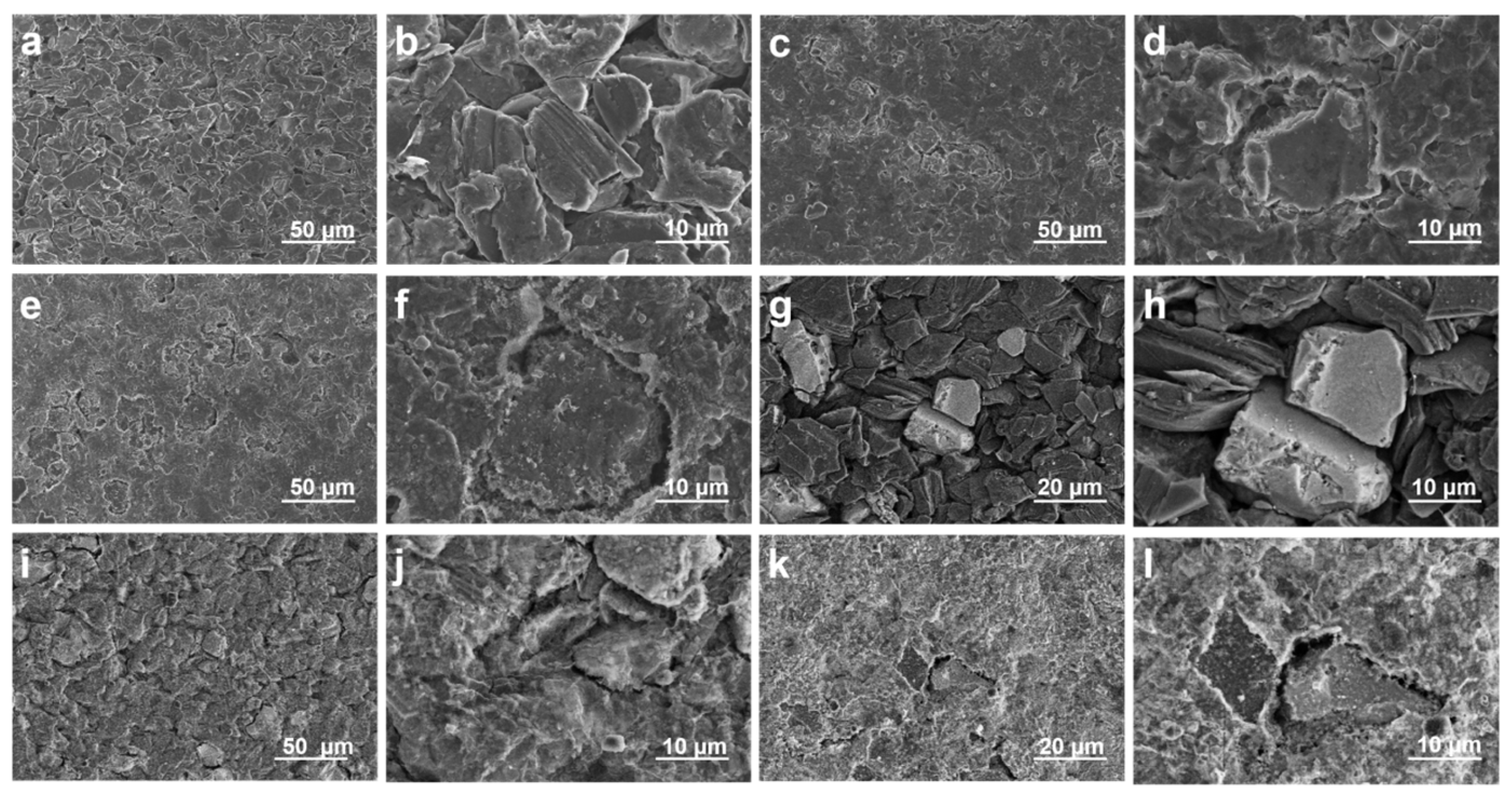
To investigate the impact of LiFSI treatment on the surface structure and morphology, SEM and back SEM were used to view images of raw, prelithiated, and LiFSI-treated silicon anodes (with sizes of approximately 10 um, 20 um, and 50 um, respectively), as illustrated in
Figure 2.
Due to the high solubility of LiFSI in polar electrolytes and the interfacial activity of its fluorosulfonyl groups (-SO2F), we proposed uniform deposition of LiFSI onto prelithiated silicon-based surfaces to ensure homogeneous contact with the anode material. The hydrophilic sulfonic acid groups (-SO2F) in LiFSI act as electrolyte additives, enhancing ionic conductivity and interfacial stability.
In order to verify the promoting effect of LiFSI on the formation of stable SEI film on the negative electrode surface, we tested the SEM images of the negative electrode surface under full charge after two and a half cycles of charging and discharging at a small rate of 0.04 C. It can be found that SEI film was almost invisible on the surface of the original silicon–carbon-negative electrode, and the expanded silicon–carbon particles caused large-scale cracks on the surface (
Figure 2a,b). By EDS testing, it was found that the original electrode surface contained less of the F element required to construct the SEI film (
Figure S1). However, the coverage of SEI film on the surface of the pre-lithium silicon–carbon anode only increased (
Figure 2c,d). EDS tests showed a slight increase in the fluorine intensity on the electrode surface (
Figure S2). This is due to the fact that pre-lithium can provide more active lithium, which can accelerate the formation of the SEI film [
17]. However, it did not change the structure of the SEI film, and the mechanical strength of the SEI film was not improved. Therefore, the expanded silicon–carbon particles made the negative electrode surface show large-scale cracks. At the same time, we noticed that the intensity of the S element on the surface of the pre-lithium electrode increased significantly. This is because the surface of the electrode is residual by pre-lithium, and in the preparation of the SEM test stage, the electrode will inevitably contact the air, resulting in oxidation [
18]. The surface of the pre-lithium +6 M LiFSI electrode saw obvious SEI film covering the electrode surface, and the surface cracks caused by volume expansion were effectively covered (
Figure 2e,f). EDS images also showed that the F element on the electrode surface was significantly increased (
Figure S3). This suggests that LiFSI promoted the formation of SEI films with high stability and ionic conductivity. That is, (1) LiFSI will decompose preferentially and participate in the construction of inorganic-rich SEI components. (2) The sulfonimide groups of LiFSI will coordinate with Li
+ ions to form a stable ionic transport network. At the same time, the decomposition products of LiFSI also exhibit self-healing properties, which can mitigate the SEI film rupture caused by volume expansion.
The surface alterations brought about by the LiFSI treatment were further supported by backscattered SEM images of the same samples, which are shown in
Figure 3. The untreated prelithiated anode’s backscattered SEM images (
Figure 2i,j) displayed contrast changes, pointing to regions of varying composition or oxidation states that were most likely the consequence of side reactions and moisture exposure. The LiFSI treatment anode, on the other hand, had a more uniform structure with less compositional variation (
Figure 2k,l), indicating that the passivating layer was successfully formed. Reducing parasitic reactions and preserving the stability of the electrode–electrolyte contact depends on this homogeneity.
It is evident from the comparison of SEM and backscattered SEM pictures that the artificial SEI layer, which was created by the LiFSI spraying method, greatly enhanced the integrity and surface morphology of the prelithiated silicon anode. The LiFSI treatment is essential for increasing the overall electrochemical performance, especially for cycle stability and early Coulombic efficiency, because it efficiently suppresses side reactions and stabilizes the electrode surface.
Electrochemical performance was examined using single-layer LCO||Si-C/Gr pouch cells (format: 80 mm × 64.2 mm × 0.85 mm, 0.38 Ah). The cyclic voltammetry curves in
Figure 3a exhibited distinct differences in peak shapes and positions between prelithiated electrodes and LiFSI-passivated prelithiated electrodes, indicating that these treatments altered the surface characteristics and internal structure of electrode materials to influence lithium-ion intercalation and deintercalation processes. The prelithiated electrode demonstrated enhanced redox peak intensities attributed to the residual lithium metal enabling more lithium ions to participate in reversible reactions, while its broader current response range reflected elevated electrochemical activity linked to accelerated SEI film formation that improved the lithium-ion transport efficiency. LiFSI-treated electrodes exhibited significantly reduced anode peak intensity at 4 eV and disappearance of parasitic peaks at 4.45 eV, resulting from sulfonyl fluoride groups consuming residual lithium while rapidly forming protective SEI layers to minimize electrode–electrolyte contact and suppress side reactions. The narrowed current response range in LiFSI-passivated electrodes implied enriched inorganic components, like LiF and Li
2S, in SEI layers that optimizd lithium-ion transport paths and reaction kinetics [
19].
Figure 3b demonstrates flatter voltage plateaus in prelithiated electrodes, indicating reduced voltage polarization beneficial for energy density enhancement, whereas the LiFSI-passivated counterparts displayed complex voltage variations in high-capacity regions with lower polarization and higher energy efficiency, corroborating the SEI modification effects observed in CV curves. The initial Coulombic efficiency increased from 77.4% for pristine anodes to 83.4% for prelithiated and 92.9% for LiFSI-passivated electrodes, with irreversible capacity losses decreasing from 22.6% to 16.6% and 7.1%, respectively, confirming LiFSI’s optimization of SEI formation stability (
Figure 3c) [
20]. Rate capability tests (
Figure 3d) showed LiFSI-treated electrodes delivering superior capacities of 118.7, 83.5, 43.9, and 15.9 mAh g
−1 at 0.5 C to 2 C rates due to enhanced SEI ionic conductivity and structural integrity [
21]. After 80 cycles (
Figure 3e), LiFSI-passivated electrodes maintained 89.81% capacity retention, outperforming pristine and prelithiated samples at 88.11% and 88.25%, with prelithiated electrodes initially exceeding 100% capacity retention from residual lithium supplementation but gradually degrading due to SEI fracture–regeneration cycles caused by electrode expansion, leading to lithium loss and impedance from thickened SEI layers [
22]. These findings collectively validated that LiFSI passivation reinforced SEI stability and lithium compensation mechanisms, establishing high-performance silicon-based anodes with optimized interface dynamics.
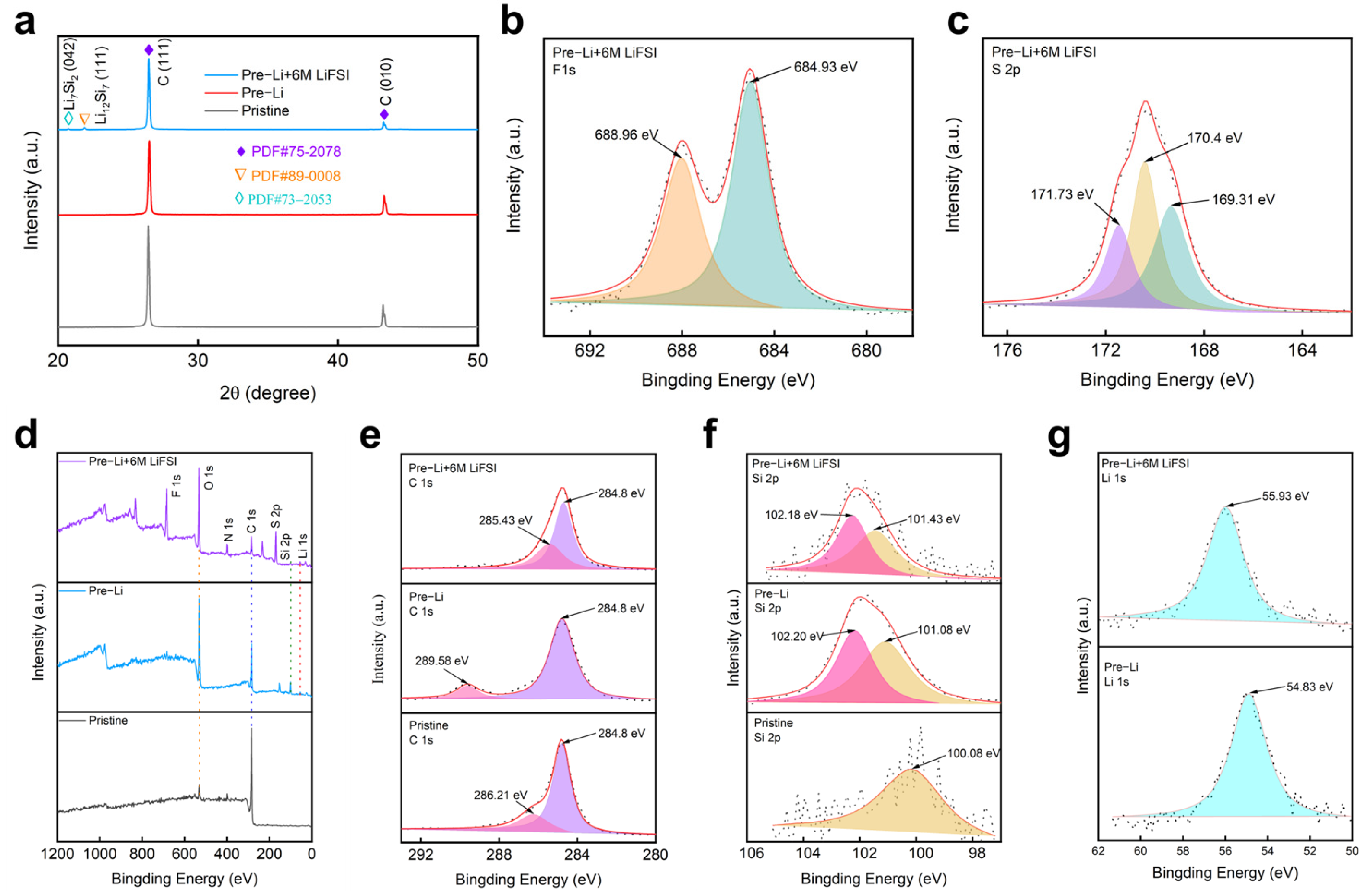
In order to explore the structural changes of the material and further demonstrate the role of LiFSI, phase analysis was performed on different electrodes. The XRD pattern in
Figure 4a reveals the phase evolution of the electrodes before and after prelithiation with surface treatment. The intensity of peak C significantly decreased after prelithiation, indicating structural modifications. The emergence of new lithium–silicon phases further confirmed successful lithiation [
23]. Additionally, the further reduction in peak C intensity after LiFSI treatment suggested increased amorphization, which helped mitigate volume expansion and improve electrode stability. The mechanism of SEI film formation accelerated by LiFSI was further revealed by XPS experiments. As shown in
Figure 4d, it can be found from the full spectrum of XRD that only the pre-lithium electrode had a weak F peak, while the pre-lithium +6M LiFSI electrode had an obvious F peak, indicating the promoting effect of LiFSI on the formation of SEI film. The F1s XPS spectrum in
Figure 4b reveals the chemical composition of the SEI layer after prelithiation +6M LiFSI surface treatment. The XPS spectrum of F1s confirmed the existence of LiF after LiFSI treatment, with a peak at 684.93 eV of LiF and a peak at higher binding energies of 688.96 eV, possibly coming from residual LiFSI after surface treatment [
24].
Figure 4c displays the S2p XPS spectrum of a prelithiated and LiFSI-treated Si-based anode, revealing three characteristic binding energy peaks at 171.73 eV, 170.4 eV, and 169.31 eV, corresponding to distinct sulfur chemical states.
The high-energy peak at 171.73 eV was attributed to S
6+ species (e.g., sulfonate groups, -SO
3−, or sulfate, SO
42−), indicating oxidative decomposition of LiFSI during interfacial reactions. The dominant peak at 170.4 eV corresponded to S
4+ in the sulfonyl group (-SO
2F) of intact LiFSI residues, which enhanced the ionic conductivity of the SEI layer. The low-energy peak at 169.31 eV originated from reduced sulfur species (e.g., Li
2S
x or S
2−), formed through lithium-mediated reduction. This multivalent sulfur evolution demonstrated LiFSI-derived gradient SEI formation, balancing ionic transport and mechanical stress buffering [
25].
Figure 4e shows the XPS C1s spectrum of the three types of electrodes. Carbon peaks at 284.8 eV and 286.21 eV appeared in the spectrum of the pristine electrode, suggesting that carbon mainly formed in the C-C bonds, and carbonyl species [
15,
16]. The carbonyl species converted to carboxylic species (289.58 eV) after prelithiation. Additionally, the peak of carboxylic species shifted to a lower binding energy of 288.8 eV after surface stabilization by LiFSI, suggesting that the carbon species was reduced in chemical reaction with LiFSI [
26].
Figure 4f shows the Si2p spectrum of the three types of electrodes. Apparently, there was SiO
x or LiSiO
x species formed after prelithiation, showing Si2p peaks at 102.2 eV, indicating high reactivity of the surface of the prelithiated electrode and its reaction with atmosphere. The peaks of SiO
x or LiSiO
x shifted to a lower binding energy of 102.18 eV after surface stabilization, suggesting reduced surface reactivity after LiFSI treatment [
27]. Finally, in
Figure 4g, the Li1s spectrum shows two peaks at 55.93 eV and 54.83 eV, associated with lithium compounds such as Li
xSO
yF
z and LiF. The upper spectrum represents the prelithiated electrode with LiFSI treatment, while the lower spectrum corresponds to the prelithiated electrode without surface treatment. The negligible shift and similar intensity between the two spectra suggested that LiFSI treatment did not significantly alter the total lithium content in the SEI but instead influenced its composition and distribution. This implies that the primary role of LiFSI was to optimize the SEI structure, leading to improved passivation, reduced side reactions, and enhanced cycling stability [
28]. The SEI of the surface treatment electrode was analyzed using TOF-SIMS.
Figure 5b shows the depth profile of the electrode in the first 50 nm, revealing SEI characteristics. It was seen that LiF located at the very first 10 nm, constituting an important component of the SEI of the prelithiated anode after surface treatment by LiFSI. Additionally, there was Li
2CN species whose amount increased with the increasing depth, possibly coming from the reaction between the prelithiated electrode and LiFSI. Moreover, Li
3SiO
3 existed as a main substance in the first 50 nm SEI, likely from the prelithiation reaction and the following oxidation, consistent with the results of XPS. Finally, it was seen that Li
2O existed as an important component in the SEI of the LiFSI-treated electrode.
Figure 5a presents the SEI compositions in the format of 3D cubes. It is clearly seen that LiF aggregated at the surface of the LiFSI-treated prelithiated electrode. In addition, Li
3SiO
3 distributed homogeneously, likely following the curvature of silicon–carbon composites. According to the negative-ion TOF-SIMS image shown in
Figure S9, sulfonyl fluoride groups formed a high concentration of LiSO
3 on the electrode surface, which verified the XPS characterization results. In summary, the SEI layer formed by LiFSI passivation treatment was characterized by inorganic compounds, such as LiF, Li
2O, LiSO
3, and LiSiO
3, thereby promoting the formation of a highly stable SEI film.


