Article

Compact Nonvolatile Reconfigurable Mode Converter by Sb2S3 Embedded in 4H-Silicon-Carbide-on-Insulator Platform

Meizhou Intelligent Photoelectric Detection Application Engineering Technology Research Center, School of Physics and Electrical Engineering, Jiaying University, Meizhou 514015, China
*
Author to whom correspondence should be addressed.
Nanomaterials 2025, 15(9), 689; https://doi.org/10.3390/nano15090689
Submission received: 19 March 2025 / Revised: 16 April 2025 / Accepted: 24 April 2025 / Published: 1 May 2025
(This article belongs to the Section Nanophotonics Materials and Devices)

Abstract

:
Nonvolatile switching is emerging and shows potential in integrated optics. A compact nonvolatile reconfigurable mode converter implemented on a 4H-silicon-carbide-on-insulator (4H-SiCOI) platform with a footprint of 0.5 × 1 × 1.8 μm3 is proposed in this study. The functional region features an Sb2S3 film embedded in a 4H-SiC strip waveguide. The functionality is achieved through manipulating the phase state of the Sb2S3. The high refractive index contrast between the crystalline Sb2S3 and 4H-SiC enables high-efficiency mode conversion within a compact footprint. The incident TM0 mode is converted to the TM1 mode with a high transmittance (T) beyond 0.91 and a mode purity (MP) over 91.72% across the 1500–1600 nm waveband. Additionally, when the Sb2S3 transitions to its amorphous state, the diminished refractive index contrast efficiently mitigates the mode conversion effect. In this state, the TM0 mode propagates through the functional region with minimal perturbation, exhibiting T ≥ 0.99 and MPTM0 ≥ 97.65% within a 1500–1600 nm waveband. Furthermore, the device performances were investigated under partially crystallized states of Sb2S3. The proposed structure offers a broad range of transmittance differences (−16.42 dB ≤ ΔT ≤ 17.1 dB) and mode purity differences (−90.91% ≤ ΔMP ≤ 96.11%) between the TM0 mode and TM1 mode. The proposed device exhibits a high robustness within ±20 nm Δl and ±10 nm Δw. We believe that the proposed multi-level manipulation can facilitate a large communication capacity and that it can be deployed in neuromorphic optical computing.

1. Introduction

Phase-change materials (PCMs), a category of compounds, possess amorphous (disordered) and crystalline (ordered) structural states, enabling dramatic changes in their optical properties, e.g., refractive index (n) and extinction coefficient (k) [1]. The phase states are switched reversibly by external electric or optical stimuli. Furthermore, PCMs stably maintain their phase states without the application of constant power, resulting in huge potential in terms of nonvolatile optical switching and memory applications [2]. Ge2Sb2Te5 (GST), a well-established PCM, provides a high refractive index contrast (Δn~2.8) near the wavelength of 1550 nm but suffers from a large extinction coefficient in both the amorphous and crystalline states [3]. In order to minimize the optical loss, Ge2Sb2Se4Te1 (GSST) has been explored, offering a refractive index contrast of ~1.7 and an ultralow loss in the amorphous state [4]. However, the extinction coefficient in the crystalline state should not be ignored. To deal with this issue, Muskens et al. [5] reported two wide-bandgap PCMs, i.e., Sb2Se3 and Sb2S3, with ultralow losses (k < 10−5) in both the amorphous and crystalline states. The low-loss Sb2S3 features a high refractive index contrast of 0.6 in the telecommunications C-band at 1550 nm, thereby rendering it highly suitable for nonvolatile optical switching in programmable photonic integrated circuits (PICs).
Mode-division multiplexing (MDM) leverages distinct spatial modes of light as independent data channels, and it is acknowledged as a promising technique for solving the exponential growth in data consumption [6]. A critical component of MDM is integrated mode-order converters, which enable seamless transitions between waveguide modes, unlocking the potential of spatial multiplexing in PICs. The principles of mode conversion can be summarized into three types: mode reconstitution, mode coupling, and mode evolution [7]. Mode reconstitution converters rely on the manipulation of the phase relationship within the eigenmodes, employing Mach–Zehnder interferometers (MZIs) [8,9], grating-assisted couplers [10,11], slot waveguides [12,13], and metawaveguides [14,15] dedicated to mode decomposition, phase shift, and mode reconstitution. Mode coupling converters need to fulfill the phase-matching condition between the fundamental and high-order modes through asymmetric directional couplers [16,17], Bragg gratings [18,19], metasurfaces [20,21], and so on. Mode evolution converters are based on the adiabatic transformation of the mode field, which fundamentally requires close matching of the modal effective indices. The reported schemes mainly comprise multichannel branching waveguides [22], asymmetric Y-junctions [23], and tapered waveguides [24,25]. Furthermore, reconfigurable mode-order converters can provide flexibility, scalability, and adaptability, crucial for advancing optical technologies in communication, sensing, quantum systems, and beyond. The ability to dynamically manipulate spatial modes opens new avenues for innovation across interdisciplinary applications. Reconfigurable mode-order converters assisted by PCMs, e.g., GSST [26,27], Sb2S3 [28], and Sb2Se3 [29], have been explored and developed. These devices deliver remarkable performance but compromise on their compact device footprint.
Herein, we propose a nonvolatile reconfigurable mode converter implemented on the emerging 4H-SiCOI platform. In the functional region, the Sb2S3 film is embedded in a 4H-SiC slab waveguide with a compact footprint of 0.5 × 1 × 1.8 μm3. When the Sb2S3 is in its crystalline state, its refractive index at a wavelength of 1550 nm is higher than that of 4H-SiC. Such a high refractive index contrast results in remarkable mode conversion. On the condition that the Sb2S3 is switched to its amorphous state, this mode-conversion effect becomes negligible due to the low refractive index contrast between the 4H-SiC and the amorphous Sb2S3 (a-Sb2S3). Through this, a nonvolatile reconfigurable mode-order converter is achieved that is assisted via manipulating the phase state of the Sb2S3.

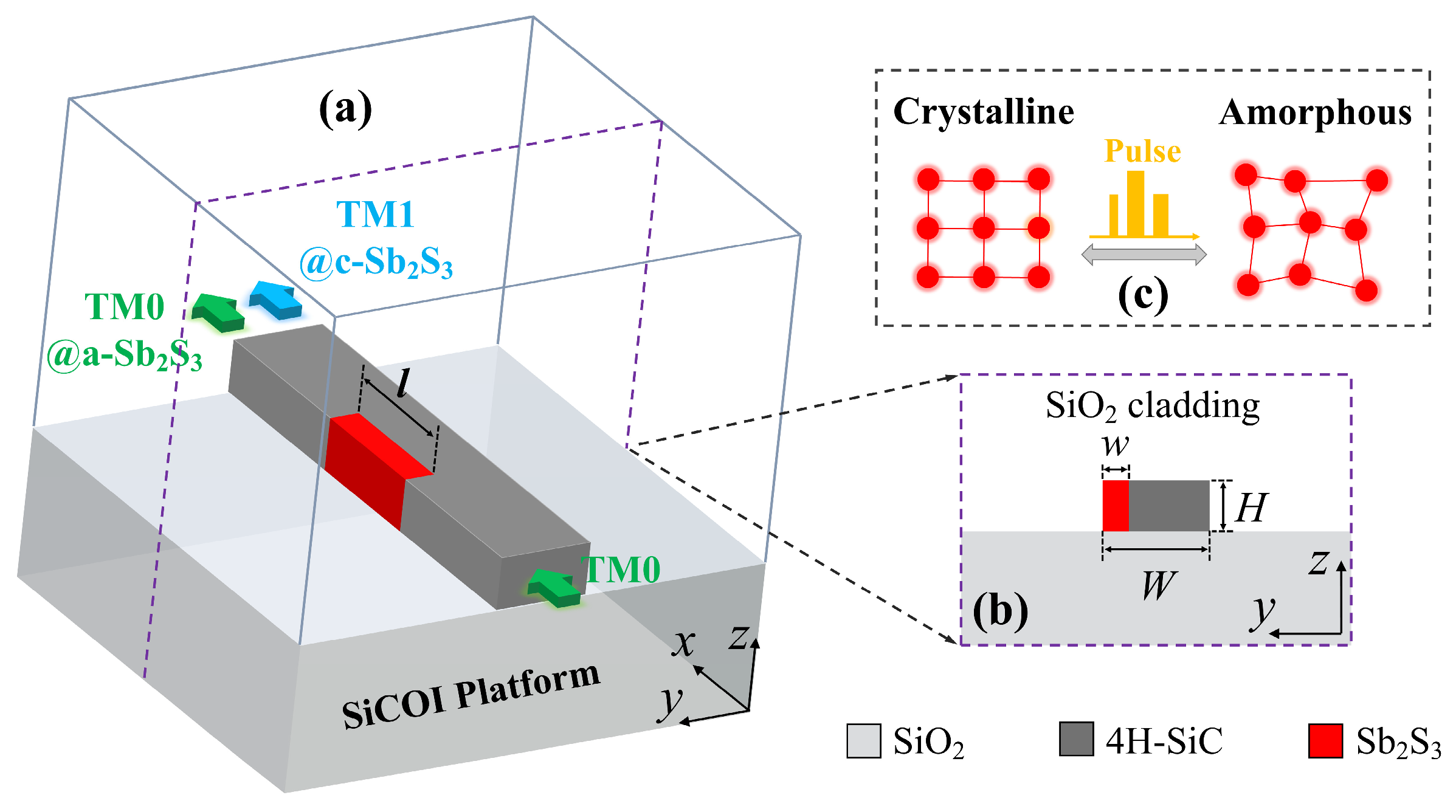
2. Design and Principle

A schematic diagram of the method is sketched in Figure 1a,b. The proposed nonvolatile reconfigurable mode converter is deployed on the emerging 4H-SiC platform. In order to perfectly support both the TM0 and TM1 modes, the width W and height H of the 4H-SiC strip waveguide were set to 1 μm and 0.5 μm, respectively. An Sb2S3 film, a low-loss PCM in both crystalline and amorphous states near the 1550 nm wavelength, is embedded in a 4H-SiC strip waveguide. To improve the fabrication accuracy and reduce the fabrication difficulty, its height h was also fixed at 0.5 μm. Then, its width w and length l were separately set to 0.22 μm and 1.8 μm through parametric sweeps for attaining the highest mode conversion efficiency. As depicted in Figure 1c, the crystalline and amorphous states of Sb2S3 can be converted reversibly and fast by electrical or optical stimulations. The refractive index of Sb2S3 will change with the phase state. According to this rule, a high refractive index contrast exists between the 4H-SiC and the crystalline Sb2S3 (c-Sb2S3), which enables intense mode decomposition, phase shifting, and mode reconstitution effects within the specially designed structure, resulting in a remarkable mode conversion between the TM0 mode and TM1 mode. Once the Sb2S3 is switched in the amorphous state, the refractive index contrast becomes low, resulting in the mode conversion effect being negligible. Thus, a reconfigurable TM0-to-TM1 mode conversion is realized by the manipulation of the Sb2S3 within a compact footprint of 0.5 × 1 × 1.8 μm3.
The key element is the mode conversion that happens with the crystalline Sb2S3. The hybridized-mode interface method is used for the mode conversion [10]. Figure 2a,b depict the two lowest-order hybridized supermodes (HP1 and HP2), which generate, produce the phase shift, and synthesize in the specially designed functional region. In the process of the mode exchange, the transfer matrixes are described as follows:
M = κ 11 κ 12 κ 21 κ 22 ,
and
L = e j ( β 1 β 2 ) l 0 0 1 ,
where κmn (m, n = 1, 2) denotes the coupling coefficient between the incident TM(n − 1) mode and the hybridized supermode HPm, β1 and β2 denote the propagation constants of HP1 and HP2, respectively, and l is the length of the Sb2S3 film. As the middle functional region is mirror-symmetrical, the transfer matrix M can be written as MT because of the optical reciprocity [30]. The matrix elements of M and MT should fulfill the following: κ i k 2 + κ j k 2 1 and κ k i 2 + κ k j 2 1 (ij and k = 1, 2). According to the transfer matrix method, the output of the converter is expressed as follows:
k out 1 k out 2 = M T L M k in 1 k in 2 = e j ( β 1 β 2 ) l κ 11 2 + κ 21 2 κ 21 κ 22 + κ 11 κ 12 e j ( β 1 β 2 ) l κ 21 κ 22 + κ 11 κ 12 e j ( β 1 β 2 ) l e j ( β 1 β 2 ) l κ 12 2 + κ 22 2 × k in 1 k in 2 ,
where κin m and κout m denote the complex amplitudes of the incident TM(m − 1) mode and the output TM(m − 1) mode (m = 1, 2), respectively. To attain a complete mode conversion, it must achieve MTLM = [0 1; 1 0], which should satisfy the conditions |kmn| = sqrt(2)/2 and e−j(β1−β2)l = −1. To ensure the first condition |kmn| = sqrt(2)/2, various structural designs have been reported, such as Mach–Zehnder interferometers, gratings, slot waveguides, and so on. Herein, we chose a high-refractive-index material (crystalline Sb2S3) to be inlaid in a slab 4H-SiC waveguide for a compact footprint. Such a specially designed structure can support the pair of desired hybridized supermodes.
Apart from the optimal coupling coefficients, the second condition is e−j(β1−β2)l = −1, i.e., the desired phase-shifting is equally crucial. To calculate the phase shift between HP1 and HP2, boundary model analyses were conducted by a finite-difference eigenmode (FDE) solver (Ansys Mode Solutions: Waveguide Simulator) [31]. The effective refractive index is expressed as follows [32]:
n e f f = β λ 2 π ,
where β, i.e., the propagation constant, is the wavevector along the guiding direction x-axis. The effective refractive indices (neff) of HP1 and HP2 were calculated as 2.445 and 2.052 with a wavelength of 1550 nm, respectively. The spectral responses of the propagation constants are depicted in Figure 2c. It can be deduced from the second condition, e−j(β1−β2)l = −1, that the π phase shift is vital for the mode conversion. The corresponding coupling length (CL) is described as follows [33]:
C L = π Δ β = π ( β 1 β 2 ) ,
which is illustrated in Figure 2d. The sample (1.55, 1.97) means that the π phase shift can be obtained at a wavelength of 1550 nm when the coupling length is equal to 1.97 μm. Therefore, the length l of the Sb2S3 was initially fixed to 1.97 μm, which is further optimized in the three-dimensional simulation for propagation in Section 3.

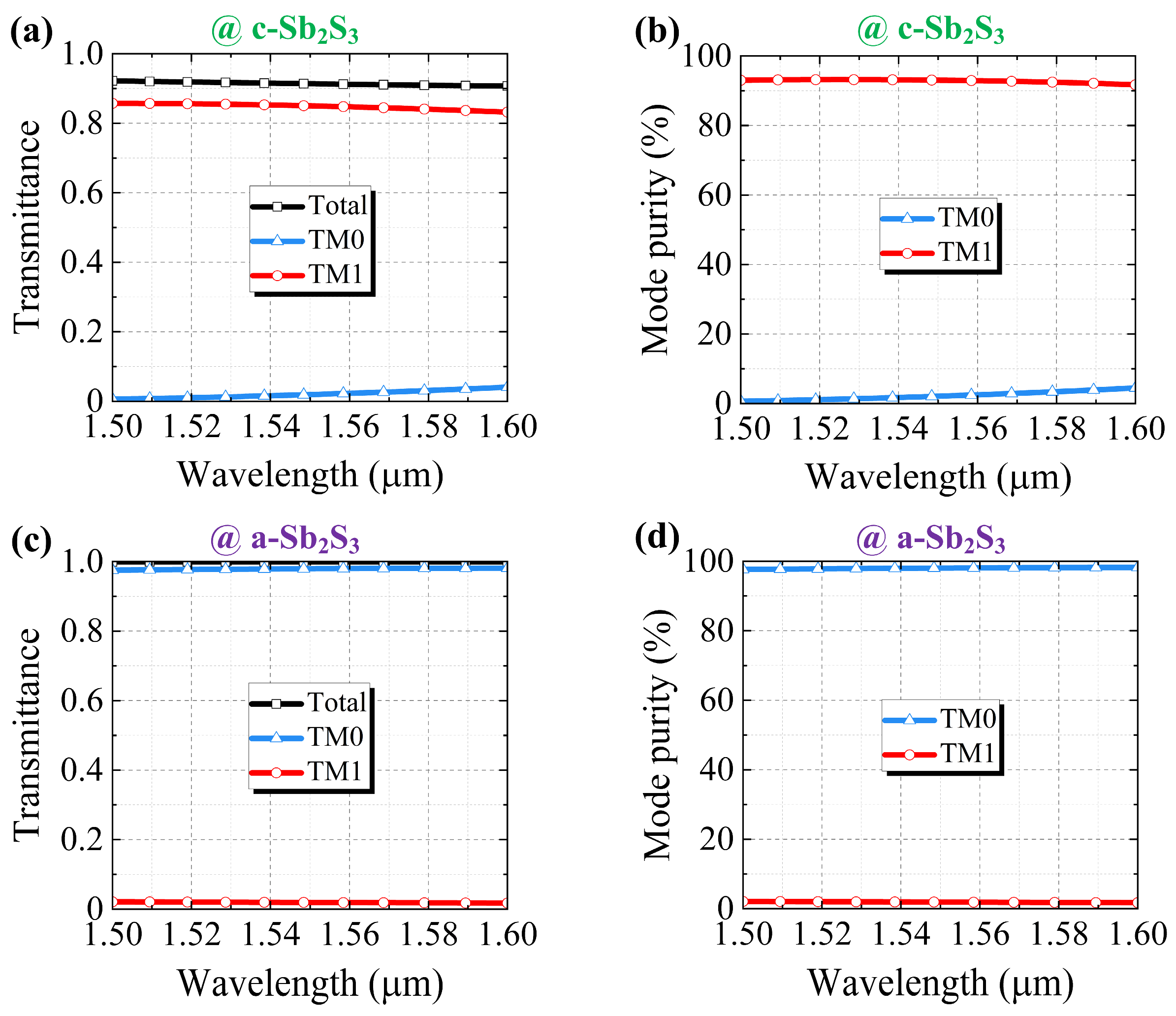
3. Simulation and Performance

To calculate the device’s performance, we utilized a three-dimensional finite-difference time-domain (3D FDTD) method (Ansys Lumerical FDTD Solutions: 3D Electromagnetic Simulator) [34]. The refractive indices of silica and 4H-SiC were set to 1.44 and 2.6, respectively. The crystalline and amorphous Sb2S3 contents were set to 3.308 and 2.716, respectively. The simulated area had dimensions of 5 × 5 × 8 μm3. The boundary conditions were set to the perfectly matched layers (PMLs). The mesh-override section was fixed to dx = dy = dz = 10 nm to guarantee precision in the simulation. The transmittances of both the TM0 and TM1 modes were extracted by a mode expansion solver [35]. The target length l was optimized to 1.8 μm from 1.97 μm by parameter sweeping to attain the highest mode conversion efficiency. The finite-size field distributions and boundary conditions in the 3D FDTD simulations influenced the phase accumulation, resulting in an optimal length shift. When the inlaid Sb2S3 was crystalline, the proposed structure converted the incident TM0 mode to the TM1 mode with a high transmittance (T) of 0.91 and a mode purity (MP) of 93.03% at a wavelength of 1550 nm, as depicted in Figure 3a. The transmission losses were primarily caused by the high refractive index contrast between the crystalline Sb2S3 and the 4H-SiC, which can be mitigated through introducing some structural elements such as tapers, smoothing of the index transitions, or field matching at the expense of higher fabrication accuracy and difficulty. The mode purity is defined as follows:
M P   ( % ) = T T M i T t o t a l × 100 % ,
where TTMi denotes the transmittance of the output TMi mode (i = 0, 1), and Ttotal is the total transmittance. Actually, apart from the output dominant TM1 mode, the other output power consists of the remaining TM0 mode and a higher-order mode (i.e., the TM2 mode). According to the optical reciprocity of the mirror-symmetrical functional region, it can be observed in Figure 3b that the used TM1 mode was converted to the TM0 mode with T = 0.94 and MP = 89.65%. Such a mode conversion relies on the high refractive index contrast between the 4H-SiC and the crystalline Sb2S3. However, abrupt refractive index transitions at the material interfaces induce significant light scattering and Fresnel reflections, which impose inherent limitations on the mode conversion efficiency. The proposed approach can obtain a compact device footprint but compromises in terms of the mode conversion efficiency. Once the Sb2S3 is switched to its amorphous state, its refractive index contrast becomes low, causing the mode conversion effect to disappear. Figure 3c,d show that the TM0 and TM1 modes propagated smoothly through the proposed structure with an ultrahigh transmittance (0.99) and mode purity (98.02% and 96.81%).
The spectral responses of the transmittance and mode purity were calculated with the incident TM0 mode with a 1500–1600 nm waveband. As illustrated in Figure 4a, the transmittance of the TM1 mode (TTM1) remained beyond 0.83, and the transmittance of the TM0 mode (TTM0) remained below 0.041 at a 1600 nm wavelength. As shown in Figure 4b, the mode purity of the TM1 mode (MPTM1) remained above 91.72%, and the mode purity of the TM1 mode (MPTM0) remained lower than 4.49% at a 1600 nm wavelength. Obviously, the TM0-to-TM1 conversion was remarkable with the crystalline Sb2S3. Figure 4c illustrates that the used TM0 mode was almost unaffected through the proposed structure with TTM0 ≥ 0.97 and TTM1 ≤ 0.021 at a 1500 nm wavelength. It is worth noting, as shown in Figure 4d, that MPTM0 ≥ 97.65% and MPTM0 ≤ 2.1% at a 1500 nm wavelength. It can be inferred that the mode conversion effect became negligible with the amorphous Sb2S3.

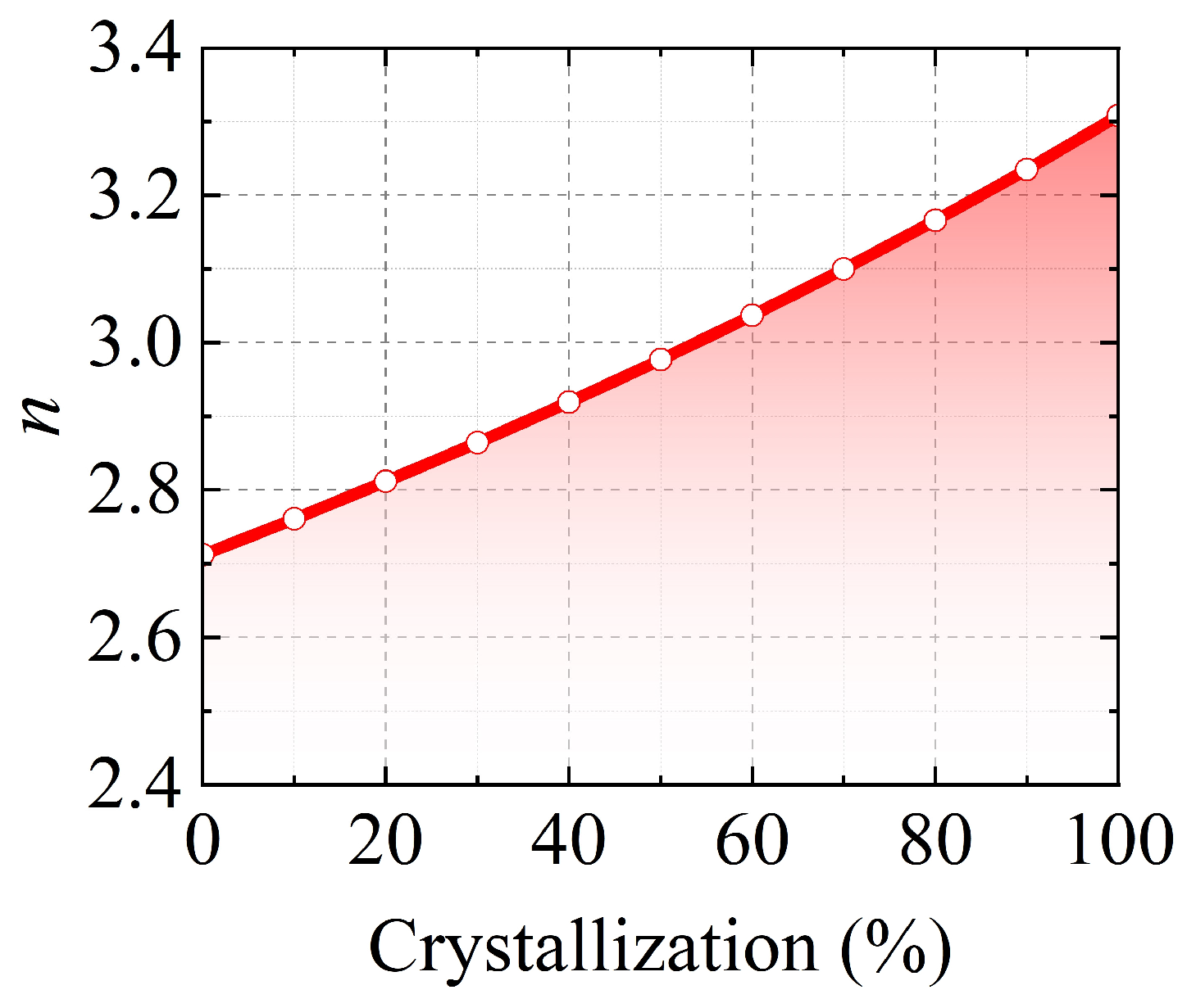
4. Discussion of the Partially Crystallized States of Sb2S3

Apart from their crystalline and amorphous states, phase-change materials (PCMs) also possess intermediate states. It is rather challenging to ascertain whether PCMs are in a completely crystalline or amorphous state. It is essential to conduct an investigation into the performances of devices in intermediate states. Multi-level partially crystallized states have been employed in diverse applications, e.g., multi-level memory [36], image displays [37,38], and photonic convolutional neural networks [3]. Sb2S3 is an emerging PCM that exhibits intriguing intermediate states between its amorphous and crystalline phases. These states are typically induced by normally incident laser pulses and have been validated through Raman spectroscopy. An intermediate state denotes a composite of amorphous and crystalline molecules, characterized by a specific crystallization ratio. The precise selection of peak intensities and durations of control pulses is indispensable for achieving an exact intermediate state. The corresponding effective dielectric constant εeff can be estimated via the effective medium theory in combination with the Lorent–Lorenz relation, as follows [39,40]:
ε e f f ( λ ) 1 ε e f f ( λ ) + 2 = m ε c ( λ ) 1 ε c ( λ ) + 2 + ( 1 m ) ε a ( λ ) 1 ε a ( λ ) + 2
where εc and εa denote the wavelength-dependent permittivity of crystalline and amorphous Sb2S3, respectively. m is the crystallization ratio, ranging from 0 (amorphous) to 1 (crystalline). The calculated refractive indices n are shown in Figure 5, with 10% crystallization ratio step. The theoretical refractive indices were used in the simulations to calculate the device performances.
The device performances encompass the transmittance (T), transmittance difference between the TM0 mode and TM1 mode (ΔT), mode purity (MP), and mode purity difference between the TM0 mode and TM1 mode (ΔMP). The TM0 mode was used in the proposed structure with a wavelength of 1550 nm. Figure 6 depicts the relationship between the above four performances and the crystallization ratio. It can be observed in Figure 6a that TTM0 diminished as TTM1 escalated with the increase in the crystallization ratio. The reason lies in the fact that the mode conversion effect was enhanced as the crystallization ratio was increased. Figure 6b depicts the transmittance difference between the TM0 mode and TM1 mode (ΔT = TTM0 − TTM1), ranging from −16.42 dB to 17.1 dB. When the crystallization ratio was 63%, the transmittances of the TM0 and TM1 modes were equal, so ΔT = 0 dB. As illustrated in Figure 6c, the mode purities of the output TM0 and TM1 modes both equalled 50% at a crystallization ratio of 63%. It is worth noting that the mode purity difference (ΔMP = MPTM0 − MPTM1) possessed a wide range, from −90.91% to 96.11%. To sum up, the proposed structure can provide a broad transmittance difference (−16.42 dB ≤ ΔT ≤ 17.1 dB) and mode purity difference (−90.91% ≤ ΔMP ≤ 96.11%) between the TM0 mode and TM1 mode by controlling the phase state of the Sb2S3. Such multi-level manipulation could attain a large communication capacity and could be deployed in convolutional neural networks for neuromorphic optical computing [3].

5. Robustness Analysis and Suggested Fabrication

As a theoretical study, it was necessary to conduct a robustness analysis. In the functional region, the inlaid Sb2S3 film is pivotal, so the variations in its length Δl and width Δw were considered. In the simulations, the TM0 mode was used in the proposed structure with a wavelength of 1550 nm. When the Sb2S3 was in its crystalline state, the incident TM0 mode was converted into the TM1 mode. As depicted in Figure 7a, the transmittance remained above 91% within ±20 nm deviations of Δl and Δw. It should be noted, as shown in Figure 7b, that the mode purity of the output TM1 mode remained beyond 90% within ±20 nm Δl and ±10 nm Δw. Figure 7c illustrates that the mode purity of the remaining output TM0 mode was below 5.28% within ±20 nm Δl and ±10 nm Δw. In a way, the width w of the Sb2S3 is more sensitive than the length l. Additionally, when the Sb2S3 was switched to its amorphous state, the mode conversion effect became inappreciable because of the low refractive index contrast. As shown in Figure 7d, the transmittance remained over 99.92%. It can be observed in Figure 7e,f that MPTM1 ≤ 2.4% and MPTM0 ≥ 97.4% were achieved within ±20 nm deviations of Δl and Δw. In short, the proposed device held its functionality within ±20 nm Δl and ±10 nm Δw. Finally, the suggested fabrication process is sketched in Figure 8. Commercial high-purity semi-insulating 4H-silicon carbide on insulator (4H-SiCOI) material can be fabricated through sublimation growth [41]. An amorphous Sb2S3 film can be deposited using electron-beam deposition (EBD) [42,43,44,45]. The cladding material, silica (SiO2), is deposited onto the 4H-SiC substrate via the process of plasma-enhanced chemical vapor deposition (PECVD). The process for creating the 4H-SiC strip pattern and performing Sb2S3 lift-off necessitates two-step electron-beam lithography (EBL) procedures, succeeded by reactive ion etching (RIE). The phase state of the Sb2S3 film can be manipulated through a single-pulse laser with over 7000 switching cycles between amorphous and crystalline Sb2S3 [46,47]. Intermediate states can be reproducibly achieved through precise control of external laser pulses, and this has been confirmed via Raman spectroscopy. We anticipate that this will be conducive to the fabrication process.

6. Conclusions

In conclusion, a compact nonvolatile reconfigurable mode converter is proposed, deployed on a 4H-silicon-carbide-on-insulator (4H-SiCOI) platform with a footprint of 0.5 × 1 × 1.8 μm3. The functional region features an Sb2S3 film inlaid in a 4H-SiC strip waveguide. The functionality is realized via manipulating the phase state of the Sb2S3. When the Sb2S3 is crystalline, the high refractive index contrast between the crystalline Sb2S3 and 4H-SiC facilitates high-efficiency mode conversion. The incident TM0 mode is converted into the TM1 mode with a high transmittance (T) of 0.91 and a mode purity (MP) of 93.03% at a wavelength of 1550 nm. It is worth noting that T ≥ 0.91 and MPTM1 ≥ 91.72% were achieved across a 1500–1600 nm waveband. Once the Sb2S3 transitions to its amorphous state, its refractive index contrast is significantly diminished, thereby rendering the mode conversion effect negligible. The used TM0 mode was barely affected through the functional region, with a high transmittance of 0.99 and a mode purity of 98.02% at a wavelength of 1550 nm. It should be noted that T ≥ 0.99 and MPTM1 ≥ 97.65% were maintained within a 1500–1600 nm waveband. Furthermore, the proposed structure exhibits remarkable versatility, offering a broad range of transmittance differences (−16.42 dB ≤ ΔT ≤ 17.1 dB) and mode purity differences (−90.91% ≤ ΔMP ≤ 96.11%) between the TM0 mode and TM1 mode via precise control of the Sb2S3 phase state. The fabrication tolerance analyses revealed its robust performance, maintaining stability within ±20 nm Δl and ±10 nm Δw. We believe this innovative approach to multi-level manipulation not only facilitates enhanced communication capacity but also holds significant potential for deployment in neuromorphic optical computing systems. The unique characteristics and robust performances position it as a promising candidate for advanced photonic applications.

Author Contributions

D.Z.: conceptualization, methodology, software, validation, writing—review and editing. J.C.: software. S.Q.: investigation. D.D.: methodology. J.L.: conceptualization. All authors have read and agreed to the published version of the manuscript.

Funding

This research was funded by the Young Innovative Talents Project for General Universities in Guangdong Province (2023KQNCX076, 2024KQNCX055) and the Talented Research Start-up Project of Jiaying University (2022RC11, 2022RC10, 2022RC09).

Data Availability Statement

The raw data supporting the conclusions of this article will be made available by the authors on reasonable request.

Conflicts of Interest

The authors declare no conflicts of interest.

References

  1. Wuttig, M.; Bhaskaran, H.; Taubner, T. Phase-change materials for non-volatile photonic applications. Nat. Photonics 2017, 11, 465–476. [Google Scholar] [CrossRef]
  2. Parra, J.; Olivares, I.; Brimont, A.; Sanchis, P. Toward nonvolatile switching in silicon photonic devices. Laser Photonics Rev. 2021, 15, 2000501. [Google Scholar] [CrossRef]
  3. Wu, C.; Yu, H.; Lee, S.; Peng, R.; Takeuchi, I.; Li, M. Programmable phase-change metasurfaces on waveguides for multimode photonic convolutional neural network. Nat. Commun. 2021, 12, 96. [Google Scholar] [CrossRef]
  4. Zhang, Y.; Chou, J.B.; Li, J.; Li, H.; Du, Q.; Yadav, A.; Zhou, S.; Shalaginov, M.Y.; Fang, Z.; Zhong, H.; et al. Broadband transparent optical phase change materials for high-performance nonvolatile photonics. Nat. Commun. 2019, 10, 4279. [Google Scholar] [CrossRef]
  5. Delaney, M.; Zeimpekis, I.; Lawson, D.; Hewak, D.W.; Muskens, O.L. A new family of ultralow loss reversible phase-change materials for photonic integrated circuits: Sb2S3 and Sb2Se3. Adv. Funct. Mater. 2020, 30, 2002447. [Google Scholar] [CrossRef]
  6. Li, C.; Liu, D.; Dai, D. Multimode silicon photonics. Nanophotonics 2019, 8, 227–247. [Google Scholar] [CrossRef]
  7. Memon, A.K.; Chen, K.X. Recent advances in mode converters for a mode division multiplex transmission system. Opto-Electron. Rev. 2021, 29, 13–32. [Google Scholar]
  8. Huang, Y.; Xu, G.; Ho, S.T. An ultracompact optical mode order converter. IEEE Photonics Technol. Lett. 2006, 18, 2281–2283. [Google Scholar] [CrossRef]
  9. Oner, B.B.; Üstün, K.; Kurt, H.; Okyay, A.K.; Turhan-Sayan, G. Large bandwidth mode order converter by differential waveguides. Opt. Express 2015, 23, 3186–3195. [Google Scholar] [CrossRef]
  10. Guo, J.; Ye, C.; Liu, C.; Zhang, M.; Li, C.; Li, J.; Shi, Y.; Dai, D. Ultra-compact and ultra-broadband guided-mode exchangers on silicon. Laser Photonics Rev. 2020, 14, 2000058. [Google Scholar] [CrossRef]
  11. Guo, Z.; Xiao, J.; Wu, S. Experimental demonstration of a flexible and high-performance mode-order converter using subwavelength grating metamaterials. Opt. Express 2023, 31, 10744–10757. [Google Scholar] [CrossRef] [PubMed]
  12. Zhang, J.; Qiu, P.; He, R.; Song, X.; Dai, Z.; Liu, Y.; Pan, D.; Yang, J.; Guo, K. Compact mode converters in thin-film lithium niobate integrated platforms. Opt. Lett. 2024, 49, 2958–2961. [Google Scholar] [CrossRef] [PubMed]
  13. Zhao, Y.; Guo, X.; Zhang, Y.; Xiang, J.; Wang, K.; Wang, H.; Su, Y. Ultra-compact silicon mode-order converters based on dielectric slots. Opt. Lett. 2020, 45, 3797–3800. [Google Scholar] [CrossRef]
  14. Lu, J.; Vučković, J. Objective-first design of high-efficiency, small-footprint couplers between arbitrary nanophotonic waveguide modes. Opt. Express 2012, 20, 7221–7236. [Google Scholar] [CrossRef] [PubMed]
  15. Liao, J.; Huang, D.; Lu, Y.; Li, Y.; Tian, Y. Low-loss and compact arbitrary-order silicon mode converter based on hybrid shape optimization. Nanophotonics 2024, 13, 4137–4148. [Google Scholar] [CrossRef]
  16. Garcia-Rodriguez, D.; Corral, J.L.; Griol, A.; Llorente, R. Dimensional variation tolerant mode converter/multiplexer fabricated in SOI technology for two-mode transmission at 1550 nm. Opt. Lett. 2017, 42, 1221–1224. [Google Scholar] [CrossRef]
  17. Zhu, D.; Ye, H.; Liu, Y.; Li, J.; Wang, Y.; Yu, Z. Silicon subwavelength grating-assisted asymmetric directional coupler around 2 μm and its applications. Opt. Laser Technol. 2021, 136, 106789. [Google Scholar] [CrossRef]
  18. Xiao, R.; Shi, Y.; Li, J.; Dai, P.; Zhao, Y.; Li, L.; Lu, J.; Chen, X. On-chip mode converter based on two cascaded Bragg gratings. Opt. Express 2019, 27, 1941–1957. [Google Scholar] [CrossRef]
  19. He, Y.; Zhang, Y.; Wang, H.; Sun, L.; Su, Y. Design and experimental demonstration of a silicon multi-dimensional (de) multiplexer for wavelength-, mode-and polarization-division (de) multiplexing. Opt. Lett. 2020, 45, 2846–2849. [Google Scholar] [CrossRef]
  20. Li, Z.; Kim, M.-H.; Wang, C.; Han, Z.; Shrestha, S.; Overvig, A.C.; Lu, M.; Stein, A.; Agarwal, A.M.; Lončar, M.; et al. Controlling propagation and coupling of waveguide modes using phase-gradient metasurfaces. Nat. Nanotechnol. 2017, 12, 675–683. [Google Scholar] [CrossRef]
  21. Wang, H.; Zhang, Y.; He, Y.; Zhu, Q.; Sun, L.; Su, Y. Compact silicon waveguide mode converter employing dielectric metasurface structure. Adv. Opt. Mater. 2019, 7, 1801191. [Google Scholar] [CrossRef]
  22. Lee, B.T.; Shin, S.Y. Mode-order converter in a multimode waveguide. Opt. Lett. 2003, 28, 1660–1662. [Google Scholar] [CrossRef] [PubMed]
  23. Gao, Y.; Zhang, D.; Xu, Y.; Ji, L.; Chen, W.; Wang, X.; Gao, W.; Sun, X. Compact six-mode (de) multiplexer based on cascaded asymmetric Y-junctions with mode rotators. Opt. Commun. 2019, 451, 41–45. [Google Scholar] [CrossRef]
  24. Dai, D.; Tang, Y.; Bowers, J.E. Mode conversion in tapered submicron silicon ridge optical waveguides. Opt. Express 2012, 20, 13425–13439. [Google Scholar] [CrossRef]
  25. Dai, D.; Mao, M. Mode converter based on an inverse taper for multimode silicon nanophotonic integrated circuits. Opt. Express 2015, 23, 28376–28388. [Google Scholar] [CrossRef]
  26. Jiang, W. Reconfigurable mode (de) multiplexer via 3-D triple-waveguide directional coupler with optical phase change material. J. Light. Technol. 2019, 37, 1000–1007. [Google Scholar] [CrossRef]
  27. Liu, T.; Xu, Y.; Liu, S.; Sun, X.; Zhang, D. Ge2Sb2Se4Te1-assisted non-volatile silicon mode selective switch. Opt. Mater. Express 2022, 12, 2584–2593. [Google Scholar] [CrossRef]
  28. Chen, H.; Wang, T.; Yang, J.; Jia, H. Ultra-compact Sb 2 S 3-silicon hybrid integrated arbitrarily cascaded tunable mode converter. IEEE Photonics J. 2022, 14, 1–7. [Google Scholar]
  29. Fei, Y.; Xu, Y.; Dong, Y.; Zhang, B.; Ni, Y. Nonvolatile phase change material based multifunctional silicon waveguide mode converters. Opt. Laser Technol. 2024, 168, 110006. [Google Scholar] [CrossRef]
  30. Guo, J.; Zhao, Y. Analysis of mode hybridization in tapered waveguides. IEEE Photonics Technol. Lett. 2015, 27, 2441–2444. [Google Scholar] [CrossRef]
  31. Lumerical Inc. Ansys Lumerical MODE. Available online: https://www.ansys.com/products/optics/mode (accessed on 17 March 2024).
  32. Yariv, A. Coupled-mode theory for guided-wave optics. IEEE J. Quantum Electron. 2003, 9, 919–933. [Google Scholar] [CrossRef]
  33. Soldano, L.B.; Pennings, E.C.M. Optical multi-mode interference devices based on self-imaging: Principles and applications. J. Light. Technol. 1995, 13, 615–627. [Google Scholar] [CrossRef]
  34. Lumerical Inc. Ansys Lumerical FDTD. Available online: https://www.ansys.com/products/optics/fdtd (accessed on 1 May 2024).
  35. Lumerical Inc. Using and Understanding Mode Expansion Monitors. Available online: https://optics.ansys.com/hc/en-us/articles/360034902433-Using-and-understanding-Mode-Expansion-Monitors (accessed on 1 May 2024).
  36. Ríos, C.; Stegmaier, M.; Hosseini, P.; Wang, D.; Scherer, T.; Wright, C.D.; Bhaskaran, H.; Pernice, W.H.P. Integrated all-photonic non-volatile multi-level memory. Nat. Photonics 2015, 9, 725–732. [Google Scholar] [CrossRef]
  37. Wang, Q.; Maddock, J.; Rogers, E.T.F.; Roy, T.; Craig, C.; Macdonald, K.F.; Hewak, D.W.; Zheludev, N.I. 1.7 Gbit/in. 2 gray-scale continuous-phase-change femtosecond image storage. Appl. Phys. Lett. 2014, 104, 121105. [Google Scholar] [CrossRef]
  38. Lei, K.; Wang, Y.; Jiang, M.; Wu, Y. Refractive index modulation of Sb70Te30 phase-change thin films by multiple femtosecond laser pulses. J. Appl. Phys. 2016, 119, 173105. [Google Scholar] [CrossRef]
  39. Chu, C.H.; Tseng, M.L.; Chen, J.; Wu, P.C.; Chen, Y.-H.; Wang, H.-C.; Chen, T.-Y.; Hsieh, W.T.; Wu, H.J.; Sun, G.; et al. Active dielectric metasurface based on phase-change medium. Laser Photonics Rev. 2016, 10, 986–994. [Google Scholar] [CrossRef]
  40. Chen, Y.; Li, X.; Sonnefraud, Y.; Fernández-Domínguez, A.I.; Luo, X.; Hong, M.; Maier, S.A. Engineering the phase front of light with phase-change material based planar lenses. Sci. Rep. 2015, 5, 8660. [Google Scholar] [CrossRef]
  41. Guidry, M.A.; Yang, K.Y.; Lukin, D.M.; Markosyan, A.; Yang, J.; Fejer, M.M.; Vučković, J. Optical parametric oscillation in silicon carbide nanophotonics. Optica 2020, 7, 1139–1142. [Google Scholar] [CrossRef]
  42. Chen, R.; Fang, Z.; Perez, C.; Miller, F.; Kumari, K.; Saxena, A.; Zheng, J.; Geiger, S.J.; Goodson, K.E.; Majumdar, A. Non-volatile electrically programmable integrated photonics with a 5-bit operation. Nat. Commun. 2023, 14, 3465. [Google Scholar] [CrossRef]
  43. Chen, W.; Liu, S.; Zhu, J. Pixelated non-volatile programmable photonic integrated circuits with 20-level intermediate states. Int. J. Extrem. Manuf. 2024, 6, 035501. [Google Scholar] [CrossRef]
  44. Chen, F.; Liu, Y.; Liu, X.; Zheng, Y. Multistate spectral-tunable manipulation of mid-infrared emissivity using Sb2S3/GST/VO2. Appl. Phys. Lett. 2023, 122, 191702. [Google Scholar] [CrossRef]
  45. Miller, F.; Chen, R.; Fröch, J.; Fang, Z.; Tara, V.; Geiger, S.; Majumdar, A. Rewritable photonic integrated circuit canvas based on low-loss phase change material and nanosecond pulsed lasers. Nano Lett. 2024, 24, 6844–6849. [Google Scholar] [CrossRef] [PubMed]
  46. Laprais, C.; Zrounba, C.; Bouvier, J.; Blanchard, N.; Bugnet, M.; Gassenq, A.; Gutiérrez, Y.; Vazquez-Miranda, S.; Espinoza, S.; Thiesen, P.; et al. Reversible Single-Pulse Laser-Induced Phase Change of Sb2S3 Thin Films: Multi-Physics Modeling and Experimental Demonstrations. Adv. Opt. Mater. 2024, 12, 2401214. [Google Scholar] [CrossRef]
  47. Gao, K.; Du, K.; Tian, S.; Wang, H.; Zhang, L.; Guo, Y.; Luo, B.; Zhang, W.; Mei, T. Intermediate Phase-Change States with Improved Cycling Durability of Sb2S3 by Femtosecond Multi-Pulse Laser Irradiation. Adv. Funct. Mater. 2021, 31, 2103327. [Google Scholar] [CrossRef]
Figure 1. (a) Schematic and (b) cross-section of the proposed nonvolatile reconfigurable mode converter. (c) The typical phase transformation process of Sb2S3.
Nanomaterials 15 00689 g001
Figure 2. The calculated electric field profiles of (a) HP1 and (b) HP2. The areas surrounded by black dotted lines separately refer to the 4H-SiC waveguide and the embedded Sb2S3 film. (c) The propagation constants of HP1 and HP2 within the functional region. (d) The calculated coupling length (CL) with a varying working wavelength.
Nanomaterials 15 00689 g002
Figure 3. The magnetic field component Hy profiles with the incident (a) TM0 mode and (b) TM1 mode for crystalline Sb2S3. The magnetic field component Hy profiles with the incident (c) TM0 mode and (d) TM1 mode for amorphous Sb2S3. The rectangles surrounded by yellow dotted lines refer to the functional region.
Nanomaterials 15 00689 g003
Figure 4. Spectral response of (a) transmittance (T) and (b) mode purity (MP) with c-Sb2S3. Spectral response of (c) T and (d) MP with a-Sb2S3.
Nanomaterials 15 00689 g004
Figure 5. The refractive index n of partially crystallized Sb2S3.
Nanomaterials 15 00689 g005
Figure 6. The TM0 mode was incident with a wavelength of 1550 nm. The performances of the partially crystallized GSST, encompassing the (a) transmittance, (b) transmittance difference ΔT between the output TM0 mode and TM1 mode, (c) mode purity, and (d) mode purity difference ΔMP between the output TM0 mode and TM1 mode.
Nanomaterials 15 00689 g006
Figure 7. Robustness analysis. (a) Transmittance (T) and mode purity (MP) of output (b) TM0 mode and (c) TM1 mode with varying Δl and Δw for crystalline Sb2S3. (d) T and MP of output (e) TM0 mode and (f) TM1 mode with varying Δl and Δw for amorphous Sb2S3. The TM0 mode is used with a wavelength of 1550 nm.
Nanomaterials 15 00689 g007
Figure 8. Suggested fabrication method employing two steps of EBL: a resist step followed by RIE and EBD to pattern the amorphous Sb2S3, and a resist step followed by RIE to define the 4H-SiC waveguide.
Nanomaterials 15 00689 g008
Disclaimer/Publisher’s Note: The statements, opinions and data contained in all publications are solely those of the individual author(s) and contributor(s) and not of MDPI and/or the editor(s). MDPI and/or the editor(s) disclaim responsibility for any injury to people or property resulting from any ideas, methods, instructions or products referred to in the content.

