Abstract
Particle accelerators are powerful tools in fundamental research, medicine, and industry that provide high-energy beams that can be used to study matter and to enable advanced applications. The state-of-the-art particle accelerators are fundamentally constructed from superconducting radio-frequency (SRF) cavities, which act as resonant structures for the acceleration of charged particles. The performance of such cavities is governed by inherent superconducting material properties such as the transition temperature, critical fields, penetration depth, and other related parameters and material quality. For the last few decades, bulk niobium has been the preferred material for SRF cavities, enabling accelerating gradients on the order of ~50 MV/m; however, its intrinsic limitations, high cost, and complicated manufacturing have motivated the search for alternative strategies. Among these, sputter-deposited superconducting thin films offer a promising route to address these challenges by reducing costs, improving thermal stability, and providing access to numerous high-Tc superconductors. This review focuses on progress in sputtered superconducting materials for SRF applications, in particular Nb, NbN, NbTiN, Nb3Sn, Nb3Al, V3Si, Mo–Re, and MgB2. We review how deposition process parameters such as deposition pressure, substrate temperature, substrate bias, duty cycle, and reactive gas flow influence film microstructure, stoichiometry, and superconducting properties, and link these to RF performance. High-energy deposition techniques, such as HiPIMS, have enabled the deposition of dense Nb and nitride films with high transition temperatures and low surface resistance. In contrast, sputtering of Nb3Sn offers tunable stoichiometry when compared to vapour diffusion. Relatively new material systems, such as Nb3Al, V3Si, Mo-Re, and MgB2, are just a few of the possibilities offered, but challenges with impurity control, interface engineering, and cavity-scale uniformity will remain. We believe that future progress will depend upon energetic sputtering, multilayer architectures, and systematic demonstrations at the cavity scale.
1. Introduction
Superconducting radio-frequency (SRF) cavities are enclosed resonant structures, as shown in Figure 1, used as key components of modern particle accelerators, which transfer electromagnetic energy to charged particle beams, thereby accelerating them to very high speeds with high efficiency. In the early days of particle accelerator development, cavities were made from copper because of its good electrical and thermal conductivity, mechanical robustness, and ease of fabrication [1]. However, when these cavities are operated near room temperature, the electrical resistivity that occurs at that temperature leads to high radio-frequency (RF) losses, and thus very inefficient power transfer from the input RF to the beam. Resistive heating increases quadratically with the RF power, resulting in a loss of efficiency that can lead to high refrigeration demands, reduced quality factors, limiting achievable accelerating gradients, and, in extreme cases, causing structural damage such as cavity melting [2,3]. These limitations pushed the transition to superconducting technology.
Superconducting materials possess surface resistance (Rs) several orders of magnitude lower than copper, thereby reducing RF power dissipation by factors as high as 106. SRF cavities normally operate at cryogenic temperatures around 2 K and can sustain high duty cycles and even continuous waveforms (CW) operation with accelerating gradients (Eacc) of ~45 MV/m [5]. Bulk niobium has been the preferred material for SRF cavities for several decades as it has a relatively high critical temperature (Tc ≈ 9.2 K), large lower critical field (Hc1 ≈ 180 mT), and established manufacturing methods. Continuous improvements to bulk Nb processing, including high-purity refining [6], surface treatments [7], and nitrogen doping [8], have pushed cavity gradients close to the intrinsic limit of ~50 MV/m [9,10]. Even with these advances, the limits of Nb’s inherent superconducting properties, moderate thermal conductivity, high production cost, bulk fabrication complexity, and surface processing continue to limit the progress towards higher accelerating gradients [11,12].
Strategies utilising thin-films have emerged as a preferred alternative, due to the very shallow depth of penetration of RF fields in superconductors (for example, ~40 nm for Nb [13] and 200–350 nm for NbN [14]) implies that SRF performance is primarily a surface phenomenon [2]. This has led to the development of the thin-film-coated cavities, as an alternative to bulk Nb structures. In principle, only a micrometre-thick coating is enough to provide the required superconducting properties, while allowing the bulk of the cavity to be made from copper. Such Nb/Cu cavities have been successfully used at LEP-II [15], HIE-ISOLDE [16], and the LHC [17], where they demonstrated both cost and thermal advantages [18]. However, high-field Q-slope, interfacial voids, film adhesion, stress, impurity incorporation remain challenges [19,20,21,22].
In order to achieve higher performance, the research focus shifted to higher-Tc superconductors such as NbN (~16 K), NbTiN (~17 K), Nb3Sn (~18 K), and MgB2 (~39 K), etc. [23]. These materials reduce BCS surface resistance (RBCS) and operate more efficiently at 4.2 K; however, they have relatively low Hc1, and therefore, they may not achieve as high gradients as implemented with Nb [23]. To overcome this limitation, a theoretical framework introduced in 2006 proposed the use of superconductor–insulator–superconductor (SIS) multilayers, in which alternating superconducting and insulating layers are used to shield the underlying superconductor from applied magnetic fields, thereby increasing the maximum accelerating gradient beyond the limits of bulk Nb [24]. Early studies on NbN and NbTiN multilayers deposited on Nb show an increase in Hc1 and a decrease in Rs, but there remains the challenge of achieving uniform, defect-free insulating barriers [25,26,27,28].
Numerous reviews have focused on superconductivity [29] and SRF technology [2], with a focus on nitrogen doping [10], bulk niobium, and alternative superconducting materials [23,30]. To date, there has not been a review that has specifically focused on sputter-deposited thin films for SRF cavities. We aim to fill this gap by reviewing sputter-coated superconducting thin films for SRF applications, including Nb, NbN, NbTiN, Nb3Sn, Nb3Al, V3Si, Mo–Re, and MgB2. This review will examine the influence of deposition process parameters on the microstructure and superconducting properties of thin films, considering a timeline approach that starts with the earliest studies employing DC magnetron sputtering (DCMS) and extending to recently developed processes like High-power impulse magnetron sputtering (HiPIMS). We will also review achievements, limitations, and remaining challenges, and possible directions for the development of the next generation of SRF cavity coatings. The intended audience will be SRF scientists, thin-film scientists, and the larger community of researchers working on applied superconductivity.
2. Superconductivity and SRF Operation
2.1. Fundamentals
Superconductivity is characterised by three key phenomena: the complete loss of DC resistance, perfect diamagnetism known as the Meissner effect, and the quantisation of magnetic flux [31]. Zero DC electrical resistance only occurs when a superconductor is cooled below its Tc, the temperature at which the transition from the normal to the superconducting state occurs, a phenomenon first discovered by Kamerlingh Onnes in 1911 [32]. The Meissner effect [33], discovered in 1933, demonstrated that superconductivity is characterised by the expulsion of magnetic flux. When a superconductor is cooled below its Tc in an applied magnetic field, screening currents are induced near the surface that generate a magnetic field equal and opposite to the applied field, thereby forcing flux out of the bulk. This perfect diamagnetism continues to stay until the applied field reaches a sufficient strength to overcome the screening currents, at which point the material returns to the normal conducting state. The field strength at which this transition occurs is known as the critical magnetic field (Hc). Along with the critical current density (Jc), these parameters characterise the transition from superconducting to normal conducting behaviour: a material will only display superconductivity when T < Tc, H < Hc, and J < Jc [31].
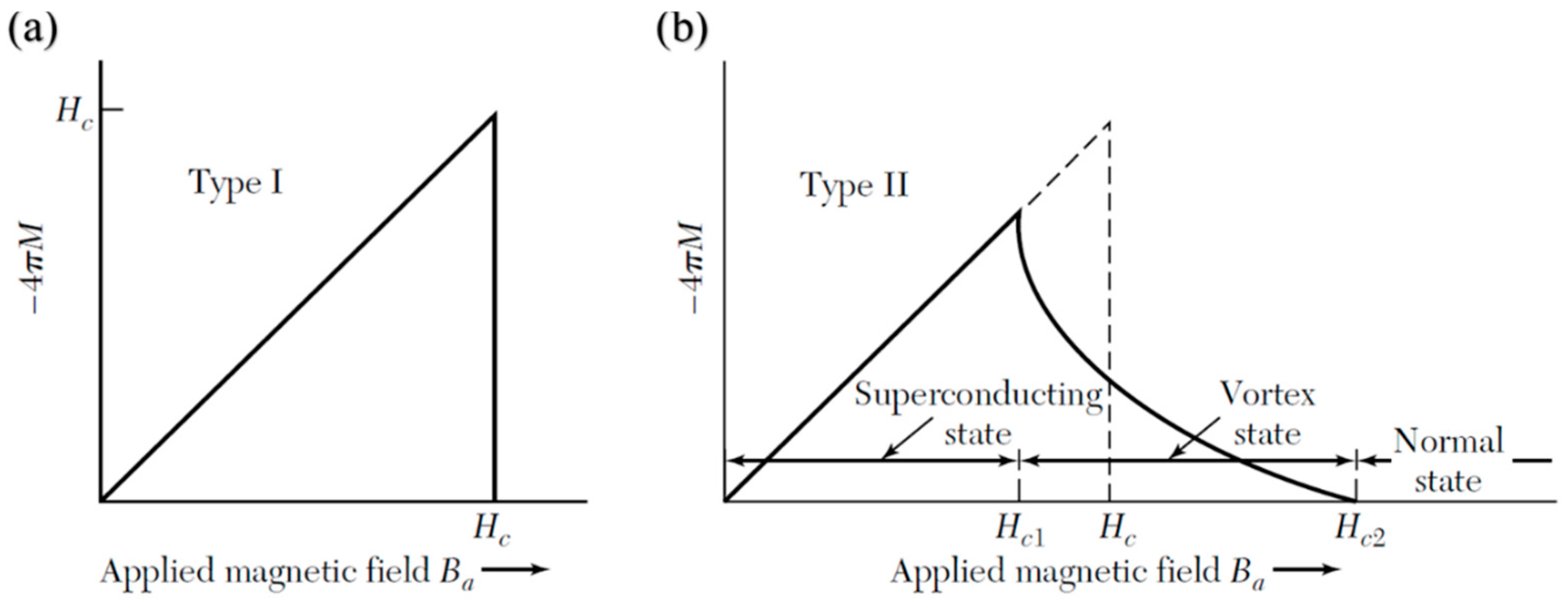
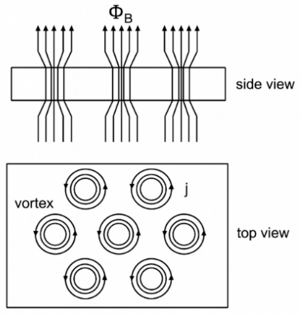
Superconductors are typically classified by their magnetic response. Type I superconductors (Figure 2a) exhibit the Meissner state until Hc is reached, above which they abruptly lose superconductivity and enter the normal conducting state, even if the temperature is still below Tc. In contrast, Type II superconductors (Figure 2b) possess two critical fields. Above the Hc1, they enter an intermediate or mixed state where magnetic flux enters the material in the form of quantised vortices, each carrying a single flux quantum. This was demonstrated experimentally in 1961 by Deaver and Fairbank [34]. These vortices consist of normal-conducting vortex cores surrounded by circulating supercurrents that confine the magnetic field locally, allowing the material to maintain zero DC resistance, as shown in Figure 3, and they are usually pinned at defects or impurities within the material. As the applied field increases, the number of vortices grows until they overlap at the upper critical field (Hc2), beyond which superconductivity is destroyed. A very stable mixed states make Type II superconductors a very valuable material for high-field applications, including SRF cavities [31].
Figure 2.
Magnetic response of type I (a) and type II (b) superconductors showing the critical fields Hc, Hc1, and Hc2. Reproduced from [35].
2.2. Superconductivity Theory
Gorter and Casimir [37] were the first to describe superconductivity using a two-fluid theory. They describe that, below Tc, a fraction of the electrons condense into a zero-resistance state called superfluid, while the rest remain in the normal state. As the temperature decreases, the superfluid fraction increases, allowing lossless current to flow. Superelectrons carry current without loss under a DC field; however, under an AC field, their inertia prevents them from mimicking the oscillating field instantaneously, and the residual normal electron fluid accelerates and creates a resistance effect. Expanding on this idea, Fritz and Heinz London (1935) [38] formulated the London equations, which were able to explain the Meissner effect by introducing the concept of the London penetration depth (λL). This parameter is a measure of the characteristic length (decay length) of an externally applied magnetic field inside a superconductor, and beyond this length, the material is in the Meissner state. The penetration depth is a material property that is dependent on the density, mass, and charge of the superelectrons.
In 1950, Ginzburg and Landau’s [39] development of GL theory is a thermodynamic description of superconductivity near Tc, which describes changes in the superelectron density at normal—superconducting boundaries. They introduced the complex order parameter (Ψ), which is zero in the normal state and greater than zero in the superconducting state, and the superelectron density is defined as ns = |Ψ|2. Based on this, the Ginzburg–Landau coherence length (ξGL) is defined, which is the characteristic distance over which the order parameter changes significantly, and the penetration depth (λGL), which has the same physical meaning as the London penetration depth (λL). Collectively, these two quantities form the Ginzburg–Landau parameter (κ = λGL/ξGL) to characterise the magnetic response of the material at the interfaces. κ < 1/√2 corresponds to type I, while κ ≥ 1/√2 corresponds to type II.
In 1957, Bardeen, Cooper, and Schrieffer introduced the BCS theory [40], which offered the first microscopic model of superconductivity. While it has its limits of applicability, the BCS theory is still the most successful and most widely employed model for conventional superconductors. The theory describes the formation of Cooper pairs below Tc when the phonon-mediated attraction between electrons overcomes thermal agitation. Theoretically, when an electron travels through a metal, its Coulomb attraction to positively charged ion cores locally distorts the lattice. This distortion produces a region with a net positive charge, which attracts another electron in the superconductor. This interaction is called Cooper pairing. Cooper pairing lowers the electronic energy near the Fermi surface and gives rise to the superconducting state. A major prediction of BCS theory is the existence of an energy gap (Δ) between the superconducting and normal states. This energy gap corresponds to the binding energy of Cooper pairs and to break a Cooper pair requires an energy to 2Δ. The energy gap decreases with increasing temperature and essentially goes to zero at Tc; this explains the absence of superconductivity at the transition.
2.3. Surface Resistance in RF Fields
While superconductors possess zero electrical DC resistance, they are observed to have a finite Rs with alternating electromagnetic fields, as is the case with RF use. Above absolute zero, not all electrons are Cooper pairs; some remain as normal electrons. Under a DC, Cooper pairs can flow with no resistance, but under an RF current, Cooper pairs must always reverse their direction of travel. The Cooper pairs have inertia, and thus when they are accelerated and decelerated, a small electric field is induced in the London penetration depth (λL), where supercurrents flow. Moreover, this electric field induces motion in the remaining normal electrons, causing them to absorb energy from the RF field, and this energy dissipates as heat. The temperature-dependent contribution is described by BCS theory and expressed as the BCS surface resistance (, and is given by [40]:
where Δ is the superconducting energy gap, f is the RF, T is the temperature, and A is a material-dependent constant. The constant A incorporates superconductor properties such as the London penetration depth (λL), electron mean free path (l), coherence length (ξ0), and normal-state resistivity, meaning that its value differs from one superconductor to another.
With T = 0 K, RBCS should, in theory, vanish. However, in practice, there will always be a residual surface resistance (Rres) that remains. Rres is temperature independent, and the BCS theory does not take it into account. Rres can originate from a variety of extrinsic influences, including trapped magnetic flux, impurities larger than the coherence length, grain boundaries, oxides, chemical residues, hydride formation, surface roughness, and gas inclusions from the deposition process [41]. Interestingly, studies have shown that Rres is often proportional to the square root of the normal-state resistivity (√ρn) [23], highlighting the influence of normal-state material properties on RF performance. In addition, trapped flux causes fluxon-induced resistance (Rfl). When a cavity cools through Tc, a portion of the external magnetic field is trapped at pinning sites, such as structural defects (grain boundaries and inclusions), which might be created during the fabrication of the cavity. The trapped vortices will oscillate and dissipate energy under RF fields, thus causing more losses. While strong pinning can typically immobilise the vortices and thus reduce losses, weak or partial pinning allows vortices to move in RF fields, drastically lowering performance. Therefore, minimising Rres and Rfl, through magnetic shielding, careful cooldown protocols, and control of impurities and surface defects, is very important for maximising the intrinsic quality factor (Q0) of SRF cavities.
3. SRF Cavity Performance: Figures of Merit and Material Strategies
For SRF applications, the geometry of the cavity and the operating frequency are functions of the particle velocity (β = v/c), with quarter-wave or half-wave designs used for low-β beams and elliptical TM-mode cavities used for high-β beams. Two figures of merit define their performance: the accelerating gradient (Eacc) and the intrinsic quality factor (Q0). The accelerating gradient is defined as
where Vacc is the accelerating voltage and z is the cavity length. The quality factor relates the stored energy to the power that dissipates:
where is the angular frequency, the stored energy, the dissipated power, G the geometry constant, and the surface resistance. With high Eacc, the number of cavities required in an accelerator is reduced, and with high Q0, refrigeration load and operational costs are minimised.
Nb remains the most widely used material for SRF applications, possessing the highest superconducting transition temperature (Tc ≈ 9.2 K) among the elements, relatively high lower critical field (Hc1 ≈ 180 mT at 2 K), and well-established fabrication techniques. Available methods of surface processing and preparation throughout the years, including electropolishing [9], high-pressure rinsing [42], 120 °C baking [43], and nitrogen doping [10], have allowed bulk Nb cavities to reach accelerating gradients near 50 MV/m, which closely approaches the theoretical limits of Nb. Throughout that process, performance-limiting issues like hydrogen precipitation (Q-disease), multipacting, thermal quenches, and field emission have been observed and systematically improved. That said, bulk Nb cavities are costly to manufacture, rely heavily on chemical treatments that may cause hazardous waste, and rely on Nb’s relatively poor thermal conductivity, indicating a need for alternatives. One established route is utilising thin-film superconductors on a copper substrate, with micrometre-scale coatings of Nb providing the superconducting properties and Cu cavities providing mechanical stability and high thermal conductivity. Nb/Cu technology has been successfully implemented in facilities such as LEP-II and the LHC, allowing for a lower cost of materials, higher thermal stability, and lower sensitivity to trapped magnetic flux. However, there are still limitations, the most significant being the Q-slope that occurs at higher fields, as well as the sensitivity to substrate preparation, interfacial voids, and incorporation of impurities during the sputtering process. Research is therefore focused on new energetic deposition methods in a forthcoming chapter.
Besides Nb, other superconductors with higher Tc, specifically Nb3Sn (Tc ≈ 18 K), NbN (Tc ≈ 16 K), and NbTiN (Tc ≈ 17 K), offer an opportunity to decrease BCS surface resistance and thereby increase the overall efficiency for operation at 4.2 K. Other candidates may include V3Si, Nb3Al, and MgB2. The specific superconducting parameters of interest are Tc, Hc, Hc1, Hc2, penetration depth (λ), superconducting gap (Δ), and coherence length (ξ), summarised in Table 1. These data [23] present a positive basis for moving beyond Nb.
Table 1.
Comparison of superconducting material properties relevant for SRF cavities, Adapted from [23].
One potential mechanism to improve the performance of superconductor materials beyond the bulk limits of Nb is through a Superconductor–Insulator–Superconductor (SIS) multilayer system, first proposed by Gurevich. In an SIS structure, the Nb substrate is coated with alternating thin insulating (I) and superconducting (S) layers; the outer S layer has a higher Tc and larger superconducting gap, such as Nb3Sn, NbN or NbTiN. Advantages of a multilayer structure include improved magnetic screening and less RF surface resistance: thin superconducting layers with thicknesses less than their penetration depth (λ) suppress flux entry and increase the effective superheating field, allowing operation beyond Nb’s intrinsic limit of ~200 mT. Additionally, these high-Tc superconductors reduce the BCS surface resistance, especially at 4.2 K, allowing for larger cryogenic savings. Insulating layers decouple neighbouring superconducting films, reduce the Josephson coupling, and can limit the vortex propagation across the multilayer stack, thereby delaying the magnetic flux penetration into the Nb substrate. Multilayers of NbN and NbTiN, which are deposited on a Nb substrate, have demonstrated enhanced Hc1 and lower surface resistances than bulk Nb. The main challenge is to develop an effective insulating layer (AlN or MgO) that is uniform, dense, and defect-free, which can effectively decouple the superconducting films without forming weak links and pinholes. Other dielectrics such as SiO2 and Al2O3 can also be used as insulating layers; however, most recent studies focus on AlN and MgO, which usually provide more uniform barriers. This preference may be related to pinholes or weak spots that have been reported in some oxide barriers [44]. A schematic of the SIS idea is shown in Figure 4.
4. Sputtering Techniques for SRF Thin-Film Coatings
In SRF research, sputtering has become the dominant approach to deposit superconducting thin films, beginning with Nb/Cu technology and then to other compounds such as NbN, NbTiN, and Nb3Sn, etc. In contrast to bulk fabrication routes or diffusion-based coatings, sputtering allows for good control of deposition on non-planar geometries in a scalable way. There are several parameters of the deposition process that can be tuned during the film deposition. Film density, crystallinity, degree of adhesion, and stoichiometry are influenced either directly or indirectly by the plasma characteristics and deposition conditions. Such properties and conditions influence superconducting properties relevant to SRF. This chapter summarises the traditional sputtering techniques found in the literature from the earliest diode configurations to magnetron-based processes, reactive processes, pulsed DC, and finally, modern HiPIMS, discussing the mechanisms through which they operate and the advantages and disadvantages, with attention to their effects on film growth and suitability for RF cavity coatings.
4.1. Principles of Plasma Generation in Sputtering
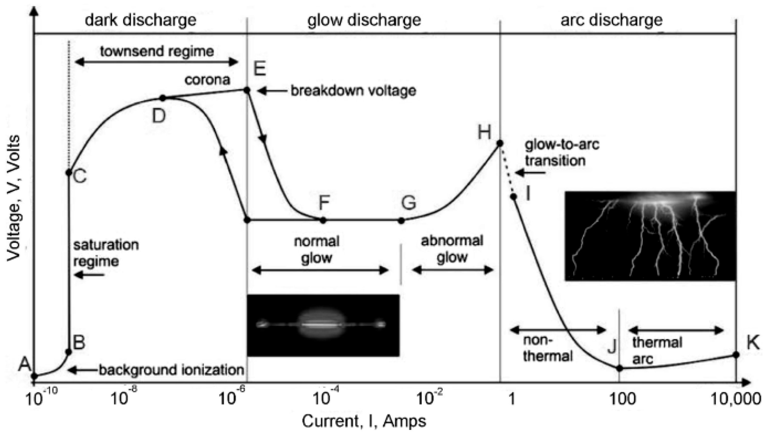
The generation of plasma is the primary step in sputtering, which can be interpreted via the voltage–current characteristics of electrical discharges, as shown in Figure 5. Sputtering begins with the introduction of a neutral process gas, such as argon or krypton, into the chamber. Once an electric field is applied, free electrons are accelerated, leading to collisions that ionise the gas (Townsend discharge). These ions accelerate towards the cathode surface and bombard it, ejecting target atoms and releasing secondary electrons that sustain the discharge. Once the breakdown takes place, the plasma establishes in the normal glow regime, a stable plasma condition where processes yield a visible light emission due to electron–ion recombination. As the electrical potential (applied field) is increased, the discharge enters the abnormal glow regime where carrier densities (1015–1019 m−3) are sufficiently high to sustain sputtering. On further increasing the field, the discharge transitions into arc mode, where significant current densities and target material degradation occur, as this condition is unsuitable for thin-film deposition.
For SRF applications, it is essential that the processes operate in the abnormal glow regime, since stable ion fluxes dictate the uniformity, density and stoichiometry of the superconducting coating. Fluctuations in the plasma conditions directly translate to non-uniform film growth, impurity incorporation, or defects in film microstructure that impede the superconducting properties. Thus, subsequent sputtering techniques developed largely from this basic principle and used magnetic confinement or pulsed power to maintain a stable discharge while increasing the ionisation efficiency.
In the sputtering process, atoms from a solid target are sputtered away by bombarding ions created in a plasma environment. When ions strike the target surface, they may reflect, be incorporated into the lattice, or cause collision cascades leading to the ejection of target atoms. The ejected species travel through the plasma and condense on the surface of the substrate, forming a thin film. Sputtering occurs only when the energy of the incident ions exceeds the threshold energy needed to overcome the forces that bind atoms together, and this threshold energy is a function of several properties, such as the mass ratio between the ion and target atoms, surface binding energy, and the angle of incidence of the ions. Sputtering yield, the number of atoms ejected per incident ion, measures the efficiency of material removal and generally increases with cathode voltage, and is maximised when the mass of the process gas is close to the mass of the target atoms. The energy of ejected atoms is usually of a few eV to tens of eV and described by a Thomson-type distribution [47,48].
In SRF applications, these sputtering mechanisms are directly related to the quality of the coating. For instance, poorer superconducting quality is associated with low-energy sputtered species or excessive scattering at high deposition pressures, resulting in porous, columnar films. Ion bombardment control can increase adatom mobility, and as a result, more dense coatings are formed, which adhere well and have better Tc values with lower RF surface resistance. The most critical parameters are deposition pressure, cathode voltage, substrate bias and temperature, and process gas selection. These parameters will play a significant role in achieving the trade-off between the density, stoichiometry, and stress of the film. There are several sputtering methodologies that have been developed to try to balance these competing requirements, including diode, RF, magnetron, (HiPIMS), etc. However, magnetron-based methods have been the most commonly utilised approach in the study of SRF cavities because they are able to deposit dense, uniform superconducting films on more complicated geometries [49,50,51].
4.2. DC Diode Sputtering
The DC diode system was the first sputtering method introduced. It consists of a very simple configuration with a cathode and an anode. This is typically operated at chamber pressures of 1–100 mTorr and voltages of 2–5 kV, in which Ar+ ions bombard the negatively biased cathode and eject target atoms that coat the substrate. This is a simple and cost-effective method; however, it is only feasible with conducting targets and is prone to arcing with insulators. For SRF applications, films deposited by DC diode sputtering were shown to contain voids, weak adhesion, and high levels of incorporated gas, leading to suppressed Tc and high residual resistance [52,53]. This technique was quickly replaced by magnetron-based techniques, which provide denser and more uniform coatings [47,54].
4.3. RF Diode Sputtering
RF diode sputtering was developed to address the undesirable charge-accumulation problem associated with DC sputtering when using insulating targets. An RF power supply is capacitively coupled to the cathode. The resulting effect is that the target potential switches between positive and negative. In the negative half-cycle of the RF wave, energetic ions strike the target surface to eject atoms, while in the positive half-cycle, the accumulated charge is neutralised by electrons. Because electrons respond to changes more quickly than ions, a net negative self-bias develops on the target, maintaining a constant ion bombardment that affects film density and adhesion. RF sputtering has the advantage of being able to operate at much lower pressures (<1 mTorr) and can be applied to both conducting and insulating targets. However, RF sputtering has a lower deposition rate than DC sputtering, and high power levels can induce thermal stress in brittle targets. For SRF materials, this limitation is compounded by the fact that RF diode sputtering often produces low-density films with limited control over microstructure, which does not meet the requirements for high-quality superconducting coatings [55]. Its utility is mostly as experimental evidence for an alternative method for coating insulating layers. For metallic superconductors like Nb, NbN, or NbTiN, magnetron-based methods have proven much more suitable [47,56].
4.4. Magnetron Sputtering
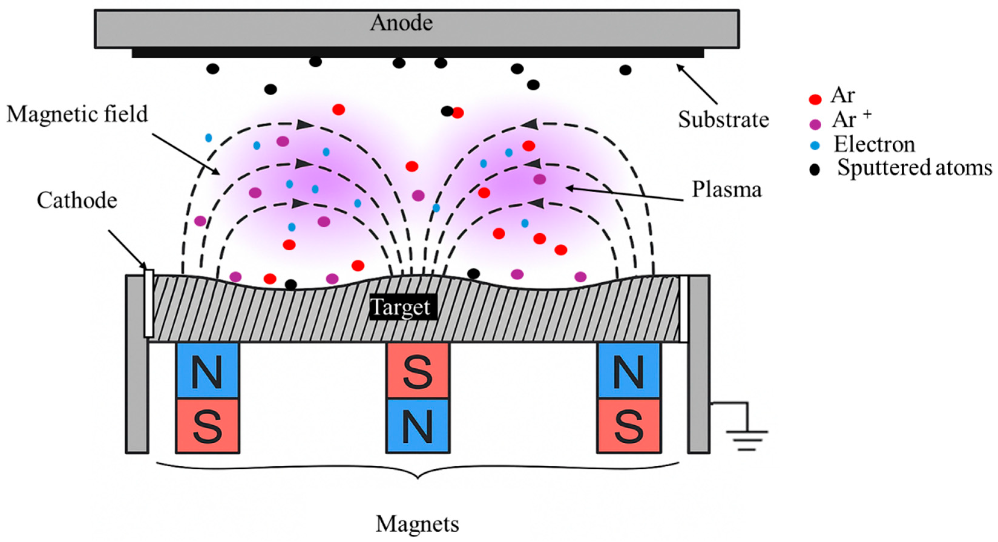
Traditional DC sputtering operates at high voltages (2–5 kV) and relatively high pressures, which significantly decrease deposition rates, limit the mean free path of the sputtered atoms, and promote gas incorporation into the thin film as it grows. Magnetron sputtering improves upon these issues by placing permanent magnets behind the cathode to make crossed electric and magnetic fields (E × B) that effectively trap electrons in close proximity to the target surface (Figure 6). Longer electron paths improve the efficiency of ionisation and cause a racetrack-shaped plasma above the target. The confinement of plasma increases the sputtering yield and deposition rate, while minimising sputtering of the chamber walls. On the downside, it also results in preferential erosion of the target along the magnetic field lines and therefore creates the racetrack wear pattern.
Magnetron sputtering operates at lower voltages (~300 V) and pressures (<5 mTorr) leading to films with higher density and fewer gas defects than diode sputtering. Planar magnetrons are typically used for flat substrates, whereas cylindrical geometries enable the uniform coating of the curved inner surface of SRF cavities. Depending on the type of power supply, i.e., [57]. DC, pulsed DC or RF, different plasma conditions can be established. Out of these options, DC magnetron sputtering (DCMS) became the most widely used technique for SRF studies, allowing the deposition of Nb and compound superconductors in a scalable way. Nb/Cu technology used at LEP-II and the LHC was based on DCMS [58]. However, due to the low energy of sputtered species, deposited films are typically porous and columnar in structure with poor adhesion, which leads to high-field Q-slope and high residual surface resistivity. These drawbacks motivated the development of more energetic variants, most notably HiPIMS [47,57].
4.5. Reactive Sputtering
Reactive sputtering is a commonly used technique to deposit compound films with controlled stoichiometry, most notably nitride and oxide films whose bulk forms cannot be fabricated. This process involves the reactive sputtering of an elemental or alloy target in an atmosphere of a reactive gas (e.g., N2, O2) and the introduction of process gas as an inert gas. The reactive species not only reacts with the sputtered atoms at the substrate, but it forms a compound layer on the target surface as well. Once this layer forms, known as target poisoning, there is a reduction in the sputtering yield. The quality of the film will depend on how these poisoned states are controlled. Operating in the fully poisoned regime provides stable but low-density films, while operating in the transition zone provides higher quality and stoichiometric coatings with a significant reduction in stability. A predominant obstacle is the hysteresis effect. After reducing the flow of reactive gas, the target does not instantaneously revert to its metallic mode, resulting in unstable conditions and, therefore, non-uniform films. The degree of hysteresis depends on the target composition, gas type, pumping speed, and overall geometry of the system. Reactive sputtering has so far been the primary technique to deposit superconducting nitrides such as NbN and NbTiN for SRF applications. Appropriate stoichiometry is important for these sputtered films, since films that are either N-poor or N-rich have strongly suppressed Tc as well as higher surface resistance [47].
4.6. Pulsed DC Magnetron Sputtering
Pulsed DC magnetron sputtering was developed primarily for the purposes of optimising the reactive sputtering of dielectric and compound films, in which the application of continuous DC bias contributes to charge build-up and induces arcing. In this technique, the applied voltage alternates between negative and positive pulses that discharge the target surface more quickly, while sustaining the plasma during the sputtering process. The alternating polarity eliminates arcing, enhances plasma stability, and enables higher current densities than DCMS, thereby enhancing film density for conductive materials. In addition, pulsed DC offers a less complex power supply than RF diode sputtering and can be successfully utilised to deposit dielectric or compound films. In the magnetron configuration, along with the pulsing capabilities, the high plasma density enhances control over stoichiometry in reactive processes. Specifically, with respect to SRF applications, pulsed DC magnetron sputtering offers a reliable route to the deposition of NbN and NbTiN coatings, without the hysteresis and instabilities found in conventional reactive sputtering. According to studies that have been reported, this stabilisation provides denser films and sharper superconducting transitions, with pulsed DC representing an important intermediate option between conventional DCMS and more advanced energetic techniques, e.g., HiPIMS [60,61,62].
4.7. High Power Impulse Magnetron Sputtering (HiPIMS)
HiPIMS is an advanced variant of magnetron sputtering with magnetic confinement and high-power pulsed operation. In HiPIMS, during each pulse, a significant amount of stored energy is released in microseconds, producing plasma densities that can be orders of magnitude greater than those in DCMS. A large proportion of sputtered atoms will be ionised, and the trajectories of the ions can be redirected by substrate bias. This form of deposition provides higher adatom mobility and produces a film with high density, smooth surface, and good adhesion. Additionally, self-sputtering (ionised species circling back to the target to eject additional atoms) also helps sustain the discharge more. The instantaneous power of HiPIMS is very high. At the same time, the pulsed nature of HiPIMS provides a very low time-averaged power, which helps to reduce the possibility of overheating the target [63].
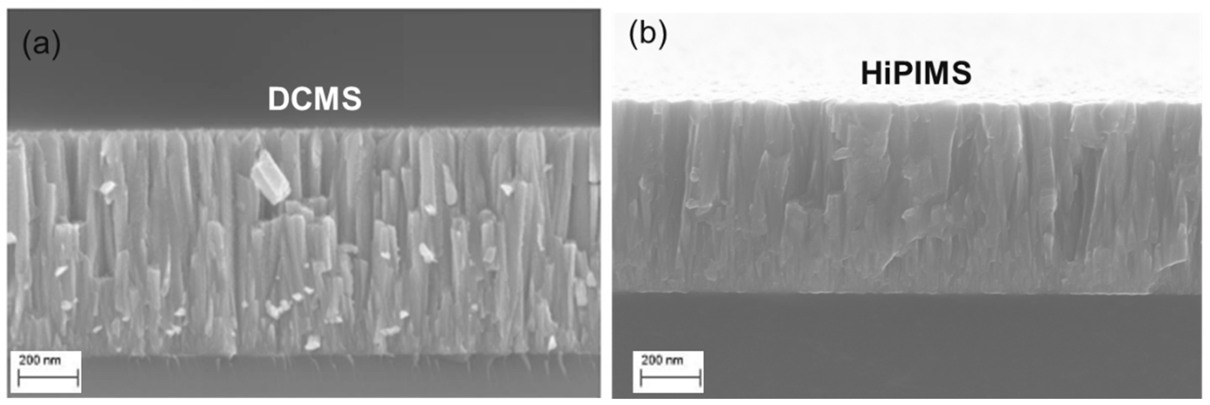
The HiPIMS films are demonstrated to have far greater density and crystallinity than the DCMS films, with much lower void content and superior adhesion. The main concern with HiPIMS is the lower deposition rate, especially at low duty cycles, as well as the greater complexity of the system. However, there are some applications, particularly superconducting coatings like Nb, NbN, and NbTiN, where HiPIMS performance has been extremely useful, especially where dense, defect-free coatings with bulk-like lattice parameters are needed to minimise RF losses and suppress the Q-slope. The benefits of HiPIMS technology are illustrated in Figure 7, which compares the NbTiN thin films deposited at the same pressure (1.8 Pa) by DCMS and HiPIMS. The morphology of the DCMS film is porous, columnar, and features internal voids, with a relatively low Tc (~11.8 K). HiPIMS film, on the other hand, was dense and uniform and provided a distinctly higher Tc (~13.7 K), which directly relates microstructure to superconducting performance. This shows the advantage of HiPIMS to potentially mitigate the limitations of traditional sputtering for SRF cavity coatings [47,49,64].
Figure 7.
Cross-sectional SEM comparison of NbTiN films deposited by (a) DCMS and (b) HiPIMS. Reproduced from [65].
Building on these advances in deposition methods, the following chapter examines how different superconducting materials have been realised through sputtering, with an emphasis on the relationship between deposition conditions, microstructure, and RF performance.
5. Sputtered Superconducting Materials for SRF Cavities
Having surveyed the various techniques for sputtering, we will now shift our focus to the application of sputtering techniques to deposit different superconducting thin films for SRF cavities. The choice of material is critical due to the influence of Tc, Hc, Hc1, Hc2, microstructure, and Rs on cavity performance concerning achievable intrinsic quality factors and accelerating gradients. Nb continues to be the benchmark material, but alternative materials, such as NbN, NbTiN, Nb3Sn, Nb3Al, V3Si, Mo–Re, and MgB2, have also been investigated due to their high Tc. We will review progress in these material systems with emphasis on the effects of deposition conditions on superconductivity, structure, and RF performance.
5.1. Niobium (Nb)
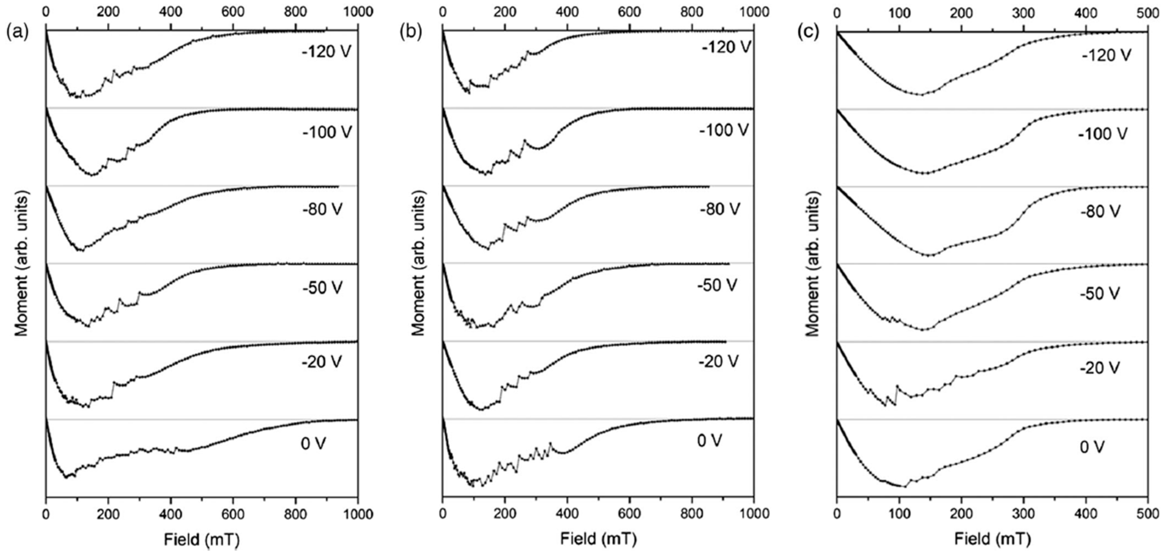
Nb continues to be the preferred choice for SRF cavities. Its relatively high Tc (~9.2 K) compared to other elements and the highest lower critical field (Hc1 ≈ 180 mT at 0 K) have enabled the development of bulk Nb cavities that now operate very close to intrinsic material limits. Nb has an RF penetration depth of about 40 nm, making Nb thin films on Cu attractive because it combines the benefits of Nb superconducting performance with the thermal conductivity, mechanical strength and cost savings of the Cu. Early studies of Nb thin films showed the critical effect of substrate temperature on the microstructure and superconducting properties of Nb thin films. In DCMS experiments in ultra-high vacuum conditions (2-inch Nb target, Ar, 1 mTorr), Nb/Cu films deposited at a substrate temperature of 150 °C exhibited coarser grains, sharper superconducting transitions, and doubled Hc1 (10 mT) when compared to films deposited at room temperature (5 mT), while retaining Tc ≈ 9.2 K [66]. This observation, that a very small variation in substrate temperature could affect the quality of the film, became a guiding principle for future work. With the availability of energetic deposition techniques, researchers sought to investigate this temperature sensitivity further. HiPIMS was used to deposit Nb films, systematically varying the temperature of the substrate between ambient and 650 °C. Cavity tests at 7.8 GHz showed that the room temperature films exhibited very high RF losses (Rs ≈ 181 µΩ at 4.2 K), while the films deposited around 500–550 °C exhibited Rs that was very close to the theoretical BCS limit (≈20 µΩ) with Tc ≈ 9.1 K [66]. Substrate heating was not only a benefit but also a necessity for producing high-quality Nb coatings. The overall impact of the substrate bias and temperature was subsequently explored using HiPIMS in krypton plasma. The films deposited at 700 °C and with a moderate negative bias (−0 to −120 V) produced smooth magnetisation curves (i.e., no flux jumps and stable flux pinning) (Figure 8). These Nb films exhibited upper critical fields (400–500 mT) that were lower than the fields of the Nb films deposited at room temperature and 500 °C (~700–1000 mT), as can be seen in Figure 9, but these Nb films were much more reproducible and stable in the Meissner state [67]. This interesting trade-off, within the context of having a higher Hc2 at low temperatures and improving flux stability at elevated temperatures, clearly highlights the competing interactions involved in optimising Nb films for cavity applications.
Figure 8.
DC magnetic moment versus applied magnetic field at 4.2 K for Nb thin films deposited at (a) room temperature, (b) 500 °C, and (c) 700 °C under different substrate biases. Reproduced from [67].
Figure 9.
Upper critical field (Hc2) of Nb thin films as a function of substrate temperature and applied bias. Reproduced from [67].
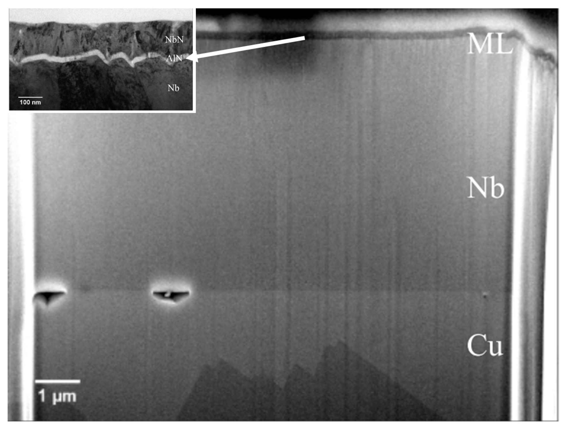
In a comprehensive parameter study systematically varying bias, duty cycle and temperature during the HiPIMS depositions on electropolished copper, it was confirmed that the films with lattice parameters similar to that of the bulk and with large crystallite sizes have the highest Tc (~9.3 K average, up to peaks of 9.6–9.7 K) when applying high substrate bias (≥−150 V) and relatively high substrate temperatures (~290 °C) [68]. In another related study, the same authors developed multilayer Nb/AlN/NbN SIS structures, with the Nb base layers achieving Tc ≈ 9.4 K and Hen ≈ 52 mT alone, with multilayers providing a further improvement to Hen of 64.5 mT. From the FIB–SEM cross sections (Figure 10), it can be seen that interfacial voids and partial delamination at the Cu/Nb interface, indicating that even with SIS multilayers, the quality of the Nb base layer can still limit performance [69].
Figure 10.
SEM image showing a FIB cut through the full thickness of the SIS structure. Reproduced from [69].
Besides the influences described above for bias and temperature, further microstructural investigations revealed the influence of process pressure, angle, and substrate structuring. Rao et al. showed that Nb films sputtered using DCMS on Si at low pressure (0.15 Pa) were dense, smooth, and compressive with low resistivity (~30 µΩ·cm). In contrast, higher pressures (0.60 Pa) yielded porous, tensile films with high resistivity (~375 µΩ·cm). GIXRD showed that an increase in deposition pressure correlates with an increase in lattice strain, and a decrease in crystallite size, consistent with film degradation at high pressure [70]. In subsequent work, the same group reported that deposition at oblique angles (up to 50°) progressively increased surface roughness (0.4 to 1.5 nm) and resistivity (79 to 293 µΩ·cm), while stresses shifted from compressive to tensile [71]. It was also shown that a very strong negative bias (−300 V) during HiPIMS on trenched Si substrates promoted ion bombardment and re-sputtering, effectively suppressing self-shadowing and producing dense, planarized Nb films, showing that strong ion bombardment during HiPIMS enables uniform deposition on structured substrates [72]. This ability for uniform deposition on structured substrates is critical for coating the complicated geometries of SRF cavities.
The deposition process alone cannot solve all issues; therefore, post-deposition treatments were investigated. It has been shown that the nanosecond pulsed laser annealing of DC-sputtered Nb/Cu films at 450–650 °C modified the surface morphology. As shown in Figure 11, a single irradiation laser cycle smoothed granular films, while five cycles reduced surface roughness by approximately 75%. Increased structural refinement was correlated with reduced oxygen/hydrogen contamination and improved connectivity of grains, while all the films exhibited a Tc of ~9.3 K. This study showed that laser annealing can effectively reduce surface roughness and Q-slope-related defects [73].
Figure 11.
Environmental Scanning Electron Microscopy (ESEM) images of Nb/Cu films deposited at 450 °C by DC magnetron sputtering: (a) as-deposited (b) after laser annealing at 1.30 J/cm2 (one cycle), and (c) after laser annealing at 1.30 J/cm2 (five cycles). Reproduced from [73].
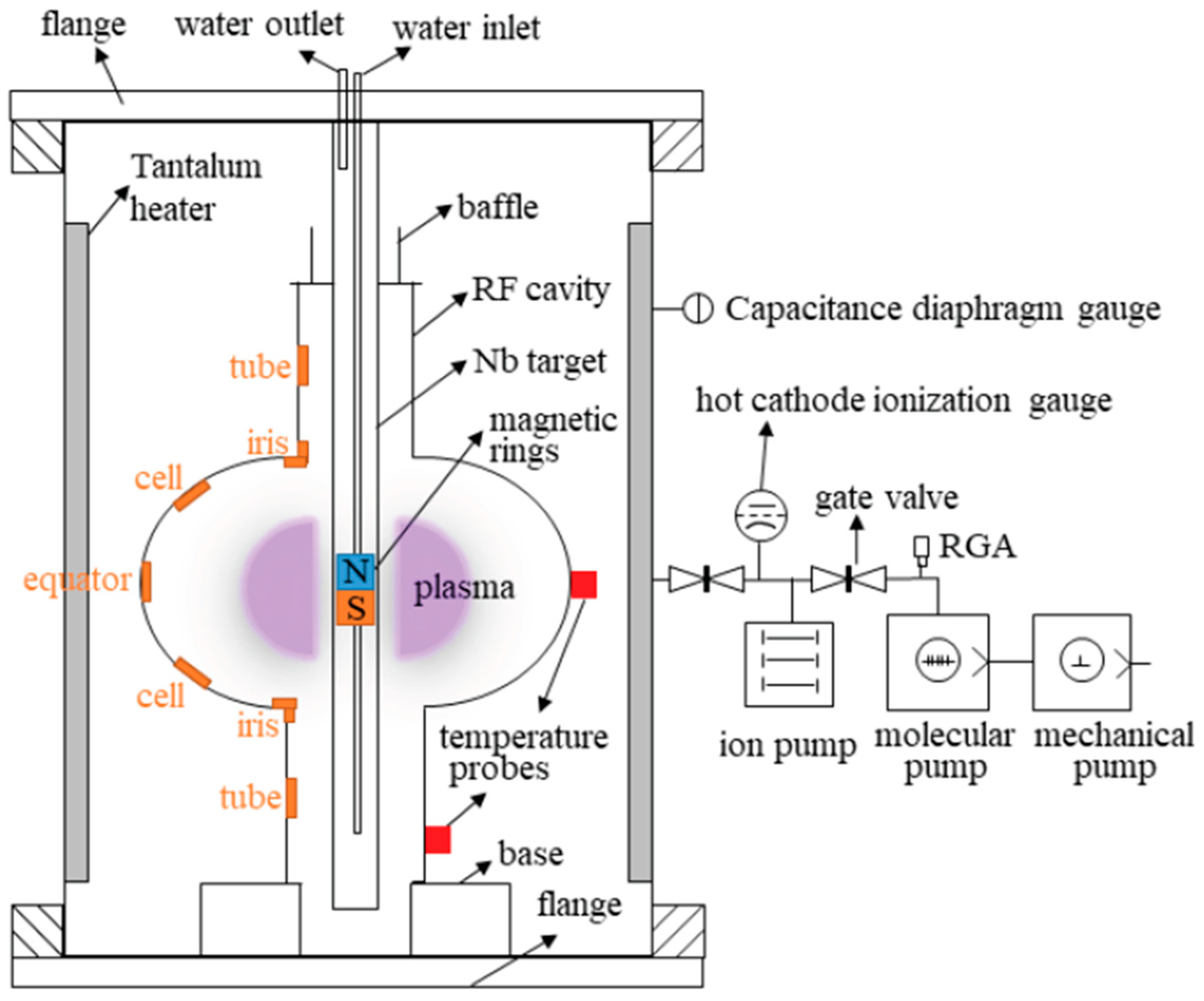
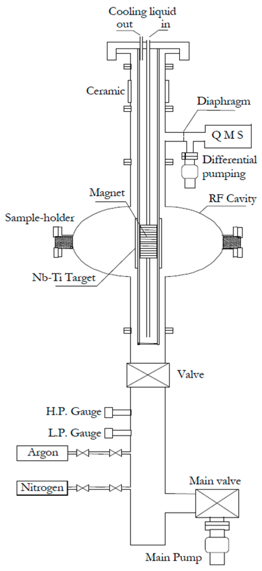
This progress encouraged cavity-scale demonstrations. HiPIMS was used to deposit ~1 µm Nb films on Cu substrates and SRF cavities. The films grown on Cu substrates displayed bulk-like lattice parameters, smooth, dense microstructures, and a Tc of ~9.5 K. The first cavity coatings achieved Q values in the mid-to-high 109 range up to ~10 MV/m, limited by field emission. Following the high-pressure water rinse and the optimisation of the cathode positioning, accelerating gradients of ~21 MV/m were achieved without field emission, demonstrating that HiPIMS can produce bulk-like Nb films [42]. To further investigate coating uniformity inside cavities, a custom HiPIMS deposition system was developed, which consisted of a coaxial cylindrical magnetron with a movable magnetic ring and a cylindrical Nb target, to coat a 1.3 GHz dummy cavity (Figure 12). Nb films deposited in Kr plasma (0.6 Pa, 490 V, 110 A, 200 °C, 6 h) displayed dense, bulk-like grains (300–800 nm) with RRR ≈ 33. The lattice parameters are close to those of bulk Nb. While all the coatings at the equator were dense and well-adhered, nanoscale porosity was observed in the vicinity of the iris. The Tc was constant at 9.24–9.27 K, with a narrow ΔT ≈ 0.2 K, this provides further evidence that HiPIMS can produce high-quality cavity coatings. The presence of nanoscale porosity at the iris suggests that careful optimisation of the deposition parameters is still required to create fully uniform films and ensure reliable suppression of the Q-slope in Nb thin-film cavities [74].
Figure 12.
Schematic of the HiPIMS deposition system for coating 1.3 GHz Cu cavities. Reproduced from Duan et al. [74].
Finally, efforts have been made to further improve cavity performance using annealing approaches. It has been shown that in situ annealing of HiPIMS Nb films at 340 °C improved the quench field from 10.0 to 12.5 MV/m. Furnace annealing at 600 °C and 800 °C further increased the quench field to 13.5 and 15.3 MV/m, respectively. Prolonged annealing at 800 °C (6 h) pushed the quench field to 17.5 MV/m. However, annealing at 900 °C caused Q-switching. This shows that controlled annealing treatments can reduce the medium-field Q-slope, while excessive heating can introduce new instabilities [75]. The results achieved with Nb thin films (~21 MV/m with Q ≈ 109) [42] are promising, although not at the performance level of state-of-the-art bulk Nb cavities (~50 MV/m with Q ≈ 1010) [76]. Other issues, including interfacial voids, film uniformity and medium-field Q-slope suppression, suggest Nb thin films are still an area of research.
5.2. Niobium Nitride (NbN)
NbN is one of the alternative superconductors to Nb for SRF applications. NbN Tc (~16 K) is higher than Nb, which allows for higher-temperature operation, and it has a greater chemical stability, making it resistant to surface oxidation. NbN is also a potentially interesting option for SIS multilayers, although bulk NbN intrinsic Hc1 (~20 mT) is less than that of bulk Nb.
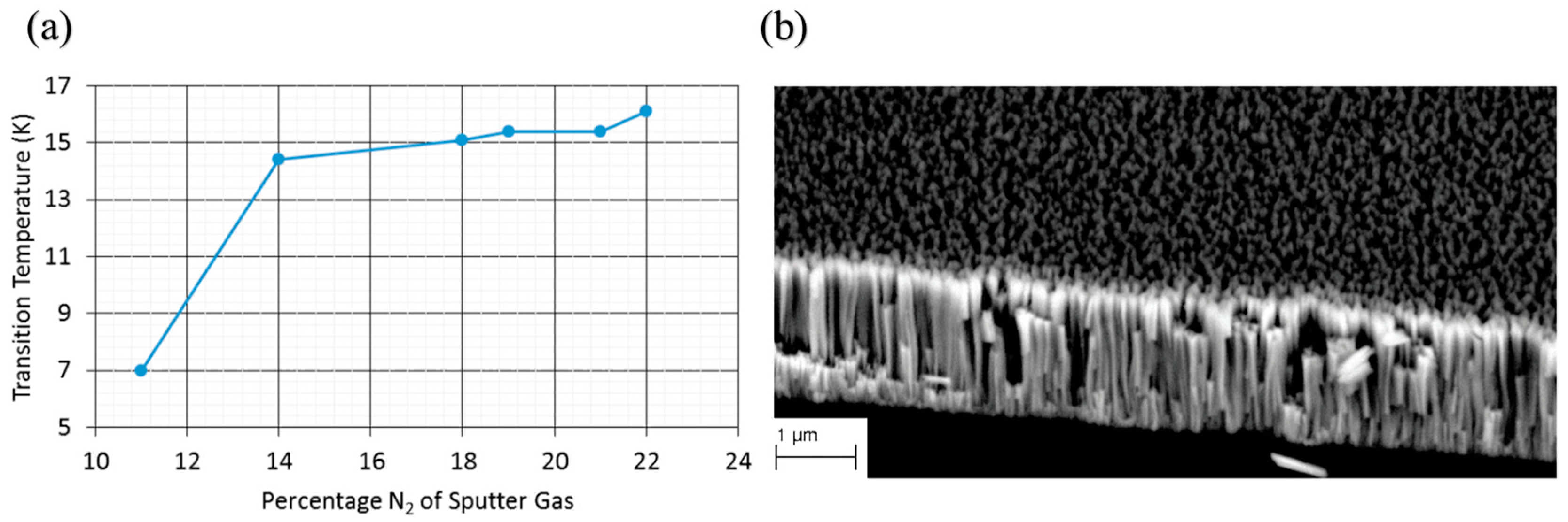
Earlier studies confirmed the feasibility of NbN coating on cavities, but they also revealed the intrinsic limitations of these coatings. Reactive sputtered NbN films deposited at 510–580 °C on Nb substrates exhibited Tc of 16.2–16.5 K, Hc1 ≥ 10 mT, and Rs ≈ 6.4–6.9 µΩ along with improved chemical stability and lower sensitivity to trapped flux as compared to Nb. However, their RF performance was limited by columnar microstructures and the intrinsically low thermal conductivity of NbN [77]. Multilayer concepts were developed to overcome these limitations. NbN films sputtered on Si substrates, and on Nb-SiO2-Nb multilayers on Nb plates, displayed a Tc of ~14.4 K. The multilayers achieved Hc1 ≈ 220–230 mT at 2 K, exceeding the bulk Nb limit (~180 mT). This was the first experimental confirmation that NbN-based S-I-S multilayers can exceed the Hc1 limit of Nb, which confirms the theoretical prediction [78]. Given NbN was established as a viable superconductor for S–I–S multilayers, optimisation of microstructure and NbN stoichiometry became the research focus. The HiPIMS deposition of NbN on Si(100) using Kr–N2 plasmas showed a very high sensitivity to nitrogen content. At 385 °C, Tc increased with increasing N2 partial pressure to a maximum of 16.1 K at ~22% N2 (Figure 13a). Even with this improvement, the films exhibited a columnar morphology with voids and relatively high resistivity (~835 ± 260 µΩ·cm), evident in Figure 13b. Film depositions performed at room temperature displayed an even lower Tc (10.3 K at 22% N2) with significantly higher resistivity (~2094 ± 650 µΩ·cm), indicating that elevated temperatures are essential for adequate mobility of the adatoms to ensure dense growth [79].
Figure 13.
(a) Transition temperature of NbN thin films as a function of N2 partial pressure (substrate at 385 °C). (b) SEM cross-section of an NbN thin film (385 °C, 22% N2). Reproduced from [79].
Complementary studies showed that the superconducting properties of NbN are very sensitive to stoichiometry. NbN films were deposited at room temperature by reactive DCMS on SiO2 with an N2 fraction of 0.5–30%, and a 50 V rf substrate bias. The films exhibited nearly stoichiometric δ-NbN (RN2 = 8–16%) with a Tc ≈ 12.8–13.2 K and a Hc2 (0) ≈ 28–30 T. N-deficient films (1–2%N2) exhibited highly suppressed Tc ≈ 2.5 K, while N-rich films (≥20% N2) exhibited degraded Tc ≈ 6–7 K. The films were non-superconducting at ~30% N2. Both deficiency and excess N2 caused higher resistivity and lowered Tc. This implies that good superconducting properties at room temperature, as well as elsewhere, require controlled stoichiometry [80]. To determine if NbN could serve as a direct coating material for SRF cavities, Leith et al. deposited NbN on polycrystalline Cu substrates using reactive DCMS and evaluated different pressures and N2 flow rates. At 6 × 10⁻³ mbar and a N2 fraction of ~8%, a δ-NbN (200) phase was obtained with a Tc ≈ 12 K and Hen ≈ 13 mT, and the microstructure was dense, with no apparent voids. At 1.4 × 10⁻² mbar, δ-NbN(111) was the predominant phase with a high Tc of up to 16.1 K, but low Hen ≈ 5.0 mT due to the formation of faceted and discontinuous growth. Excess N2 (>15) caused secondary phases, severely reducing both Tc and Hen [68]. Thus, there is a clear trade-off, as higher Tc can be attained, but at the expense of the effectiveness of magnetic screening (Hen) from the porosity or other secondary phases. The impact of lattice parameters and film thickness on superconducting properties was studied by depositing epitaxial NbN films on MgO(100) via DCMS. A linear correlation was identified between Tc and lattice parameters, shown in Figure 14a. There was no noticeable dependence of Tc on thickness (Figure 14b). Hc1 has a significant thickness dependence, ~100 mT for an 80 nm film compared to ~20 mT for bulk NbN (Figure 14c). Therefore, it is necessary to control the sub-penetration-depth thickness for multilayer applications [81].
Figure 14.
Variation in superconducting properties in NbN thin films: (a) Tc vs lattice constant, (b) Tc vs thickness, and (c) Hc1 vs thickness (the thick line represents the calculated Hc1 enhancement for NbN thin films assuming a coherence length of 4 nm). Reproduced from [81].
Based on these results, Burton et al. showed strong field enhancements in multilayers. Nb/MgO/NbN trilayers with ~85 nm top layers of NbN exhibited Tc ≈ 13 K, and Hc1 ≈ 210 mT; confirming that NbN multilayers are excellent candidate materials for SIS screening in SRF cavities [25]. In summary, NbN has been studied mainly within multilayer architectures, although standalone NbN coatings on Cu have also been investigated. Control of the stoichiometry and thickness has been shown to lead to Tc values up to ~16 K and moderate Hen. However, the use of NbN in SIS multilayers is the most viable application, where thin, controlled NbN layers can help to extend Nb cavity performance beyond its intrinsic limits.
5.3. Niobium Titanium Nitride (NbTiN)
Alloying NbN with Ti has been investigated as a way to enhance the properties of nitride-based superconductors for SRF applications. NbTiN, compared to NbN, has lower normal-state resistivity, smoother microstructures, and higher Tc values, while maintaining the chemical stability of nitrides. These properties make NbTiN an attractive compound for applications either as a direct coating or as the outer superconducting layer in SIS multilayers.
The first experiments have shown that Ti alloying of NbN will significantly reduce resistivity without degrading superconductivity. Films deposited by reactive DCMS at 200–600 °C on sapphire substrates have achieved Tc values greater than 16.8 K and exhibited a relatively sharp transition (ΔTc ≤ 0.1 K). With regard to NbN (ρ ≈ 170 µΩ·cm, Rs ≈ 5.4 nΩ at 200 °C), the addition of Ti decreased the resistivity to ~62 µΩ·cm and Rs to ~2.1 nΩ without affecting Tc. All of these improvements can be achieved at significantly lower deposition temperatures, positioning NbTiN as a more attractive option than pure NbN for SRF applications [82]. Expanding on this work, additional studies were conducted to investigate RF performance relevant to cavity behaviour. Optimised (Nb0.55Ti0.45)N coatings on Cu and SiO2 substrates achieved Tc ≈ 16.0–16.3 K with relatively sharp transitions (ΔTc ≈ 0.1 K). RF tests in a 4 GHz cavity showed residual surface resistance as low as 40 nΩ at 1.6 K, comparable to bulk Nb; however, when the cavity was tested at 4.2 K, the Rs was up to 5 times lower than that of Nb. A maximum RF field of 34 mT (Eacc ≈ 8.5 MV/m) was achieved before quench, which confirms the potential of NbTiN films for higher-temperature SRF operation [83]. Cylindrical magnetron methods were subsequently developed to extend these results to geometries at the cavity scale. Nb0.35Ti0.65 films were deposited inside 1.5 GHz seamless Cu cavities using a Nb–Ti central cathode, which is adapted from the CERN Nb/Cu setup (Figure 15). Optimised films on quartz achieved Tc ≈ 15.5 K, RRR ≈ 1.45, and ρ0 ≈ 35 µΩ·cm. Coatings on Cu cavities displayed Tc ≈ 14.2 K, residual resistance ~350 nΩ, and a BCS resistance of 55 nΩ at 4.2 K, which is significantly lower than Nb/Cu (~400 nΩ) and bulk Nb (~900 nΩ) at the same frequency, although residual resistance remained high. These results established NbTiN as one of the first non-Nb films realistically tested in SRF cavities [84].
Figure 15.
The sputtering system for the deposition of NbTiN thin films inside 1.5 GHz resonators. Reproduced from [84].
After demonstrating the feasibility of the cavity, optimisation turned to controlling deposition temperature, buffer layers and substrate. Films deposited on oxidised Si at 450 °C exhibited Tc > 16 K, smooth surfaces (rms ≈ 1.5 nm) and penetration depths of 200 ± 20 nm at 10 K, with coherence length similar to that of epitaxial NbN. Superconducting properties deteriorated at low temperatures, although ~0.5 K improvement in Tc is observed for a 40 nm Nb buffer layer [85]. Substrate material was also proven to be critical to obtain high Tc films. In a study [86], NbTiN films deposited on MgO(100) at 600 °C exhibited Tc ≈ 16.2 K, whereas deposition on AlN or Al2O3 resulted in slightly lower Tc values (14–15 K). Alongside such optimisations, advanced sputtering techniques were employed to further improve film quality. Using dual magnetron sputtering (Nb powered by HiPIMS, Ti using pulsed DC) in Kr/N2 atmospheres. superconducting films were achieved for N2 partial pressures ≥ 14%, with the highest Tc of 17.8 K at 20% N2. The respective films showed dense, fine-grained fcc (111) structures, with a normal-state resistivity of 45 ± 7 µΩ·cm; which is nearly an order of magnitude lower than the best NbN films produced by HiPIMS and other methods under comparable conditions. This provides evidence that HiPIMS can produce NbTiN films with high Tc and significantly enhanced electrical performance [79].
In addition to the above improvements, studies were carried out systematically to evaluate the effect of alloy composition and nitrogen content. At 2.5% N2, epitaxial NbTiN grown from Nb/Ti alloy targets, at approximately 600 °C, resulted in B1-phase structures with lattice parameters of 4.30–4.36 Å. The films produced from both the 80/20 (wt.%) Nb/Ti targets exhibited Tc values of 16.7 K and Hen on the order of 200 mT, whereas the films produced from the 70/30 (wt.%) targets achieved Hen of ≤83 mT. Therefore, it can be concluded that greater stoichiometry and crystallinity enhance Tc and provide stronger flux screening [87].
In another work, ultrathin limits were investigated: optimised 300 nm films deposited on SiO2/Si exhibited a Tc of ~15.5 K (ΔTc ≈ 0.03 K) and ultralow surface roughness (less than 0.2 nm). Even 5 nm thin films exhibited superconductivity (Tc ≈ 7.6 K). Rapid thermal annealing in N2/H2 atmospheres increased the Tc of 10 nm films from 9.6 K to 10.3 K by grain coarsening and texture reorientation from [111] to [100] [88]. In a recent study, nitrogen control was found to be equally decisive. The N2 partial pressure was varied from 5.8% to 15.15% relative to the Ar flow. At 600 °C, epitaxial films with a thickness of 50 nm on MgO(001) exhibited the best performance at N2 = 6.8% N2, with a Tc of 15.77 K (ΔTc ≈ 0.14 K) and the (200)/(400) orientations. The behaviour of Tc as a function of nitrogen content was found to be nonlinear, while Bc(0), the diffusion coefficient, and the coherence length were linear. In contrast, films deposited at room temperature were amorphous, and they exhibited suppressed Tc (~10–11 K). This study indicates the importance of a narrow nitrogen window (5.8–8.5%) for obtaining high-quality NbTiN [89].
In conclusion, NbTiN has moved from thin film demonstrations to coatings on cavity scales to SIS multilayer integration. Optimised deposition, especially with HiPIMS-assisted yield Tc as high as 17.8 K with dense, low-resistivity films. While there are still many issues to address with residual resistance, stress defects, and nitrogen stoichiometry, NbTiN is one of the most exciting nitride superconductors for future SRF coatings.
5.4. Niobium Tin (Nb3Sn)
Nb3Sn, with a Tc of ~18.3 K and Hc1 ≈ 50–70 mT, is the most extensively investigated A15 superconductor for SRF cavities. Nb3Sn allows more efficient operation at 4.2 K compared to Nb, providing a significant reduction in cryogenic costs. Conventional Nb3Sn coatings are produced by Sn vapour diffusion, but sputtering can provide tunable control over composition, thickness and microstructure, and could be deposited on copper substrates.
Initial efforts used multilayer sputtering followed by annealing to form Nb3Sn. Nb/Sn multilayers were deposited at 3 mTorr using a Nb (DC) and Sn (RF) target and subsequently annealed at 1200 °C for 3 h, resulting in crystalline, uniform, void-free Nb3Sn with Tc as high as 17.6 K. Phase formation was closely correlated with the Nb-to-Sn layer thickness ratios with thinner stacks (~2) producing phase pure Nb3Sn layers while thicker stacks (~4.5) produced secondary Nb6Sn5 phases. Sn deficiency after annealing has remained an issue [90]. The multilayer strategy was further optimised by the addition of Nb buffer layers (0 to 100 nm) below stacks of Nb (20 nm) and Sn (10 nm) (total ~1.5 µm). After annealing at 950 °C for 3 h, uniform grain growth was observed, with surface roughness between 23 and 34 nm (Figure 16a). All coatings exhibited Tc ≈ 17.75–17.82 K with narrow transitions, of RRR ≈ 4.3–4.7, and surface resistances similar to films from vapour-diffused films (Figure 16b) [91].
Figure 16.
(a) SEM and AFM images of Nb3Sn films with and without a 100 nm Nb buffer layer, (b) Temperature dependence of surface resistance Rs for sputtered Nb3Sn compared with a vapour-diffused sample; inset shows a sputtered sample. Reproduced from [91].
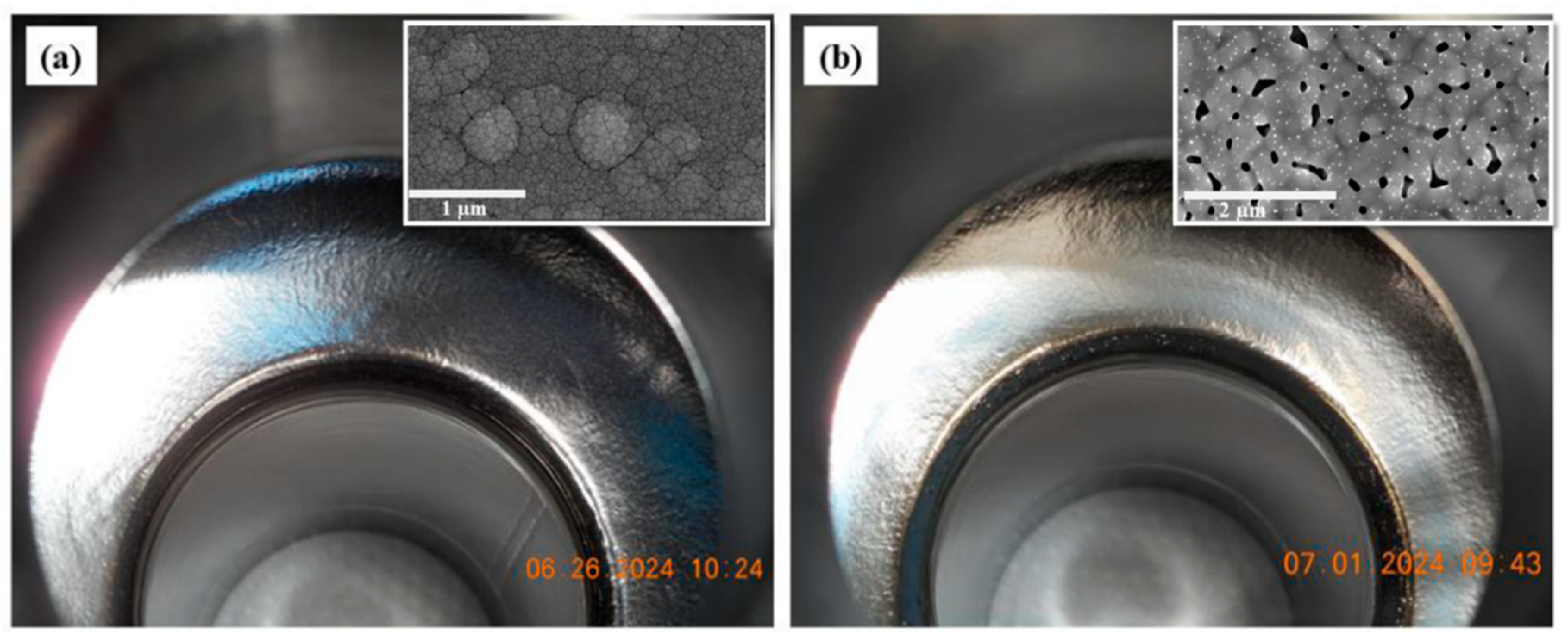
The possibility of using co-sputtering of Nb and Sn onto sapphire substrates was investigated to simplify the process. The crystallinity and Tc of the deposited films at substrate temperatures of room temperature (RT) to 500 °C were dependent on the growth and annealing conditions. Films deposited at 500 °C that were not annealed exhibited a Tc of ~15.0 K, while RT films, after annealing at 665 °C and 950 °C, displayed Tc ≈ 15.9 K and Tc ≈ 17.6 K, respectively. This confirmed that co-sputtering and annealing at higher temperatures produce high-quality Nb3Sn suitable for SRF cavities [92]. The effects of annealing and film thickness on the formation and stability of Nb3Sn coatings were investigated in more detail. Films of thicknesses 100 nm, 300 nm, and 2 µm were deposited by DCMS from a stoichiometric Nb3Sn target onto Nb and Cu substrates. After a 6-h anneal at 600–950 ˚C, thin 100 nm layers on Nb recrystallised well, with Tc ≈ 17.5 K, while thicker 2 µm films lost Sn or did not completely form Nb3Sn, and Cu films decomposed. The findings highlighted that thinner Nb3Sn on Nb substrates are more stable, whereas thicker films and coatings on Cu are less stable [93]. In working towards cavity applications, Shakel et al. developed a co-sputtering process, designed specifically for cylindrical geometries. In this work, using a cylindrical magnetron system, Nb–Sn was sputtered with 32–42 at.% Sn, which crystallized into Nb3Sn after annealing at 950 °C. As shown in Figure 17, a 1.5 µm thick film was successfully deposited on a 2.6 GHz Nb cavity and annealed in two steps (600 °C/6 h and 950 °C/1 h). The resulting coating exhibited Tc ≈ 17.8 K. A light Sn recoating further improved stoichiometry and uniformity, which enhanced RF performance to Q0 ≈ 8.5 × 10⁸ at 2.0 K. This study demonstrated the viability of sputtered Nb3Sn for cavity integration [94].
Figure 17.
Surface of the coated Nb cavity: (a) as deposited and (b) after sequential annealing at 600 °C for 6 h followed by 950 °C for 1 h. Insets show corresponding SEM micrographs of the surface morphology. Reproduced from [94].
Another attempt was made on Cu substrates, where Nb3Sn films of 1.5–2 µm thickness were deposited using DCMS from stoichiometric Nb–Sn targets in Ar or Kr atmospheres. The process gas strongly influenced composition, with Kr increasing the Sn content by ~3 at.% compared to Ar. However, the best performing coatings based on Cu reached Tc ≈ 16 K, interdiffusion between the film and the substrate suppressed Tc by around 2–3 K compared to Nb substrates. The extended annealing to ~750 °C for 24 h improved the ordering of the films and raised Tc [95].
In summary, sputtered Nb3Sn films have achieved Tc values of up to ~17.8 K with microstructures comparable to those of vapour-diffused coatings. The results of these studies indicate that sputtering allows flexibility to control stoichiometry and microstructure. However, Sn deficiency, interdiffusion with Cu, and even strain in thick coatings are still causing reproducibility and stability issues. Therefore, optimisation of deposition and annealing is required before sputtered Nb3Sn can be considered as an alternative to vapour diffusion in real-world applications of SRF cavities.
5.5. Niobium Aluminide (Nb3Al)
Nb3Al as the A15 intermetallic superconductor, with a Tc of almost 18 K and an Hc2 of over 20 T, is very suitable for SRF applications. It has better mechanical toughness and enhanced irradiation resistance than Nb3Sn, which can help relieve thermal and mechanical stress in the SRF cavity. While there are distinct advantages with Nb3Al, the existing research on this material has primarily focused on electronic and device applications with little attention given to its potential for SRF cavities.
Thin films of Nb3Al were first made by magnetron sputtering from arc-melted targets, and reported the highest Tc values for as-sputtered films (up to 16.7 K). The film properties showed a strong dependence on the deposition parameters: well-ordered A15 Nb3Al with a small amount of Nb2Al deposited at 650–700 °C exhibited Tc values above 16 K, but lower temperature deposits displayed disordered structures and low Tc values. Argon pressure also showed a significant influence, as applying less than 10 Pa induced a systematic decrease in Tc, indicating that sufficient thermalisation and reduced substrate bombardment are required to obtain high-Tc Nb3Al films [96]. In later studies, single-phase Nb3Al targets produced from melt-and-cast processing were used for RF magnetron sputtering. Films deposited on sapphire substrates (after annealing the films at ~865 °C) yielded Tc ≈ 13.8 K, while films on MgO substrates exhibited relatively lower Tc. A15 phase was confirmed by structural analysis, and it was demonstrated that substrate choice significantly affects Tc, and sapphire allows for more interfacial ordering than MgO [97]. More recent work introduced DC co-sputtering from separate Nb and Al targets. As-deposited films at 700–830 °C were severely disordered with a Tc of ~12 K due to aluminium segregation and poor nucleation. Rapid thermal annealing at near 1000 °C, improved the film crystallinity and produced a Tc as high as ~15.7 K for ~300 nm films with ~24 at.% Al. The use of a Nb seed layer improved the texture and crystallographic order, which resulted in improved Tc ≈ 15.3 K with sharper diffraction peaks. The superconducting parameters Hc2 (0) ≈ 17.8 T, ξ ≈ 4.3 nm, and λ ≈ 210 nm were also obtained, which are comparable to NbN and NbTiN thin films [98].
In summary, sputtered Nb3Al films have shown competitive superconducting properties with Tc values above 16 K in optimised conditions. However, they are extremely sensitive to stoichiometry, substrate choice, annealing, and secondary phases. Nb3Al is attractive for many reasons, including its high Tc, large Hc2, and mechanical strength; however, there has been no systematic investigation for SRF cavity coatings. This is an under-utilised opportunity for developing SRF thin-film technology.
5.6. Vanadium Silicide (V3Si)
V3Si is an A15-type superconductor with a bulk Tc approaching ~17 K and an Hc2 of over 20 T; therefore, it remains an interesting candidate for SRF. Like the other A15 compounds, V3Si is brittle, creating difficulties when considering its use in bulk applications. However, thin-film deposition through sputtering may allow us to take advantage of its favourable superconducting properties.
Early studies focused on post-deposition annealing of sputtered V films. Upon annealing on silica-based substrates at temperatures between 300–900 °C, the superconducting properties were significantly influenced by temperature and substrate. In the case of deposition on Vycor substrate, Tc was observed to be <1.4 K after annealing at temperatures < 600 °C, but it rose to ~12 K at this threshold and finally rose to ~13 K at 750 °C, prior to some partial flaking occurring at ~900 °C. On quartz, Tc values of 11.1–13.3 K were obtained with an anneal at 725 °C; while on Si, an anneal at 900 °C led to Tc values up to 14.7–16.8 K, gaining bulk-like performance. A film annealed at 800 °C on Vycor had the best upper critical field Hc2 (4.2 K) ≈ 13–17.5 T, which confirms that one can get high-quality V3Si films despite the inherent brittleness of the compound [99]. To overcome substrate constraints and enhance compositional control, V3Si was grown on sapphire by reactive DCMS from V targets in Ar–SiH4 mixtures at ~15 mTorr. Films grown at temperatures above 700 °C obtained the best properties, with Tc ≈ 16.8 K, while V-rich films (with >75 at.% V) exhibited lower Tc (~15 K) due to inhomogeneity from grain-to-grain. While the A15 phase may be able to form below 300 °C, the limited value of Tc (7–9 K) shows both the sensitivity of Tc to growth conditions and the inherent difficulties of achieving stoichiometric uniformity in reactively sputtered V3Si [100]. The following work used stoichiometric V3Si targets and direct sputtering to produce uniform films on substrates relevant to SRF. Films were deposited on Cu and sapphire using pulsed DCMS in Kr at 790 °C with an average thickness of ~1.4 μm. The coatings had a slight Si excess (V:Si ≈ 72:28). All films exhibited a granular structure; films on Cu had small, dense grains relative to those on sapphire. The two samples exhibited superconductivity with Tc ≈ 14.3 K on sapphire and 12.8 K on Cu. The magnetic field at first penetration was Bfp (4.2 K) = 61 mT for sapphire, and Bfp (4.2 K) = 19 mT for Cu. Sapphire performed relatively better than Cu, showing the detrimental effects of Cu interdiffusion [101].
More recently, high-ionisation techniques such as HiPIMS have been employed to improve density and microstructure. V3Si films deposited from stoichiometric targets in Kr (3 × 10⁻³ mbar, 300 W, 1 kHz, 10 µs pulse, 10% duty cycle) exhibited contrasting morphologies depending on the substrate. The sapphire coatings were porously large-grained, while the coatings on Nb had finer crystallites, which were affected by the rougher surface of the substrates (Figure 18a,b). The Tc values were 14.85 K and 13 K for sapphire and Nb, respectively, and both were below the bulk limit, which is attributed to small grain size and contamination during growth [102].
Figure 18.
SEM images of V3Si films deposited by HiPIMS on (a) a sapphire substrate and (b) a Nb substrate. Reproduced from [102].
Further studies added to the understanding of the importance of annealing to produce the A15 phase and relieve strain. Films deposited by DCMS on Nb and Cu substrates and annealed between 600–950 °C exhibited different behaviour. The 2 μm layers on Nb initially had approximately 15% strain, which was relieved during annealing in the range of 800–950 °C, enabling a phase transition to the stable V3Si phase. On Cu, the 300 nm films contained Cu–Si phases due to interdiffusion at 550 °C. An anneal at 950 °C removed the Cu–Si phases but left Cu inclusions and surface-like artefacts that degraded performance in the films. Observation of this study here shows that annealing stabilises V3Si and significantly removes strain in the film on Nb, while noting that Cu substrates require buffer layers for SRF coatings to mitigate interdiffusion [93].
Overall, sputtered V3Si films have demonstrated Tc values up to ~16.8 K and Hc2 exceeding 17 T, showing promise for SRF applications. However, there are still many challenges, including difficulty with stoichiometry control, interdiffusion and inclusion that can arise from substrate interactions. For V3Si to develop as a potential alternative superconductor for SRF cavity coatings, these issues need to be overcome with optimised annealing, buffer-layer engineering, and advanced sputtering methods.
5.7. Mo-Re Alloys
Mo-Re alloys have been investigated as SRF coating materials due to the combination of relatively high Tc with low impurity solubility and desirable RF properties [23]. The ability to stabilise metastable A15 phases in thin films also contributes to their suitability for cavity applications [103].
The first stabilisation of an A15 Mo–Re phase in thin films was achieved via sputtering from composite Mo–Re targets at ~500 °C in ultra-high vacuum. A ~6 μm thick film deposited on sapphire showed superconducting Tc as high as ~15 K, and the transitions were very sharp (ΔTc ≤ 0.5 K). The transitions occurred at ~9 K for Mo0.3Re0.7 (tetragonal phase) and ~13–15 K for Mo0.7Re0.3 (A15 phase), suggesting that phase composition is directly related to Tc. The initial signs of A15 phase stabilisation prompted further studies that sought to optimise deposition temperature for tuning superconducting and RF properties [103]. Andreone et al. used DC magnetron sputtering to deposit Mo75Re25 films on sapphire at 1 × 10⁻³ Torr Ar pressure and substrate temperatures ranging from 100 °C to 900 °C. The films exhibited stoichiometric A15 phase, with Tc ≈ 9–10.3 K, and RRR increased from 1.4 at 100 °C to 2.5 at 900 °C. The calculated BCS surface resistance at 500 MHz and 4.2 K reached a value as low as 10 nΩ, which is still much lower than that of Nb (40 nΩ) [104]. The effects of composition and annealing were then studied in a systematic way. Films of compositions Mo75Re25, Mo60Re40, and Mo38Re62 were deposited by magnetron sputtering at 600–1000 °C and annealed in situ. For Mo75Re25, the highest values of Tc ≈ 11.82 K and exceptionally low ΔTc = 0.012 K were produced by annealing in the range of 751–793 °C (RRR = 1.71). The Mo60Re40 films, annealed at a temperature range between 800–856 °C, produced the highest Tc = 12.13 K (ΔTc = 0.065 K, RRR = 1.3), while the Mo38Re6 films exhibited Tc ≈ 9.47 K. In every case, the improvement in homogeneity, transition sharpness, and Tc was clearly seen across the composition range studied. BCS surface resistance at 500 MHz and 4.2 K was ~16 nΩ for Mo60Re40 and Mo75Re25, which was significantly less than sputtered Nb (~64 nΩ), suggesting that the films to be potentially useful for SRF use [105].
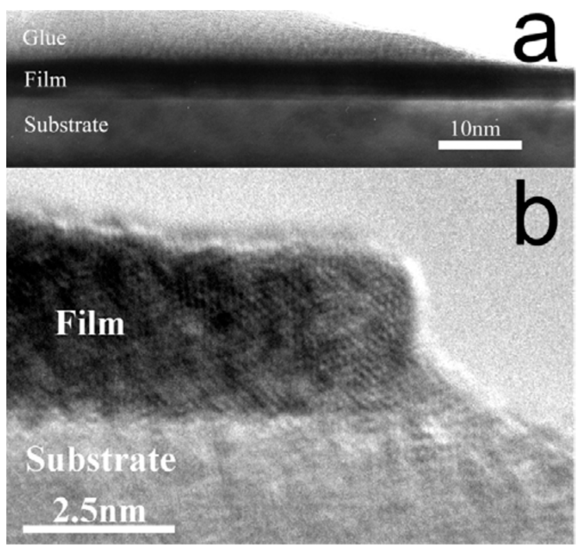
With these studies being mostly focused on bulk-like thick films, subsequent investigations began to focus more on ultrathin Mo–Re layers. Seleznev et al. fabricated 2–10 nm Mo60Re40 films on sapphire by DCMS at 3 × 10⁻³ Torr Ar and with substrate temperatures ranging from 150–600 °C. The films displayed uniform structure, and both stoichiometric transfer was achieved (Mo/Re ≈ 0.575/0.425), albeit with ~10% oxygen contamination. The superconducting temperature was sensitive to thickness and deposition conditions: Tc = 4.2–5.2 K (2 nm), 5.2–7.7 K (4 nm), and 9.7 K (10 nm) with narrow transitions (ΔTc = 0.1–0.3 K). Increasing the substrate temperature improved the film quality, and consequently, the Tc increased 4.75 K at 170 °C to 7.0 K at 380 °C, and then dropped to 6.2 K at 600 °C. HRTEM images indicated that the films possess continuous and homogeneous microstructure throughout the thickness of the films, without any breaks or exfoliation (Figure 19a,b) [106].
Figure 19.
Cross-sectional HRTEM image of a 4 nm Mo60Re40 film (a) Low-magnification view showing the continuous film, substrate, and glue layer. (b) High-resolution view of the film–substrate interface, confirming a homogeneous structure without breaks or exfoliations. Reproduced from [106].
Overall, sputtered Mo–Re films show excellent superconducting and RF properties, including Tc ≈ 15 K in thick films and ~10 K in ultrathin layers, and calculated surface resistances are much lower than Nb, emphasising their use for SRF. Further understanding of controlling stoichiometry, thickness, and impurity incorporation (especially oxygen), will be key to unlocking the potential of Mo–Re as an SRF coating material, both in bulk-like films and multilayer cavity concepts.
5.8. Magnesium Diboride (MgB2)
MgB2 was discovered in 2001, with a Tc of ~39 K [107]. The crystal structure of MgB2 is hexagonal, with all boron layers in a closed-packed arrangement separated by the magnesium layers. Unlike the majority of superconductors, MgB2 shows a novel two-gap behaviour with Δπ ≈ 2.7 meV and Δσ ≈ 6.7 meV [108]. It is a promising candidate for SRF cavities in the 15–20 K range because of its relatively high Tc, moderate Hc2, and extremely low resistivity in the normal state (≤1 μΩ·cm) [23]. However, the application of MgB2 thin films for SRF cavities is limited by several drawbacks, including the high volatility of Mg, difficulties in depositing dense and stoichiometric films, and a very high sensitivity to oxygen contamination [109].
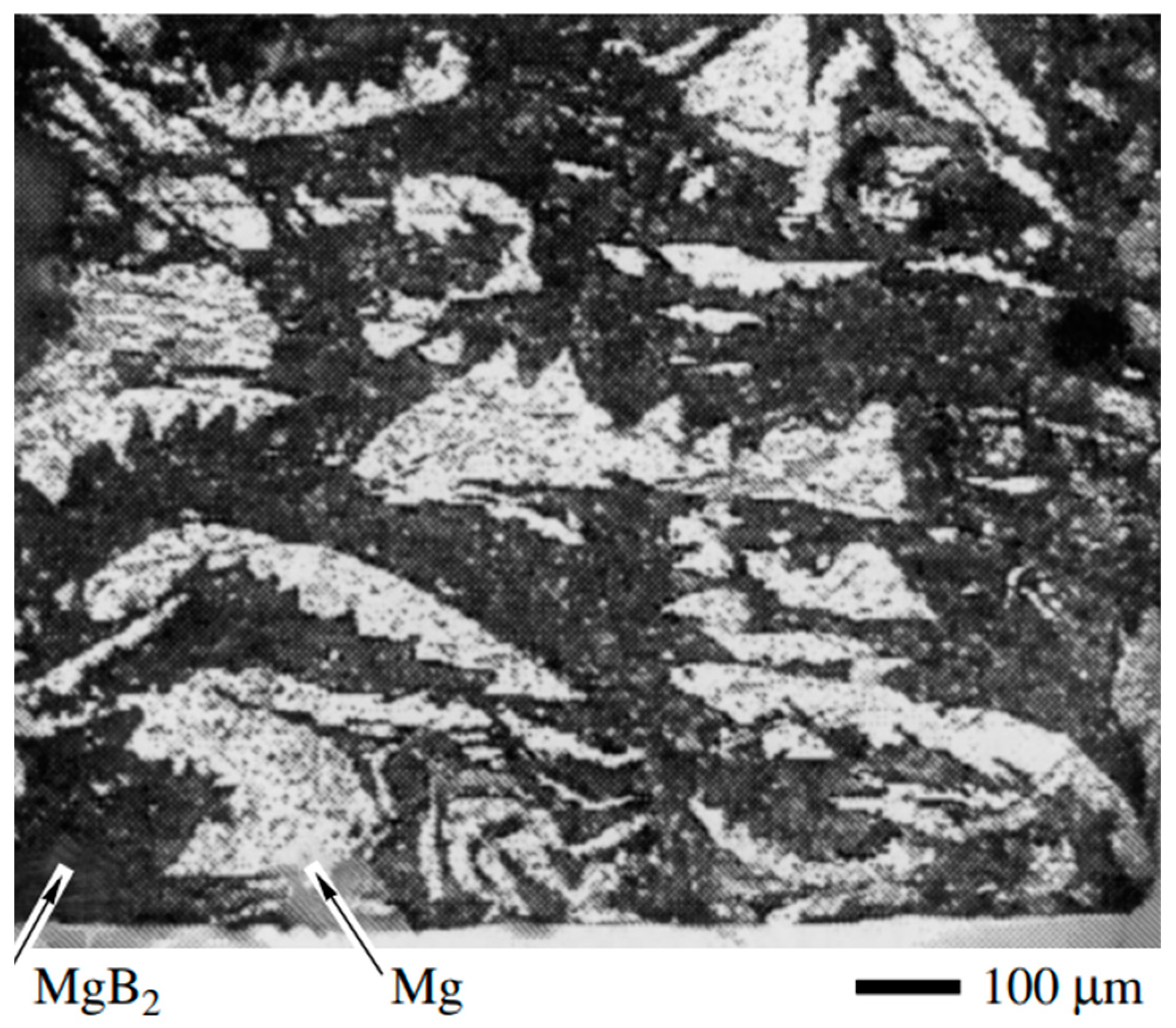
In the first demonstration of MgB2 thin films using DCMS, a composite MgB2–Mg (∅32 mm) target was used. The target was particularly made to mitigate losses of Mg during the oxidation of plasma. The dense structure of the target enabled good heat transfer, stable sputtering, and prevented target cracking even at higher power densities. A cross-sectional fragment of the composite target (Figure 20) shows that the black regions correspond to the MgB2 and the white areas to metallic Mg. Films were deposited on sapphire with high-purity Ar (3 Pa, ~120 W/cm2) at 200 °C and were followed by a short in situ annealing at 600 °C. The obtained films were fine-grained and uniform in morphology with Tc ≈ 24 K. Although the morphology was promising, the measured resistivity was over two orders of magnitude, greater than that of bulk MgB2, which is attributed to the small grain size [107].
Figure 20.
Cross-sectional fragment of the composite Mg–MgB2target, where the black regions correspond to MgB2 and the white areas to metallic Mg. Reproduced from [107].
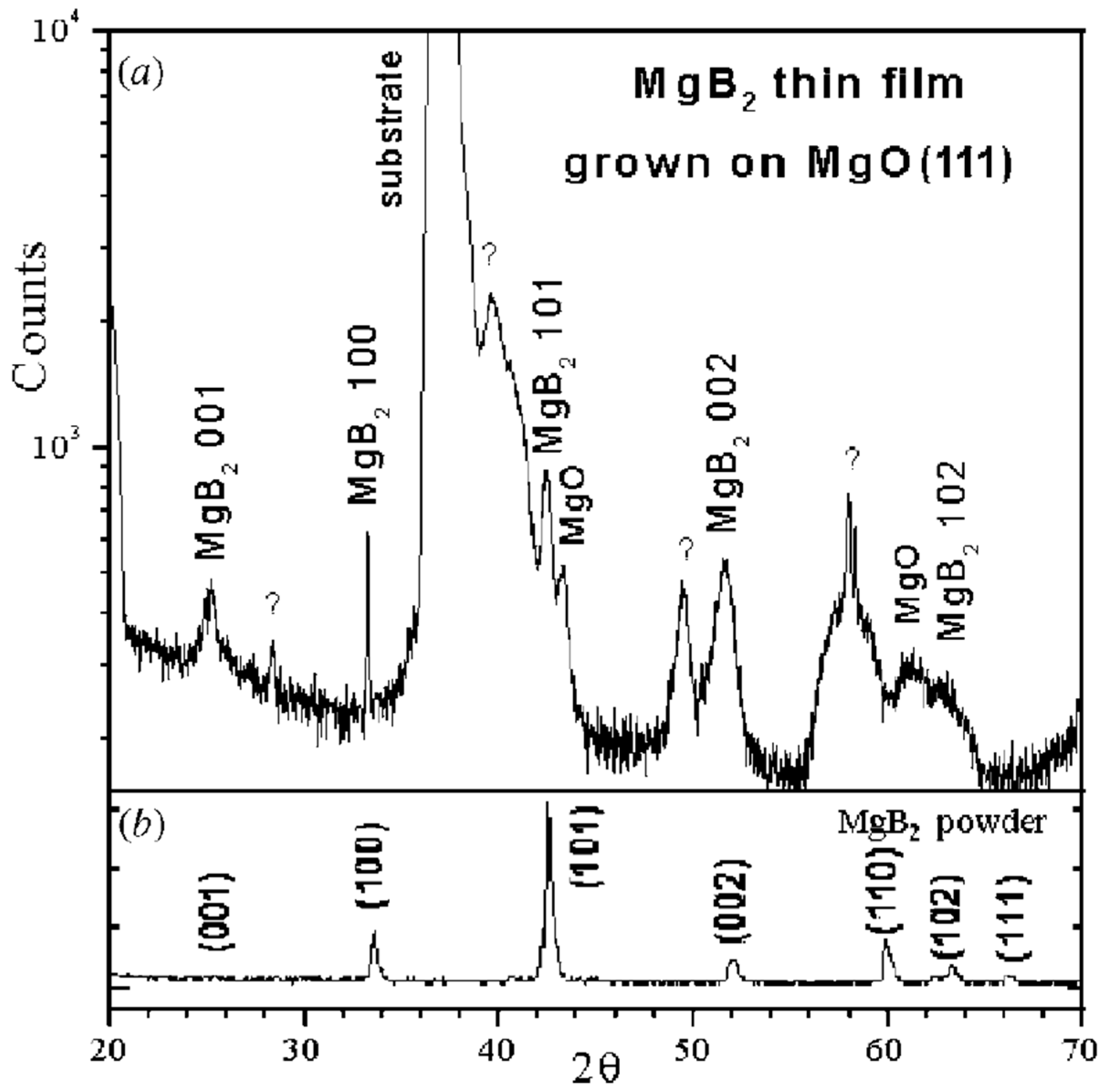
While this pioneering work demonstrated the feasibility of sputtering MgB2, subsequent attempts quickly revealed how severe Mg volatility can be in destabilising film stoichiometry. MgB2 thin films were sputtered from compacted powder targets (3 mm) at 4 × 10⁻³ mbar Ar, 5 sccm flow, using 25 W pulsed DC power for 4 h. The films were dense, pore-free, and adherent; however, the Mg/B atomic ratio was lower than the desired 1:2 stoichiometry, which is explained by the high volatility of Mg relative to B. As a result, no superconductivity was observed. It was suggested that this limitation could be overcome by introducing a Mg overpressure during deposition and by using lower sputtering powers to reduce heat generation and hence the rate of Mg vaporisation [110]. Recognising these limitations, other groups studied co-deposition routes combined with post-annealing to control stoichiometry. Mičunek et al. prepared MgB2 thin films on sapphire substrates by co-deposition of boron (RF magnetron, 250 W) and magnesium (DC magnetron, 29 W) at a working Ar pressure of 7.4 × 10⁻² Pa, directly on unheated sapphire substrates, followed by ex situ annealing in Ar. Following 40 min of deposition, a ~200 nm Mg-B precursor film was produced, which was then annealed at 620–680 °C. The best results were obtained at 680 °C for 2.5 min, where the films showed an onset Tc of ≤35 K. However, Auger analysis indicated that excess magnesium and contamination from oxygen decreased the performance of the film [111]. With the development of Mg vapour-assisted sputtering, a major milestone was achieved with regard to film quality and reproducibility. In this method, a two-step in situ DCMS process was used to deposit Mg–B precursor layers in high-purity Ar (9 × 10⁻¹ Pa) from MgB2 and Mg targets, followed by annealing at 830 °C for 10 min inside a sealed Nb box under Mg vapour. This novel approach provided a saturated Mg vapour environment that improved the film quality and reproducibility. The XRD pattern (Figure 21) for a film deposited on crystalline MgO (111) confirmed the MgB2 phase with small amounts of MgO (from oxidation of excess Mg) and minor unidentified phases. AFM showed a granular surface with columnar grains a few microns wide and ~50 nm roughness. The films (~0.8–1 µm) on sapphire and MgO substrates exhibited Tc ≈ 35 K with a narrow ΔTc ≈ 0.5 K, RRR ≈ 1.6, room-temperature resistivity ~200 µΩ·cm, and upper critical fields of Hc2⊥ ≈ 2.9 T and Hc2‖ ≈ 8 T at 25.7 K. This work represented one of the first demonstrations of high-quality in situ sputtered MgB2 films without ex situ annealing [7].
Figure 21.
(a) XRD spectrum of a MgB2 film deposited on a MgO(111) substrate, showing MgB2 phase formation with minor MgO and unidentified phases. (b) Reference XRD pattern of MgB2 powder for comparison. Adapted from Vaglio et al. [7].
While improvements have been made, MgB2 films fabricated by sputtering remain considerably short of their bulk potential. Other deposition techniques, such as low-pressure CVD, pulsed laser deposition, and molecular beam epitaxy, produce higher quality MgB2 films, and sputtered MgB2 continues to have difficulties with challenges of Mg volatility, oxygen inclusion, and microstructural inhomogeneities. Further optimisation of Mg overpressure, substrate heating and contamination control is required before MgB2 can be a viable coating option for SRF cavities. If these challenges can be overcome, MgB2 may allow SRF operation at 15–20 K, an important milestone for cost-effective accelerators.
6. Conclusions and Outlook
Over the last few decades, sputtered Nb has demonstrated superior performance in SRF cavity applications, with accelerating gradients exceeding 20 MV/m and quality factors of ~109. However, its performance remains limited by voids, impurities, non-uniformity, and adhesion issues. NbN and NbTiN have proven to be valuable candidates, particularly for SIS multilayer structures that have achieved superior magnetic screening and delayed flux penetration beyond that of bulk Nb. Among the A15 compounds, Nb3Sn thin films remain the most optimised; however, Sn deficiency and Cu interdiffusion remain challenging. Other materials, such as Nb3Al, V3Si, and Mo-Re, are still at an exploratory stage; MgB2 has the highest Tc, allowing SRF operation to be performed at 15–20 K; nevertheless, it suffers from instability and high oxygen sensitivity. Overall, these studies show that while Nb remains the benchmark, sputtered nitrides, A15 compounds, and MgB2 provide key strategies for improving SRF thin-film technologies. Sputtering has established itself as the most versatile route for depositing superconducting thin films for SRF cavities. Across all material systems, dense, stoichiometric, uniform and adherent films have consistently higher Tc, lower Rs, and greater RF stability. Advances in the future can be made through three approaches: (i) energetic sputtering (i.e., HiPIMS) for dense homogeneous films, (ii) multilayer or interface engineering to exceed the fundamental limits of Nb, and (iii) systematic cavity demonstrations. If these advances are realised, sputtered films could become true high-performance SRF coatings for next-generation accelerators.
Author Contributions
B.R.L.R.V. conducted the literature review and wrote the manuscript. A.Z. contributed to writing and editing. X.J. contributed to writing and editing. All authors have read and agreed to the published version of the manuscript.
Funding
This research was funded by the Bundesministerium für Bildung und Forschung (BMBF)/Deutsches Elektronen-Synchrotron (DESY) under the collaborative project NOVALIS (NOVel ACcelerator technology for efficient LIght Sources- 05K22PSB).
Data Availability Statement
No new data were created or analyzed in this study.
Acknowledgments
We used Grammarly (https://app.grammarly.com/) to support grammar and language editing during the preparation of this review. All suggestions were carefully evaluated and revised by the authors, who take full responsibility for the final content of this paper.
Conflicts of Interest
The authors declare that they have no conflicts of interest.
References
- Simon, N.; Drexler, E.; Reed, R. Properties of Copper and Copper Alloys at Cryogenic Temperatures. 1992. Available online: https://www.osti.gov/biblio/5340308 (accessed on 17 July 2025).
- Padamsee, H. Superconducting Radiofrequency Technology for Accelerators: State of Art and Emerging Trends; Wiley-VCH: Weinheim, Germany, 2023. [Google Scholar]
- Singer, W. Fabrication of elliptical SRF cavities. Supercond. Sci. Technol. 2017, 30, 33001. [Google Scholar] [CrossRef]
- Hryhorenko, O.; Antoine, C.Z.; Magnin, W.; Rajkumar, M.; Brisset, F.; Guilet, S.; Longuevergne, D. An Innovative Approach of Surface Polishing for SRF Cavity Applications. JMMP 2023, 7, 62. [Google Scholar] [CrossRef]
- Padamsee, H.; Seaman, A.K.; Shemelin, V.D. World Record Accelerating Gradient Achieved in a Superconducting Niobium RF Cavity. In Proceedings of the 2005 Particle Accelerator Conference, Knoxville, TN, USA, 16–20 May 2005. [Google Scholar]
- Nagata, T.; Masui, H.; Shinozawa, S.; Inoue, H.; Kako, E.; Yamanaka, M.; Murakami, M. Development of High Purity Niobium Components and Cavities for SRF Accelerator. In Proceedings of the 18th International Conference on RF Superconductivity (SRF′17), Lanzhou, China, 17–21 July 2017; JACoW: Geneva, Switzerland, 2018. [Google Scholar] [CrossRef]
- Vaglio, R. Alternative Superconducting Materials for RF Cavity Applications. In Proceedings of the 1997 Workshop on RF Superconductivity, Padova, Italy, 6–10 October 1997. [Google Scholar]
- Ge, G.M.; Eichhorn, R.G.; Elmore, B.; Furuta, F.; Gonnella, D.; Gruber, T.; Hoffstaetter, G.H.; Kaufman, J.J.; Liepe, M.; O’Connell, T.I.; et al. Performance of nitrogen-doped 9-cell srf cavities in vertical tests at Cornell University. In Proceedings of the SRF2015, Whistler, BC, Canada, 13–18 September 2015. [Google Scholar]
- Kelly, M.P.; Reid, T. Surface processing for bulk niobium superconducting radio frequency cavities. Supercond. Sci. Technol. 2017, 30, 43001. [Google Scholar] [CrossRef]
- Dhakal, P. Nitrogen doping and infusion in SRF cavities: A review. Phys. Open 2020, 5, 100034. [Google Scholar] [CrossRef]
- Terrazas, C.A.; Mireles, J.; Gaytan, S.M.; Morton, P.A.; Hinojos, A.; Frigola, P.; Wicker, R.B. Fabrication and characterization of high-purity niobium using electron beam melting additive manufacturing technology. Int. J. Adv. Manuf. Technol. 2015, 84, 1115–1126. [Google Scholar] [CrossRef]
- Lilje, L. State of the Art SRF Cavity Performance. In Proceedings of the LINAC 2004, Luebeck, Germany, 16–20 August 2004. [Google Scholar]
- Maxfield, B.W.; McLean, W.L. Superconducting Penetration Depth of Niobium. Phys. Rev. 1965, 139, A1515–A1522. [Google Scholar] [CrossRef]
- Kubo, S.; Asahi, M.; Hikita, M.; Igarashi, M. Magnetic penetration depths in superconducting NbN films prepared by reactive dc magnetron sputtering. Appl. Phys. Lett. 1984, 44, 258–260. [Google Scholar] [CrossRef]
- Tückmantel, J. The LEP2 Superconducting RF System CERN-SL-98-051-RF. 1998. Available online: https://cds.cern.ch/record/365878 (accessed on 15 July 2025).
- About HIE-ISOLDE|HIE-ISOLDE. Available online: https://hie-isolde-project.web.cern.ch/node/35217.html (accessed on 1 September 2025).
- CERN. The Large Hadron Collider. Available online: https://home.cern/science/accelerators/large-hadron-collider (accessed on 1 September 2025).
- Calatroni, S. 20 Years of experience with the Nb/Cu technology for superconducting cavities and perspectives for future developments. Phys. C Supercond. 2006, 441, 95–101. [Google Scholar] [CrossRef]
- Posen, S.; Liepe, M. SRF Cavities Beyond Niobium: Challenges and Potential. In Proceedings of the 2013 PAC, Pasadena, CA USA, 29 September–4 October 2013. [Google Scholar]
- Palmieri, V.; Vaglio, R. Thermal contact resistance at the Nb/Cu interface as a limiting factor for sputtered thin film RF superconducting cavities. Supercond. Sci. Technol. 2016, 29, 15004. [Google Scholar] [CrossRef]
- Ngampruetikorn, V.; Sauls, J.A. Effect of inhomogeneous surface disorder on the superheating field of superconducting RF cavities. Phys. Rev. Res. 2019, 1, 12015. [Google Scholar] [CrossRef]
- Gurevich, A.; Kubo, T.; Sauls, J.A. Challenges and opportunities of srf theory for next generation particle accelerators. arXiv 2022, arXiv:2203.08315. [Google Scholar] [CrossRef]
- Valente-Feliciano, A.-M. Superconducting RF materials other than bulk niobium: A review. Supercond. Sci. Technol. 2016, 29, 113002. [Google Scholar] [CrossRef]
- Gurevich, A. Enhancement of rf breakdown field of superconductors by multilayer coating. Appl. Phys. Lett. 2006, 88, 012511. [Google Scholar] [CrossRef]
- Burton, M.C.; Beebe, M.; Lukaszew, R.A.; Riso, J.M. Superconducting NbN-Based Multilayer and NbTiN Thin Films for the Enhancement of SRF Accelerator Cavities. In Proceedings of the SRF2015, Whistler, BC, Canada, 13–18 September 2015. [Google Scholar]
- Katayama, R.; Hayano, H.; Kubo, T.; Saeki, T.; Ito, H.; Iwashita, Y.; Tongu, H.; Antoine, C.Z.; Ito, R.; Nagata, T. Evaluation of the superconducting characteristics of multi-layer thin-film structures of NbN and SiO2 on pure Nb substrate. arXiv 2019, arXiv:1907.03514. [Google Scholar] [CrossRef]
- Ito, H.; Hayano, H.; Kubo, T.; Saeki, T.; Katayama, R.; Iwashita, Y.; Tongu, H.; Ito, R.; Nagata, T.; Antoine, C.Z. Lower critical field measurement of NbN multilayer thin film superconductor at KEK. arXiv 2019, arXiv:1907.03410. [Google Scholar] [CrossRef]
- Valente, A.; Eremeev, G.; Phillips, H.; Reece, C.; Spradlin, J.; Yang, Q.; Lukaszew, R. NbTiN Based SIS Multilayer Structures for SRF Applications; JLAB-ACC-13-1716; DOE/OR/23177-2844; Thomas Jefferson National Accelerator Facility (TJNAF): Newport News, VA, USA, 2013. Available online: https://www.osti.gov/biblio/1164412 (accessed on 1 June 2025).
- Sharma, R.G. A Review of Theories of Superconductivity. Superconductivity 2021, 214, 123–160. [Google Scholar] [CrossRef]
- Hott, R.; Kleiner, R.; Wolf, T.; Zwicknagl, G. Review on Superconducting Materials. arXiv 2013, arXiv:1306.0429. [Google Scholar] [CrossRef]
- Fossheim, K.; Sudbø, A. Superconductivity; Wiley: Hoboken, NJ, USA, 2004. [Google Scholar]
- Onnes, H.K. Comm. Leiden Nr. 108. Proc. Roy. Acad. Amst. 1908, 108. Available online: https://dwc.knaw.nl/DL/publications/PU00013525.pdf (accessed on 1 September 2025).
- Meissner, W.; Ochsenfeld, R. Ein neuer Effekt bei Eintritt der Supraleitfhigkeit. Naturwissenschaften 1933, 21, 787–788. [Google Scholar] [CrossRef]
- Deaver, B.S.; Fairbank, W.M. Experimental Evidence for Quantized Flux in Superconducting Cylinders. Phys. Rev. Lett. 1961, 7, 43–46. [Google Scholar] [CrossRef]
- Kittel, C. Introduction to Solid State Physics, 8th ed.; Wiley: Hoboken, NJ, USA, 2005. [Google Scholar]
- Beringer, D. T01-Thin Film Approaches to the Srf Cavity Problem: Fabrication and Characterization of Superconducting Thin Films. Ph.D. Thesis, The College of William and Mary, Williamsburg, VA, USA, 2016. [Google Scholar]
- Gorter, C.; Casimir, H. On supraconductivity I. Physica 1934, 1, 306–320. [Google Scholar] [CrossRef]
- London, F.; London, H. The electromagnetic equations of the supraconductor. Proc. R. Soc. Lond. A 1935, 149, 71–88. [Google Scholar] [CrossRef]
- Ginzburg, V.L.; Landau, L.D. On the Theory of Superconductivity. Zhurnal Eksperimental’noi I Teor. Fiz. 1950, 20, 1064–1082. [Google Scholar]
- Bardeen, J.; Cooper, L.N.; Schrieffer, J.R. Theory of Superconductivity. Phys. Rev. 1957, 108, 1175–1204. [Google Scholar] [CrossRef]
- Padamsee, H. RF Superconductivity: Science, Technology, and Applications; Wiley-VCH: Weinheim, Germany, 2009. [Google Scholar]
- Burton, M.C.; Palczewski, A.D.; Phillips, H.L.; Reece, C.E.; Valente-Feliciano, A.-M.; Lukaszew, R.A. RF Results of Nb Coated SRF Accelerator Cavities via HiPIMS. In Proceedings of the LINAC2018, Beijing, China, 16–21 September 2018; JACoW Publishing: Geneva, Switzerland, 2018. [Google Scholar] [CrossRef]
- Romanenko, A.; Grassellino, A.; Barkov, F.; Ozelis, J.P. Effect of mild baking on superconducting niobium cavities investigated by sequential nanoremoval. Phys. Rev. ST Accel. Beams 2013, 16, 12001. [Google Scholar] [CrossRef]
- Bayros, K.; Cyster, M.J.; Smith, J.S.; Cole, J.H. Influence of pinholes and weak-points in aluminum-oxide Josephson junctions. Phys. Rev. Mater. 2024, 8, 46202. [Google Scholar] [CrossRef]
- Senevirathne, I.H.; Beverstock, D.R.; Valente-Feliciano, A.-M.; Gurevich, A.V.; Delayen, J.R.; Beverstock, D.R. Investigation of the Multilayer Shielding Effect Through NbTiN-AIN Investigation of the Multilayer Shielding Effect Through NbTiN-AIN Coated Bulk Niobium Coated Bulk Niobium. In Proceedings of the 21st International Conference on RF Superconductivity, Grand Rapids, MI, USA, 25–30 June 2023. [Google Scholar]
- Subrahmanyam, A. Plasma Overview and the Basics of Cold Plasma. Material Synthesis. In Cold Plasma in Nano-Matter Synthesis; Springer: Cham, Switzerland, 2024; pp. 27–101. ISBN 978-3-031-64041-4. [Google Scholar]
- Wasa, K.; Kanno, I.; Kotera, H. Handbook of Sputter Deposition Technology: Fundamentals and Applications for Functional Thin Films, Nanomaterials and MEMS, 2nd ed.; William Andrew: Waltham, MA, USA, 2012. [Google Scholar]
- Ohring, M. Materials Science of Thin Films: Deposition and Structure, 2nd ed.; Academic Press: San Diego CA, USA, 2002. [Google Scholar]
- Lundin, D.; Minea, T.; Gudmundsson, J.T. High Power Impulse Magnetron Sputtering: Fundamentals, Technologies, Challenges and Applications; Elsevier Science: Amsterdam, The Netherlands, 2019; ISBN 9780128124543. [Google Scholar]
- Bandorf, R.; Sittinger, V.; Bräuer, G. High Power Impulse Magnetron Sputtering—HIPIMS. In Comprehensive Materials Processing; Hashmi, S., Batalha, G.F., van Tyne, C.J., Yilbas, B., Eds.; Elsevier: Oxford, UK, 2014; pp. 75–99. ISBN 978-0-08-096533-8. [Google Scholar]
- Borowski, P.; Myśliwiec, J. Recent Advances in Magnetron Sputtering: From Fundamentals to Industrial Applications. Coatings 2025, 15, 922. [Google Scholar] [CrossRef]
- Sublet, A.; Venturini Delsolaro, W.; Therasse, M.; Bartova, B.; Calatroni, S.; Jecklin, N.; Zhang, P.; Cantoni, M.; Aviles Santillana, I.; Mondino, I. Nb Coated HIE-ISOLDE QWR Superconducting Accelerating Cavities: From Process Development to Series Production. In Proceedings of the IPAC2014, Dresden, Germany, 15–20 June 2014. [Google Scholar]
- Junginger, T.; Calatroni, S.; Sublet, A.; Terenziani, G.; Prokscha, T.; Salman, Z.; Suter, A.; Proslier, T.; Zasadzinski, J. A low energy muon spin rotation and point contact tunneling study of niobium films prepared for superconducting cavities. Supercond. Sci. Technol. 2017, 30, 125013. [Google Scholar] [CrossRef]
- Baptista, A.; Silva, F.; Porteiro, J.; Míguez, J.; Pinto, G. Sputtering Physical Vapour Deposition (PVD) Coatings: A Critical Review on Process Improvement and Market Trend Demands. Coatings 2018, 8, 402. [Google Scholar] [CrossRef]
- Strenzke, V.; Weber, A.; Heydolph, P.; Moch, I.; González Díaz-Palacio, I.; Hillert, W.; Zierold, R.; Tiemann, L.; Blick, R.H. Challenges and solutions in RF sputtering of superconducting Nb for nanostructuring processes. J. Appl. Phys. 2024, 136, 205301. [Google Scholar] [CrossRef]
- Logan, J.S.R.F. diode sputtering. Thin Solid Film. 1990, 188, 307–321. [Google Scholar] [CrossRef]
- Kelly, P.; Arnell, R. Magnetron sputtering: A review of recent developments and applications. Vacuum 2000, 56, 159–172. [Google Scholar] [CrossRef]
- Keil, E. Status of LEP2 and LHC. AIP Conf. Proc. 1997, 397, 113–127. [Google Scholar] [CrossRef]
- Gudmundsson, J.T.; Lundin, D. Introduction to magnetron sputtering. In High Power Impulse Magnetron Sputtering; Elsevier: Amsterdam, The Netherlands, 2020; pp. 1–48. [Google Scholar]
- Karthikeyan, S.; Hill, A.E.; Cowpe, J.S.; Pilkington, R.D. The influence of operating parameters on pulsed D.C. magnetron sputtering plasma. Vacuum 2010, 85, 634–638. [Google Scholar] [CrossRef]
- Musson, J.; Elsayed-Ali, H.E. Commissioning of a modulated pulse-power magnetron sputtering system for depositing niobium thin films. Vacuum 2024, 229, 113547. [Google Scholar] [CrossRef]
- Awais, A.; Lunt, A.; Sublet, A.; Rosaz, G.; Taborelli, M. Double Cathode Configuration for the Nb Coating of HIE-ISOLDE Cavities. In Proceedings of the SRF2017, Lanzhou, China, 17–21 July 2017; Joint Accelerator Conferences Website (JACoW): Geneva, Switzerland, 2018; pp. 854–858. [Google Scholar]
- Gudmundsson, J.T.; Brenning, N.; Lundin, D.; Helmersson, U. High power impulse magnetron sputtering discharge. J. Vac. Sci. Technol. A Vac. Surf. Film. 2012, 30, 030801. [Google Scholar] [CrossRef]
- Anders, A. Tutorial: Reactive high power impulse magnetron sputtering (R-HiPIMS). J. Appl. Phys. 2017, 121, 171101. [Google Scholar] [CrossRef]
- Reddy, L.R.V.B.; Zubtsovskii, A.; Jiang, X. Effects of deposition parameters on superconducting NbTiN thin films for use in SRF multilayer structures. In Proceedings of the 11th International Workshop on Thin Films and New Ideas for Pushing the Limits of RF Superconductivity-TFSRF2024, Paris, France, 16–20 September 2024; NOVel Accelerator technology for efficient LIght Sources (NOVALIS): Darmstadt, Germany, 2023. [Google Scholar]
- Roach, W.M.; Beringer, D.B.; Skuza, J.R.; Oliver, W.A.; Clavero, C.; Reece, C.E.; Lukaszew, R.A. Niobium thin film deposition studies on copper surfaces for superconducting radio frequency cavity applications. Phys. Rev. ST Accel. Beams 2012, 15, 062002. [Google Scholar] [CrossRef]
- Wilde, S.; Valizadeh, R.; Malyshev, O.B.; Stenning, G.B.G.; Sian, T.; Chesca, B. dc magnetometry of niobium thin film superconductors deposited using high power impulse magnetron sputtering. Phys. Rev. Accel. Beams 2018, 21, 073101. [Google Scholar] [CrossRef]
- Leith, S.; Qiao, J.; Vogel, M.; Seiler, E.; Ries, R.; Li, Y.; Wiktor, C.; Mueller, J.; Sakalli, Y.; Butz, B.; et al. HiPIMS deposition of superconducting Nb thin films onto Cu substrates. Vacuum 2023, 212, 112041. [Google Scholar] [CrossRef]
- Leith, S.; Vogel, M.; Fan, J.; Seiler, E.; Ries, R.; Jiang, X. Superconducting NbN thin films for use in superconducting radio frequency cavities. Supercond. Sci. Technol. 2021, 34, 25006. [Google Scholar] [CrossRef]
- Rao, P.N.; Swami, M.K.; Ghosh, A.; Jangir, R.; Rai, S.K. Influence of deposition pressure on microstructure, mechanical and electrical properties of niobium thin films. Thin Solid Film. 2024, 805, 140503. [Google Scholar] [CrossRef]
- Rao, P.N.; Swami, M.K.; Ghosh, A.; Jangir, R.; Rai, S.K. Studies on magnetron sputtered niobium thin films: Influence of deposition angle of sputtered atoms. Appl. Phys. A 2025, 131, 168. [Google Scholar] [CrossRef]
- Carlos, C.P.; Leith, S.; Rosaz, G.; Pfeiffer, S.; Senatore, C. Planar deposition of Nb thin films by HiPIMS for superconducting radiofrequency applications. Vacuum 2024, 227, 113354. [Google Scholar] [CrossRef]
- Yang, Y.; Lu, X.; Tan, W.; Xiao, L.; Zhu, L.; Xie, D. Study on laser annealing of niobium films deposited on copper for RF superconducting cavities. Nucl. Instrum. Methods Phys. Res. Sect. A Accel. Spectrometers Detect. Assoc. Equip. 2020, 964, 163803. [Google Scholar] [CrossRef]
- He, P.; Dai, J.; Duan, H.; Kan, J.; Ma, Y.; Xin, T.; Yang, Y.; Zhang, P. Preparation and Characterization of Nb Films Deposited in SRF Cavity via HiPIMS. In Effects of Deposition Parameters on Superconducting NbTiN Thin Films for Use in SRF Multilayer Structures. Proceedings of the 21th International Conference on RF Superconductivity (SRF’23), Grand Rapids, MI, USA, 25–30 June 2023; JACOW Publishing: Geneva, Switzerland, 2023; pp. 651–654. ISBN 2673-5504. [Google Scholar]
- Abdisatarov, B.; Eremeev, G.; Elsayed-Ali, H.E.; Bafia, D.; Murthy, A.; Sung, Z.; Netepenko, A.; Romanenko, A.; Carlos, C.P.A.; Rosaz, G.J.; et al. Optimizing superconducting Nb film cavities by mitigating medium-field Q -slope through annealing. Supercond. Sci. Technol. 2025, 38, 75006. [Google Scholar] [CrossRef]
- Bafia, D.; Grassellino, A.; Melnychuk, O.; Romanenko, A.; Sung, Z.-H.; Zasadzinski, J. Gradients of 50 MV/m in TESLA Shaped Cavities via Modified Low Temperature Bake. In Proceedings of the SRF2019, Dresden, Germany, 30 June–5 July 2019; JACoW Publishing: Geneva, Switzerland, 2019. [Google Scholar]
- Isagawa, S. rf superconducting properties of reactively sputtered NbN. J. Appl. Phys. 1981, 52, 921–927. [Google Scholar] [CrossRef]
- Ryohei, I.T. Development of NbN Film for next-generation superconducting acceleration cavities. In Proceedings of the 2019 Particle Accelerator Conference, Melbourne, Australia, 19–24 May 2019. [Google Scholar]
- Wilde, S.; Alves, E.; Barradas, N.; Chesca, B.; Hannah, A.; Malyshev, O.; Pattalwar, S.; Stenning, G.; Valizadeh, R. High Power Impulse Magnetron Sputtering of Thin Films for Superconducting RF Cavities. In Proceedings of the 17th International Conference on RF Superconductivity (SRF2015), Whistler, BC, Canada, 13–18 September 2015; JACoW: Geneva, Switzerland, 2015. [Google Scholar]
- Kalal, S.; Gupta, M.; Rawat, R. N concentration effects on structure and superconductivity of NbN thin films. J. Alloys Compd. 2021, 851, 155925. [Google Scholar] [CrossRef]
- Beebe, M.R.; Beringer, D.B.; Burton, M.C.; Yang, K.; Lukaszew, R.A. Stoichiometry and thickness dependence of superconducting properties of niobium nitride thin films. J. Vac. Sci. Technol. A Vac. Surf. Film. 2016, 34, 155925. [Google Scholar] [CrossRef]
- Di Leo, R. Niboium-titanium nitride thin films for superconducting rf accelerator cavities. J. Low Temp. Phys. 1989, 78, 41–50. [Google Scholar] [CrossRef]
- Bosland, P.; Cantacuzene, S.; Gobin, J.; Juillard, M.; Martignac, J. NbTiN Thin Films for RF Applications. In Proceedings of the Sixth Workshop on RF Superconductivity, CEBAF, Newport News, VA, USA, 4–8 October 1993. [Google Scholar]
- Marino, M. Study of NbTiN Coatings by Reactive Magnetron Sputtering for the Production of 1.5 GHz Superconducting Accelerating Cavities. In Proceedings of the Workshop on RF Superconductivity, Padua, Italy, 6–10 October 1997. [Google Scholar]
- Yu, L.; Singh, R.K.; Liu, H.; Wu, S.Y.; Hu, R.; Durand, D.; Bulman, J.; Rowell, J.M.; Newman, N. Fabrication of Niobium Titanium Nitride Thin Films with High Superconducting Transition Temperatures and Short Penetration Lengths. IEEE Trans. Appl. Supercond. 2005, 15, 44–48. [Google Scholar] [CrossRef]
- Valente-Feliciano, A.-M.; Eremeev, G.V.; Reece, C.E.; Spradlin, J.K. Growth and Characterization of Multi-Layer NbTiN Films. In Proceedings of the SRF2015, Whistler, BC, Canada, 13–18 September 2015. [Google Scholar]
- Burton, M.C.; Beebe, M.R.; Yang, K.; Lukaszew, R.A.; Valente-Feliciano, A.-M.; Reece, C. Superconducting NbTiN thin films for superconducting radio frequency accelerator cavity applications. J. Vac. Sci. Technol. 2016, 34, 021518. [Google Scholar] [CrossRef]
- Ge, H.; Jin, Y.-R.; Song, X.-H. High quality NbTiN films fabrication and rapid thermal annealing investigation. Chin. Phys. B 2019, 28, 77402. [Google Scholar] [CrossRef]
- Pratap, P.; Nanda, L.; Senapati, K.; Aloysius, R.P.; Achanta, V. Optimization of the superconducting properties of NbTiN thin films by variation of the N2 partial pressure during sputter deposition. Supercond. Sci. Technol. 2023, 36, 85017. [Google Scholar] [CrossRef]
- Sayeed, M.N.; Elsayed-Ali, H.; Eremeev, G.V.; Kelley, M.J.; Pudasaini, U.; Reece, C.E. Magnetron Sputtering of Nb3Sn for SRF Cavities. In Proceedings of the 9th International Particle Accelerator Conference, Vancouver, BC, Canada, 29 April–4 May 2018; JACoW Publishing: Geneva, Switzerland, 2018. [Google Scholar] [CrossRef]
- Sayeed, M.N.; Elsayed-Ali, H.; Burton, M.C.; Eremeev, G.V.; Reece, C.E.; Valente-Feliciano, A.-M.; Pudasaini, U. Deposition of Nb3Sn Films by Multilayer Sequential Sputtering for SRF Cavity Application. In Proceedings of the SRF2019, Dresden, Germany, 30 June–5 July 2019; JACoW Publishing: Geneva, Switzerland, 2019. [Google Scholar] [CrossRef]
- Sayeed, M.N.; Pudasaini, U.; Eremeev, G.V.; Elsayed-Ali, H.E. Fabrication of superconducting Nb3Sn film by Co-sputtering. Vacuum 2023, 212, 112019. [Google Scholar] [CrossRef]
- Howard, K.; Sun, Z.; Liepe, M.U. Thermal annealing of sputtered Nb3Sn and V3Si thin films for superconducting radio-frequency cavities. arXiv 2023, arXiv:2301.00756. [Google Scholar] [CrossRef]
- Shakel, M.S. [5]-2025-Nb3Sn coating of SRF cavity by co-sputtering from a composite target. arXiv 2025, arXiv:2508.02894. [Google Scholar] [CrossRef]
- Ilyina, E.A.; Rosaz, G.; Descarrega, J.B.; Vollenberg, W.; Lunt, A.J.G.; Leaux, F.; Calatroni, S.; Venturini-Delsolaro, W.; Taborelli, M. Development of sputtered Nb3Sn films on copper substrates for superconducting radiofrequency applications. Supercond. Sci. Technol. 2019, 32, 35002. [Google Scholar] [CrossRef]
- Keiichi, T.; Osamu, M. Synthesis of Nb3Al Thin Films by Magnetron Sputtering. Jpn. J. Appl. Phys. 1981, 20. [Google Scholar] [CrossRef]
- Agatsuma, K.; Tateishi, H.; Arai, K.; Umeda, M.; Saitoh, T.; Gotoh, K. Nb3Al thin films made by single RF magnetron sputtering target. Phys. C Supercond. 2002, 372–376, 1378–1381. [Google Scholar] [CrossRef]
- Dochev, D.; Pavolotsky, A.B.; Belitsky, V.; Olofsson, H. Nb3Al thin film deposition for low-noise terahertz electronics. J. Phys. Conf. Ser. 2008, 97, 12072. [Google Scholar] [CrossRef]
- Cadieu, F.J.; Johnson, G.R.; Douglass, D.H. Superconducting properties of V3Si produced by reactive diffusion. J. Low. Temp. Phys. 1972, 6, 529–531. [Google Scholar] [CrossRef]
- Gavaler, J.R.; Greggi, J. Reactively Sputtered V/sub 3/Si and Nb/sub 3/Ge Films; Westinghouse RandD Center: Pittsburgh, PA, USA, 1985; p. MAG 21:2. [Google Scholar]
- Stewart, G.R. Superconductivity in the A15 structure. Phys. C Supercond. Its Appl. 2015, 514, 28–35. [Google Scholar] [CrossRef]
- Christopher, B.; Daniel, S.; Gavin, S. V3Si: An alternative thin film material for superconducting RF cavities. In Proceedings of the 15th International Particle Accelerator Conference, Nashville, TN, USA, 19–24 May 2024. [Google Scholar]
- Gavaler, J.R.; Janocko, M.A.; Jones, C.K. A-15 structure Mo–Re superconductor. Appl. Phys. Lett. 1972, 21, 179–180. [Google Scholar] [CrossRef]
- Andreone, A.; Barone, A.; Di Chiara, A.; Fontana, F.; Mascolo, G.; Palmieri, V.; Peluso, G.; Pepe, G.; Di Uccio, U.S. Characterization of superconducting thin films by Mo75Re25 target for rf cavity applications. J. Supercond. 1989, 2, 493–500. [Google Scholar] [CrossRef]
- Deambrosis, S.M.; Keppel, G.; Ramazzo, V.; Roncolato, C.; Sharma, R.G.; Palmieri, V. A15 superconductors: An alternative to niobium for RF cavities. Phys. C Supercond. 2006, 441, 108–113. [Google Scholar] [CrossRef]
- Seleznev, V.A.; Tarkhov, M.A.; Voronov, B.M.; Milostnaya, I.I.; Lyakhno, V.Y.; Garbuz, A.S.; Mikhailov, M.Y.; Zhigalina, O.M.; Gol’tsman, G.N. Deposition and characterization of few-nanometers-thick superconducting Mo–Re films. Supercond. Sci. Technol. 2008, 21, 115006. [Google Scholar] [CrossRef]
- Ermolov, S.N.; Indenbom, M.V.; Rossolenko, A.N.; Bdikin, I.K.; Uspenskaya, L.S.; Stepakov, N.S.; Glebovskii, V.G. Superconducting MgB2 films obtained by magnetron sputtering. Jetp Lett. 2001, 73, 557–561. [Google Scholar] [CrossRef]
- Jin, B.B.; Dahm, T.; Gubin, A.I.; Choi, E.-M.; Kim, H.J.; Lee, S.-I.; Kang, W.N.; Klein, N. Anomalous coherence peak in the microwave conductivity of c-axis oriented MgB2 thin films. Phys. Rev. Lett. 2003, 91, 127006. [Google Scholar] [CrossRef]
- Sene, F.C.d.C. Review on the state-of-the-art and challenges in the MgB2 component manufacturing for superconducting applications. Superconductivity 2024, 9, 100083. [Google Scholar] [CrossRef]
- Misra, N.; Hannah, A.N.; Valizadeh, R. Facile deposition of superconducting MgB2 thin films on substrates: A comparative investigation of electrochemical deposition and magnetron sputtering techniques. In Proceedings of the IPAC2019, Melbourne, VIC, Australia, 19–24 May 2019; JACoW Publishing: Geneva, Switzerland, 2019. [Google Scholar] [CrossRef]
- Mičunek, R.; Plecenik, A.; Kúš, P.; Zahoran, M.; Tomášek, M.; Plecenik, T.; Gregor, M.; Štefečka, M.; Jacko, V.; Greguš, J.; et al. Preparation of MgB2 superconducting thin films by magnetron sputtering. Phys. C Supercond. Its Appl. 2006, 435, 78–81. [Google Scholar] [CrossRef]
Disclaimer/Publisher’s Note: The statements, opinions and data contained in all publications are solely those of the individual author(s) and contributor(s) and not of MDPI and/or the editor(s). MDPI and/or the editor(s) disclaim responsibility for any injury to people or property resulting from any ideas, methods, instructions or products referred to in the content. |
© 2025 by the authors. Licensee MDPI, Basel, Switzerland. This article is an open access article distributed under the terms and conditions of the Creative Commons Attribution (CC BY) license (https://creativecommons.org/licenses/by/4.0/).