
KxCo1.5−0.5xFe(CN)6/rGO with Dual−Active Sodium Ion Storage Site as Superior Anode for Sodium Ion Battery

Abstract
1. Introduction
2. Experimental Section
2.1. Synthesis of KCoFe(CN)6 (KCoHCP)
2.2. Synthesis of KxCo1.5−0.5xFe(CN)6 (KCoHCP−EK)
2.3. Synthesis of KCoHCP−EK/rGO
2.4. Measurements
3. Results and Discussion
4. Conclusions
Supplementary Materials
Author Contributions
Funding
Conflicts of Interest
References
- Chen, M.; Liu, Q.; Wang, S.W.; Wang, E.; Guo, X.; Chou, S.L. High−abundance and low−cost metal−based cathode materials for sodium−ion batteries: Problems, progress, and key technologies. Adv. Energy Mater. 2019, 9, 1803609. [Google Scholar] [CrossRef]
- Abraham, K.M. How comparable are sodium−ion batteries to lithium−ion counterparts? ACS Energy Lett. 2020, 5, 3544–3547. [Google Scholar] [CrossRef]
- Qian, J.; Wu, C.; Cao, Y.; Ma, Z.; Huang, Y. Prussian blue cathode materials for sodium-ion batteries and other ion batteries. Adv. Energy Mater. 2018, 8, 1702619–1702643. [Google Scholar] [CrossRef]
- Wang, H.; Liao, X.Z.; He, Y.S.; Ma, Z.F. Design and investigation on portable energy storage device based on sodium−ion batteries. Energy Storage Sci. Technol. 2016, 5, 65. [Google Scholar]
- Sasikala, S.P.; Jeong, G.H.; Yun, T.; Sang, O.K. A perspective on R&D status of energy storage systems in South Korea. Energy Storage Mater. 2019, 23, 154–158. [Google Scholar]
- Dastgeer, G.; Afzal, A.M.; Jaffery, S.; Imran, M.; Assiri, M.A.; Nisar, S. Gate modulation of the spin current in graphene/WSe2 van der Waals heterostructure at room temperature. J. Alloy. Compd. 2022, 919, 165815. [Google Scholar] [CrossRef]
- Dastgeer, G.; Shahzad, Z.M.; Chae, H. Bipolar Junction Transistor Exhibiting Excellent Output Characteristics with a Prompt Response against the Selective Protein. Adv. Funct. Mater. 2022, 32, 2204781–2204789. [Google Scholar] [CrossRef]
- Aslam, M.K.; AlGarni, T.S.; Javed, M.S.; Shah, S.; Xu, M. 2D MXene materials for sodium ion batteries: A review on energy storage. J. Energy Storage 2021, 37, 102478. [Google Scholar] [CrossRef]
- Sun, Y.; Guo, S.; Zhou, H. Exploration of advanced electrode materials for rechargeable sodium-ion batteries. Adv. Energy Mater. 2019, 9, 1800212. [Google Scholar] [CrossRef]
- Pan, H.; Hu, Y.S.; Chen, L. Room−temperature stationary sodium−ion batteries for large−scale electric energy storage. Energy Environ. Sci. 2013, 6, 2338–2360. [Google Scholar] [CrossRef]
- Xiaohui, R.; Yaxiang, L.U.; Xingguo, Q.I. Na−ion batteries: From fundamental research to engineering exploration. Energy Storage Sci. Technol. 2020, 9, 515. [Google Scholar]
- Hu, Y.S.; Komaba, S.; Forsyth, M.; Johnson, C.; Teófilo, R.; Hu, Y. Editorial 1900184 (1 of 2) a new emerging technology: Na-ion batteries. Small Methods 2019, 3, 1900184. [Google Scholar] [CrossRef]
- Fang, Y.; Xiao, L.; Chen, Z.; Ai, X.; Cao, Y.; Yang, H. Recent advances in sodium−ion battery materials. Electrochem. Energy Rev. 2018, 1, 294–323. [Google Scholar] [CrossRef]
- Barpanda, P.; Oyama, G.; Nishimura, S.I.; Chung, S.C.; Yamada, A. A 3.8 V earth−abundant sodium battery electrode. Nat. Commun. 2014, 5, 1–8. [Google Scholar] [CrossRef] [PubMed]
- Camacho, P.S.; Wernert, R.; Duttine, M.; Wattiaux, A.; Rudola, A.; Balaya, P.; Croguennec, L. Impact of Synthesis Conditions in Na−Rich Prussian Blue Analogues. ACS Appl. Mater. Interfaces 2021, 13, 42682–42692. [Google Scholar] [CrossRef] [PubMed]
- Mizuno, Y.; Okubo, M.; Hosono, E.; Kudo, T.; Oh-Ishi, K.; Okazawa, A.; Yamada, A. Electrochemical Mg2+ intercalation into a bimetallic Cu Fe Prussian blue analog in aqueous electrolytes. J. Mater. Chem. A 2013, 1, 13055–13059. [Google Scholar] [CrossRef]
- Zakaria, M.B.; Chikyow, T. Recent advances in Prussian blue and Prussian blue analogues: Synthesis and thermal treatments. Coord. Chem. Rev. 2017, 352, 328–345. [Google Scholar] [CrossRef]
- Chayambuka, K.; Mulder, G.; Danilov, D.L.; Notten, P.H. Sodium-ion battery materials and electrochemical properties reviewed. Adv. Energy Mater. 2018, 8, 1800079–1800128. [Google Scholar] [CrossRef]
- Chen, J.; Wei, L.; Mahmood, A.; Pei, Z.; Zhou, Z.; Chen, X.; Chen, Y. Prussian blue, its analogues and their derived materials for electrochemical energy storage and conversion. Energy Storage Mater. 2020, 25, 585–612. [Google Scholar] [CrossRef]
- Hurlbutt, K.; Wheeler, S.; Capone, I.; Pasta, M. Prussian blue analogs as battery materials. Joule 2018, 2, 1950–1960. [Google Scholar] [CrossRef]
- Zhang, C. Study of Prussian Blue and Its Analogues as Mediators in Supercapacitors. Ph.D. Thesis, University of Miami, Coral Gables, FL, USA, 2018. [Google Scholar]
- Yi, H.; Qin, R.; Ding, S.; Wang, Y.; Li, S.; Zhao, Q.; Pan, F. Structure and properties of prussian blue analogues in energy storage and conversion applications. Adv. Funct. Mater. 2021, 31, 2006970. [Google Scholar] [CrossRef]
- Wu, X.; Wu, C.; Wei, C.; Hu, L.; Qian, J.; Cao, Y.; Yang, H. Highly crystallized Na2CoFe (CN) 6 with suppressed lattice defects as superior cathode material for sodium−ion batteries. ACS Appl. Mater. Interfaces 2016, 8, 5393–5399. [Google Scholar] [CrossRef]
- Wang, B.; Wang, X.; Liang, C.; Yan, M.; Jiang, Y. An All-Prussian-Blue-Based Aqueous Sodium-Ion Battery. ChemElectroChem 2019, 6, 4848–4853. [Google Scholar] [CrossRef]
- Chen, J.; Liu, C.; Yu, Z.; Qu, J.; Wang, C.; Lai, L.; Chen, Y. High−energy−density aqueous sodium−ion batteries enabled by chromium hexacycnochromate anodes. Chem. Eng. J. 2021, 415, 129003–129010. [Google Scholar] [CrossRef]
- Piernas−Muñoz, M.J.; Castillo−Martínez, E.; Roddatis, V.; Armand, M.; Rojo, T. K1−xFe2+x/3 (CN) 6· yH2O, Prussian blue as a displacement anode for lithium ion batteries. J. Power Sources 2014, 271, 489–496. [Google Scholar] [CrossRef]
- Nie, P.; Shen, L.; Luo, H.; Ding, B.; Xu, G.; Wang, J.; Zhang, X. Prussian blue analogues: A new class of anode materials for lithium ion batteries. J. Mater. Chem. A 2014, 2, 5852–5857. [Google Scholar] [CrossRef]
- Hsieh, H.W.; Wang, C.H.; Huang, A.F.; Su, W.N.; Hwang, B.J. Green chemical delithiation of lithium iron phosphate for energy storage application. Chem. Eng. J. 2021, 418, 129191. [Google Scholar] [CrossRef]
- Walczak, K.; Kulka, A.; Gędziorowski, B.; Gajewska, M.; Molenda, J. Surface investigation of chemically delithiatied FePO4 as a cathode material for sodium ion batteries. Solid State Ion. 2018, 319, 186–193. [Google Scholar] [CrossRef]
- Yuan, J.S.; Yin, H.B.; Ji, Z.Y.; Deng, H.N. Effective recycling performance of Li+ extraction from spinel−type LiMn2O4 with persulfate. Ind. Eng. Chem. Res. 2014, 53, 9889–9896. [Google Scholar] [CrossRef]
- Gao, X.; Zheng, Y.; Chang, J.; Xu, H.; Hui, Z.; Dai, H.; Sun, G. Universal Strategy for Preparing Highly Stable PBA/Ti3C2Tx MXene toward Lithium−Ion Batteries via Chemical Transformation. ACS Appl. Mater. Interfaces 2022, 14, 15298–15306. [Google Scholar] [CrossRef]
- Sun, D.; Wang, H.; Deng, B.; Zhang, H.; Wang, L.; Wan, Q.; Qu, M. A Mn Fe based Prussian blue Analogue@ Reduced graphene oxide composite as high capacity and superior rate capability anode for lithium−ion batteries. Carbon 2019, 143, 706–713. [Google Scholar] [CrossRef]
- Tang, Y.; Li, W.; Feng, P.; Zhou, M.; Wang, K.; Jiang, K. Investigation of alkali−ion (Li, Na and K) intercalation in manganese hexacyanoferrate KxMnFe (CN) 6 as cathode material. Chem. Eng. J. 2020, 396, 125269. [Google Scholar] [CrossRef]
- Wu, X.; Jian, Z.; Li, Z.; Ji, X. Prussian white analogues as promising cathode for non−aqueous potassium−ion batteries. Electrochem. Commun. 2017, 77, 54–57. [Google Scholar] [CrossRef]
- Hummers, W.S., Jr.; Offeman, R.E. Preparation of graphitic oxide. J. Am. Chem. Soc. 1958, 80, 1339. [Google Scholar] [CrossRef]
- Hu, X.; Yu, Y.; Wang, Y.; Zhou, J.; Song, L. Separating nano graphene oxide from the residual strong−acid filtrate of the modified Hummers method with alkaline solution. Appl. Surf. Sci. 2015, 329, 83–86. [Google Scholar] [CrossRef]
- Huang, G.; Zhang, L.; Zhang, F.; Wang, L. Metal–organic framework derived Fe2O3@ NiCo2O4 porous nanocages as anode materials for Li−ion batteries. Nanoscale 2014, 6, 5509–5515. [Google Scholar] [CrossRef]
- Ma, L.; Chen, S.; Long, C.; Li, X.; Zhao, Y.; Liu, Z.; Zhi, C. Achieving high-voltage and high-capacity aqueous rechargeable zinc ion battery by incorporating two-species redox reaction. Adv. Energy Mater. 2019, 9, 1902446. [Google Scholar] [CrossRef]
- Zhou, F.C.; Sun, Y.H.; Li, J.Q.; Nan, J.M. K1−xMn1+x/2 [Fe(CN)6]·yH2O Prussian blue analogues as an anode material for lithium−ion batteries. Appl. Surf. Sci. 2018, 444, 650–660. [Google Scholar] [CrossRef]
- Zhang, M.; Li, Y.; Wu, F.; Bai, Y.; Wu, C. Boost sodium−ion batteries to commercialization: Strategies to enhance initial Coulombic efficiency of hard carbon anode. Nano Energy 2021, 82, 105738. [Google Scholar] [CrossRef]
- Ramakrishnan, K.; Nithya, C.; Kundoly Purushothaman, B.; Kumar, N.; Gopukumar, S. Sb2O4@rGO nanocomposite anode for high performance sodium−ion batteries. ACS Sustain. Chem. Eng. 2017, 5, 5090–5098. [Google Scholar] [CrossRef]
- Wang, R.; Gao, S.; Wang, K.; Zhou, M.; Cheng, S.; Jiang, K. MoS2@rGO nanoflakes as high performance anode materials in sodium ion batteries. Sci. Rep. 2017, 7, 1–9. [Google Scholar] [CrossRef]
- Yan, J.; Li, H.; Wang, K.; Jin, Q.; Lai, C.; Wang, R.; Jiang, K. Ultrahigh Phosphorus Doping of Carbon for High−Rate Sodium Ion Batteries Anode. Adv. Energy Mater. 2021, 11, 2003911. [Google Scholar] [CrossRef]
- Zhang, X.; Dong, X.; Qiu, X.; Cao, Y.; Wang, C.; Wang, Y.; Xia, Y. Extended low−voltage plateau capacity of hard carbon spheres anode for sodium ion batteries. J. Power Sources 2020, 476, 228550. [Google Scholar] [CrossRef]
- Kumaresan, T.K.; Masilamani, S.A.; Raman, K.; Karazhanov, S.Z.; Subashchandrabose, R. High performance sodium−ion battery anode using biomass derived hard carbon with engineered defective sites. Electrochim. Acta 2021, 368, 137574. [Google Scholar] [CrossRef]
- Saha, A.; Sharabani, T.; Evenstein, E.; Nessim, G.D.; Noked, M.; Sharma, R. Probing electrochemical behaviour of lignocellulosic, orange peel derived hard carbon as anode for sodium ion battery. J. Electrochem. Soc. 2020, 167, 090505–090510. [Google Scholar] [CrossRef]
- Lv, S.; Wang, S.; Zheng, J.; Sun, X.; He, W. TiO2/MWCNTs composite as high performance anode material for sodium storage. Inorg. Chem. Commun. 2021, 123, 108325–108331. [Google Scholar] [CrossRef]
- Su, Y.; Cao, S.Z.; Zhao, B.; Gu, Z.Y.; Yang, X.; Wu, X.L.; Wang, G. Double−carbon enhanced TiO2 nanotubes as highly improved anodes for sodium−ion batteries. ChemistrySelect 2020, 5, 3820–3827. [Google Scholar] [CrossRef]
- Di, A.; Wang, Y.; Zeng, H.C. TiO2/C tetragons with a double−side concave nanostructure and its high rate performance on Na−ion storage. Appl. Surf. Sci. 2021, 567, 150756–150763. [Google Scholar] [CrossRef]
- Tayebi, M.; Kolaei, M.; Tayyebi, A.; Masoumi, Z.; Belbasi, Z.; Lee, B.K. Reduced graphene oxide (RGO) on TiO2 for an improved photoelectrochemical (PEC) and photocatalytic activity. Sol. Energy 2019, 190, 185–194. [Google Scholar] [CrossRef]
- Tayebi, M.; Tayyebi, A.; Masoumi, Z.; Lee, B.K. Photocorrosion Suppression and Photoelectrochemical (PEC) Enhancement of ZnO via Hybridization with Graphene Nanosheets. Appl. Surf. Sci. 2019, 502, 144189–144196. [Google Scholar] [CrossRef]
- Wang, X.; Feng, B.; Huang, L.; Fu, Q.; Li, W.; Zhu, C.; Ding, Y.L. Superior electrochemical performance of Sb−Bi alloy for sodium storage: Understanding from alloying element effects and new cause of capacity attenuation. J. Power Sources 2022, 520, 230826–230840. [Google Scholar] [CrossRef]
- Ni, J.; Li, X.; Sun, M.; Yuan, Y.; Liu, T.; Li, L.; Lu, J. Durian−inspired design of bismuth−antimony alloy arrays for robust sodium storage. ACS Nano 2020, 14, 9117–9124. [Google Scholar] [CrossRef]


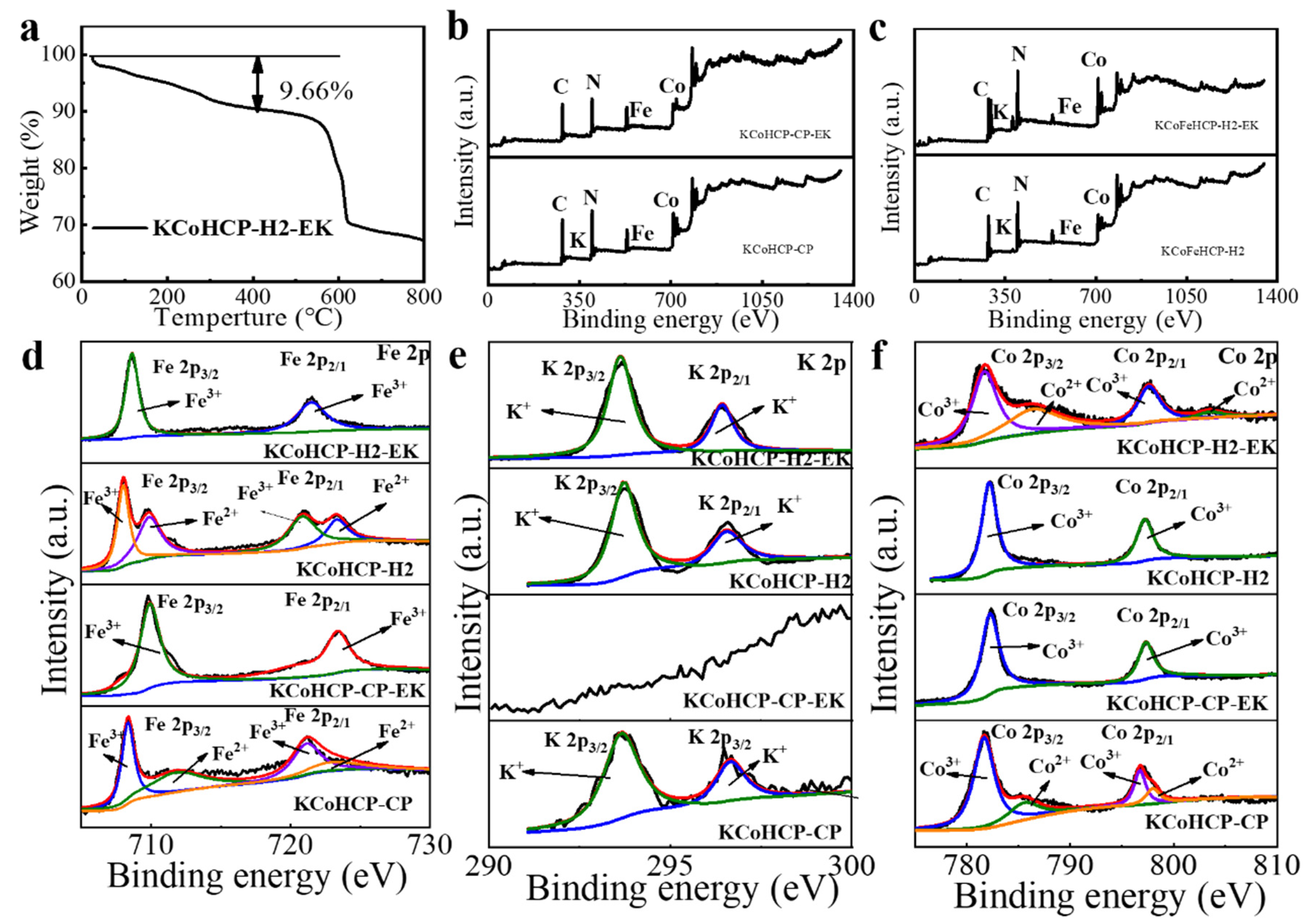
| Co | Fe | K | Other | |
|---|---|---|---|---|
| KCoHCP−CP | 12.7% | 12.9% | 11.4% | 63% |
| KCoHCP−CP−EK | 23.7% | 16.3% | 0.6% | 59.4% |
| KCoHCP−H2 | 11.6% | 12.0% | 14.5% | 50.3% |
| KCoHCP−H2−EK | 18.2% | 16.2% | 8.2% | 57.4% |
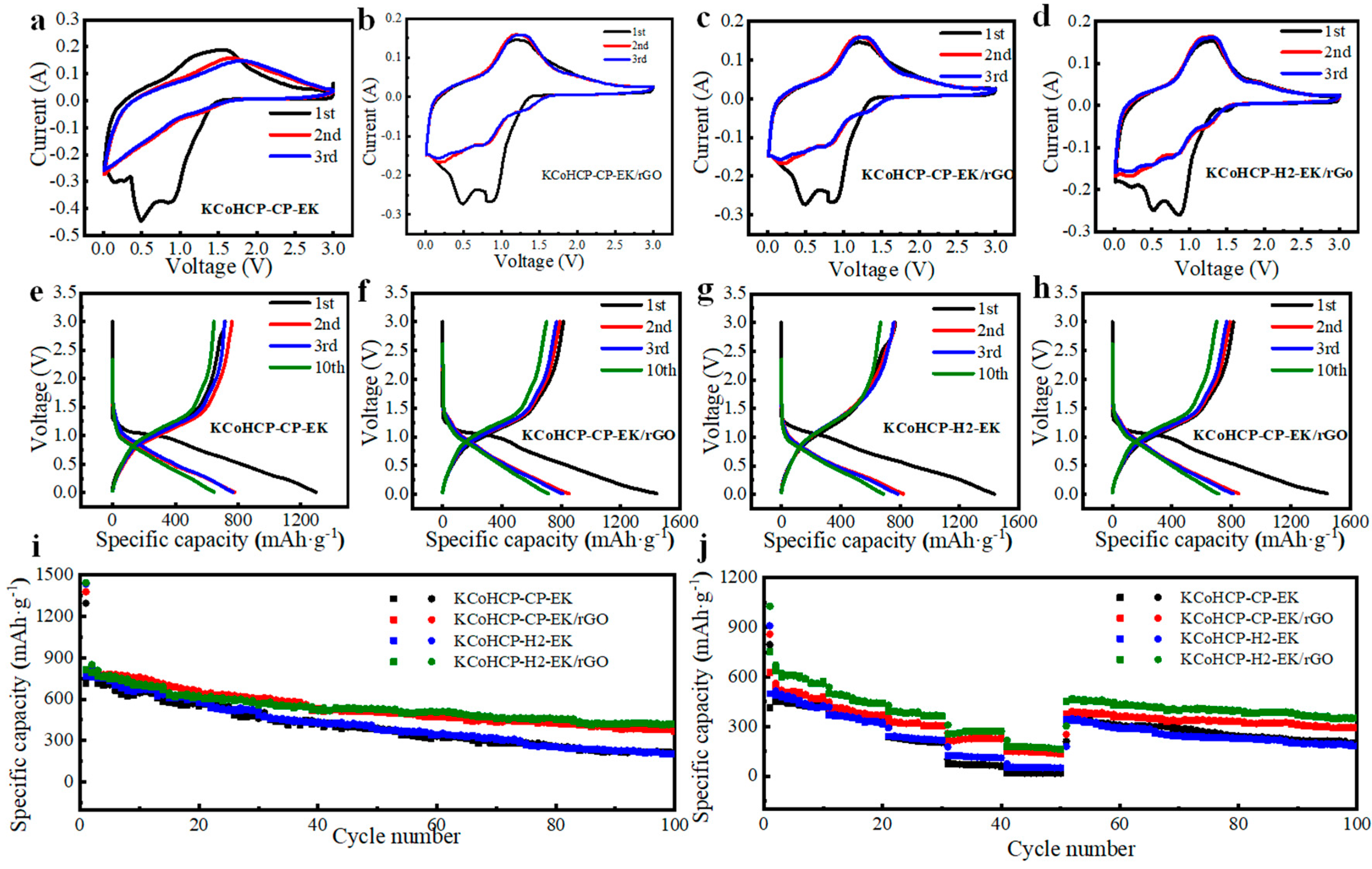
| Samples | Electrode Type | Cycling Properties | Ref. | |||
|---|---|---|---|---|---|---|
| Current Density (A·g−1) | Specific Capacity of Initial Discharge (mAh·g−1) | Cycle Number | Specific Capacity after Cycling (mAh·g−1) | |||
| K0.03Co1.45Fe(CN)6/5%rGo | SIBs anode | 0.1 | 1379.2 | 100 | 308.57 | This work |
| KCoFe(CN)6(H2)−EK/5%rGO | SIBs anode | 0.1 | 1444.5 | 100 | 420.54 | This work |
| FeHCF | SIBs anode | 0.6 | 80.0 | 250 | 68.8 | [22] |
| CrCr−PBA | SIBs anode | 0.5 | 108.2 | 100 | 101.1 | [23] |
| K1−xFe2+x/3(CN)6 | LIBs anode | 0.0875 | 450.0 | 40 | 375.5 | [24] |
| Co3[Co(CN)6]2 | LIBs anode | 0.02 | 566.2 | 5 | 304.0 | [25] |
| KMnHCF | LIBs anode | 0.05 | 777.0 | 50 | 485.0 | [37] |
| Hard carbon spheres | SIBs anode | 0.1 | 301 | 500 | 181 | [44] |
| Biomass derived hard carbon | SIBs anode | 0.02 | 413 | 500 | 320 | [45] |
| Orange peel derived hard carbon | SIBs anode | 0.07 | 170 | 100 | 125 | [46] |
| TiO2/MWCNTs | SIBs anode | 0.1 | 477 | 140 | 216 | [47] |
| Double−carbon enhanced TiO2 nanotubes | SIBs anode | 1 | 164 | 500 | 135.8 | [48] |
| TiO2/C | SIBs anode | 1 | 180 | 1600 | 175 | [49] |
| 3D Sb–Bi alloy/N−doped porous carbons (N–PCs) | SIBs anode | 10 | 318.3 | 6000 | 215.2 | [52] |
| Bi0.75Sb0.25 alloy | SIBs anode | 2.5 | 335 | 2000 | 291 | [53] |
Disclaimer/Publisher’s Note: The statements, opinions and data contained in all publications are solely those of the individual author(s) and contributor(s) and not of MDPI and/or the editor(s). MDPI and/or the editor(s) disclaim responsibility for any injury to people or property resulting from any ideas, methods, instructions or products referred to in the content. |
© 2023 by the authors. Licensee MDPI, Basel, Switzerland. This article is an open access article distributed under the terms and conditions of the Creative Commons Attribution (CC BY) license (https://creativecommons.org/licenses/by/4.0/).
Share and Cite
Zhou, G.; Fan, M.; Wang, L.; Li, X.; Liu, D.; Gao, F. KxCo1.5−0.5xFe(CN)6/rGO with Dual−Active Sodium Ion Storage Site as Superior Anode for Sodium Ion Battery. Nanomaterials 2023, 13, 264. https://doi.org/10.3390/nano13020264
Zhou G, Fan M, Wang L, Li X, Liu D, Gao F. KxCo1.5−0.5xFe(CN)6/rGO with Dual−Active Sodium Ion Storage Site as Superior Anode for Sodium Ion Battery. Nanomaterials. 2023; 13(2):264. https://doi.org/10.3390/nano13020264
Chicago/Turabian StyleZhou, Gang, Mincong Fan, Lei Wang, Xianglin Li, Danqing Liu, and Feng Gao. 2023. "KxCo1.5−0.5xFe(CN)6/rGO with Dual−Active Sodium Ion Storage Site as Superior Anode for Sodium Ion Battery" Nanomaterials 13, no. 2: 264. https://doi.org/10.3390/nano13020264
APA StyleZhou, G., Fan, M., Wang, L., Li, X., Liu, D., & Gao, F. (2023). KxCo1.5−0.5xFe(CN)6/rGO with Dual−Active Sodium Ion Storage Site as Superior Anode for Sodium Ion Battery. Nanomaterials, 13(2), 264. https://doi.org/10.3390/nano13020264