
Droplet-Based Microfluidic Preparation of Shape-Variable Alginate Hydrogel Magnetic Micromotors


Abstract
:1. Introduction
2. Materials and Methods
2.1. Chemical Materials
2.2. Synthesis of Fe3O4@Trisodium Citrate Nanoparticles
2.3. Preparation of Na-Alg/Fe3O4 Microparticles via Droplet-Based Microfluidics and Water Diffusion
2.4. Preparation of Ca-Alg/Fe3O4 Micromotors via Ionic Crosslinking
2.5. Characterization of Na-Alg/Fe3O4 Microparticles and Ca-Alg/Fe3O4 Micromotors
2.5.1. Scanning Electron Microscope
2.5.2. Confocal Laser Scanning Microscope
2.5.3. Locomotion of Ca-Alg/Fe3O4 Micromotors in External Magnetic Fields
3. Results and Discussion
3.1. Na-Alg/Fe3O4 Microparticles
3.1.1. Diameter and Volume
3.1.2. Interior Liquid
3.1.3. Stability
3.1.4. Morphology
3.1.5. Mechanism of the Formation of Na-Alg/Fe3O4 Microparticles
3.2. Ca-Alg/Fe3O4 Micromotors
3.2.1. Influence of on the Shape of Ca-Alg/Fe3O4 Micromotors
- (1)
- For Na-Alg/Fe3O4 microparticles prepared with at 0.09 mg/mL
- (2)
- For Na-Alg/Fe3O4 microparticles prepared with at 0.9 and 9 mg/mL
3.2.2. Mechanism of the Deformation
3.2.3. Characterization of Fe3O4 Nanoparticles inside Ca-Alg/Fe3O4 Micromotors
3.2.4. Locomotion of Ca-Alg/Fe3O4 Micromotors
4. Conclusions and Perspective
Supplementary Materials
Author Contributions
Funding
Institutional Review Board Statement
Informed Consent Statement
Data Availability Statement
Conflicts of Interest
References
- Joseph, A.; Contini, C.; Cecchin, D.; Nyberg, S.; Ruiz-Perez, L.; Gaitzsch, J.; Fullstone, G.; Tian, X.; Azizi, J.; Preston, J.; et al. Chemotactic Synthetic Vesicles: Design and Applications in Blood-Brain Barrier Crossing. Sci. Adv. 2017, 3, e1700362. [Google Scholar] [CrossRef]
- Luo, M.; Li, S.; Wan, J.; Yang, C.; Chen, B.; Guan, J. Enhanced Propulsion of Urease-Powered Micromotors by Multilayered Assembly of Ureases on Janus Magnetic Microparticles. Langmuir 2020, 36, 7005–7013. [Google Scholar] [CrossRef]
- Shao, J.; Xuan, M.; Zhang, H.; Lin, X.; Wu, Z.; He, Q. Chemotaxis-Guided Hybrid Neutrophil Micromotor for Actively Targeted Drug Transport. Angew. Chem. 2017, 129, 13115–13119. [Google Scholar] [CrossRef]
- Lin, X.; Xu, B.; Zhu, H.; Liu, J.; Solovev, A.; Mei, Y. Requirement and Development of Hydrogel Micromotors towards Biomedical Applications. Research 2020, 2020, 7659749. [Google Scholar] [CrossRef]
- Wang, B.; Kostarelos, K.; Nelson, B.J.; Zhang, L. Trends in Micro-/Nanorobotics: Materials Development, Actuation, Localization, and System Integration for Biomedical Applications. Adv. Mater. 2020, 33, 2002047. [Google Scholar] [CrossRef] [PubMed]
- Zhou, H.; Mayorga-Martinez, C.C.; Pané, S.; Zhang, L.; Pumera, M. Magnetically Driven Micro and Nanorobots. Chem. Rev. 2021, 121, 4999–5041. [Google Scholar] [CrossRef]
- Fernández-Medina, M.; Ramos-Docampo, M.A.; Hovorka, O.; Salgueiriño, V.; Städler, B. Recent Advances in Nano- and Micromotors. Adv. Funct. Mater. 2020, 30, 1908283. [Google Scholar] [CrossRef]
- Alapan, Y.; Bozuyuk, U.; Erkoc, P.; Karacakol, A.C.; Sitti, M. Multifunctional Surface Microrollers for Targeted Cargo Delivery in Physiological Blood Flow. Sci. Robot. 2020, 5, 5726. [Google Scholar] [CrossRef]
- Li, J.; Ji, F.; Ng, D.H.L.; Liu, J.; Bing, X.; Wang, P. Bioinspired Pt-Free Molecularly Imprinted Hydrogel-Based Magnetic Janus Micromotors for Temperature-Responsive Recognition and Adsorption of Erythromycin in Water. Chem. Eng. J. 2019, 369, 611–620. [Google Scholar] [CrossRef]
- Hu, N.; Wang, L.; Zhai, W.; Sun, M.; Xie, H.; Wu, Z.; He, Q. Magnetically Actuated Rolling of Star-Shaped Hydrogel Microswimmer. Macromol. Chem. Phys. 2018, 219, 1700540. [Google Scholar] [CrossRef]
- Xu, H.; Medina-Sánchez, M.; Schmidt, O.G. Magnetic Micromotors for Multiple Motile Sperm Cells Capture, Transport, and Enzymatic Release. Angew. Chem. 2020, 59, 15029–15037. [Google Scholar] [CrossRef] [PubMed]
- Wang, X.; Qin, X.-H.; Hu, C.; Terzopoulou, A.; Chen, X.-Z.; Huang, T.-Y.; Maniura-Weber, K.; Pané, S.; Nelson, B.J. 3D Printed Enzymatically Biodegradable Soft Helical Microswimmers. Adv. Funct. Mater. 2018, 28, 1804107. [Google Scholar] [CrossRef]
- Srivastava, S.K.; Ajalloueian, F.; Boisen, A. Thread-Like Radical-Polymerization via Autonomously Propelled (TRAP) Bots. Adv. Mater. 2019, 31, 1901573. [Google Scholar] [CrossRef]
- Seo, K.D.; Kwak, B.K.; Sánchez, S.; Kim, D.S. Microfluidic-Assisted Fabrication of Flexible and Location Traceable Organo-Motor. IEEE Trans. NanoBiosci. 2015, 14, 298–304. [Google Scholar] [CrossRef]
- Lu, A.X.; Liu, Y.; Oh, H.; Gargava, A.; Kendall, E.; Nie, Z.; DeVoe, D.L.; Raghavan, S.R. Catalytic Propulsion and Magnetic Steering of Soft, Patchy Microcapsules: Ability to Pick-Up and Drop-Off Microscale Cargo. ACS Appl. Mater. Interfaces 2016, 8, 15676–15683. [Google Scholar] [CrossRef]
- Al Nuumani, R.; Smoukov, S.K.; Bolognesi, G.; Vladisavljević, G.T. Highly Porous Magnetic Janus Microparticles with Asymmetric Surface Topology. Langmuir 2020, 36, 12702–12711. [Google Scholar] [CrossRef] [PubMed]
- Zou, M.; Wang, J.; Yu, Y.; Sun, L.; Wang, H.; Xu, H.; Zhao, Y. Composite Multifunctional Micromotors from Droplet Microfluidics. ACS Appl. Mater. Interfaces 2018, 10, 34618–34624. [Google Scholar] [CrossRef] [PubMed]
- Liu, J.; Chen, H.; Shi, X.; Nawar, S.; Werner, J.G.; Huang, G.; Ye, M.; Weitz, D.A.; Solovev, A.A.; Mei, Y. Hydrogel Microcapsules with Photocatalytic Nanoparticles for Removal of Organic Pollutants. Environ. Sci. Nano 2020, 7, 656–664. [Google Scholar] [CrossRef]
- Lin, X.; Zhu, H.; Zhao, Z.; You, C.; Kong, Y.; Zhao, Y.; Liu, J.; Chen, H.; Shi, X.; Makarov, D.; et al. Hydrogel-Based Janus Micromotors Capped with Functional Nanoparticles for Environmental Applications. Adv. Mater. Technol. 2020, 5, 2000279. [Google Scholar] [CrossRef]
- Yu, Y.; Shang, L.; Gao, W.; Zhao, Z.; Wang, H.; Zhao, Y. Microfluidic Lithography of Bioinspired Helical Micromotors. Angew. Chem. 2017, 129, 12295–12299. [Google Scholar] [CrossRef]
- Miao, T.; Wang, J.; Zeng, Y.; Liu, G.; Chen, X. Polysaccharide-Based Controlled Release Systems for Therapeutics Delivery and Tissue Engineering: From Bench to Bedside. Adv. Sci. 2018, 5, 1700513. [Google Scholar] [CrossRef]
- Agüero, L.; Zaldivar-Silva, D.; Peña, L.; Dias, M.L. Alginate Microparticles as Oral Colon Drug Delivery Device: A Review. Carbohydr. Polym. 2017, 168, 32–43. [Google Scholar] [CrossRef] [PubMed]
- Zhang, C.; Grossier, R.; Lacaria, L.; Rico, F.; Candoni, N.; Veesler, S. A Microfluidic Method Generating Monodispersed Microparticles with Controllable Sizes and Mechanical Properties. Chem. Eng. Sci. 2020, 211, 115322. [Google Scholar] [CrossRef]
- Stephenson, R.; Stuart, J. Mutual Binary Solubilities: Water-Alcohols and Water-Esters. J. Chem. Eng. Data 1986, 31, 56–70. [Google Scholar] [CrossRef]
- Wang, Y.; Liu, Y.; Li, Y.; Xu, D.; Pan, X.; Chen, Y.; Zhou, D.; Wang, B.; Feng, H.; Ma, X. Magnetic Nanomotor-Based Maneuverable SERS Probe. Research 2020, 2020, 1–13. [Google Scholar] [CrossRef]
- Rondeau, E.; Cooper-White, J.J. Biopolymer Microparticle and Nanoparticle Formation within a Microfluidic Device. Langmuir 2008, 24, 6937–6945. [Google Scholar] [CrossRef] [PubMed]
- Yang, J.; Katagiri, D.; Mao, S.; Zeng, H.; Nakajima, H.; Uchiyama, K. Generation of Controlled Monodisperse Porous Polymer Particles by Dipped Inkjet Injection. RSC Adv. 2015, 5, 7297–7303. [Google Scholar] [CrossRef]


| 0.09 | 31.9 ± 1.4 |
| 0.9 | 48.2 ± 1.6 |
| 9 | 102.7 ± 1.7 |
| Optical Schematic | Optical Schematic | Optical Schematic | |
|---|---|---|---|
| 10 wt% | 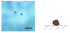 |  | 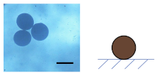 |
| 1 wt% | 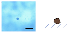 | 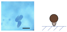 | 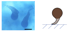 |
| 0.1 wt% | 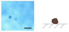 |  | 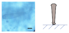 |
| 0.01 wt% | 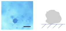 |  |  |
Publisher’s Note: MDPI stays neutral with regard to jurisdictional claims in published maps and institutional affiliations. |
© 2021 by the authors. Licensee MDPI, Basel, Switzerland. This article is an open access article distributed under the terms and conditions of the Creative Commons Attribution (CC BY) license (https://creativecommons.org/licenses/by/4.0/).
Share and Cite
Zhang, C.; Wang, Y.; Chen, Y.; Ma, X.; Chen, W. Droplet-Based Microfluidic Preparation of Shape-Variable Alginate Hydrogel Magnetic Micromotors. Nanomaterials 2022, 12, 115. https://doi.org/10.3390/nano12010115
Zhang C, Wang Y, Chen Y, Ma X, Chen W. Droplet-Based Microfluidic Preparation of Shape-Variable Alginate Hydrogel Magnetic Micromotors. Nanomaterials. 2022; 12(1):115. https://doi.org/10.3390/nano12010115
Chicago/Turabian StyleZhang, Cheng, Yong Wang, Yuduo Chen, Xing Ma, and Wenjun Chen. 2022. "Droplet-Based Microfluidic Preparation of Shape-Variable Alginate Hydrogel Magnetic Micromotors" Nanomaterials 12, no. 1: 115. https://doi.org/10.3390/nano12010115
APA StyleZhang, C., Wang, Y., Chen, Y., Ma, X., & Chen, W. (2022). Droplet-Based Microfluidic Preparation of Shape-Variable Alginate Hydrogel Magnetic Micromotors. Nanomaterials, 12(1), 115. https://doi.org/10.3390/nano12010115