Comparison of Nanomaterials with Other Unconventional Materials Used as Additives for Soil Improvement in the Context of Sustainable Development: A Review

Abstract
1. Introduction
2. Unconventional Materials Used in Soil Improvement
2.1. Nanomaterials
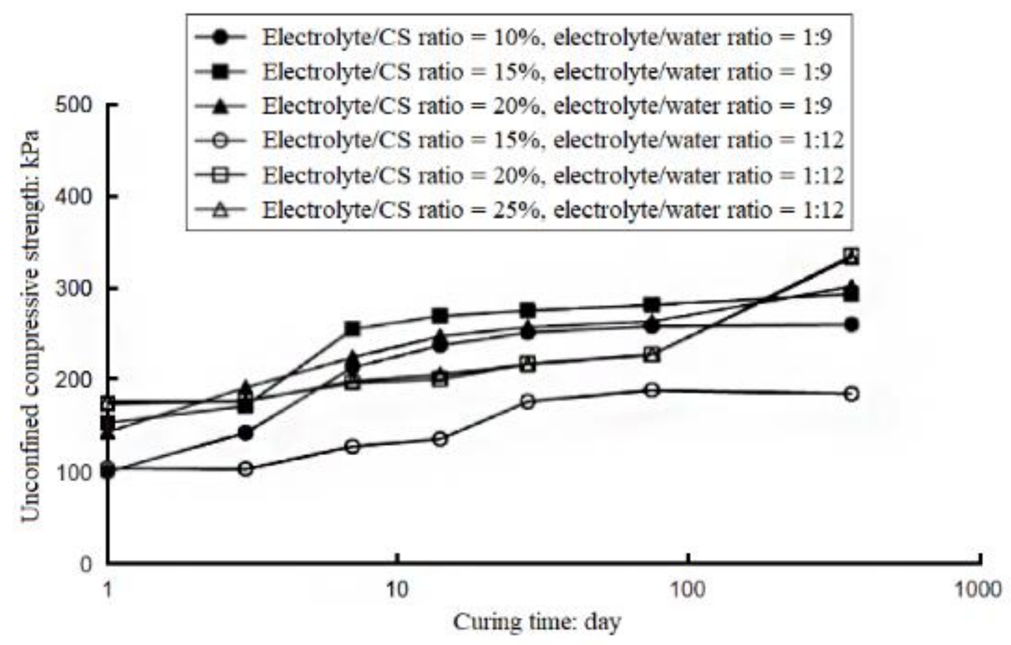
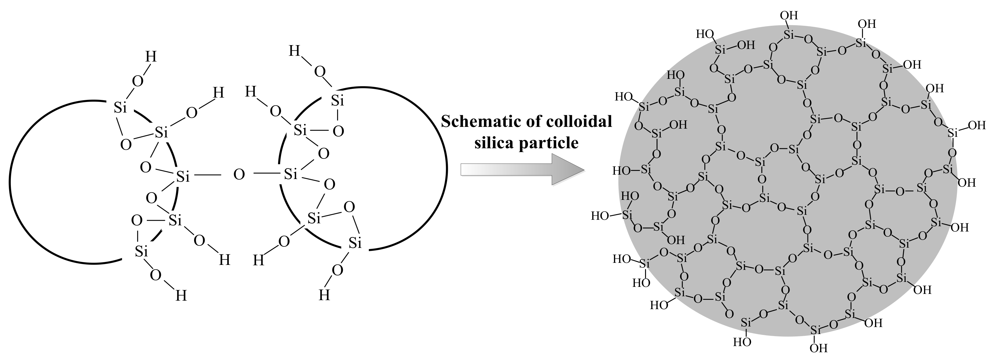
2.1.1. Colloidal Silica
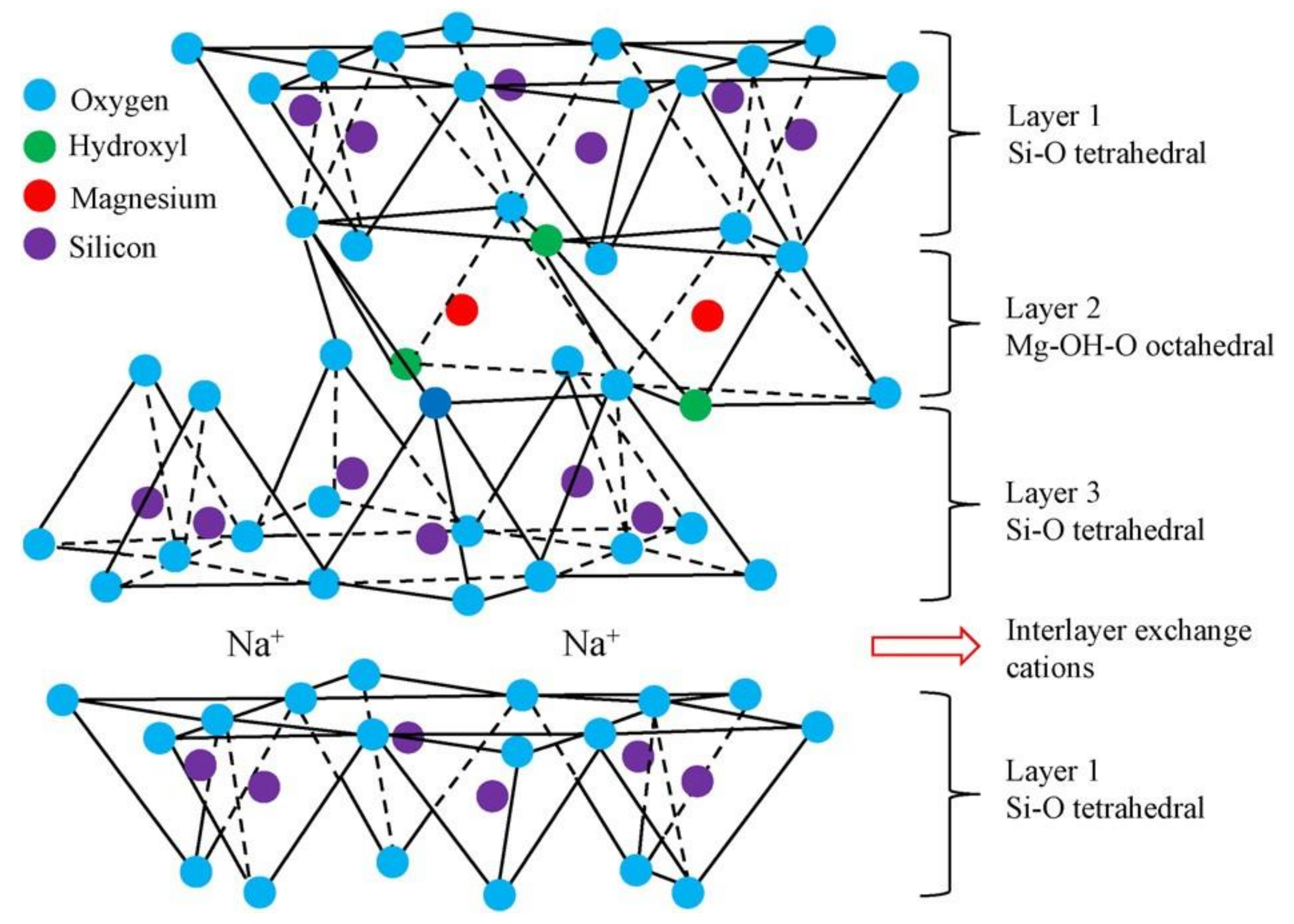
2.1.2. Bentonite
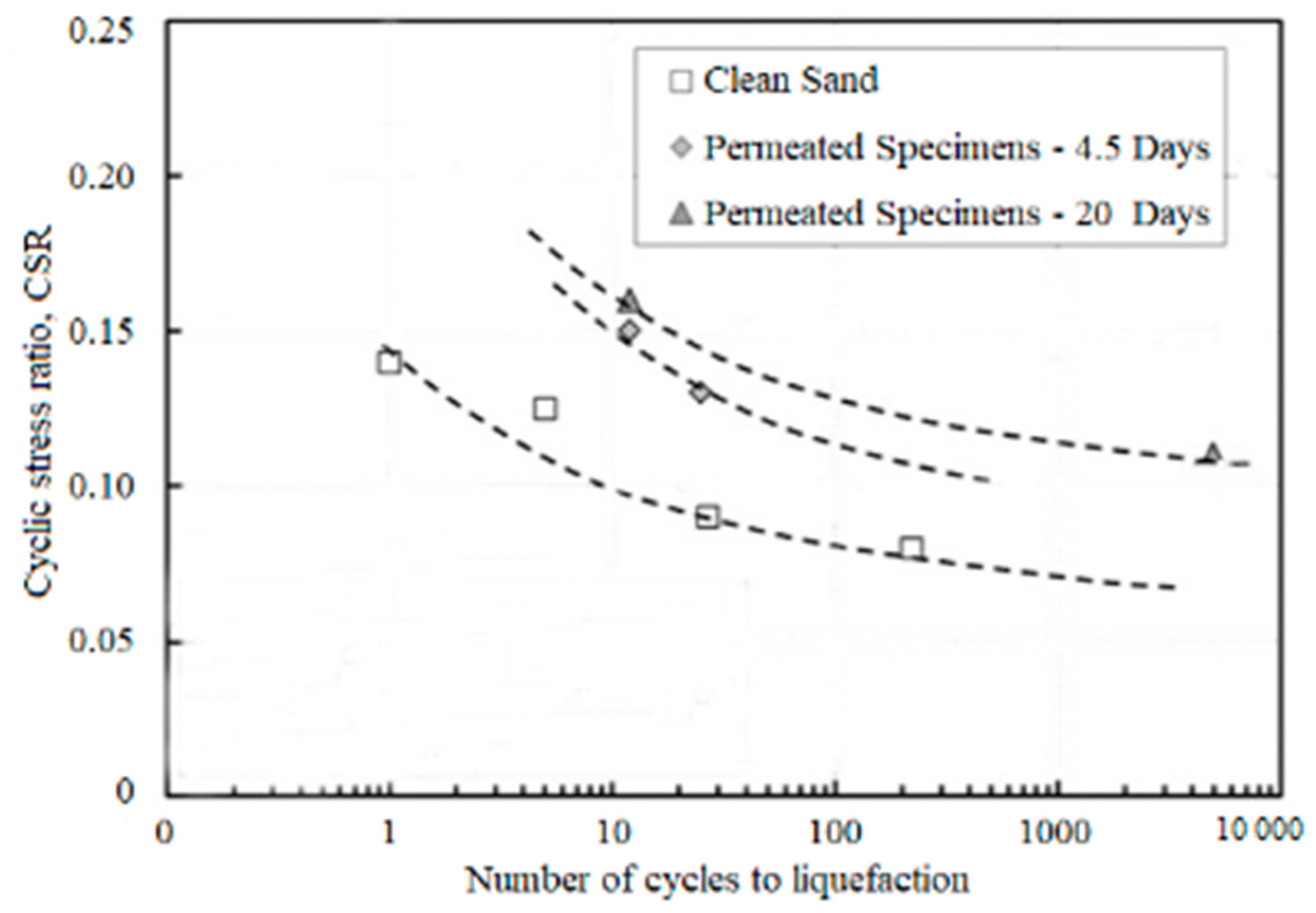
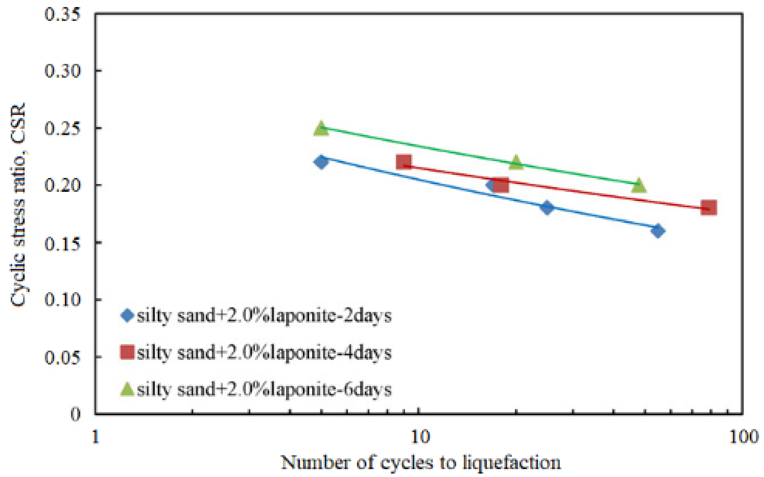
2.1.3. Laponite
2.1.4. Carbon Nanotube
2.2. Other Unconventional Materials
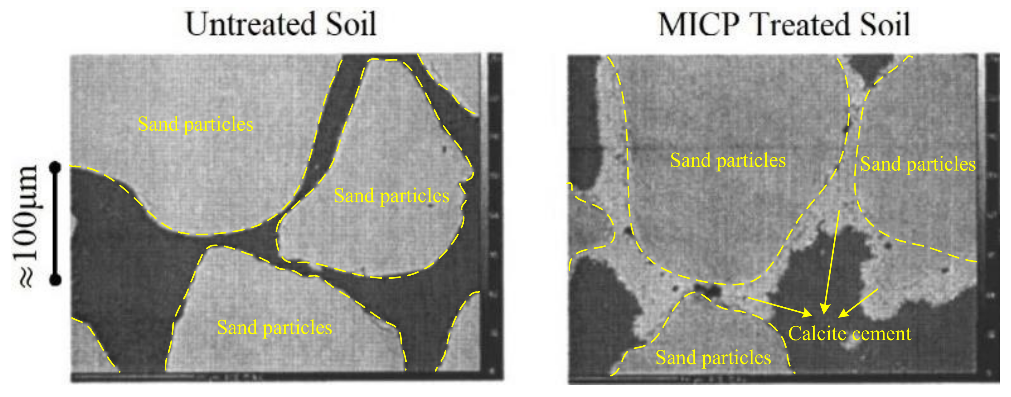
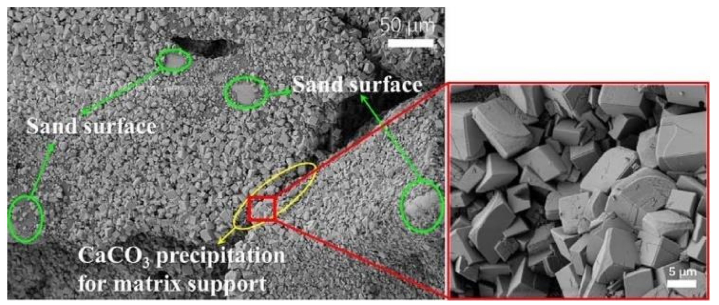
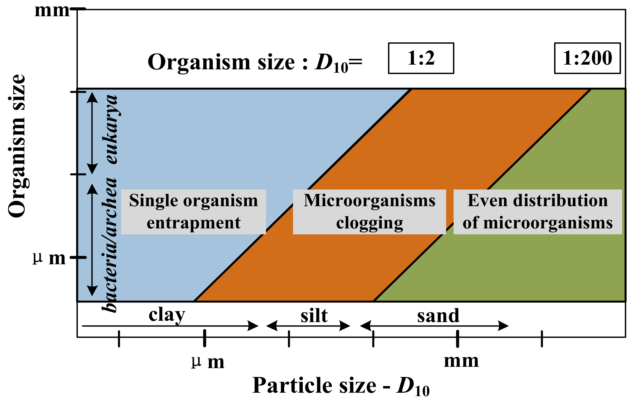
2.2.1. Microbially Induced Calcite Precipitation
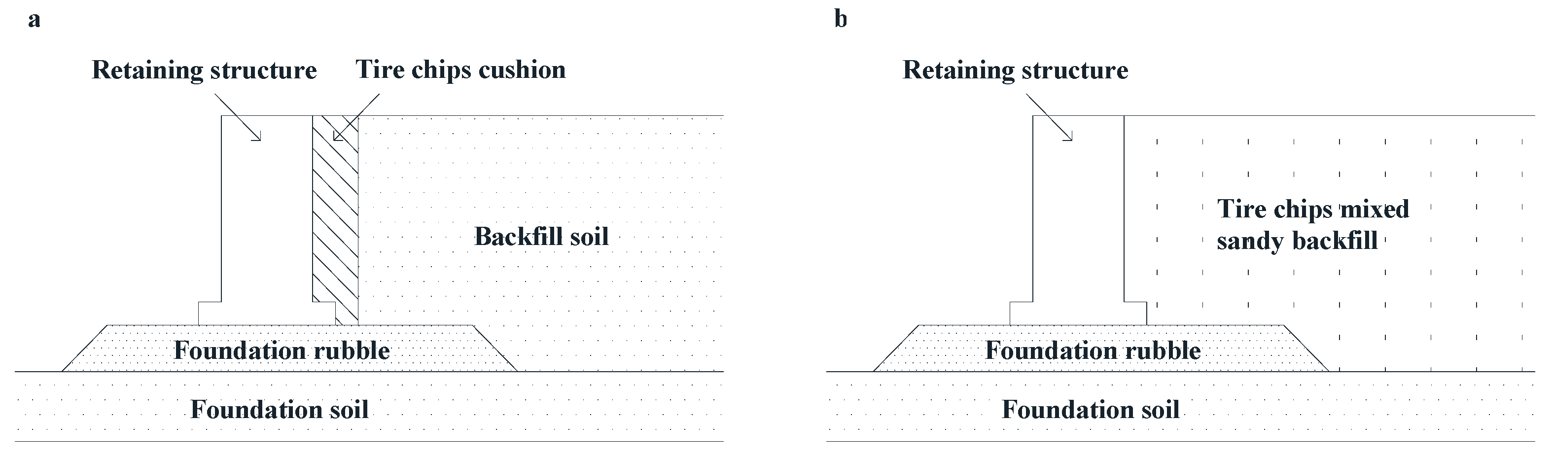
2.2.2. Recycled Tire
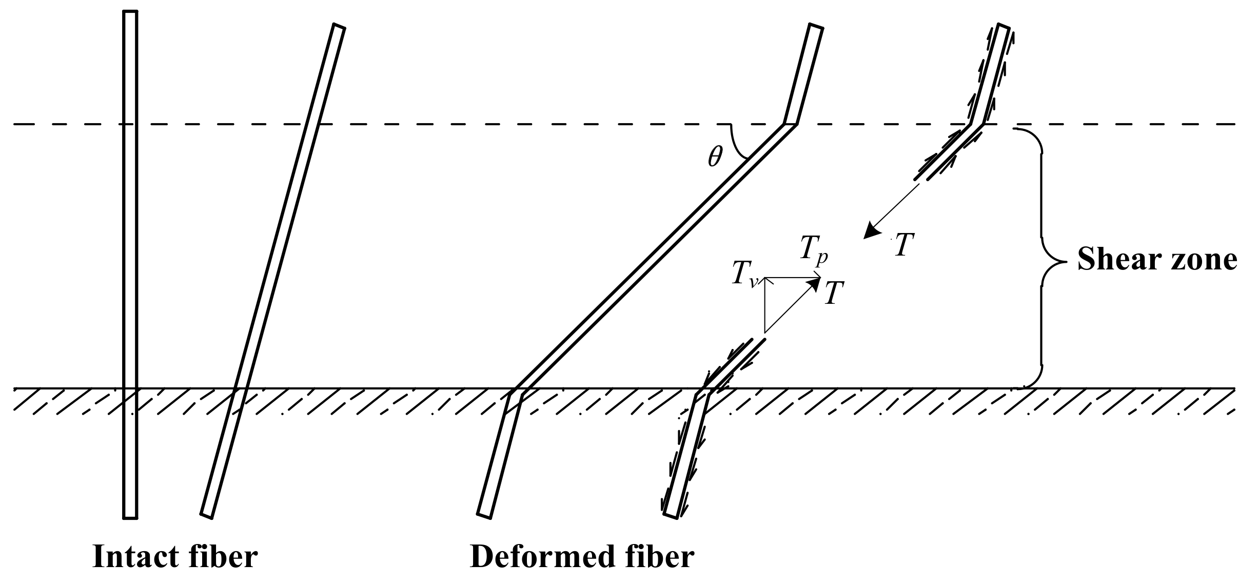
2.2.3. Environmental Fibers
3. Evaluation of Different Unconventional Materials
3.1. Reinforcement Mechanism
3.2. Reinforcement Effects and Characteristics
4. Price/Performance Ratio
5. Conclusions
- (1)
- Three kinds of cementing nanomaterials (i.e., colloidal silica, bentonite and laponite) have a more satisfactory reinforcement effect and higher price/performance ratio compared with traditional grouting materials and other unconventional materials. Therefore, nanomaterials have a broad prospect of development and application. Actually, colloidal silica has already been adopted for ground improvement under the runway and around common ducts of Fukuoka International Airport.
- (2)
- Colloidal silica is the most widely used nanomaterial for soil improvement up to now due to its comprehensive improvement, satisfactory effect and low price/performance ratio. However, laponite has attracted more attention of researchers in recent years since it has better performance in mitigating liquefaction. It has been shown that soils treated with 3% laponite have a similar liquefaction resistance to soils treated with 10% colloidal silica.
- (3)
- Microbially induced calcite precipitation (MICP) is an environmental-friendly material with remoldability and spontaneity. The calcite precipitation induced by microorganisms has a comprehensive effect on improving shear strength, adjusting permeability, mitigating liquefaction, purifying the environment, restoring metal contamination and so on. However, the selection of bacteria should be frequently adjusted within the engineering environment. The by-products, such as ammonium ion, nitrite, nitrous oxide, etc., should be cleaned in case of pollution. Nevertheless, MICP treatment will have the lowest cost if the relevant techniques mature in the future.
- (4)
- Granular materials have properties and reinforcement mechanisms that are quite different from cementing materials. They do not initially have low viscosity and ideal fluidity similar to pure water, so granular materials cannot be adopted for ground improvement in developed areas. On the other hand, granular materials have an excellent performance in reinforcing reconstituted soil, and tire chips and shreds may act as a cushion to protect soil structures.
- (5)
- Despite the satisfactory effect and high price/performance ratio of nanomaterials for soil improvement, there is also a growing concern that nanomaterials may have some unwanted or negative interactions with different organisms and the environment. Therefore, it is urgent that more environmental implication studies be carried out to verify the feasibility of nanomaterials adopted as additives for soil improvement.
Author Contributions
Funding
Conflicts of Interest
Ethical Approval
References
- Hejazi, S.M.; Sheikhzadeh, M.; Abtahi, S.M.; Zadhoush, A. A simple review of soil reinforcement by using natural and synthetic fibers. Constr. Build. Mater. 2012, 30, 100–116. [Google Scholar] [CrossRef]
- Consoli, N.C.; Prietto, P.D.M.; Ulbrich, L.A. Influence of Fiber and Cement Addition on Behavior of Sandy Soil. J. Geotech. Geoenviron. Eng. 1998, 124, 1211–1214. [Google Scholar] [CrossRef]
- Schaefer, V.R.; Filz, G.M.; Vanzler, L.S. SHRP2 R02 Phase 1—Geotechnical Solutions for Soil Improvement, Rapid Embankment Construction, and Stabilization of the Pavement Working Platform. Adv. Ground Improv. 2009, 1–11. [Google Scholar] [CrossRef][Green Version]
- Terti, G.; Savoia, M.; Azevedo, J.; Bloodworth, A.; De Roeck, G.; Esteban-Chapapria, V.; Lobo, A.; Lombaert, G.; Magenes, G.; Prinos, P.; et al. SASICE: Safety and sustainability in civil engineering. In Proceedings of the 1st EUCEET Association Conference, Patras, Greece, 24–25 November 2011; pp. 88–97. [Google Scholar]
- Li, X.; Guo, L. Study on Civil Engineering Sustainable Development Strategy. In Proceedings of the International Conference on Management, Education, Information and Control, Shenyang, China, 29–31 May 2015. [Google Scholar]
- Kumar, V.R.; Bhuvaneshwari, B.; Maheswaran, S.; Palani, G.S.; Ravisankar, K.; Iyer, N.R. An overview of techniques based on biomimetics for sustainable development of concrete. Curr. Ence 2011, 101, 741–747. [Google Scholar]
- Basu, D.; Misra, A.; Puppala, A.J. Sustainability and geotechnical engineering: Perspectives and review. Can. Geotech. J. 2015, 52, 96–113. [Google Scholar] [CrossRef]
- Mouton, Y. Organic Materials for Sustainable Civil Engineering; Wiley & Sons: Hoboken, NJ, USA, 2011. [Google Scholar]
- Huang, Y.; Wang, L. Experimental studies on nanomaterials for soil improvement: A review. Environ. Earth Sci. 2016, 75, 1–10. [Google Scholar] [CrossRef]
- Bao, X.; Jin, Z.; Cui, H.; Chen, X.; Xie, X. Soil liquefaction mitigation in geotechnical engineering: An overview of recently developed methods. Soil Dyn. Earthq. Eng. 2019, 120, 273–291. [Google Scholar] [CrossRef]
- Wong, C.; Pedrotti, M.; El Mountassir, G.; Lunn, R.J. A study on the mechanical interaction between soil and colloidal silica gel for ground improvement. Eng. Geol. 2018, 243, 84–100. [Google Scholar] [CrossRef]
- Changizi, F.; Haddad, A. Improving the geotechnical properties of soft clay with nano-silica particles. Proc. Inst. Civ. Eng. Ground Improv. 2017, 170, 62–71. [Google Scholar] [CrossRef]
- Persoff, P.; Apps, J.; Moridis, G.; Whang, J.M. Effect of Dilution and Contaminants on Sand Grouted with Colloidal Silica. J. Geotech. Geoenviron. Eng. 1999, 125, 461–469. [Google Scholar] [CrossRef]
- Mollamahmutoglu, M.; Yilmaz, Y. Pre-and post-cyclic loading strength of silica-grouted sand. Proc. Inst. Civ. Eng. Geotech. Eng. 2010, 163, 343–348. [Google Scholar] [CrossRef]
- Gallagher, P.M.; Mitchell, J.K. Influence of colloidal silica grout on liquefaction potential and cyclic undrained behavior of loose sand. Soil Dyn. Earthq. Eng. 2002, 22, 1017–1026. [Google Scholar] [CrossRef]
- Kodaka, T.; Ohno, Y.; Takyu, T. Cyclic Shear Characteristics of Treated Sand with Colloidal Silica Grout. In Proceedings of the 16th International Conference on Soil Mechanics and Geotechnical Engineering: Geotechnology in Harmony with the Global Environment, Osaka, Japan, 12–15 September 2005; Volume 2, pp. 401–404. [Google Scholar]
- Díaz-Rodríguez, J.A.; Antonio-Izarraras, V.M.; Bandini, P.; López-Molina, J.A. Cyclic strength of a natural liquefiable sand stabilized with colloidal silica grout. Can. Geotech. J. 2008, 45, 1345–1355. [Google Scholar] [CrossRef]
- Spencer, L.; Rix, G.J.; Gallagher, P. Colloidal Silica Gel and Sand Mixture Dynamic Properties. In Geotechnical Earthquake Engineering and Soil Dynamics IV; American Society of Civil Engineers (ASCE): Reston, VA, USA, 2008; pp. 1–10. [Google Scholar]
- Bergna, H.B.; Roberts, W.O. RobertsColloid Chemistry of Silica: An Overview. Colloidal Silica 2005, 37–64. [Google Scholar] [CrossRef]
- Conlee, C.T.; Gallagher, P.M.; Boulanger, R.W.; Kamai, R. Centrifuge Modeling for Liquefaction Mitigation Using Colloidal Silica Stabilizer. J. Geotech. Geoenviron. Eng. 2012, 138, 1334–1345. [Google Scholar] [CrossRef]
- Moridis, G.J.; Persoff, P.; Apps, J.A.; Myer, L.; Pruess, K.; Yen, P. A Field Test of Permeation Grouting in Heterogeneous Soils Using a New Generation of Barrier Liquids; Lawrence Berkeley National Laboratory: Berkeley, CA, USA, 1995.
- Teplitskiy, A.; Gee, R.; Kourmaev, R. Application of physical-chemical properties of bentonite utilized in construction, as viewed through the TRIZ prism. TRIZ J. 2005. Available online: http://www.triz-journal.com/archives/2005/10/05.pdf. (accessed on 30 April 2020).
- El Mohtar, C.S.; Clarke, J.; Bobet, A.; Santagata, M.; Drnevich, V.; Johnston, C. Cyclic Response of a Sand with Thixotropic Pore Fluid. In Proceedings of the Geotechnical Earthquake Engineering and Soil Dynamics IV, Sacramento, CA, USA, 18–22 May 2008. [Google Scholar] [CrossRef][Green Version]
- Rugg, D.A.; Yoon, J.; Hwang, H.; El Mohtar, C.S. Undrained Shearing Properties of Sand Permeated with a Bentonite Suspension for Static Liquefaction Mitigation. Geo-Frontiers 2011, 677–686. [Google Scholar] [CrossRef]
- El Mohtar, C.S.; Bobet, A.; Santagata, M.C.; Drnevich, V.P.; Johnston, C.T. Liquefaction Mitigation Using Bentonite Suspensions. J. Geotech. Geoenviron. Eng. 2013, 139, 1369–1380. [Google Scholar] [CrossRef]
- El Mohtar, C.; Bobet, A.; Drnevich, V.; Johnston, C.T.; Santagata, M. Pore pressure generation in sand with bentonite: From small strains to liquefaction. Géotechnique 2014, 64, 108–117. [Google Scholar] [CrossRef]
- Witthoeft, A.F.; Santagata, M.C.; Bobet, A. Numerical Study of the Effectiveness of Bentonite Treatment for Liquefaction Mitigation. In Proceedings of the GeoCongress 2012, Oakland, CA, USA, 25–29 March 2012; pp. 1958–1967. [Google Scholar] [CrossRef]
- Hwang, H.; Yoon, J.; Rugg, D.; El Mohtar, C.S. Hydraulic Conductivity of Bentonite Grouted Sand. Geo-Frontiers 2011, 1372–1381. [Google Scholar] [CrossRef]
- Mohtar, E.L.; ElKhattab, M.; Sangroya, R. Post-Grouting Stability of Bentonite Suspensions within Sand Pores. Geotechn. Spec. Pub. 2015, 2296–2305. [Google Scholar] [CrossRef]
- Ochoa-Cornejo, F.; Bobet, A.; Johnston, C.; Santagata, M.; Sinfield, J.V. Liquefaction 50 Years after Anchorage 1964; How Nanoparticles Could Prevent It. In Proceedings of the 10 th National Conference in Earthquake Engineering, Anchorage, AL, USA, 21–25 July 2014. [Google Scholar]
- Huang, Y.; Wang, L. Laboratory investigation of liquefaction mitigation in silty sand using nanoparticles. Eng. Geol. 2016, 204, 23–32. [Google Scholar] [CrossRef]
- Ochoa-Cornejo, F.; Bobet, A.; Johnston, C.; Santagata, M.; Sinfield, J.V. Dynamic properties of a sand–nanoclay composite. Géotechnique 2020, 70, 210–225. [Google Scholar] [CrossRef]
- Huang, Y.; Wen, Z.; Wang, L.; Zhu, C. Centrifuge testing of liquefaction mitigation effectiveness on sand foundations treated with nanoparticles. Eng. Geol. 2019, 249, 249–256. [Google Scholar] [CrossRef]
- Morsy, M.; Alsayed, S.; Aqel, M. Hybrid effect of carbon nanotube and nano-clay on physico-mechanical properties of cement mortar. Constr. Build. Mater. 2011, 25, 145–149. [Google Scholar] [CrossRef]
- Liu, Q.; Sun, W.; Jiang, H.; Wang, C. Effects of carbon nanotubes on mechanical and 2D-3D microstructure properties of cement mortar. J. Wuhan Univ. Technol. Sci. Ed. 2014, 29, 513–517. [Google Scholar] [CrossRef]
- Kim, H.K.; Nam, I.; Lee, H. Enhanced effect of carbon nanotube on mechanical and electrical properties of cement composites by incorporation of silica fume. Compos. Struct. 2014, 107, 60–69. [Google Scholar] [CrossRef]
- Arabania, M.; Haghib, A.K.; Moradic, Y. Evaluation of mechanical properties improvement of clayey sand by using carbon nanotubes. In Proceedings of the 4th International Conference on Nanostructures (ICNS4), Kish Island, Iran, 12–14 March 2012. [Google Scholar]
- Figueiredo, D.T.; Correia, A.A.S.; Hunkeler, D.; Rasteiro, M.G. Surfactants for dispersion of carbon nanotubes applied in soil stabilization. Colloids Surfaces A: Physicochem. Eng. Asp. 2015, 480, 405–412. [Google Scholar] [CrossRef]
- Li, S.; Anderson, T.A.; Green, M.J.; Maul, J.D.; Cañas-Carrell, J.E. Polyaromatic hydrocarbons (PAHs) sorption behavior unaffected by the presence of multi-walled carbon nanotubes (MWNTs) in a natural soil system. Environ. Sci. Process. Impacts 2013, 15, 1130–1136. [Google Scholar] [CrossRef]
- Jin, L.; Son, Y.; Yoon, T.K.; Kang, Y.J.; Kim, W.; Chung, H. High concentrations of single-walled carbon nanotubes lower soil enzyme activity and microbial biomass. Ecotoxicol. Environ. Saf. 2013, 88, 9–15. [Google Scholar] [CrossRef] [PubMed]
- Jin, L.; Son, Y.; Deforest, J.L.; Kang, Y.J.; Kim, W.; Chung, H. Single-walled carbon nanotubes alter soil microbial community composition. Sci. Total. Environ. 2014, 466, 533–538. [Google Scholar] [CrossRef] [PubMed]
- Tong, Z.; Bischoff, M.; Nies, L.; Applegate, B.; Turco, R.F. Impact of Fullerene (C60) on a Soil Microbial Community. Environ. Sci. Technol. 2007, 41, 2985–2991. [Google Scholar] [CrossRef] [PubMed]
- Umar, M.; Kassim, K.A.; Chiet, K.T.P. Biological process of soil improvement in civil engineering: A review. J. Rock Mech. Geotech. Eng. 2016, 8, 767–774. [Google Scholar] [CrossRef]
- DeJong, J.T.; Fritzges, M.B.; Nüsslein, K. Microbially Induced Cementation to Control Sand Response to Undrained Shear. J. Geotech. Geoenviron. Eng. 2006, 132, 1381–1392. [Google Scholar] [CrossRef]
- Cheng, X.; Ma, Q.; Yang, Z.; Zhang, Z.; Meng, L. Dynamic response of liquefiable sand foundation improved by bio-grouting. Chin. J. Geotech. Eng. 2013, 35, 1486–1495. (In Chinese) [Google Scholar]
- Ferris, F.; Stehmeier, L.; Kantzas, A.; Mourits, F. Bacteriogenic Mineral Plugging. J. Can. Pet. Technol. 1997, 36, 56–61. [Google Scholar] [CrossRef]
- Xiao, P.; Liu, H.; Xiao, Y.; Stuedlein, A.W.; Evans, T.M. Liquefaction resistance of bio-cemented calcareous sand. Soil Dyn. Earthq. Eng. 2018, 107, 9–19. [Google Scholar] [CrossRef]
- Filet, A.E.; Gadret, J.-P.; Loygue, M.; Borel, S. Biocalcis and its Applications for the Consolidation of Sands. In Proceedings of the Fourth International Conference on Grouting and Deep Mixing, New Orleans, LO, USA, 15–18 February 2012. [Google Scholar] [CrossRef]
- Chu, J.; Ivanov, V.; He, J.; Naeimi, M.; Li, B.; Stabnikov, V. Development of Microbial Geotechnology in Singapore. Geo Front. 2011, 4070–4078. [Google Scholar] [CrossRef]
- Chu, J.; Ivanov, V.; Naeimi, M.; Stabnikov, V.; Liu, H.-L. Optimization of calcium-based bioclogging and biocementation of sand. Acta Geotech. 2014, 9, 277–285. [Google Scholar] [CrossRef]
- Shanahan, C.; Montoya, B.M. Strengthening Coastal Sand Dunes Using Microbial-Induced Calcite Precipitation. In Proceedings of the Conference From Soil Behavior Fundamentals to Innovations in Geotechnical Engineering, Atlanta, GA, USA, 23–26 February 2014; pp. 1683–1692. [Google Scholar] [CrossRef]
- Jiang, N.; Soga, K.; Dawoud, O.; Abu-Farsakh, M.; Yu, X.; Hoyos, L.R. Experimental Study of the Mitigation of Soil Internal Erosion by Microbially Induced Calcite Precipitation. In Proceedings of the Conference From Soil Behavior Fundamentals to Innovations in Geotechnical Engineering, Atlanta, GA, USA, 23–26 February 2014; pp. 1586–1595. [Google Scholar] [CrossRef]
- Shanahan, C.; Montoya, B.M. Erosion Reduction of Coastal Sands Using Microbial Induced Calcite Precipitation. In Geo-Chicago 2016; American Society of Civil Engineers (ASCE): Reston, VA, USA, 2016; pp. 42–51. [Google Scholar]
- Jiang, N.; Soga, K. The applicability of microbially induced calcite precipitation (MICP) for internal erosion control in gravel–sand mixtures. Géotechnique 2017, 67, 42–55. [Google Scholar] [CrossRef]
- Montoya, B.; DeJong, J.T.; Boulanger, R.W.; Wilson, D.W.; Gerhard, R.; Ganchenko, A.; Chou, J.-C. Liquefaction Mitigation Using Microbial Induced Calcite Precipitation. In Proceedings of the GeoCongress 2012, Oakland, CA, USA, 25–29 March 2012; pp. 1918–1927. [Google Scholar] [CrossRef]
- Montoya, B.; DeJong, J.T.; Boulanger, R.W. Dynamic response of liquefiable sand improved by microbial-induced calcite precipitation. Géotechnique 2013, 63, 302–312. [Google Scholar] [CrossRef]
- Hazarika, H.; Yasuhara, K.; Kikuchi, Y.; Karmokar, A.K.; Mitarai, Y. Multifaceted potentials of tire-derived three dimensional geosynthetics in geotechnical applications and their evaluation. Geotext. Geomembr. 2010, 28, 303–315. [Google Scholar] [CrossRef]
- Mitarai, Y.; Yasuhara, K.; Kikuchi, Y.; Karmokar, A.K. Application of cement treated clay added with tire chips to the sealing materials of coastal waste disposal site. In Proceedings of the 5th ICEG Environmental Geotechnics: Opportunities, Challenges and Responsibilities for Environmental Geotechnics, Cardiff, UK, 26–30 June 2006; pp. 757–764. [Google Scholar]
- Pincus, H.; Edil, T.; Bosscher, P. Engineering Properties of Tire Chips and Soil Mixtures. Geotech. Test. J. 1994, 17, 453. [Google Scholar] [CrossRef]
- Huang, Y.; Wen, Z. Recent developments of soil improvement methods for seismic liquefaction mitigation. Nat. Hazards 2014, 76, 1927–1938. [Google Scholar] [CrossRef]
- Hyodo, M.; Yamada, S.; Orense, R.P.; Okamoto, M.; Hazarika, H. Undrained cyclic shear properties of tire chip-sand mixtures. In Proceedings of the International Workshop on Scrap Tire Derived Geomaterials—Opportunities and Challenges, Yokosuka, Japan, 23–24 March 2007; pp. 187–196. [Google Scholar]
- Bahadori, H.; Manafi, S. Effect of tyre chips on dynamic properties of saturated sands. Int. J. Phys. Model. Geotech. 2015, 15, 116–128. [Google Scholar] [CrossRef]
- Hazarika, H. Structural stability and flexibility during earthquakes using tyres (SAFETY)—A novel application for seismic disaster mitigation. In Proceedings of the International Workshop on Scrap Tire Derived Geomaterials—Opportunities and Challenges, Yokosuka, Japan, 23–24 March 2007; pp. 115–125. [Google Scholar]
- Hazarika, H.; Kohama, E.; Sugano, T. Underwater Shake Table Tests on Waterfront Structures Protected with Tire Chips Cushion. J. Geotech. Geoenviron. Eng. 2008, 134, 1706–1719. [Google Scholar] [CrossRef]
- Hazarika, H.; Hyodo, M.; Yasuhara, K. Investigation of Tire Chips-Sand Mixtures As Preventive Measure against Liquefaction. Soil Behav. Geo-Micromech. 2010, 338–345. [Google Scholar] [CrossRef]
- Towhata, I. Mitigation of Liquefaction-Induced Damage. In Critical Thinking in the Sustainable Rehabilitation and Risk Management of the Built Environment; Springer International Publishing: Berlin, Germany, 2008; pp. 588–642. [Google Scholar] [CrossRef]
- Pasha, S.M.K.; Hazarika, H.; Yoshimoto, N. Physical and mechanical properties of Gravel-Tire Chips Mixture (GTCM). Geosynth. Int. 2019, 26, 92–110. [Google Scholar] [CrossRef]
- Chenari, R.J.; Fard, M.K.; Shafie, J.; Ghorbanpour, A. Tire Shreds and Tire Crumbs Inclusion: Contrast Effects on Bearing Capacity of Sand. Electr. J. Geotech. Eng. 2017, 22, 3649–3667. [Google Scholar]
- Bahadori, H.; Farzalizadeh, R. Dynamic Properties of Saturated Sands Mixed with Tyre Powders and Tyre Shreds. Int. J. Civ. Eng. 2016, 16, 395–408. [Google Scholar] [CrossRef]
- Ghazavi, M. Shear strength characteristics of sand-mixed with granular rubber. Geotech. Geol. Eng. 2004, 22, 401–416. [Google Scholar] [CrossRef]
- Meddah, A.; Merzoug, K. Feasibility of using rubber waste fibers as reinforcements for sandy soils. Innov. Infrastruct. Solut. 2017, 2, 5. [Google Scholar] [CrossRef]
- Olufowobi, J.; Ogundoju, A.; Michael, B.; Aderinlewo, O. Clay Soil Stabilisation Using Powdered Glass. J. Eng. Sci. Technol. 2014, 9, 541–558. [Google Scholar]
- Ghiassian, H.; Jamshidi, R.; Tabarsa, A.R. Dynamic Performance of Toyoura Sand Reinforced with Randomly Distributed Carpet Waste Strips. In Proceedings of the Geotechnical Earthquake Engineering and Soil Dynamics IV, Sacramento, CA, USA, 18–22 May 2008. [Google Scholar] [CrossRef]
- Ghiassian, H.; Shahnazari, H.; Noorzad, A.; Tabarsa, A.R.; Chenari, R.J. Nonlinear behavior of fine sand reinforced with carpet waste strips in undrained cyclic loading. Kuwait J. Ence Eng. 2012, 39, 15–36. [Google Scholar]
- Gray, D.H.; Ohashi, H. Mechanics of Fiber Reinforcement in Sand. J. Geotech. Eng. 1983, 109, 335–353. [Google Scholar] [CrossRef]
- Ye, B.; Cheng, Z.R.; Liu, C.; Zhang, Y.D.; Lu, P. Liquefaction resistance of sand reinforced with randomly distributed polypropylene fibres. Geosynth. Int. 2017, 24, 625–636. [Google Scholar] [CrossRef]
- Chauhan, M.S.; Mittal, S.; Mohanty, B. Performance evaluation of silty sand subgrade reinforced with fly ash and fibre. Geotext. Geomembr. 2008, 26, 429–435. [Google Scholar] [CrossRef]
- Ahmad, F.; Bateni, F.; Azmi, M. Performance evaluation of silty sand reinforced with fibres. Geotext. Geomembr. 2010, 28, 93–99. [Google Scholar] [CrossRef]
- Bouhicha, M.; Aouissi, F.; Kenai, S. Performance of composite soil reinforced with barley straw. Cem. Concr. Compos. 2005, 27, 617–621. [Google Scholar] [CrossRef]
- Kirar, B.; Maheshwari, B.K.; Jakka, R.S. Dynamic Properties of Solani Sand Reinforced with Coir Fibers. In Proceedings of the 15th World Conference on Earthquake Engineering, Lisbon, Portugal, 24–28 September 2012. [Google Scholar]
- Sahu, R.; Ayothiraman, R.; Ramana, G. Effect of Waste Human Hair Fibers on Shear Behavior of Sand in Dry and Saturated Conditions. J. Test. Eval. 2018, 47, 153–173. [Google Scholar] [CrossRef]
- Sahu, R.; Ramaiah, B.J.; Ayothiraman, R.; Ramana, G.V. Dynamic Properties of Human Hair Fiber–Reinforced Yamuna Sand. J. Test. Eval. 2019, 48, 48. [Google Scholar] [CrossRef]
- Ateş, A. Mechanical properties of sandy soils reinforced with cement and randomly distributed glass fibers (GRC). Compos. Part B Eng. 2016, 96, 295–304. [Google Scholar] [CrossRef]
- Gray, D.H.; Alrefeai, T. Behavior of Fabric-Versus Fiber-Reinforced Sand. J. Geotech. Eng. 1986, 112, 804–820. [Google Scholar] [CrossRef]
- Maher, M.H.; Woods, R.D. Dynamic Response of Sand Reinforced with Randomly Distributed Fibers. J. Geotech. Eng. 1990, 116, 1116–1131. [Google Scholar] [CrossRef]
- Orakoglu, M.E.; Liu, J. Effect of freeze-thaw cycles on triaxial strength properties of fiber-reinforced clayey soil. KSCE J. Civ. Eng. 2017, 21, 2128–2140. [Google Scholar] [CrossRef]
- Orakoglu, M.E.; Liu, J.; Niu, F. Dynamic behavior of fiber-reinforced soil under freeze-thaw cycles. Soil Dyn. Earthq. Eng. 2017, 101, 269–284. [Google Scholar] [CrossRef]
- Consoli, N.C.; Montardo, J.P.; Donato, M.; Prietto, P.D.M. Effect of material properties on the behaviour of sand—cement—fibre composites. Ground Improv. 2004, 8, 77–90. [Google Scholar] [CrossRef]
- Bouaricha, L.; Henni, A.D. Combined Effect of Layers Number and the Glass Fiber Type on the Shear Strength Characteristics of Chlef sandy soil. Iran. J. Sci. Technol. Trans. Civ. Eng. 2020, 44, 107–114. [Google Scholar] [CrossRef]
- Gallagher, P.M.; Pamuk, A.; Abdoun, T. Stabilization of Liquefiable Soils Using Colloidal Silica Grout. J. Mater. Civ. Eng. 2007, 19, 33–40. [Google Scholar] [CrossRef]
- Gallagher, P.M.; Lin, Y. Colloidal Silica Transport through Liquefiable Porous Media. J. Geotech. Geoenviron. Eng. 2009, 135, 1702–1712. [Google Scholar] [CrossRef]
- Pedrotti, M.; Wong, C.; El Mountassir, G.; Lunn, R.J. An analytical model for the control of silica grout penetration in natural groundwater systems. Tunn. Undergr. Space Technol. 2017, 70, 105–113. [Google Scholar] [CrossRef]
- El Howayek, A.; Bobet, A.; Johnston, C.T.; Santagata, M.; Sinfield, J.V. Microstructure of Sand-Laponite-Water Systems Using Cryo-SEM. In Proceedings of the Conference From Soil Behavior Fundamentals to Innovations in Geotechnical Engineering, Atlanta, GA, USA, 23–26 February 2014; pp. 693–702. [Google Scholar] [CrossRef]
- Ochoa-Cornejo, F.; Bobet, A.; Johnston, C.T.; Santagata, M.; Sinfield, J.V. Cyclic behavior and pore pressure generation in sands with laponite, a super-plastic nanoparticle. Soil Dyn. Earthq. Eng. 2016, 88, 265–279. [Google Scholar] [CrossRef]
- Yoon, J.; El Mohtar, C.S. Dynamic Rheological Properties of Sodium Pyrophosphate-Modified Bentonite Suspensions for Liquefaction Mitigation. Clays Clay Miner. 2013, 61, 319–327. [Google Scholar] [CrossRef]
- Santagata, M.; Clarke, J.P.; Bobet, A.; Drnevich, V.P.; El Mohtar, C.S.; Huang, P.-T.; Johnston, C.T. Rheology of concentrated bentonite dispersions treated with sodium pyrophosphate for application in mitigating earthquake-induced liquefaction. Appl. Clay Sci. 2014, 99, 24–34. [Google Scholar] [CrossRef]
- Kantzas, A.; Stehmeier, L.; Marentette, D.; Ferris, F.; Jha, K.; Maurits, F. A Novel Method of Sand Consolidation through Bacteriogenic Mineral Plugging. In Proceedings of the Annual Technical Meeting, Calgary, Alberta, 7–10 June 1992. [Google Scholar] [CrossRef]
- Burbank, M.; Weaver, T.; Lewis, R.; Williams, T.; Williams, B.; Crawford, R.L. Geotechnical Tests of Sands Following Bioinduced Calcite Precipitation Catalyzed by Indigenous Bacteria. J. Geotech. Geoenviron. Eng. 2013, 139, 928–936. [Google Scholar] [CrossRef]
- Fritzges, M.B.; DeJong, J.T.; Nusslein, K. Biologically Induced Improvement of Loose Sand. In Proceedings of the 8th US National Conference on Earthquake Engineering, San Francisco, CA, USA, 18–22 April 2006; pp. 9723–9732. [Google Scholar]
- Martinez, B.C.; DeJong, J.T.; Ginn, T.R.; Montoya, B.M.; Barkouki, T.H.; Hunt, C.; Tanyu, B.F.; Major, D.W. Experimental Optimization of Microbial-Induced Carbonate Precipitation for Soil Improvement. J. Geotech. Geoenviron. Eng. 2013, 139, 587–598. [Google Scholar] [CrossRef]
- Mitchell, J.K.; Santamarina, J.C. Biological Considerations in Geotechnical Engineering. J. Geotech. Geoenviron. Eng. 2005, 131, 1222–1233. [Google Scholar] [CrossRef]
- Gao, Z.; Zhao, J. Evaluation on Failure of Fiber-Reinforced Sand. J. Geotech. Geoenviron. Eng. 2013, 139, 95–106. [Google Scholar] [CrossRef]
- Liu, J.; Wang, G.; Kamai, T.; Zhang, F.; Yang, J.; Shi, B. Static liquefaction behavior of saturated fiber-reinforced sand in undrained ring-shear tests. Geotext. Geomembr. 2011, 29, 462–471. [Google Scholar] [CrossRef]
- Noorzad, R.; Amini, P.F. Liquefaction resistance of Babolsar sand reinforced with randomly distributed fibers under cyclic loading. Soil Dyn. Earthq. Eng. 2014, 66, 281–292. [Google Scholar] [CrossRef]
- Kaneko, T.; Orense, R.P.; Hyodo, M.; Yoshimoto, N. Seismic Response Characteristics of Saturated Sand Deposits Mixed with Tire Chips. J. Geotech. Geoenviron. Eng. 2013, 139, 633–643. [Google Scholar] [CrossRef]
- Edil, T.B.; Park, J.K.; Kim, J.Y. Effectiveness of Scrap Tire Chips as Sorptive Drainage Material. J. Environ. Eng. 2004, 130, 824–831. [Google Scholar] [CrossRef]
- Abdou, M.; Al-Sabagh, A.; Dardir, M. Evaluation of Egyptian bentonite and nano-bentonite as drilling mud. Egypt. J. Pet. 2013, 22, 53–59. [Google Scholar] [CrossRef]
- Mongondry, P.; Nicolai, T.; Tassin, J. Influence of pyrophosphate or polyethylene oxide on the aggregation and gelation of aqueous laponite dispersions. J. Colloid. Interface Sci. 2004, 275, 191–196. [Google Scholar] [CrossRef]


| Materials | Physical Properties | Mechanical Properties | Other Features | ||
|---|---|---|---|---|---|
| State | Grain Size | Reinforcement Effect | Durability | ||
| Colloidal silica | Slurry | 7~100 nm [10] | Shear strength improvement; Resistance to deformation; Liquefaction mitigation; Seepage control | Great durability, strength and stiffness increased with curing time [14] | Electrolyte (NaCl or CaCl2) needed to induce gelation |
| Laponite | Slurry | 1 nm in thickness, 25 nm in diameter [31] | Liquefaction mitigation | No additive needed to induce gelation; pyrophosphate or polyethylene oxide needed to inhibit gelation [107] | |
| Bentonite | Slurry | within 1 μm [94,108] | Liquefaction mitigation; seepage control | Sodium pyrophosphate needed to decrease initial viscosity; Thixotropy; a certain degree of reinforcement recovery after earthquake | |
| Carbon nanotube | granular | 2~20 nm in diameter | Shear strength improvement; unconfined compressive strength improvement | Great durability | / |
| MICP | Slurry | 20~120 μm for particles formed by microbial flocculation [45] | Shear strength improvement; Resistance to deformation; Liquefaction mitigation; Seepage control | Great durability | Multiple grouting required to supplement microorganisms, nutrients and calcium sources |
| Recycled material | Chip or shred | 3~76 mm for tire chips; 4 ~19 mm for tire shreds [57,60] | Shear strength improvement; Resistance to deformation; Liquefaction mitigation; Ductility improvement | Great durability | Adsorption of volatile organic compounds |
| Natural fiber | Bundle | 10~4000 μm in diameter; 5~500 mm in length [1] | Shear strength improvement; Resistance to deformation; Ductility improvement | Poor durability, biodegradable; putrescible | / |
| Synthetic fiber | Bundle or shred | For short fiber, about 0.3 mm in diameter and 6.4~25.4 mm in length; For long fiber, 0.12~1.1 mm in width and 35 mm in length [84,88] | Shear strength improvement; Resistance to deformation; Ductility improvement | General durability; Not abrasion resistant | Additive for other-material-reinforced soil to improve ductility |
| Categories | Materials | Content | The Unit Price | Cost (Per m3) |
|---|---|---|---|---|
| Conventional materials | Cement | 5% weight content of soil mass | $0.1 per kg | $10 [9] |
| Sodium silicate | / | / | $180 [9] | |
| Acrylate grout | / | / | $325 [9] | |
| Epoxy grout | / | / | $500 [9] | |
| Unconventional materials | Colloidal silica | 5% weight content of solution | $0.88 per kg (CS concentration 30%) | $62 |
| Bentonite | 5% weight content of solution | $4.4 per kg (montmorillonite content beyond 95%) | $9 | |
| Laponite RD | 3% weight content of solution | $24 per kg | $302 | |
| MICP | / | $113 per tube (freeze-dried powder Sporosarcina pasteurii) | / | |
| Old tires | 10% weight content when mixed with soil | $4~7 per tire (volume of rubber of each tire is about 6500~8000 cm3, density is 1.07 g/cm3) | $75~161 | |
| Long glass fibers | / | $8.5 per piece (1 m width and 30 m long) | / | |
| Short glass fiber | 2% weight content of soil | $0.5 per kg | $17 |
Publisher’s Note: MDPI stays neutral with regard to jurisdictional claims in published maps and institutional affiliations. |
© 2020 by the authors. Licensee MDPI, Basel, Switzerland. This article is an open access article distributed under the terms and conditions of the Creative Commons Attribution (CC BY) license (http://creativecommons.org/licenses/by/4.0/).
Share and Cite
Liu, G.; Zhang, C.; Zhao, M.; Guo, W.; Luo, Q. Comparison of Nanomaterials with Other Unconventional Materials Used as Additives for Soil Improvement in the Context of Sustainable Development: A Review. Nanomaterials 2021, 11, 15. https://doi.org/10.3390/nano11010015
Liu G, Zhang C, Zhao M, Guo W, Luo Q. Comparison of Nanomaterials with Other Unconventional Materials Used as Additives for Soil Improvement in the Context of Sustainable Development: A Review. Nanomaterials. 2021; 11(1):15. https://doi.org/10.3390/nano11010015
Chicago/Turabian StyleLiu, Gang, Chong Zhang, Mingzhi Zhao, Wenbo Guo, and Qiang Luo. 2021. "Comparison of Nanomaterials with Other Unconventional Materials Used as Additives for Soil Improvement in the Context of Sustainable Development: A Review" Nanomaterials 11, no. 1: 15. https://doi.org/10.3390/nano11010015
APA StyleLiu, G., Zhang, C., Zhao, M., Guo, W., & Luo, Q. (2021). Comparison of Nanomaterials with Other Unconventional Materials Used as Additives for Soil Improvement in the Context of Sustainable Development: A Review. Nanomaterials, 11(1), 15. https://doi.org/10.3390/nano11010015