Abstract
The ever-increasing complexity in manufacturing environments has caused delay and uncertainty for on-site personnel when retrieving critical information. Currently, information associated with manufacturing environments is created and stored in centralized terminals and even paper-based logbooks. Any delays in accessing this information can hinder critical decision-making processes that are essential to ensure maximum efficiency and productivity. To increase the competitiveness of manufacturing companies, the authors present a user-oriented markerless augmented reality authoring solution for the manufacturing environment utilizing the capability of a modern smartphone or head-mounted display. With a one-time setup and calibration, the end user is able to augment a physical workspace with a digital layer and annotate any stationary object with application data including maintenance records, service tickets, and usage logs. By directly mapping the data onto a relevant physical object, it allows more efficient reuse and better contextualization of manufacturing information. The backend expandable data structure also enhances extensibility so that the users can modify the digital layer with ease when the physical environment changes. This annotation tool defines a novel way of managing manufacturing information to help companies work more efficiently and effectively.
1. Introduction
The manufacturing industry has experienced great challenges in recent years. Industry 4.0 has been the main theme in the manufacturing world in advanced manufacturing countries. It involves developing technologies, such as cyber-physical systems (CPS) and the Internet-of-Things (IoT), to realize smart manufacturing [1]. Upon successful realization of smart manufacturing, infrastructure such as sensors with networking capabilities and 3D models of machines and equipment will be available. However, many manufacturers are still undergoing digital transformation and establishing connectivity within the factories.
Meanwhile, the increasing complexity in production activities and higher requirements in quality has caused shortages in the skilled workforce. It is expected that each worker should work more efficiently and effectively, and knowledge should be passed easily between experts and novice workers. A reliable and intuitive information carrier is essential for achieving higher efficiency and productivity. However, paper-based information is still widely used in the manufacturing environment, e.g., assembly instructions or machine manuals [2]. Hand-written notes are commonly seen in shop-floors where ad hoc adjustments are necessary. The non-standard nature of these notes makes them hard to decipher for future workers. A standard operating procedure with a long list of instructions is not friendly to a novice worker without external help. Using multimedia records, such as training videos, are becoming more and more popular. However, the cost of making video content often leads to the instructions being outdated as compared to the rapid upgrading of equipment and operations. Information being out-of-context and hard to adjust is the major issue that hinders knowledge sharing in the manufacturing environment.
Augmented reality (AR) has been proven to be capable of addressing these issues and improving productivity in manufacturing [3]. It overlays digital information including text, images, and videos onto the physical environment in real-time through a camera-enabled device. The availability of powerful mobile devices, such as smartphones and head-mounted displays (HMDs), has made it possible to put AR content in the palm of a worker’s hand. Meanwhile, connected sensors are implemented in factories and warehouses to acquire data that can be used to help make smart decisions, such as ensuring just-in-time deliveries. This leads to “smart manufacturing”, which can be realized with digitalization and communication between users and an information system. When AR is fused with smart manufacturing, connected machines or devices can provide the data accessible to AR applications. In this way, the digitization of the physical world can be used to display contextually-relevant information.
Many domain-specific AR systems have been developed by researchers for tasks, such as assembly, maintenance, remote guidance, digital design reviews, etc. [3]. While the benefits of these AR systems are well-understood, the manufacturers, on the other hand, are often found to be reluctant to adopt the new technology. One critical feature that is lacking in most proposed AR systems is production flexibility, which is vital for the smart manufacturing environment [4]. This is especially true when the companies lack the capability to create digital content for themselves. Most manufacturing engineers are mechanical experts [5]; thus, it is usually necessary to engage a third-party company to work with the mechanical experts to create suitable content for the specific application. The challenges become greater when a global company tries to deploy the same system across multiple locations, where each physical environment is not the same. The AR content cannot be reused easily, and it is not ideal to engage multiple vendors for content creation at different locations.
To have the industry embrace this new technology, it is important to have a working application that can be easily accessed, deployed and tested before more costly applications can be accepted. In this research, a methodology is proposed allowing the on-site personnel using easily available smartphones to create AR annotations to facilitate general tasks in the manufacturing environment. These annotations can be used for highlighting areas of interest, documenting changes, or providing instructions. They can also be used to retrieve the sensor data to provide instant feedback. In this way, the AR annotation will be put in the right context to help workers comprehend information. This is critical in a smart manufacturing environment where manufacturing activities generate a huge amount of data continuously, and the high relevancy of information helps the users to focus on the critical aspects and enhance their decision-making process [6]. The tool also makes content creation and adjustment accessible. In addition, relevant data from sensors can be retrieved to explore the information available in the smart manufacturing environment.
2. Literature Review
Using AR to provide assistive information has proven benefits over traditional assistance methods, such as paper manuals or recorded videos [7]. Visual and audio information are the most widely used AR content to assist complex cognitive and manual tasks. Textual information with annotations and simple instructive arrows are often used due to the limitation of the processing capability of hardware. Some researchers have proposed to overlay previously recorded videos directly onto the AR workspace [8]. Haptic and acoustic feedback may also be added to aid the users with detailed explanations and alert the users to potential hazardous situations [9].
Authoring of AR content is important as it initiates and defines further interaction with the AR application. An immersive authoring interface has been proposed to help users carry out authoring tasks and develop AR applications faster with tangible cubes as manipulators [10]. However, the authoring process of this interface requires specially designed tools and is not friendly to novice users. Authoring for mobile AR applications becomes more popular in recent years due to the increase in ubiquity of smart phones. In situ authoring for mobile AR applications has been introduced to allow users to create simple content for sharable experience [11]. This system uses a client-server structure to store user-created content. However, the system requires the usage of image markers to register the AR content. Its panorama-based vision tracking assumes the user stays in a single position and hence is not suitable for a complex manufacturing environment in which the user needs to move around constantly to interact with different machines.
Using AR in a manufacturing environment has several benefits including improving human performance while reducing the potential for errors [12]. Currently, there are several AR applications for manufacturing activities, such as robot control, assembly and maintenance [13,14]. Upon reviewing these AR systems, the AR content creation process typically requires four steps: investigating the physical space, creating digital content, mapping digital content in the physical environment, and testing and calibrating the information. The biggest issue with current AR systems is reusability. The solution is usually one-off and can take several months to create and develop, while the actual use case can already be different during the creation period. A few researchers have addressed the issue of flexibility to promote state-of-the-art AR technology. A bi-directional authoring tool is introduced in an authorable context-aware AR system (ACARS) to enable AR developers to create context-relevant information via a desktop program to assist maintenance technicians [15]. However, the authoring process is performed by an AR specialist off-line. More recently, researchers have converted traditional technical user manuals into AR manuals to enhance the provision of these maintenance instructions to the users [16]. It has proven that the AR instructions are clearer than tradition paper-based manuals. However, the content is limited to preexisting manuals and lacks the flexibility to be applied to general manufacturing processes. The method of allowing workers to create their own annotations has been proposed in a mobile augmented reality collaborative real-time annotation tool (MARCRAT) [17]. The limitation is that the system requires the use of fiduciary markers which are not suitable for real-life usage.
Thus, this research proposes a user-centric AR annotation tool that takes content creation out of the hands of specialists and simplifies the mapping process with the markerless tracking to enable real-time interaction. The solution is built solely on a smartphone, but it has the capability to create visual and audio information as those used in other AR systems with more flexibility. This tool simplifies the mapping of an environment and allows creation of annotations with simple actions of clicking on the screen. It can also be applied easily to other mobile devices, like tablets or HMDs such as Microsoft HoloLens. A smartphone is used in this research as it is the most cost-effective solution due to its ubiquity.
3. System Implementation
This section presents the system architecture consisting of a physical smart environment, AR user-interface device, and web-hosted database. The overall framework is shown in Figure 1.
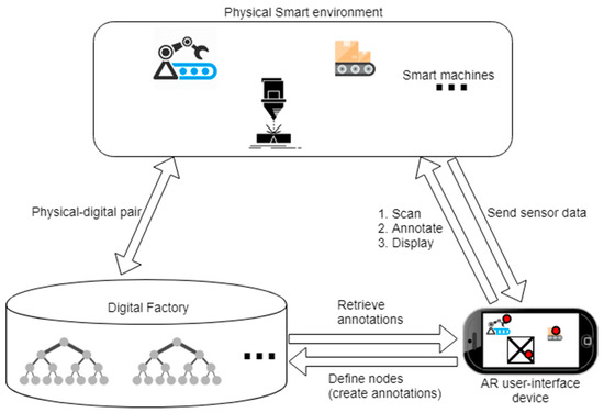
Figure 1.
The framework of user-centric augmented reality (AR) annotation highlighting the interaction between a physical smart environment, digital factory, and AR user-interface device.
The physical smart environment comprises sensors that have networking capability. Usually, the sensors report data to a control room. However, when a worker is working on-site, a direct mapping of data through the AR interface can provide instant feedback to and enhance efficiency of the worker. It is necessary to have 3D CAD models of targeted machines to fully utilize the proposed AR annotation tool, so that annotations can be placed onto the internal parts within a machine. However, the system is able to operate with limited functionalities for a traditional manufacturing environment without digital sensors nor CAD models. The built-in scanning module can map a physical object so that text, audio, and image annotations can still be placed into the context.
An AR user-interface device refers to a viewing device that is mobile and interactive. In this research, a consumer-level device, iPhone 8, is used to realize all the functions including 3D scanning, AR content registration, and touch-screen gestures to create and modify annotations.
The digital factory is a virtual representation of the physical environment [18]. In this work, it is simplified to a web-hosted database mainly consists of unique Extensible Markup Language (XML) files as descriptors for the smart environments. When a user defines a new annotatable smart environment, such as a factory in a new location, a new descriptor file will be created to store the annotations as linked nodes in the XML file. This tree data structure ensures scalability and easy adjustment of the annotations.
The annotation tool is designed to be user-friendly to the workers. It requires a one-time preparation, after which the annotation and adjustments can be made within the app in real-time. During the preparation phase, the user may or may not have the 3D models of the machines in the manufacturing environment. The system is designed to work for both cases. In case 1, detailed 3D models of the machines are available, and they can be added to the database directly. Since the pre-existing models are generally more detailed with knowledge of the internal structures of these machines, the user is able to annotate both externally and internally of the machines. In case 2, 3D models are not available and a scanning process is needed; the scanned models will be added to the database once the scanning is completed. As the user is only able to scan the external of the machine, it is not possible to annotate the internal structure of the machine in this case. Once the preparation is complete, the user-flow for annotation phase is shown in Figure 2.
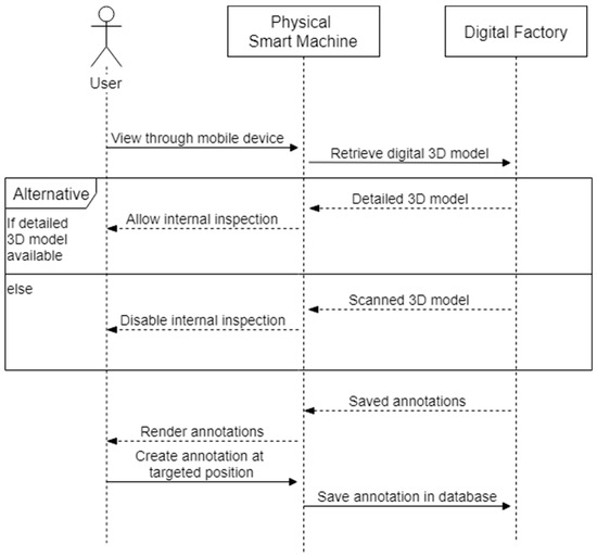
Figure 2.
The user-flow of the annotation tool.
3.1. Set-Up in the Smart Manufacturing Environment
When setting up the manufacturing environment for annotation, the user-centric annotation tool is designed to be compatible with both smart and “non-smart” traditional manufacturing environments. The common step for the preparation phase requires users to scan the environment to create a feature map of the annotatable objects of interest. The scanning is achieved using a mobile device through the world mapping and object detection functions of ARKit [19]. In ARKit implementation, the device receives motion data from an accelerometer and gyroscope constantly to compute any change in orientation and translation. This motion data is further fused with the computer vision process using camera frames to compensate any drift caused by sudden movement and cumulative errors. The computer vision process extracts and matches visual features from the camera stream. The slight change in views from the same camera stream allows the device to compute the missing depth information. This visual-inertial odometry (VIO) method, by integrating the acceleration measurement and camera translation between frames, is able to reconstruct 2D features into 3D space. The technique is well-established, and modern hardware makes it possible to be completed in real-time on a mobile device [20]. The scanning process is shown in Figure 3. Using the mobile device, the user defines a bounding box in 3D space highlighting the area in which the targeted object sits. Next, as the user moves around the object, the 3D features of the object are registered to the device and the scanning is conducted with a percentage indicating the rate of completion being displayed. Once the scanning is completed, a reference object feature file (.arobject) is created and the user will be prompted to input an object name. The *.arobject file will be sent to the database through the File Transfer Protocol (FTP). Using this 3D feature file, the system will learn to recognize the scanned object in the annotation phase. A similar scanning process will be run and the observed feature is matched against the stored feature files.
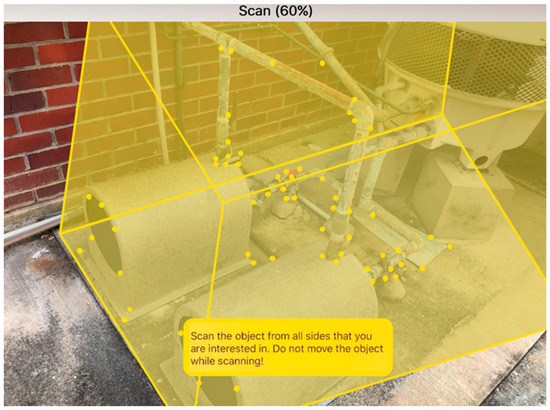
Figure 3.
The scanning user-interface. The target of interest is an exhaust system connected to a gas filter. The yellow spots highlight the three-dimensional spatial features of the target.
Once the object feature files have been created for all smart objects, the user needs to link the 3D model files to the created feature files by giving each model file (.obj) the same file name as the respective feature file (.arobject). If the user does not have the necessary 3D models, a photogrammetry solution can be used to create 3D models with the mobile device. In this work, the commercial solution provided by AutoDesk Recap is tested and used. Multiple photos are taken from all angles and uploaded to the online Recap portal (https://recap360.autodesk.com) and a 3D model file will be created for future usage.
3.2. Extend the Annotation Data Structure
The web-hosted database acts as a storage space for all the information a user needs for the annotation system. It features a tree structure which is described using a XML file. If the detailed 3D model and sensor data are available to the user, it is advised to upload the detailed model file and the uniform resource locator (URL) link of sensor data to the associated reference object description in the XML file to enrich the information available about the targeted object.
3.2.1. Data Tree Structure
A tree data structure as shown in Figure 4 is used to store all the information available for the smart manufacturing environment. The root represents the targeted environment. When the annotation tool is applied to a new environment, a new root node is created so that a user will only store/load the relevant assets in the respective tree. Level 2 is the scanned objects along with the associated sensor data links and 3D model files based on availability. New nodes are created when the user scans a new object. Level 3 is annotation nodes. Two types of annotations, namely, text and speech, are available for all objects. Sensor annotation is only available for objects with predefined URL links. When an annotation is added or deleted, the leaf of the data tree will be adjusted accordingly. In Figure 4, the sensor data is available for the exhaust gas node, and the user can create sensor annotation. A 3D model is available for the hydraulic jack, and hence annotations can be placed in the internal structure.
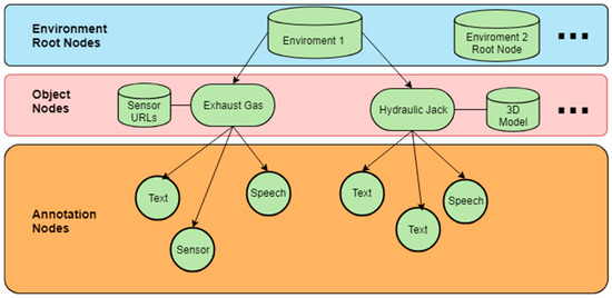
Figure 4.
The data structure featuring a tree with two object nodes, namely, the exhaust gas and hydraulic jack.
3.2.2. XML File Descriptor
Each tree structure is described by a unique XML file. Each node is defined by a pair of start-tag and end-tag. The child node tags are nested within the parent node. As an example, the descriptor for environment 1 in Figure 4 will have the structure as shown in Figure 5. In Figure 5, the details for hydraulic jack are omitted for clarity.
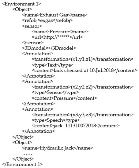
Figure 5.
The XML description file for environment 1.
The level of indention for each tag (in <>) corresponds to the level in the tree. In the <Object> node, the name of the object is declared in the <name> tag, and <refobj> refers to the saved name of the scanned reference object file. For the exhaust gas, it has a pressure sensor, the name of which is declared within the <sensor> tag and URL link saved in the <url> tag. Since it does not have a detailed 3D model, the <3Dmodel> tag is left empty. For each <Annotation> node, its 3D position is defined by the <transformation> tag. Based on the value for the <type> tag, the system will show different information in the AR interface. For “Text”, the system will show the content directly; in this case, it is a note of the last checking date. For “Sensor”, the system will look for the previously defined sensor <name> that matches the current <content> and display the reading from the URL link. For “Speech”, the <content> tag is the file name of the recorded speech. The standard file name will be the username followed by the timestamp of recording. In this case, the speech file is created by Jack on 10 July 2018, at 11:13.
3.3. Augmented Reality User Interface
The mobile device acts as an interface between a user and the web-hosted database. It is designed using Unity3D and made intuitive for novice users with basic point-and-click interactions.
3.3.1. Tracking and Authoring
When a user intends to annotate a workspace, he/she first needs to look for the target object through the mobile device. Upon successful detection, world tracking is established and the device will keep track of its own position P_device and the object’s position P_origin in the 3D space constantly. This tracking data helps to register AR information in the 3D space. The position of new annotations will be saved as relative to P_origin. In this way, when the AR session restarts, the annotation will remain at the same position relative to the object.
A user interface will be displayed as shown in Figure 6. The user interface is designed to be intuitive and provides easy access to creating different types of annotations. The top panel has four buttons, from left to right being “internal inspection”, “text”, “speech”, and “sensor” annotations. On the right of Figure 6 is the text input box for users to type the content of the annotation to be created. The “internal inspection” button toggles the 3D model overlaying on the physical object. In this case the user is able to see the depth of the piston and screws when toggled on. The three types of annotation buttons correspond to the annotation types that are defined in the XML file descriptor as explained in Section 3.2.2. A solid blue color is added to ensure visibility of buttons when the background is changing.
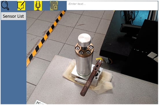
Figure 6.
The user-interface for annotation.
When adding an annotation, the user clicks to select the desired type of annotation. The chosen button will grey out. Now, the user can click on the point of interest P_hit on the object through the main view, and the corresponding annotation template will be displayed. The relative position between P_hit and P_origin is calculated and stored in the <transformation> tag, and in this way the annotation is attached to the object and can be restored in future sessions. The user can now change the text content or record a speech and move the annotation field by dragging to a more convenient location. In Figure 6, the top panel provides tools for creating three types of annotation and internal inspection. The user can see and annotate the physical environment through the main view. Currently the sensor type is selected, and a dropdown list is shown on the left. Based on the XML description, there is no available sensor link for the hydraulic jack.
3.3.2. Three Types of Annotations
The three types of annotations serve different purposes as shown in Table 1. Since the annotation is created by a user, he/she has the freedom to choose the most suitable type of annotations based on the context. Short and simple notes can be displayed directly while long instructions can be stored as speech and be replayed as needed. Sensor data can be put at hand to monitor the machine status while the physical sensor itself may be hidden in an unreachable space. The flexibility and contextual awareness is ensured by the user and the content can be easily referred to in any situations.

Table 1.
Use case for text, speech, sensor type annotations.
4. Operation Scenario
To illustrate the workflow with the proposed annotation system, two scenarios highlighting the assistance and interaction of a novice mechanical engineer are discussed in this section.
In scenario 1, the engineer is required to apply lubrication to a hydraulic jack for the first time. The object has been scanned previously and the engineer uses a smartphone to look at the previously added annotations as shown in Figure 7. Although he/she does not have prior knowledge of the object, the user can receive basic instructions from the annotations to work more efficiently. A text note was added showing the lubrication was last applied on 07/08/2018. With internal inspection toggled, he/she can see the lubrication is applied on the piston inside the cylinder, rather than the handle. A side note helps the user to identify that a hex key with dimension M6 is needed to remove the cylinder, such that he/she does not need to try out different keys. A voice recording by a previous worker Jack on the procedures of how to use the handle properly is also available for his/her reference. The engineer can touch the annotation and the speech will be played.
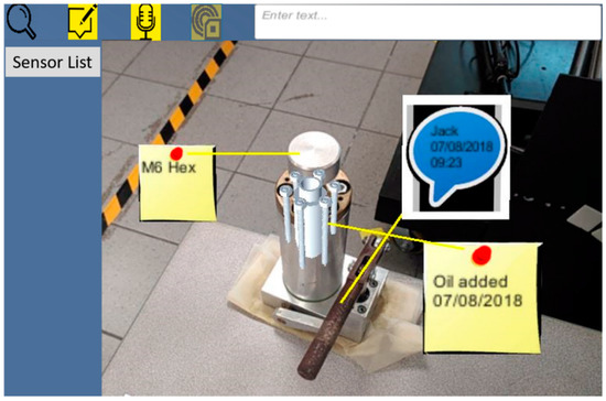
Figure 7.
The previously created annotations for the hydraulic jack.
Once the task is completed, the engineer will adjust the current annotation based on the new status. He/she first chooses the logging annotation by clicking the annotation and modifies the date to the current date by typing in the top right input field. Next, he/she removes the old voice recording by holding the speech annotation. A new speech input by the engineer is created by selecting the speech annotation type on the top panel and touching the hydraulic jack handle in the view. The system will start to record the user’s current speech. Meanwhile, the web-hosted XML file is being updated to reflect the new changes. Upon completion, the new annotations are created as shown in Figure 8. Note even when viewing from a different angle, all the annotations will always face the user for better readability.
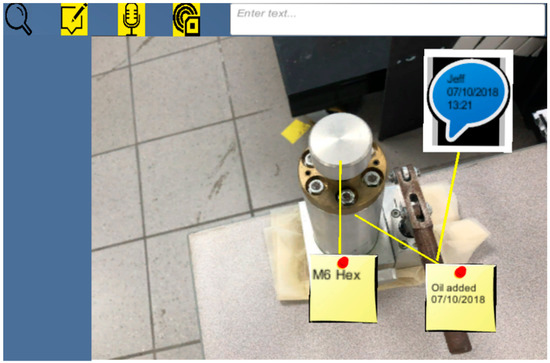
Figure 8.
The new annotations after the job is carried out by the engineer.
In Scenario 2, the pressure for the exhaust gas system needs to be examined. Usually the inspection is performed at the control center, where numerous pressure sensors are labelled by numbers. If one sensor reports a gas leakage, it is hard for a novice engineer to identify the exact location of the leakage. With the help of previously created AR annotations, the engineer is able to inspect immediately the real-time pressure for the pipe that is near his/her presence. As shown in Figure 9, the pipe in the top of the view shows a pressure that is significantly lower than the normal value. The engineer can carry out further examination based on this information. As the work progresses, the user can monitor the real-time data changes to ensure the leakage is resolved.
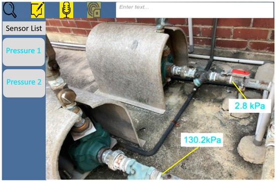
Figure 9.
The sensor annotation has been directly mapped to the pipe to help the user identify leakage. Since the sensor URL link is defined in the XML file, the left panel shows the available sensors that the user can adjust if he/she wishes.
5. Conclusions and Future Work
This paper has described a framework for user-creatable AR annotations to author useful and relevant information and make them available and easy to interact with. To help the industry adopt the AR technology, the system is built on a cost-effective device and minimum prior training is required to use the tool. Fundamentally, user-creation reduces the information redundancy which is commonly seen in AR systems designed by third party programmers. The user understands the context, and hence he/she will be able to create relevant information that is constantly available at hand. The system builds upon the infrastructure that is becoming increasingly more available as the industry moves towards smart manufacturing, such that the AR annotations can include not only static text but also real-time data. From a wider manufacturing perspective, the proposed solution can be adopted by all types of manufacturing environments and the users can customize the usage based on the specific needs. The created content can be preserved and reused more efficiently than traditional information carrier.
There are certain limitations in the current system. In the scanning phase, the target object should have clear, stable visual details. In the annotation phase, an object to be detected must also have the same shape as the scanned reference object. Rigid objects work better for detection than soft bodies or items that can bend, twist, fold, or otherwise change shape. Detection works best when the lighting conditions for the real-world object to be detected are similar to those in which the original objects were scanned. Insufficient lighting, such as within a dark warehouse, may cause the tracking to fail. Consistent indoor lighting in manufacturing environment helps the system to perform reliably in most cases.
The system can be further developed to incorporate multiuser interaction, where engineers, managers, and designers can share knowledge and collaborate in real-time based on the annotations in the same environment. In addition to sensor data, the functionality of the system can be extended to execute operations through controlling actuators and simple commands. In this way, the annotation tool becomes active and can build more powerful applications, such as shortcuts of a sequence of operations.
Above all, the user-creatable AR annotation tool addresses the gap between research and industrial applications. It is hoped that the system can be tested in more manufacturing environments and spur further interest to help push other AR technologies into real-life success.
Author Contributions
Conceptualization, F.H., S.K.O. and A.Y.C.N.; Methodology, F.H.; Software, F.H.; Writing-Original Draft Preparation, F.H.; Writing-Review and Editing, F.H., S.K.O. and A.Y.C.N.; Supervision, S.K.O. and A.Y.C.N.
Funding
This research received no external funding.
Conflicts of Interest
The authors declare no conflict of interest.
References
- Kang, H.S.; Lee, J.Y.; Choi, S.; Kim, H.; Park, J.H.; Son, J.Y.; Noh, S.D. Smart manufacturing: Past research, present findings, and future directions. Int. J. Precis. Eng. Manuf.-Green Tech. 2016, 3, 111–128. [Google Scholar] [CrossRef]
- Johansson, P.E.; Moestam, L.; Fast-Berglund, Å. Use of Assembly Information in Global Production Networks. In Proceedings of the International Conference on Flexible Automation and Intelligent Manufacturing (FAIM 2015), Wolverhampton, UK, 23–26 June 2015; Volume 1, pp. 258–265. [Google Scholar]
- Nee, A.; Ong, S.; Chryssolouris, G.; Mourtzis, D. Augmented reality applications in design and manufacturing. CIRP Annals. 2012, 61, 657–679. [Google Scholar] [CrossRef]
- Khan, A.; Turowski, K. A Survey of Current Challenges in Manufacturing Industry and Preparation for Industry 4.0. In Advances in Intelligent Systems and Computing; Springer: Cham, Switzerland, 2016; pp. 15–26. [Google Scholar]
- Onori, M.; Oliveira, J.B. Outlook report on the future of European assembly automation. Assembly Automation 2010, 30, 7–31. [Google Scholar] [CrossRef]
- Constantinescu, C.; Francalanza, E.; Matarazzo, D. Towards Knowledge Capturing and Innovative Human-system Interface in an Open-source Factory Modelling and Simulation Environment. Procedia CIRP 2015, 33, 23–28. [Google Scholar] [CrossRef]
- Feiner, S.; Henderson, S. Exploring the Benefits of Augmented Reality Documentation for Maintenance and Repair. IEEE Trans. Visual. Comput. Graphics 2011, 17, 1355–1368. [Google Scholar]
- Goto, M.; Uematsu, Y.; Saito, H.; Senda, S.; Iketani, A. Task support system by displaying instructional video onto AR workspace. In Proceedings of the 2010 IEEE International Symposium Mixed Augmented Reality, Seoul, South Korea, 13–16 October 2010; pp. 83–90. [Google Scholar]
- Ott, R.; Thalmann, D.; Vexo, F. Haptic feedback in mixed-reality environment. Vis Comput. 2007, 23, 843–849. [Google Scholar] [CrossRef]
- Lee, G.A.; Nelles, C.; Billinghurst, M.; Kim, G.J. Immersive Authoring of Tangible Augmented Reality Applications. In Proceedings of the Third IEEE and ACM International Symposium on Mixed and Augmented Reality, Arlington, VA, USA, 5 November 2004; pp. 172–181. [Google Scholar]
- Mooslechner, S.; Zollmann, S.; Degendorfer, C.; Reitmayr, G.; Schmalstieg, D.; Langlotz, T. Sketching up the world: in situ authoring for mobile Augmented Reality. Pers. Ubiquit. Comput. 2011, 16, 623–630. [Google Scholar]
- Neumann, U.; Majoros, A. Cognitive, performance, and systems issues for augmented reality applications in manufacturing and maintenance. In Proceedings of the IEEE 1998 Virtual Reality Annual International Symposium (Cat. No.98CB36180), Atlanta, GA, USA, 14–18 March 1998; pp. 4–11. [Google Scholar]
- Wang, X.; Ong, S.K.; Nee, A.Y.C. A comprehensive survey of augmented reality assembly research. Adv. Manuf. 2016, 4, 1–22. [Google Scholar] [CrossRef]
- Novak-Marcincin, J.; Barna, J.; Janak, M.; Novakova-Marcincinova, L. Augmented Reality Aided Manufacturing. Procedia. Comput. Science 2013, 25, 23–31. [Google Scholar] [CrossRef]
- Zhu, J.; Ong, S.K.; Nee, A.Y.C. An authorable context-aware augmented reality system to assist the maintenance technicians. Int. Adv. Manuf. Technol. 2012, 66, 1699–1714. [Google Scholar] [CrossRef]
- Gattullo, M.; Scurati, G.W.; Fiorentino, M.; Uva, A.E.; Ferrise, F.; Bordegoni, M. Towards augmented reality manuals for industry 4.0: A methodology. Robot. Comput.-Integr. Manuf. 2019, 56, 276–286. [Google Scholar] [CrossRef]
- He, F.; Ong, S.K.; Nee, A.Y.C. Mobile Augmented Reality Collaborative Real-Time Annotation Tool for Smart Ubiquitous Objects. Available online: http://ebooks.iospress.nl/volumearticle/50116 (accessed on 13 February 2019).
- Westkämper, E. Digital Manufacturing in the Global Era. Digital Enterprise Technol. 2007, 3–14. [Google Scholar] [CrossRef]
- Apple Inc. Arkit—Apple Developer. 2018. Available online: https://developer.apple.com/arkit/ (accessed on 11 November 2018).
- Li, P.; Qin, T.; Hu, B.; Zhu, F.; Shen, S. Monocular Visual-Inertial State Estimation for Mobile Augmented Reality. In Proceedings of the 2017 IEEE International Symposium on Mixed and Augmented Reality (ISMAR), Nantes, France, 9–13 October 2017; pp. 11–21. [Google Scholar]
© 2019 by the authors. Licensee MDPI, Basel, Switzerland. This article is an open access article distributed under the terms and conditions of the Creative Commons Attribution (CC BY) license (http://creativecommons.org/licenses/by/4.0/).