
Analysis of the Relationship between GM and IMO Intact Stability Parameters to Propose Simple Evaluation Methodology


Abstract
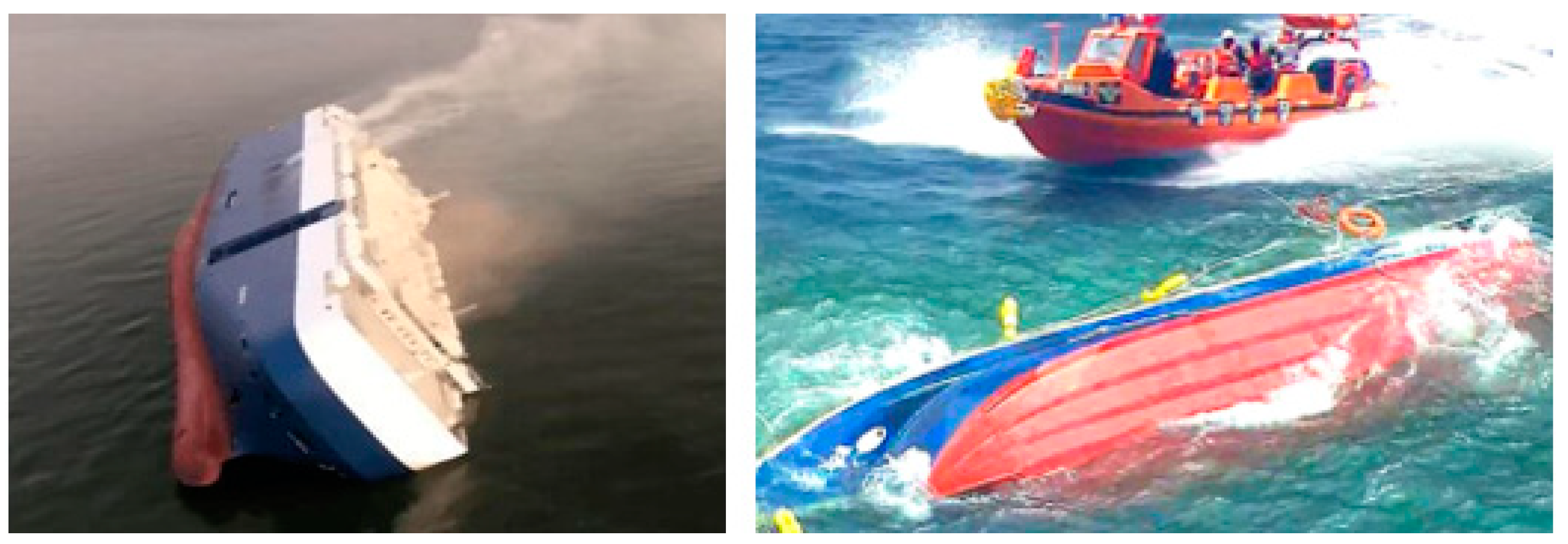
1. Introduction
2. Model Ships and Loading Conditions
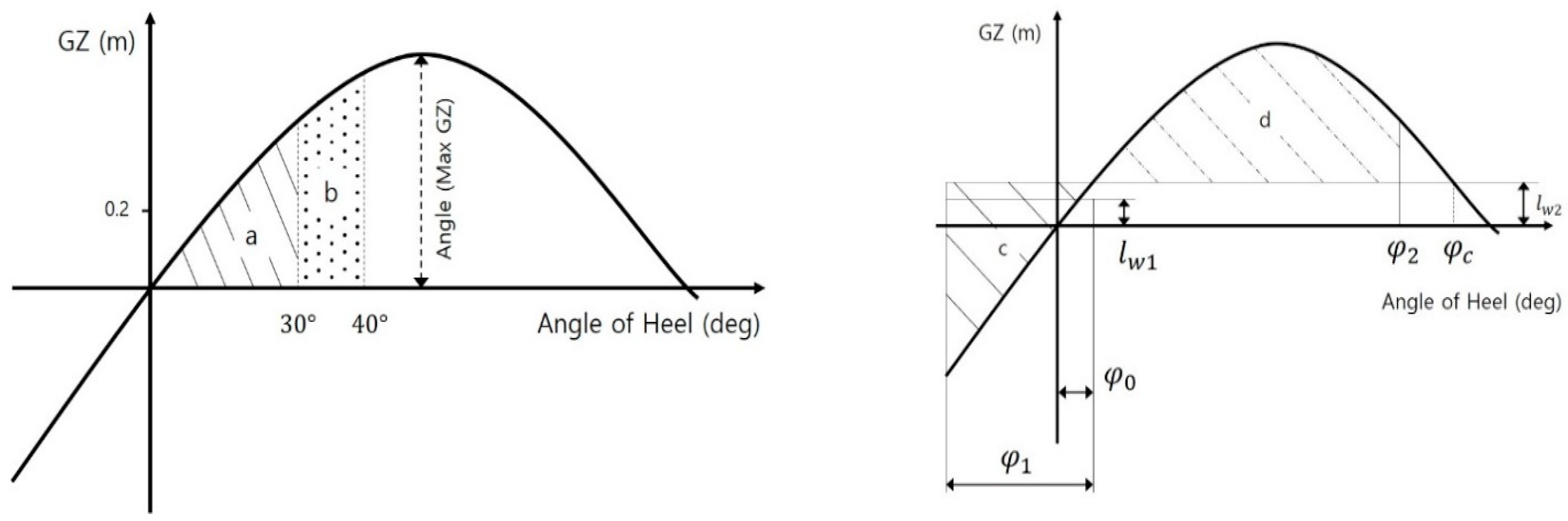
3. Parameters of IMO Intact Stability Regulations
- GM (Metacentric Height): The height from the center of gravity to the transverse metacenter, taking into account the influence of the free surface of the liquid.
- : The righting arm at 30° of the heeling angle.
- : The angle at which the GZ reaches the largest value in the range.
- : The area of “a” under GZ curve between 0° and 30° of the heeling angle.
- : The area of “b” between 30° and 40° (or flooding angle, whichever is less).
- : The area of “a + b” between 0° and 40° (or flooding angle, whichever is less).
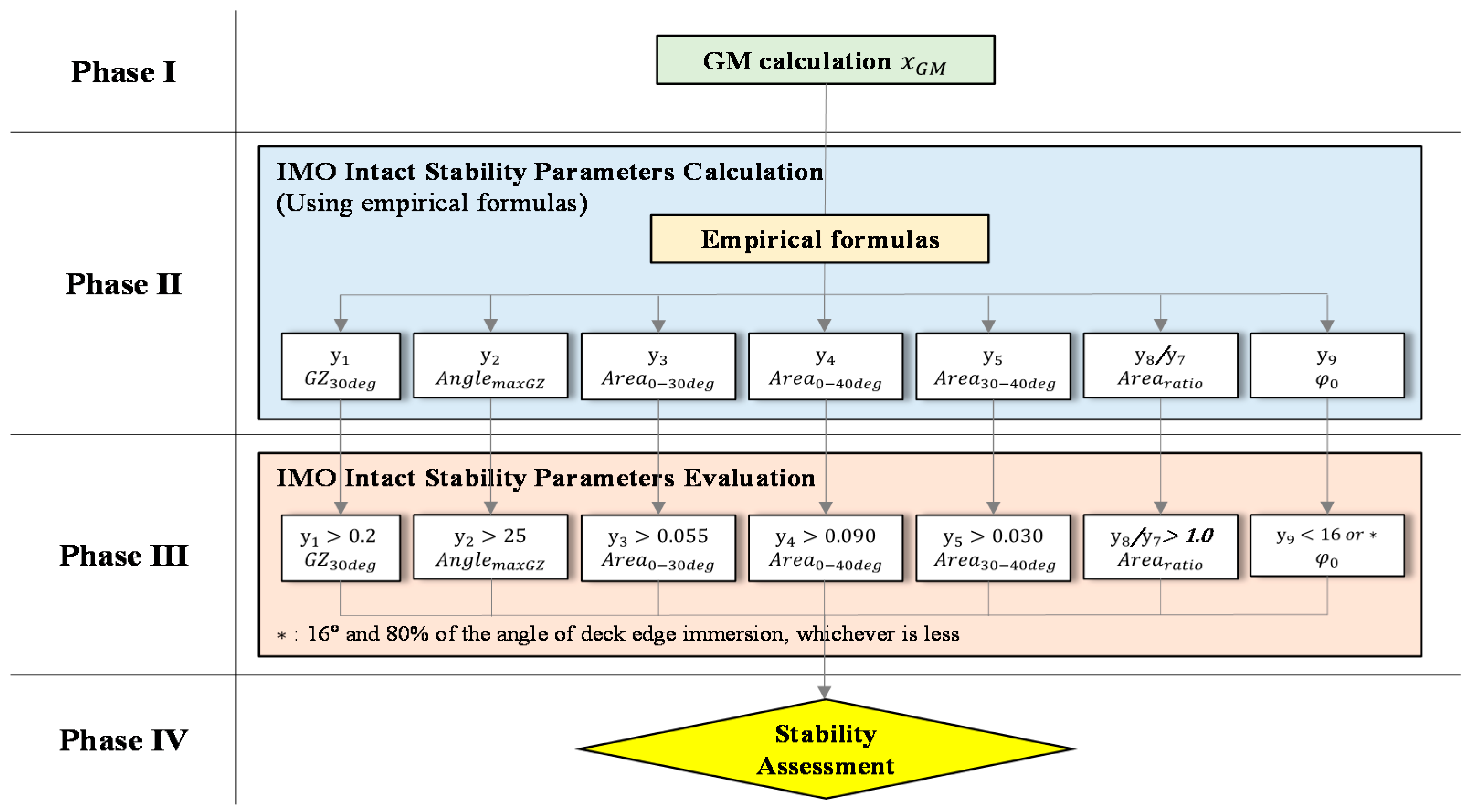
4. SEMIS
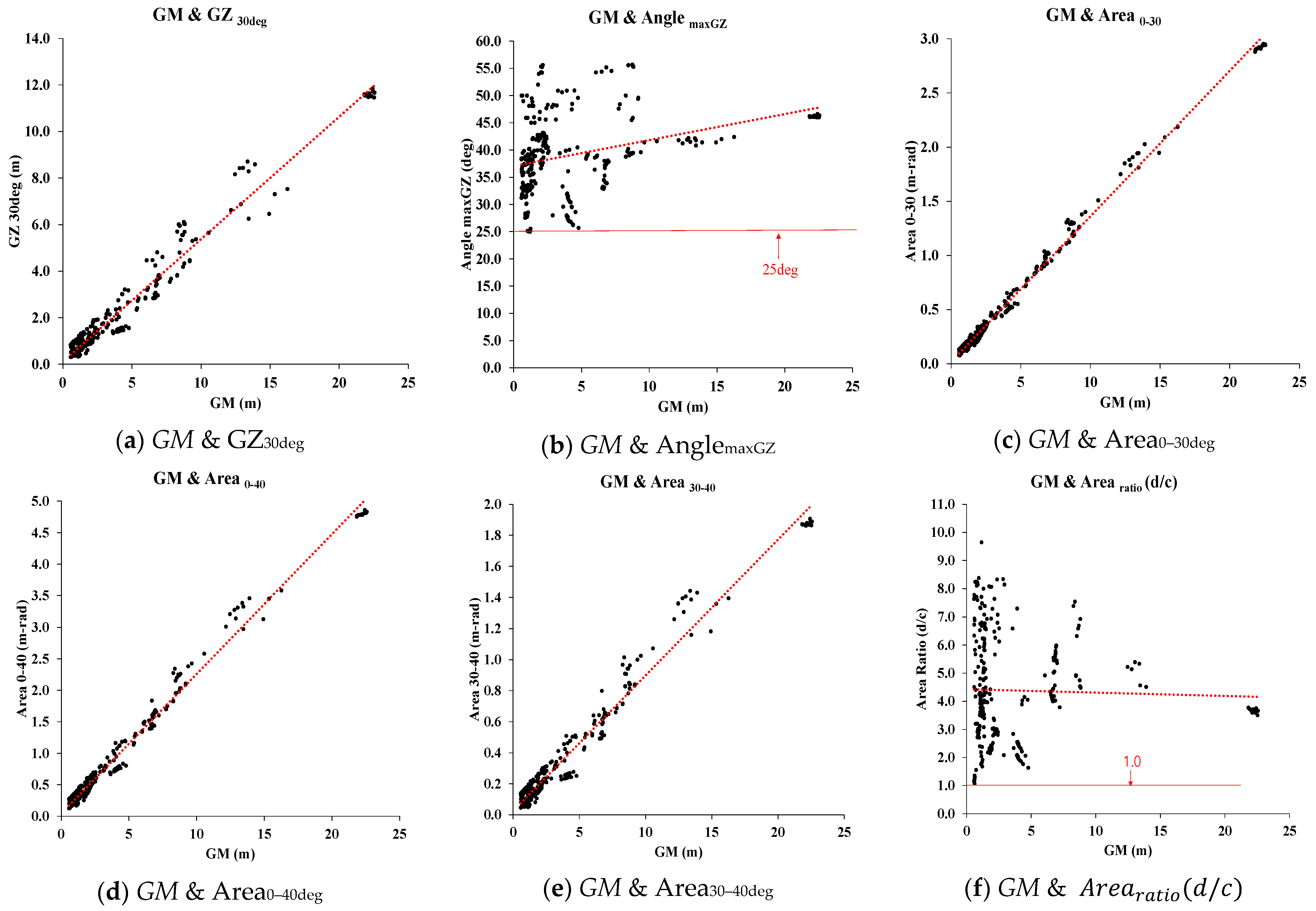
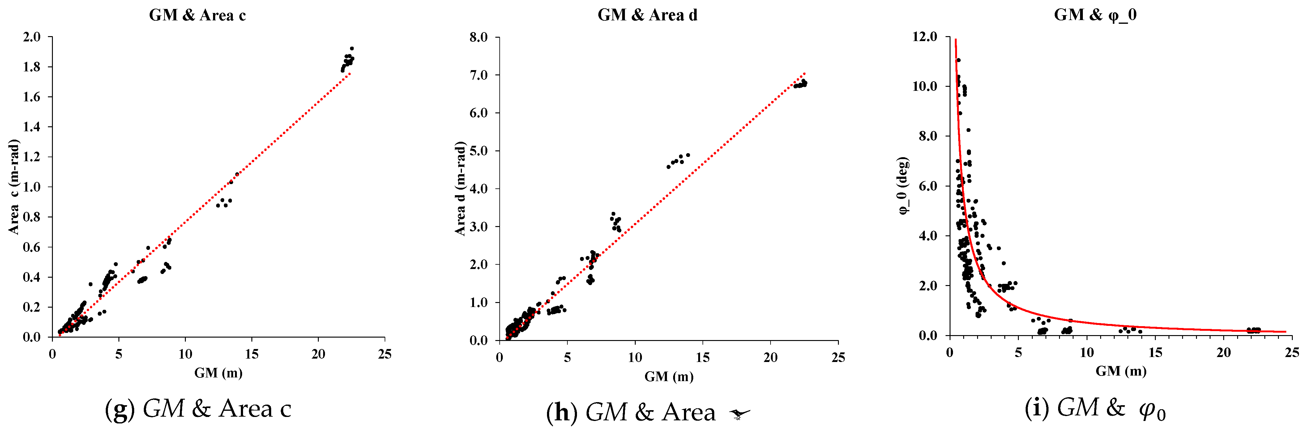
4.1. Derivation of Empirical Formulas of SEMIS
4.2. Analysis Empirical Formulas
4.3. Concept of SEMIS
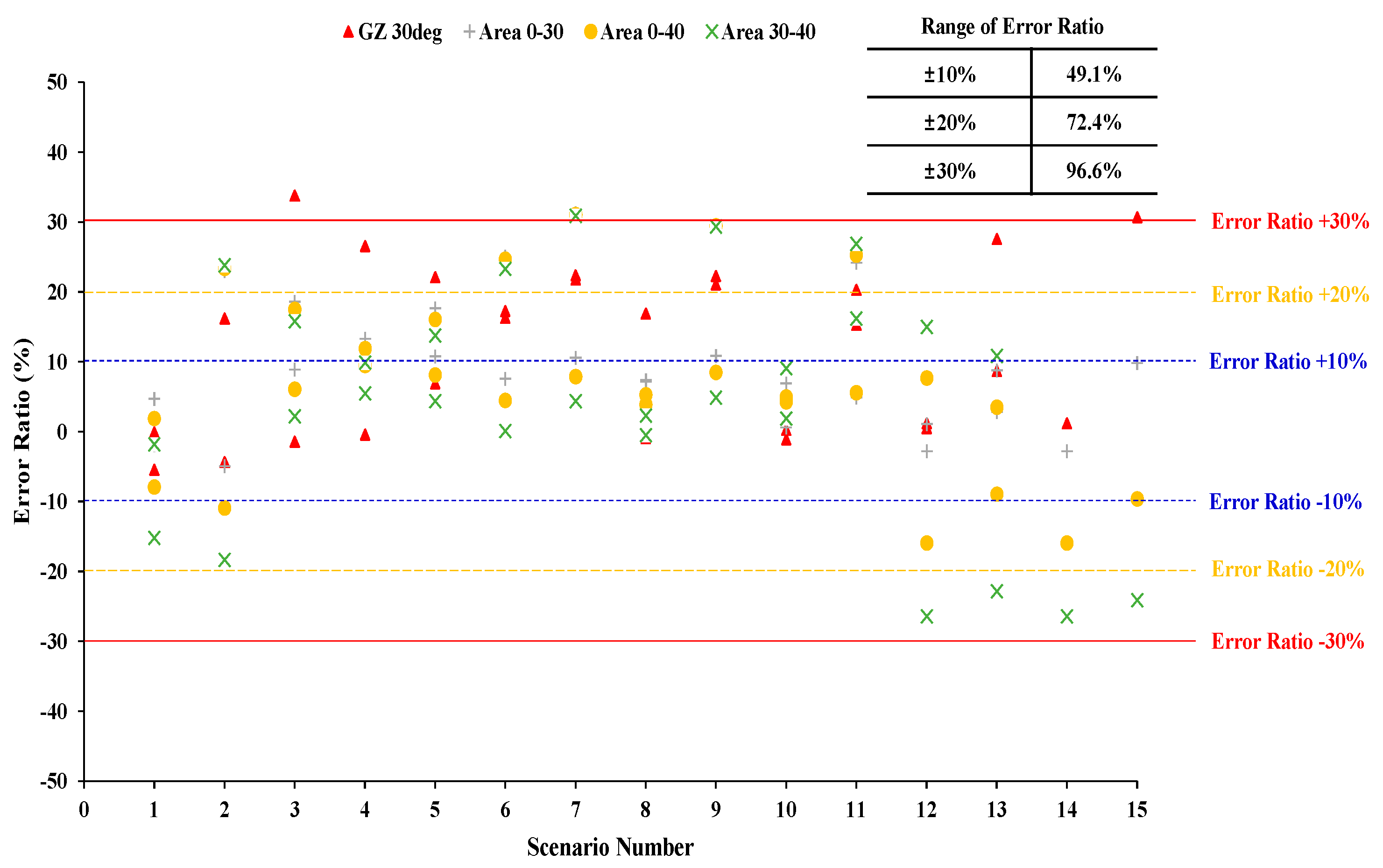
5. Verification of SEMIS
5.1. Model Ships for the Verification
5.2. Results and Discussion
6. Conclusions
- The SEMIS comprises four phases (Calculating GM, Calculating Parameters, Evaluating Parameters, and Stability Assessment in sequence) for evaluating IMO intact stability parameters, as shown in Figure 4. From the point of view of ship operators who are working in ships without ship loading software or equipment and have relatively less knowledge for evaluating the risk of ships’ stability performance, SEMIS is considered an effective supplementary method.
- The developed SEMIS efficiently evaluates the ships’ stability using only GM, whether compliant with the IMO regulations or not. As shown in Table 9, SEMIS perfectly evaluates four insufficient loading conditions in a total of 28 scenarios.
- In further studies, additional types of ships and loading conditions will be considered in order to improve the reliability of the empirical formulas of SEMIS. Additionally, experiments using a sensor that measures the roll period of a ship, followed by evaluations using SEMIS, will be carried out in future studies.
Author Contributions
Funding
Conflicts of Interest
Nomenclature
| IMO | International Maritime Organization |
| SEMIS | Simple Evaluation Methodology for Intact Stability |
| GM | Metacentric height |
| KG | Height of the ship’s center of gravity above the keel |
| KM | Height of metacenter above the keel |
| Symbols | |
| (GM) | GM (m) |
| () | Righting arm at 30° of the heeling angle (m) |
| Angle at which the GZ reaches the largest value in the range (deg) | |
| Area of GZ curve between 0° and 30° of the heeling angle (m-rad) | |
| Area of GZ curve between 0°and 40° (or flooding angle, whichever is less) (m-rad) | |
| Area of GZ curve between 30°and 40° (or flooding angle, whichever is less) (m-rad) | |
| () | Ratio of area d divided by area c |
| () | Area of GZ curve of the weather criterion between and (m-rad) |
| ( | Area of GZ curve of the weather criterion between and (m-rad) |
| ( | Heeling angle in steady wind pressure (deg) |
References
- Splash247 Four Crew Missing after Glovis Car Carrier Capsizes at Port of Brunswick. Available online: https://splash247.com/four-crew-missing-after-glovis-car-carrier-capsizes-off-port-of-brunswick/ (accessed on 27 March 2021).
- SBS Dolgorae Ho Fishing Vessel Was Capsized and Lost All Crews. Available online: https://news.sbs.co.kr/news/endPage.do?news_id=N1003161087 (accessed on 27 June 2021).
- IMO. Recommendation on a Severe Wind and Rolling Criterion (Weather Criterion) for the Intact Stability of Passenger and Cargo Ship of 24 Metres in Length and over Resolution A.562; IMO: London, UK, 1985. [Google Scholar]
- IMO. Code of Intact Stability for All Ships Covered by IMO Instruments Resolution A.749 (18); IMO: London, UK, 1993. [Google Scholar]
- IMO. Code of Intact Stability for All Ships Covered by IMO Instruments Resolution MSC.267 (85); IMO: London, UK, 2008. [Google Scholar]
- Pierrottet, E. Standards of stability for ships. Trans. Inst. Nav. Archit. 1935, 77, 208–222. [Google Scholar]
- Rahola, J. The Judging of the Stability of Ships and the Determination of the Minimum Amount of Stability Especially Considering the Vessels Navigating Finnish Waters; Faculty of Mechanical, Maritime and Materials Engineering: Aalto, Finland, 1939. [Google Scholar]
- Yamagata, M. Standard of stability adopted in japan. Trans. Inst. Navy. Archit. 1959, 417–443. [Google Scholar]
- Goldberg, L.L.S. Stability and buoyancy criteria for U.S. naval surface ships. Trans. Am. Soc. Nav. Arch. Mar. Eng. 1962, 418–458. [Google Scholar]
- Mantari, J.L.; Ribeiro E Silva, S.; Guedes Soares, C. Intact stability of fishing vessels under combined action of fishing gear, beam waves and wind. Ocean Eng. 2011. [Google Scholar] [CrossRef]
- Hu, Y.; Tang, J.; Xue, S.; Liu, S. Stability criterion and its calculation for Sail-Assisted ship. Int. J. Nav. Archit. Ocean Eng. 2015. [Google Scholar] [CrossRef]
- Deybach, F. Intact Stability Criteria for Naval Ships. Master’s Thesis, Ecole Nationale Superieure des Ingenieurs des Etudes et Techniques d’Armement, Brest, France, 1997. [Google Scholar]
- Marutheri Parambath, J. Development of Intact Stability Weather Criterion Applicable to River-Sea Vessels. Master’s Thesis, University of Rostock, Rostock, Germany, 2019. [Google Scholar]
- Brown, D.; Witz, J. Estimation of vessel stability at sea using roll motion records. Trans. RINA 1996, 130–146. [Google Scholar]
- Terada, D.; Tamashima, M.; Nakao, I.; Matsuda, A. Estimation of metacentric height using onboard monitoring roll data based on time series analysis. J. Mar. Sci. Technol. 2019. [Google Scholar] [CrossRef]
- Santiago Caamaño, L.; Míguez González, M.; Díaz Casás, V. On the feasibility of a real time stability assessment for fishing vessels. Ocean Eng. 2018. [Google Scholar] [CrossRef]
- Santiago Caamaño, L.; Galeazzi, R.; Nielsen, U.D.; Míguez González, M.; Díaz Casás, V. Real-time detection of transverse stability changes in fishing vessels. Ocean Eng. 2019. [Google Scholar] [CrossRef]
- Ariffin, A.; Laurens, J.M.; Mansor, S. Real-time evaluation of second generation intact stability criteria. In Proceedings of the RINA, Royal Institution of Naval Architects—Smart Ship Technology 2016, London, UK, 26–27 January 2016. [Google Scholar]
- Wolfson Unit. Evaluation of Existing Criteria; Wolfson Unit MTIA: Southampton, UK, 2005. [Google Scholar]
- Wolfson Unit. Simplified Presentation of Fishing Vessels Stability Information for Vessels 12 m Registered Length and Over; Wolfson Unit MTIA: Southampton, UK, 2006. [Google Scholar]
- Deakin, B. Collating evidence for a universal method of stability assessment or guidance. Trans. R. Inst. Nav. Archit. Part A Int. J. Marit. Eng. 2010. [Google Scholar] [CrossRef]
- González, M.M.; Sobrino, P.C.; Álvarez, R.T.; Casás, V.D.; López, A.M.; Peña, F.L. Fishing vessel stability assessment system. Ocean Eng. 2012. [Google Scholar] [CrossRef]
- Im, N.-K.; Hwang, S.; Choe, H. Development of Stability Index for Vessel Operators Support System. J. Korean Soc. Mar. Environ. Saf. 2018. [Google Scholar] [CrossRef]
- Nam-Kyun, I.M.; Hun, H.C. A quantitative methodology for evaluating the ship stability using the index for marine ship intact stability assessment model. Int. J. Nav. Archit. Ocean Eng. 2021, 13, 246–259. [Google Scholar]


| No. | Model Ships | Length B. P. (m) | Breadth (m) | Full Displacement (ton) |
|---|---|---|---|---|
| 1 | B-1 | 264.0 | 45.0 | 169,406.3 |
| 2 | B-2 | 300.4 | 50.0 | 233,117.3 |
| 3 | B-3 | 78.7 | 14.0 | 5145.7 |
| 4 | B-4 | 107.2 | 18.2 | 9666.9 |
| 5 | C-1 | 210.9 | 30.0 | 51,658.0 |
| 6 | C-2 | 248.0 | 32.3 | 68,056.4 |
| 7 | C-3 | 244.0 | 37.3 | 84,028.1 |
| 8 | C-4 | 137.0 | 22.6 | 17,105.6 |
| 9 | TK-1 | 142.6 | 24.2 | 25,811.4 |
| 10 | TK-2 | 322.0 | 60.0 | 364,796.0 |
| 11 | P-1 | 171.0 | 27.0 | 16,044.7 |
| 12 | P-2 | 138.5 | 24.1 | 11,135.0 |
| 13 | P-3 | 132.0 | 22.0 | 9907.5 |
| 14 | TR-1 | 104.0 | 17.8 | 6434.6 |
| 15 | TR-2 | 120.0 | 19.4 | 9122.2 |
| 16 | TR-3 | 94.0 | 15.6 | 4626.7 |
| 17 | TR-4 | 93.0 | 14.5 | 4318.8 |
| 18 | R-1 | 86.0 | 18.0 | 6392.3 |
| 19 | G-2 | 99.2 | 19.5 | 6580.4 |
| Model Ships | Number of Scenarios | Range of Displacement (ton) | Range of Cb |
|---|---|---|---|
| Bulk carrier ship | 46 | 3640.5~233,118.5 | 0.731~0.841 |
| Container ship | 93 | 8276.2~84,257.0 | 0.545~0.662 |
| Tanker ship | 65 | 13,589.2~364,896.0 | 0.728~0.813 |
| Passenger ship | 72 | 1153.8~16,044.7 | 0.475~0.765 |
| Training ship | 38 | 3549.8~9122.2 | 0.538~0.597 |
| Research ship | 18 | 5413.7~6392.3 | 0.584~0.616 |
| General cargo ship | 4 | 3498.5~6580.2 | 0.731~0.785 |
| Stability Parameter | Criteria |
|---|---|
| 0.150 m | |
| 0.200 m | |
| 25 deg | |
| 0.055 m-rad | |
| 0.090 m-rad | |
| 0.030 m-rad | |
| 1.0 | |
| 16° and 80% of the angle of deck edge immersion, whichever is less |
| No. | Stability Parameter | Empirical Formula According to GM | |
|---|---|---|---|
| 1 | 0.9611 | ||
| 2 | 0.0972 | ||
| 3 | 0.9942 | ||
| 4 | 0.9870 | ||
| 5 | 0.9676 | ||
| 6 | 0.0009 | ||
| 7 | Area c | 0.9680 | |
| 8 | Area d | 0.9741 | |
| 9 | 0.58029 |
| No. | Type of Ship | Compliance with IMO Reg | GM (m) | AnglemaxGZ (deg) |
|---|---|---|---|---|
| 1 | P | x | 0.10 | 36.50 |
| 2 | P | x | 0.20 | 37.02 |
| 3 | P | x | 0.30 | 37.51 |
| 4 | P | x | 0.40 | 37.51 |
| 5 | G | x | 0.10 | 49.48 |
| 6 | G | x | 0.16 | 48.91 |
| 7 | TR | x | 0.10 | 36.50 |
| 8 | TR | x | 0.13 | 38.41 |
| 9 | TR | x | 0.20 | 37.00 |
| 10 | TR | x | 0.30 | 37.50 |
| 11 | P | o | 0.50 | 38.00 |
| 12 | P | o | 0.60 | 38.50 |
| 13 | TR | o | 0.40 | 38.50 |
| 14 | C | o | 0.56 | 33.05 |
| 15 | C | o | 0.57 | 38.40 |
| 16 | C | o | 0.58 | 38.46 |
| 17 | R | o | 0.57 | 31.20 |
| Items | General Cargo Ship | Training Ship |
|---|---|---|
| Length O. A. | 83.4 m | 133.0 m |
| Length B. P. | 75.2 m | 120.0 m |
| Breadth (B) | 14.0 m | 19.4 m |
| Draft (d) | 6.1 m | 6.4 m |
| Full Displacement | 5646.8 ton | 9122.2 ton |
| 0.732 | 0.553 |
| Scenario Number | Compliance with IMO Reg | GM (m) [0.15] | GZ30deg (m) [0.20] | AnglemaxGZ (deg) [25.0] | Area0–30 (m-rad) [0.055] | Area0–40 (m-rad) [0.090] | Area30–40 (m-rad) [0.030] | (deg) [G:11.42] [TR:11.12] | Arearatio (d/c) [1.0] | |
|---|---|---|---|---|---|---|---|---|---|---|
| General Cargo Ship | 1 | o | 1.79 | 1.06 | 51.99 | 0.27 | 0.48 | 0.22 | 1.37 | 3.01 |
| 2 | o | 1.84 | 1.13 | 53.98 | 0.28 | 0.51 | 0.23 | 1.49 | 2.43 | |
| 3 | o | 1.36 | 0.62 | 48.85 | 0.17 | 0.29 | 0.12 | 1.14 | 2.80 | |
| 4 | o | 1.33 | 0.65 | 49.48 | 0.18 | 0.31 | 0.13 | 1.26 | 3.01 | |
| 5 | o | 2.13 | 1.02 | 55.59 | 0.28 | 0.48 | 0.20 | 0.82 | 2.83 | |
| 6 | o | 2.14 | 1.06 | 55.59 | 0.29 | 0.50 | 0.21 | 0.82 | 2.51 | |
| 7 | o | 2.09 | 0.10 | 55.24 | 0.27 | 0.47 | 0.20 | 0.77 | 2.27 | |
| 8 | o | 2.09 | 1.04 | 54.21 | 0.28 | 0.49 | 0.21 | 0.82 | 2.89 | |
| 9 | o | 2.01 | 0.96 | 55.33 | 0.26 | 0.45 | 0.19 | 0.80 | 2.33 | |
| 10 | o | 1.10 | 0.69 | 48.72 | 0.17 | 0.30 | 0.13 | 7.56 | 3.58 | |
| 11 | o | 0.40 | 0.28 | 49.03 | 0.07 | 0.14 | 0.07 | 9.83 | 9.54 | |
| 12 | x | 0.10 | 0.16 | 48.25 | 0.03 | 0.08 | 0.04 | 17.86 | 2.91 | |
| 13 | x | 0.16 | 0.16 | 48.91 | 0.04 | 0.09 | 0.05 | 17.07 | 2.33 | |
| Training Ship | 1 | o | 2.33 | 1.42 | 42.45 | 0.32 | 0.55 | 0.23 | 2.50 | 3.01 |
| 2 | o | 1.89 | 0.96 | 42.62 | 0.22 | 0.38 | 0.15 | 4.30 | 2.43 | |
| 3 | o | 2.42 | 1.41 | 42.46 | 0.32 | 0.55 | 0.23 | 2.70 | 2.80 | |
| 4 | o | 2.24 | 1.30 | 43.08 | 0.29 | 0.50 | 0.21 | 3.10 | 3.01 | |
| 5 | o | 2.15 | 1.16 | 43.16 | 0.26 | 0.45 | 0.19 | 3.30 | 2.83 | |
| 6 | o | 2.04 | 1.02 | 42.73 | 0.24 | 0.40 | 0.17 | 3.70 | 2.51 | |
| 7 | o | 1.94 | 0.93 | 42.73 | 0.22 | 0.36 | 0.15 | 4.50 | 2.27 | |
| 8 | o | 2.31 | 1.34 | 41.67 | 0.31 | 0.53 | 0.22 | 2.50 | 2.89 | |
| 9 | o | 1.77 | 0.86 | 42.45 | 0.20 | 0.34 | 0.14 | 4.80 | 2.33 | |
| 10 | o | 2.43 | 1.41 | 42.10 | 0.33 | 0.56 | 0.23 | 2.30 | 2.91 | |
| 11 | o | 1.95 | 0.95 | 42.08 | 0.23 | 0.38 | 0.15 | 4.10 | 2.33 | |
| 12 | o | 0.50 | 0.38 | 48.44 | 0.09 | 0.17 | 0.08 | 10.77 | 7.71 | |
| 13 | o | 0.80 | 0.49 | 49.22 | 0.13 | 0.23 | 0.11 | 9.74 | 3.29 | |
| 14 | x | 0.10 | 0.17 | 48.24 | 0.04 | 0.08 | 0.05 | 17.87 | 2.11 | |
| 15 | x | 0.13 | 0.14 | 48.90 | 0.04 | 0.08 | 0.05 | 17.91 | 1.94 |
 : non-compliant with IMO stability regulation.
| Scenario Number | GM (m) [0.15] | GZ30deg (m) [0.20] | Error Ratio (%) | Area0–30 (m-rad) [0.055] | Error Ratio (%) | Area0–40 (m-rad) [0.090] | Error Ratio(%) | Area30–40 (m-rad) [0.030] | Error Ratio (%) | (deg) [11.42] [11.12] | Error Ratio (%) | |
|---|---|---|---|---|---|---|---|---|---|---|---|---|
| General Cargo Ship | 1 | 1.80 | 1.06 | −0.1 | 0.26 | −1.9 | 0.45 | −7.9 | 0.18 | −15.2 | 2.992 | 118.3 |
| 2 | 1.85 | 1.09 | −4.3 | 0.27 | −4.9 | 0.46 | −10.9 | 0.19 | −18.3 | 2.928 | 96.2 | |
| 3 | 1.37 | 0.84 | 33.8 | 0.21 | 18.6 | 0.35 | 17.5 | 0.14 | 15.8 | 3.747 | 229.8 | |
| 4 | 1.33 | 0.82 | 26.6 | 0.20 | 13.3 | 0.34 | 11.9 | 0.14 | 9.89 | 3.826 | 203.2 | |
| 5 | 2.14 | 1.24 | 22.1 | 0.31 | 10.8 | 0.52 | 8.1 | 0.21 | 4.4 | 2.582 | 216.4 | |
| 6 | 2.14 | 1.24 | 17.3 | 0.31 | 7.6 | 0.52 | 4.5 | 0.21 | 0.1 | 2.576 | 215.7 | |
| 7 | 2.09 | 1.21 | 21.8 | 0.30 | 10.6 | 0.51 | 7.9 | 0.21 | 4.4 | 2.632 | 240.9 | |
| 8 | 2.09 | 1.22 | 16.9 | 0.30 | 7.2 | 0.51 | 3.9 | 0.21 | −0.5 | 2.628 | 218.6 | |
| 9 | 2.01 | 1.17 | 22.3 | 0.29 | 10.9 | 0.49 | 8.5 | 0.20 | 4.9 | 2.725 | 241.5 | |
| 10 | 0.50 | 0.69 | 0.3 | 0.17 | 0.6 | 0.29 | 4.3 | 0.12 | 9.1 | 4.45 | 41.1 | |
| 11 | 0.80 | 0.33 | 15.3 | 0.08 | 4.9 | 0.14 | 5.6 | 0.06 | 16.2 | 8.71 | 11.4 | |
| 12 | 0.10 | 0.17 | 1.2 | 0.04 | −2.7 | 0.07 | −15.9 | 0.03 | −26.4 | 14.75 | −17.4 | |
| 13 | 0.16 | 0.20 | 27.6 | 0.04 | 8.8 | 0.08 | −8.9 | 0.04 | −22.8 | 12.96 | −24.1 | |
| Training Ship | 1 | 2.33 | 1.34 | −5.4 | 0.33 | 4.7 | 0.56 | 1.9 | 0.23 | −1.8 | 2.39 | −4.2 |
| 2 | 1.89 | 1.11 | 16.2 | 0.28 | 23.0 | 0.47 | 23.4 | 0.19 | 23.8 | 2.86 | −33.4 | |
| 3 | 2.42 | 1.39 | −1.4 | 0.35 | 8.9 | 0.58 | 6.1 | 0.24 | 2.2 | 2.32 | −14.1 | |
| 4 | 2.24 | 1.29 | −0.4 | 0.32 | 12.4 | 0.54 | 9.5 | 0.22 | 5.5 | 2.48 | −19.9 | |
| 5 | 2.15 | 1.24 | 6.9 | 0.31 | 17.7 | 0.52 | 16.1 | 0.21 | 13.8 | 2.57 | −22.1 | |
| 6 | 2.04 | 1.19 | 16.3 | 0.30 | 25.1 | 0.50 | 24.7 | 0.20 | 23.3 | 2.69 | −27.4 | |
| 7 | 1.94 | 1.14 | 22.4 | 0.28 | 31.3 | 0.48 | 31.1 | 0.19 | 30.9 | 2.80 | −37.8 | |
| 8 | 2.31 | 1.33 | −0.9 | 0.33 | 7.4 | 0.56 | 5.3 | 0.23 | 2.3 | 2.41 | −3.6 | |
| 9 | 1.77 | 1.05 | 21.1 | 0.26 | 29.5 | 0.44 | 29.5 | 0.18 | 29.4 | 3.03 | −36.9 | |
| 10 | 2.43 | 1.39 | −1.1 | 0.35 | 6.9 | 0.59 | 5.0 | 0.24 | 1.9 | 2.31 | 0.3 | |
| 11 | 1.95 | 1.14 | 20.3 | 0.28 | 24.2 | 0.48 | 25.3 | 0.20 | 26.9 | 2.79 | −31.9 | |
| 12 | 0.50 | 0.38 | 0.5 | 0.09 | 1.1 | 0.16 | 7.7 | 0.07 | 15.0 | 7.66 | 28.9 | |
| 13 | 0.80 | 0.54 | 8.7 | 0.13 | 2.8 | 0.22 | 3.5 | 0.09 | 10.9 | 5.63 | 42.2 | |
| 14 | 0.10 | 0.17 | 1.2 | 0.03 | −2.8 | 0.07 | −15.9 | 0.03 | −26.4 | 14.75 | −17.4 | |
| 15 | 0.13 | 0.18 | 30.7 | 0.04 | 9.8 | 0.08 | −9.6 | 0.04 | −24.1 | 13.80 | −22.9 |
: Non-compliant with IMO stability regulation,  : error ratio over 30%.
| Scenario Number | Principal Method | SEMIS | |
|---|---|---|---|
| General Cargo Ship | 1 | o | o |
| 2 | o | o | |
| 3 | o | o | |
| 4 | o | o | |
| 5 | o | o | |
| 6 | o | o | |
| 7 | o | o | |
| 8 | o | o | |
| 9 | o | o | |
| 10 | o | o | |
| 11 | o | o | |
| 12 | x | x | |
| 13 | x | x | |
| Training Ship | 1 | o | o |
| 2 | o | o | |
| 3 | o | o | |
| 4 | o | o | |
| 5 | o | o | |
| 6 | o | o | |
| 7 | o | o | |
| 8 | o | o | |
| 9 | o | o | |
| 10 | o | o | |
| 11 | o | o | |
| 12 | o | o | |
| 13 | o | o | |
| 14 | x | x | |
| 15 | x | x |
Publisher’s Note: MDPI stays neutral with regard to jurisdictional claims in published maps and institutional affiliations. |
© 2021 by the authors. Licensee MDPI, Basel, Switzerland. This article is an open access article distributed under the terms and conditions of the Creative Commons Attribution (CC BY) license (https://creativecommons.org/licenses/by/4.0/).
Share and Cite
Woo, D.; Choe, H.; Im, N.-K. Analysis of the Relationship between GM and IMO Intact Stability Parameters to Propose Simple Evaluation Methodology. J. Mar. Sci. Eng. 2021, 9, 735. https://doi.org/10.3390/jmse9070735
Woo D, Choe H, Im N-K. Analysis of the Relationship between GM and IMO Intact Stability Parameters to Propose Simple Evaluation Methodology. Journal of Marine Science and Engineering. 2021; 9(7):735. https://doi.org/10.3390/jmse9070735
Chicago/Turabian StyleWoo, Donghan, Hun Choe, and Nam-Kyun Im. 2021. "Analysis of the Relationship between GM and IMO Intact Stability Parameters to Propose Simple Evaluation Methodology" Journal of Marine Science and Engineering 9, no. 7: 735. https://doi.org/10.3390/jmse9070735
APA StyleWoo, D., Choe, H., & Im, N.-K. (2021). Analysis of the Relationship between GM and IMO Intact Stability Parameters to Propose Simple Evaluation Methodology. Journal of Marine Science and Engineering, 9(7), 735. https://doi.org/10.3390/jmse9070735