1. Introduction
The low-vibration performance design of underwater vehicles is critical to their concealment and navigation performance. For a thermodynamic underwater vehicle, the mechanical noise of the power system is the main noise source when it sails at a relatively deep depth [
1]. The source of mechanical noise is mainly excited by the operation of the power plant, which contains multiple vibration sources. These vibration may be transmitted to the outer housing of the underwater vehicle through different paths, resulting in structural vibration and noise radiation. As one of the most effective measures to mitigate vibration transmission, vibration isolators are generally utilized in the structural design of underwater vehicle power plants. Traditional vibration isolators frequently use rubber as the vibration isolation material. To facilitate installation, rubber is commonly vulcanized with the metal frame to form an independent vibration isolator. Engineering practice shows that the transmission of vibration in the power system can be effectively mitigated by selecting appropriate rubber materials. However, rubber is prone to aging and shows poor impact resistance during long-term storage. In addition, the installation space of a vibration isolator is extremely limited due to the cramped space inside an underwater vehicle. The metal skeleton in the rubber vibration isolator occupies a part of the installation space of the elastic material, thereby reducing the volume of vibration isolation materials. Therefore, it is urgent to develop some new types of vibration isolators that could employ more vibration isolation materials. In addition, a reasonable and accurate evaluation of the vibration isolation effectiveness of isolators in underwater vehicles is also extremely important.
The dynamic vibration isolation system of an underwater vehicle is a typical elastic foundation vibration isolation. The power plant occupies most of the mass of a power system. Compared with the power plant, the outer housing of the vehicle is lighter and thinner. There is an inevitable vibration coupling between the power plant, the vibration isolator and the outer housing. The coupling, on the one hand, affects the vibration isolation effectiveness; on the other hand, it produces external sound radiation. The classic model of a vibration isolation system is the mass-spring-foundation model. In this model, the basic vibration isolation structure is commonly regarded as a rigid structure with infinite impedance. However, actual infrastructures often do not meet the above assumptions. For a basic structure that does not meet the rigidity assumption, an elastic foundation vibration isolation model has been developed. Scholars considered the actual structural form and analyzed the vibration characteristics of a vibration isolation system with beams [
2,
3], plates [
4,
5,
6] and even cylindrical shells [
7,
8,
9,
10] by simplifying the basic structure. Some scholars considered the problem of non-linearity [
11,
12]. Flotow [
13] summarized and proposed the elastic foundation–rigid equipment approximate modeling method by analyzing and collating the modeling methods of mechanical equipment–vibration isolation system basic structure. The finite element method is widely adopted to build a vibration isolation system model for more complex infrastructure forms [
14]. Experimental research occupies an important part in the research and design of vibration isolators [
15,
16,
17,
18,
19]. There are many evaluation methods for the vibration effectiveness of elastic foundation isolation system, which include power flow transfer spectrum [
20], the maximum and minimum singular values of the effective ratio matrix of force and velocity [
21], the transfer rate matrix of force and velocity [
22] and the force transmission rate [
23,
24,
25]. In underwater vehicles, the purpose of an isolation system is to mitigate the vibration transmission of the equipment to the foundation and reduce the vibration energy level of the foundation. For an isolator system in engineering terms, the biggest concern is the vibration energy level transmitted to the foundation after the isolator, that is, the vibration response of the foundation in the isolation system. Therefore, the insertion loss and vibration level drop are often utilized as indexes in the evaluation of the effectiveness of an underwater vehicle isolation system.
Discrete metal rubber vibration isolators were employed as initial vibration isolators for underwater vehicle power plants. However, the vibration isolation effectiveness was insignificant. Three new types of vibration isolators, namely ring metal rubber vibration isolators, magnesium alloy vibration isolators and modified ultra-high polyethylene vibration isolators (MUHP) were designed with the goal of improving vibration isolation effectiveness. Compared with ordinary rubber, MUHP has a lower density, higher heat distortion temperature, and good toughness and impact resistance. In addition, it has excellent damping performance with a loss factor of about 10−1, which can be well adapted to the working environment of underwater vehicles. Magnesium alloy has the advantages of high strength, low density and a low modulus of elasticity, while metal rubber has high damping characteristics and is widely utilized in aerospace vehicles. Different from general engineering structures, a vibration isolator is commonly designed as a ring structure due to the structural characteristics of an underwater vehicle. Therefore, the vibration effectiveness of isolators in underwater vehicles need to be well explored. To provide more comprehensive experimental evidence that testifies to the effectiveness of isolators for the mitigation of power-plant-generated vibration, a test method was designed and carried out in a laboratory. In the test, three types of vibration isolators were installed in an experimental device, in which the power plant was replaced by a simulator of the same weight. By picking up the average vibration response of the power plant and outer housing of the vehicle, the insertion loss and vibration level drop of different vibration isolators were obtained to evaluate vibration isolation effectiveness.
2. Problem Description and Test Methodology
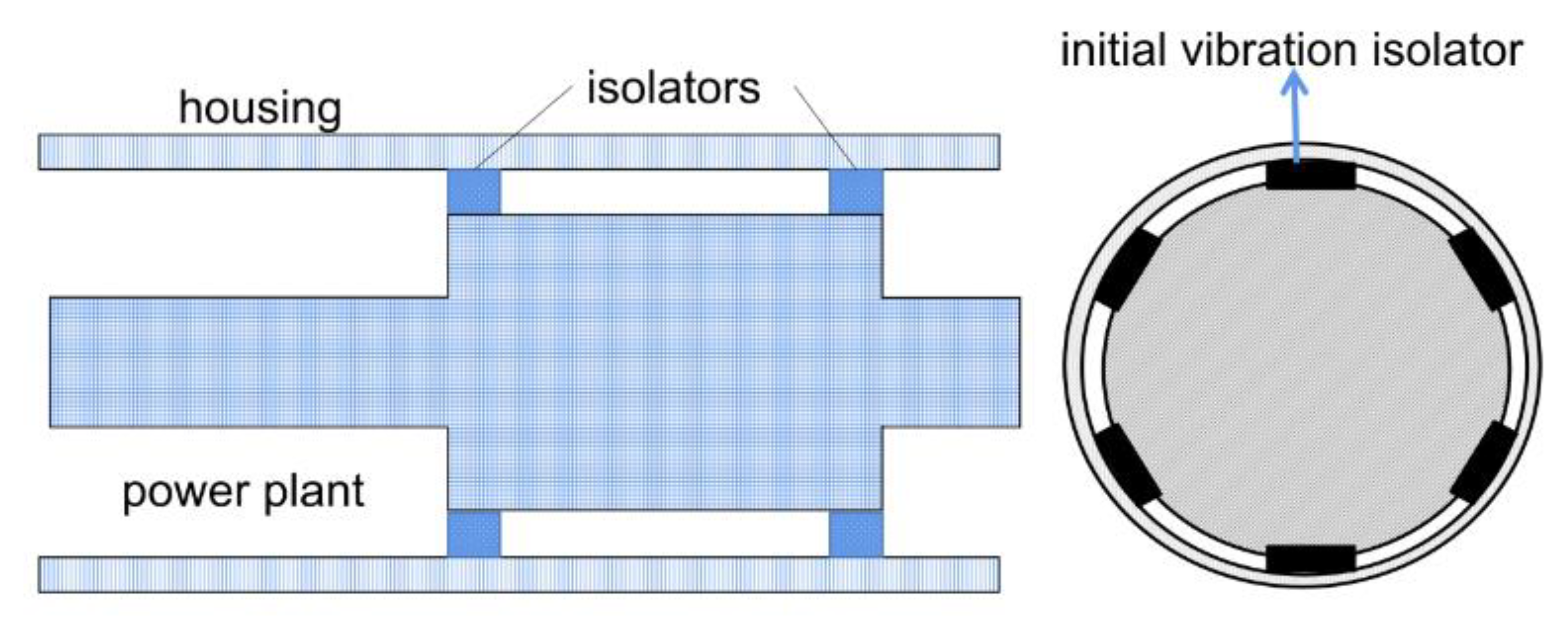
The power plant vibration isolator system consists of a load, vibration isolators and the outer housing, which is schematically shown in
Figure 1. The housing is a thin-walled cylindrical shell, the material is aluminum and the load is an aluminum solid cylinder structure of which the length is the same as the length of the housing. The initial vibration isolators are divided into two groups: the front composition and the rear composition. Each group is composed of 6 identical metal rubber vibration isolation elements, which are arranged approximately evenly along the circumference, and are shown in
Figure 1.
The insertion loss and vibration energy level drop of the vibration isolation system were tested and a schematic diagram of the test system is shown in
Figure 2. The test device for the vibration isolation effectiveness of the vibration isolator was composed of a load, vibration isolators and an outer housing. The entire device was suspended by an elastic rope to simulate a free–free boundary. The load was a solid cylinder and the housing was an aluminum thin-walled cylindrical shell. Moreover, the length of the load was the same as the length of the housing. The isolators were divided into two annular isolators, located in the front and rear. The structural parameters of the systems are shown in
Table 1.
In the test system, the exciter model was BK4808, the power amplifier was BK2712, the type of acceleration sensor was PCB353B04, the data acquisition system was LMS SCADAS Mobile SCM05 and LMS.Test.Lab software was utilized for excitation control and acceleration test. In the test, the exciter acted as a steady-state excitation source to generate white noise excitation. The impedance head was connected to the exciter through the excitation rod to pick up the acceleration response signal and force signal of the excitation point. The exciter was attached to the beam by a flexible cord and the excitation rod extended on the axial direction of the power plant simulator.
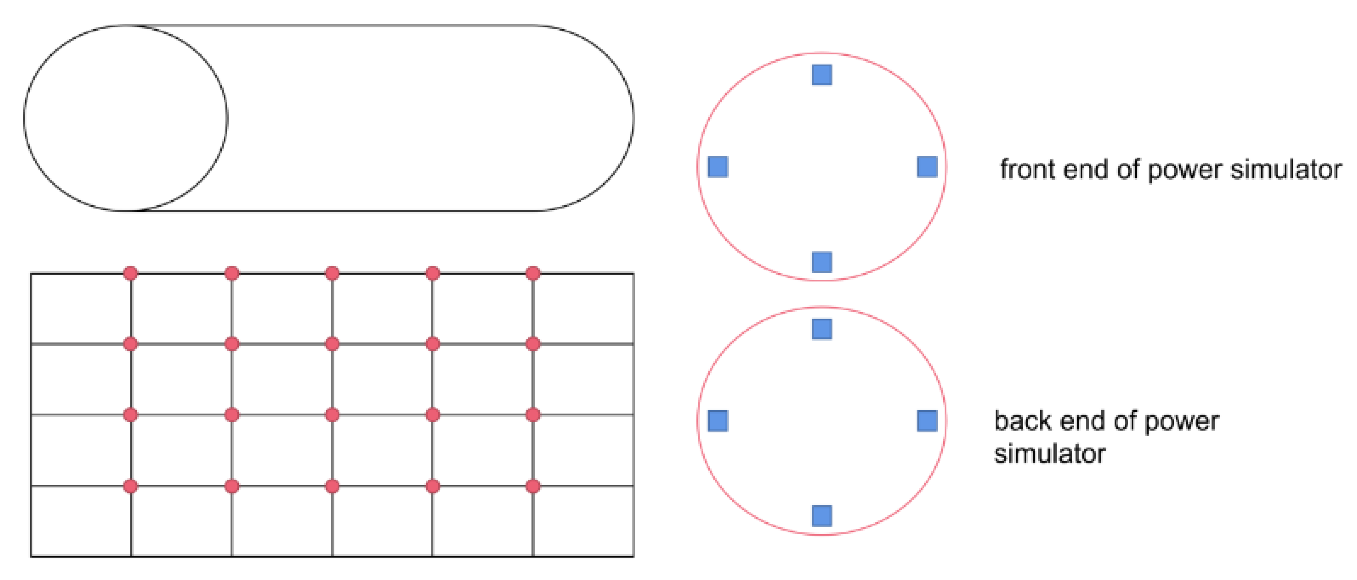
In the test model, a total of 20 radial acceleration sensors were located on the outer surface of the housing, which are shown in
Figure 3. The 20 sensors were divided into 5 groups, which were respectively arranged in the axial position with equal space. In addition, 4 acceleration sensors in the radial direction were installed at the front and rear ends of the power simulator, respectively.
The average acceleration responses of the housing and power plant simulator were determined by:
where
and
was the acceleration value of the
i-th measuring point and the number of acceleration sensors on the housing or power plant simulator.
The vibration energy levels of the housing and power plant simulator were calculated by:
The insertion loss of the vibration isolation system was obtained by the following formula:
where
represented the average vibration levels of the housing before isolation and after isolation, respectively.
The vibration level drop of the vibration isolation system was obtained by the following formula:
where
represented the average vibration levels of the power plant simulator and housing.
The larger and , the lower the response of the housing after isolation, and the more significant the vibration isolation effectiveness of the vibration isolation system was.
The test procedure was:
- (a)
Without installing vibration isolators, a rigid aluminum ring was placed between the load and the housing; thus, the load was directly in contact with the housing through the aluminum ring, the system was excited by the exciter and then, the frequency response of each acceleration measuring point was picked up;
- (b)
Step (a) was repeated and the final acceleration response of each measuring point was obtained by linearly averaging the results of the two repeated measurements, represents the acceleration before isolation;
- (c)
Replacing the aluminum ring of Step (a) with initial vibration isolators, the load and the housing were connected through the vibration isolators, and the shock was excited by the exciter and the data acquisition system picked up the frequency response of each acceleration measuring point;
- (d)
Repeating Step (b), the final acceleration response of each measuring point was obtained by linearly averaging the results of the two repeated measurements and represents the acceleration after isolation;
- (e)
Repeating Step (c) and Step (d) the vibration data of the three new design vibration isolators was obtained.
3. Results of Initial Isolators
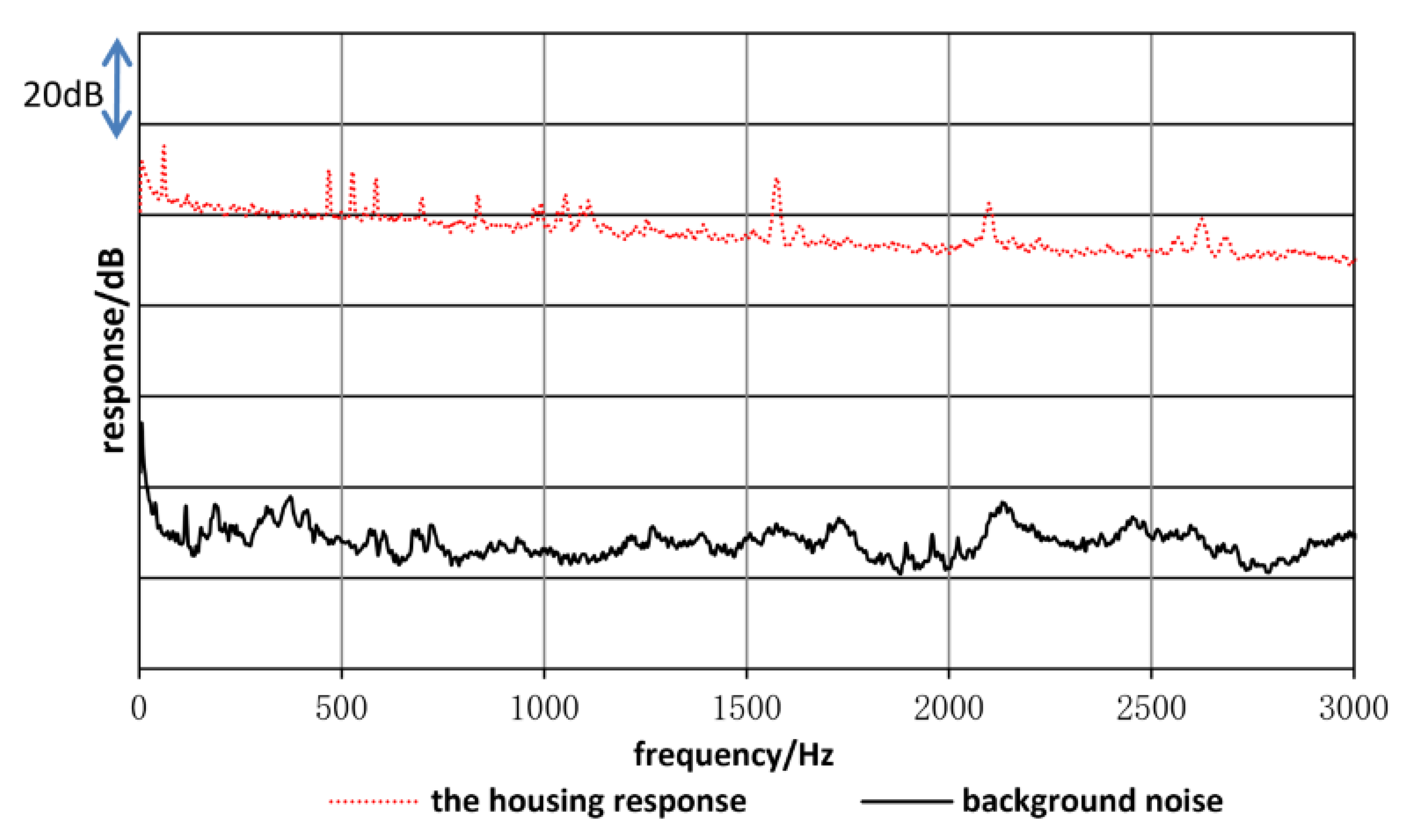
Figure 4 compares the vibration response of the housing with the background noise (the vibration response obtained by the sensors when the vibrator was not working). It can be seen from the figure that, at the peak of the housing’s response, the signal-to-noise ratio reached 70 dB, and outside of the response peak frequency points, the signal-to-noise ratio at other frequencies reached more than 40 dB. This signal-to-noise ratio was sufficient for evaluating the vibration isolation effectiveness of isolators.
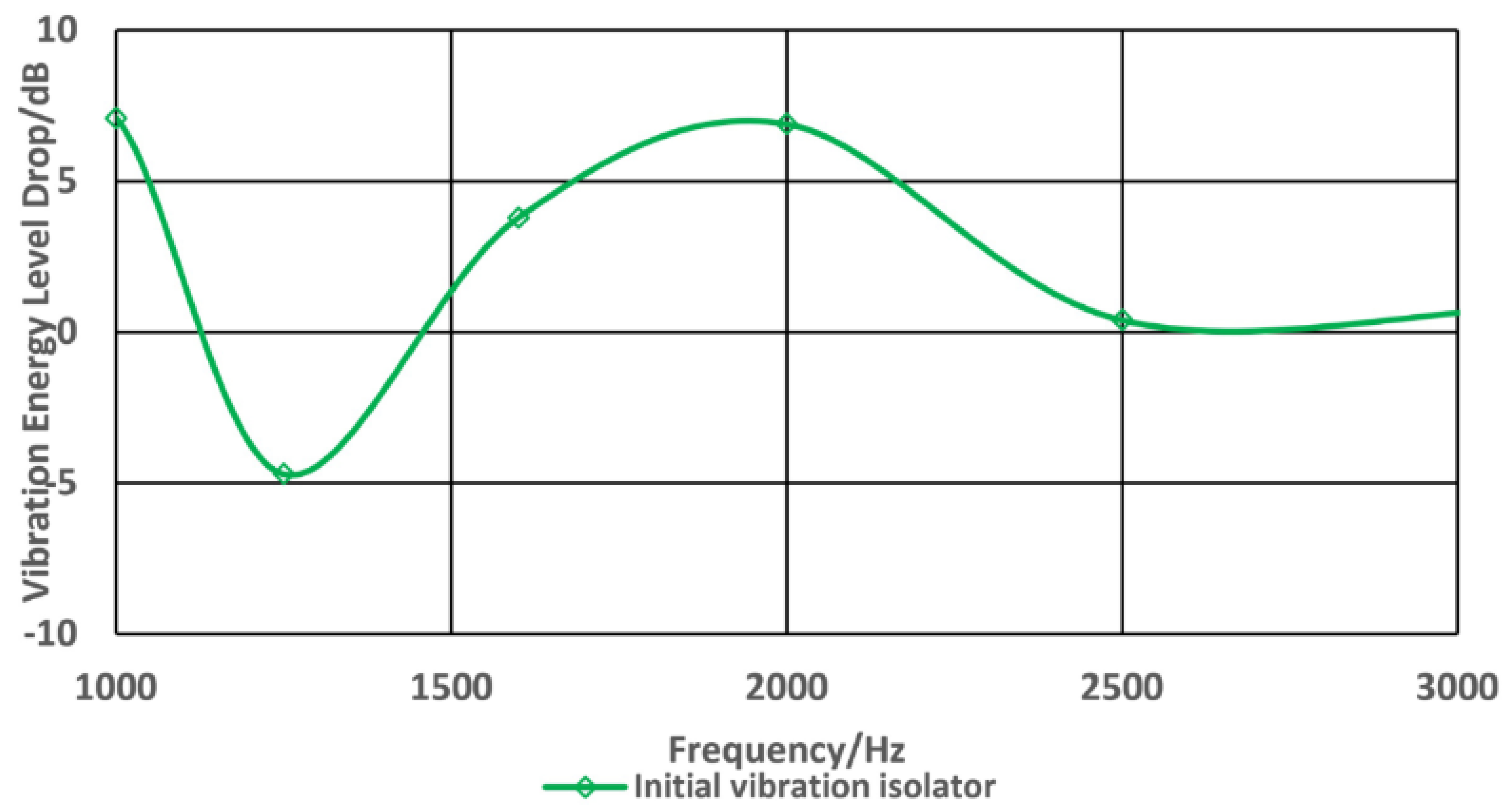
The results of insertion loss and vibration energy level drop of initial isolators are shown in
Figure 5 and
Figure 6, respectively. It can be seen that, in the wide frequency range, the vibration isolation system did not have a good vibration isolation effectiveness, and the insertion loss was always less than 5 dB. As the frequency increased, the vibration isolation effectiveness did not improve, which could not satisfy the vibration isolation requirements.
Analysis and research show that [
1]: the primary reason for the poor vibration isolation effectiveness was that the impedance of the isolator was greater than the housing. In order to improve the vibration isolation effectiveness of the system, this article employed the above analysis results as a guide to design a variety of vibration isolators using different materials, and select vibration isolators that meet the engineering requirements through experimental tests.
4. Improved Isolator Design
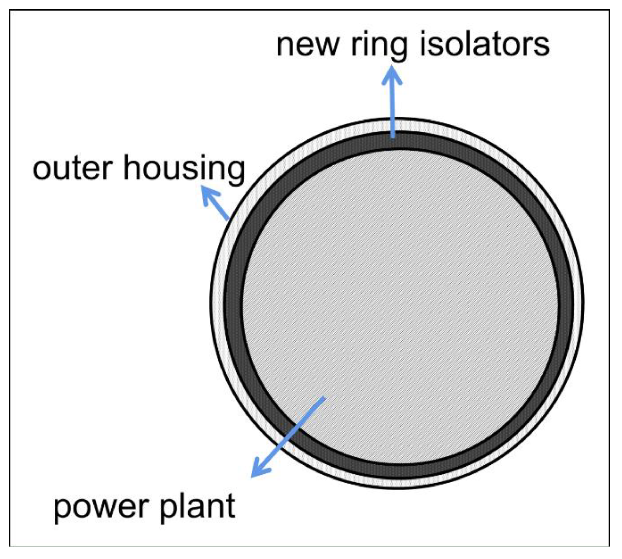
The appearance of the newly designed vibration isolators and their installation in the power plant are shown in
Figure 7. The three newly designed types of vibration isolators are shown in
Figure 8, and their material parameters are shown in
Table 2. They were a ring metal rubber vibration isolator, magnesium alloy vibration isolator and MUHP. Each type of the vibration isolator contained two annular vibration isolators, namely a front vibration isolator and a rear vibration isolator. It should be noted that the overall dimensions of the three new types of vibration isolators were kept the same, and the front vibration isolators and the rear vibration isolators were connected to the dynamic simulation device by screws.
The ring metal rubber vibration isolator included an inner metal ring, an outer metal ring and several arc-shaped metal rubber vibration damping strips. The inner metal ring and the outer metal ring were enclosed to form a cavity, and a plurality of arc-shaped metal rubber vibration damping strips was arranged in the cavity. The arc-shaped metal rubber vibration damping strips were clamped between the inner and outer metal rings in a pre-tightened manner. Both the magnesium alloy isolators and MUHP were integrated vibration isolators, that is, the entire body of the vibration isolator was an independent element.
5. Discussion
The same test method as the initial isolators was employed and the insertion losses of the three types of vibration isolators are shown in
Figure 9. It can be seen from the figure that the ring metal rubber vibration isolators showed a vibration effectiveness of 3–5 dB at an interval of 1–1.5 kHz. However, the insertion loss decreased as the frequency continued to increase. The insertion loss of the magnesium alloy vibration isolators was relatively low, especially in the vicinity of 1 kH; within the range of 1.5–2 kHz, the insertion loss was negative. This also meant that the presence of the magnesium alloy isolators made the vibration response of the housing greater compared to the rigid connection between the power plant and the housing in these frequency bands. MUHP showed a more significant and stable vibration isolation effectiveness in the interest frequency band whose insertion loss was stable at 3–5 dB compared with the other three types of vibration isolators, and there was a trend of continuous improvement as the frequency increased.
From the above comparison, it can be seen that with insertion loss as the evaluation criterion, the vibration isolation effectiveness of MUHP was more significant than that of the initial vibration isolators among the three newly designed vibration isolators. The vibration isolation effectiveness of metal rubber vibration isolators was similar to that of the initial vibration isolators, while the vibration isolation effectiveness of magnesium alloy vibration isolators was insignificant and the phenomenon of vibration amplification appeared.
The vibration level drops for the three types of vibration isolators are shown in
Figure 10. It can be seen from the figure that the vibration level drop of MUHP was greater than 4 dB in the full frequency band, and the maximum value reached 12 dB, which appeared at about 1.6 kHz. The vibration level drop of the ring metal rubber isolators was 0–7 dB, and the maximum value appeared at 1 kHz and 2 kHz. In addition, the maximum value of the vibration level drop of the magnesium alloy vibration isolators also appeared at 2 kHz, but were all less than 10 dB. Observing that the vibration level drop curves of the four types of vibration isolators include the initial isolators, it was found that the vibration level drop showed a downward trend with the increase in frequency after the maximum value of the vibration level drop was reached, which was related to the elasticity of the housing. The outer housing of the underwater vehicle was a typical elastic structure and thus the power plant vibration isolation device was the elastic foundation vibration isolation. As the excitation frequency increased, the modal density of the housing increases and more modes were excited, resulting in the deterioration of the vibration isolation effectiveness of the vibration isolators.
The insertion losses and vibration energy level drop of the four types of vibration isolators were compared in the exciter excitation test. The results showed that the vibration isolation effectiveness of MUHP was more significant than that of the initial vibration isolators and the other two new isolators in the frequency band. To further verify the vibration isolation effectiveness of MUHP in the actual working condition of the power plant, the power vibration test of the vehicle, including MUHP, was carried out and compared with the initial vibration isolators. The result is shown in
Figure 11. It can be clearly seen from the figure that the vibration energy level of the housing surface was mitigated by about 3 dB after installing the MUHP compared to that of the initial isolators.
The vibration isolation effectiveness of the underwater vehicle power plant has been effectively improved through the development of a variety of new vibration isolators. However, the reduction of the vibration energy level of the underwater vehicle housing was very limited. The reason is that in addition to the vibration isolator, the housing is also an important factor affecting the vibration isolation effectiveness of the power plant.
Supposing
M,
k,
c represents the load mass, the stiffness and damping of the isolator, respectively,
k1 is the stiffness of the elastic support system, thus the mechanical impedance of the load, the isolator and the foundation are
,
and
, the impedance of the support system is
, Let
,
, then the insertion loss can be written as [
1]:
It can be clearly seen from the calculation (5) that the insertion loss of the vibration isolation system is mainly related to the impedance ratio of the isolator to the housing and the elastic support and the impedance ratio of the isolator to the load, and is determined by the larger of the two impedance ratios.
The expression of the vibration level drop can be written as:
The magnitude of the vibration energy level drop depends on the quotient of the sum of the impedance of the housing and the supporting boundary with the impedance of the isolator and the load has no effect on it. If the support stiffness is 0, the greater the ratio of the impedance of the housing to the vibration isolator, the greater the vibration level drop and the better the vibration isolation effectiveness. When the mechanical impedance of the load is much larger than that of the sum of the housing and the supporting boundary, the insertion loss is approximately equal to the vibration level drop.
It can be seen from the above comparison and analysis that the other reason for the insignificant vibration isolation effectiveness of the power plant was that the impedance of the isolator was approximately equivalent to the housing. Reducing the mechanical impedance of the vibration isolator is only one of the means to improve the vibration isolation effectiveness. To further alleviate the vibration of the underwater vehicle housing and improve the vibration isolation effectiveness of the vibration isolation device, it is necessary to simultaneously carry out the investigation on the high impedance housing.
6. Conclusions
In this article, the vibration isolation effectiveness of three newly designed vibration isolators, i.e., ring metal rubber isolators, magnesium alloy isolators and MUHP, was evaluated by insertion loss and vibration energy level drop. Our test results showed that the vibration isolation effectiveness of MUHP had a superior vibration isolation performance compared with the original vibration isolators and the other two new vibration isolators. In order to further verify the performance of MUHP in the working condition of the power plant, the power vibration test of the vehicle, when the initial isolators and MUHP were installed, was carried out. The results showed that the vibration response of the outer housing of the vehicle was mitigated by about 3 dB compared with the initial vibration isolators installed. To further alleviate the mechanical vibration of the outer housing, it is essential to carry out investigations on high-impedance housings.


