Article

Nighttime Encounter Situation Recognition for Unmanned Surface Vessels Based on Images of Vessel Navigation Lights


1
Marine Technology and Intelligent Control Research Center, Shanghai Maritime University, Shanghai 201306, China
2
Shanghai Auto Subsea Vehicles Inc., Shanghai 201306, China
*
Author to whom correspondence should be addressed.
J. Mar. Sci. Eng. 2026, 14(8), 761; https://doi.org/10.3390/jmse14080761
Submission received: 16 March 2026 / Revised: 12 April 2026 / Accepted: 18 April 2026 / Published: 21 April 2026
(This article belongs to the Section Ocean Engineering)

Abstract

To address the limitations of existing perception methods for nighttime encounter situation recognition of unmanned surface vessels (USVs), this study proposes an image-based method for navigation-light recognition and encounter situation recognition. In accordance with the International Regulations for Preventing Collisions at Sea (COLREGs), a parameterized 3D geometric model of vessel navigation lights and encounter scenario models is established. Based on the camera imaging principle, a dataset of navigation-light images under various encounter situations is generated through simulation experiments. By analyzing the variation patterns of navigation-light images in different encounter situations, a feature vector composed of area-domain and azimuth-domain features is constructed, and an encounter situation recognition method is developed accordingly. To mitigate the effects of water reflections and interfering light sources in real images, a navigation-light image-processing method is designed for the stable extraction of feature parameters. Simulation results show that the classification accuracy ranges from 96.6% to 98.3% at different distance conditions. In field experiments conducted with a small USV under a three-light configuration, the proposed method achieves a navigation-light recognition accuracy of 96.2% and an encounter situation recognition accuracy of 94.94%. The proposed method provides an interpretable and lightweight complementary visual solution for nighttime encounter situation recognition, complementing existing nighttime perception technologies.

1. Introduction

With the rapid development of unmanned surface vessel (USV) technology, maritime traffic is increasingly shifting toward mixed navigation involving both manned vessels and USVs. All types of vessels are required to comply with the International Regulations for Preventing Collisions at Sea, 1972 (hereinafter referred to as the “COLREGs”) [1]. Whether navigating in maritime or inland waters, vessels must recognize encounter situations and take actions in accordance with the applicable rules [2]. Hence, encounter situation recognition is a prerequisite for vessels to comply with COLREGs. At present, for manned vessels, encounter situations are mainly judged through visual lookout by the crew, with assistance from onboard equipment such as marine radar and the Automatic Identification System (AIS) [3,4]. For USVs, it mainly depends on the fusion of data from onboard perception devices such as AIS, marine radar, and infrared thermal imaging [5].
AIS can transmit vessel navigation data, such as position, heading, and speed, thereby providing key information for shore-based supervision [6]. Jiang Longhui et al. [7,8] calculated the relative motion parameters between vessels from AIS data, screened encounter samples in accordance with the collision-avoidance rules, and reconstructed the complete collision-avoidance process. Murray et al. [9] used a Gaussian mixture model to cluster historical AIS trajectories and predict future vessel tracks. Kim et al. [10] established a hierarchical navigation database based on historical AIS data and integrated vessel type and length information to achieve remote situation-awareness modeling. However, the AIS still has several limitations in practical applications. First, some vessels, such as small fishing boats, are not equipped with AIS devices. Second, even when AIS is installed, problems such as incorrect information entry, falsification, or manual shutdown still occur [11,12]. In addition, the signal is vulnerable to blockage, which creates surveillance blind areas [13]. Meanwhile, the system is readily affected by factors such as network latency, thereby reducing the real-time performance of vessel positioning [14].
Marine radar can provide real-time information of a target vessel, including its position, speed, and heading. Liang Mincang et al. [15] used the target motion parameters and collision parameters, namely the distance at the closest point of approach (DCPA) and the time to the closest point of approach (TCPA), provided by radar ARPA, and mathematically abstracted the principle of manual plotting to realize automatic collision avoidance. Villa et al. [16] conducted a study on path tracking and obstacle avoidance in port environments based on LiDAR and validated the method through field experiments. However, radar also has its limitations. Small targets or vessels employing stealth technology are difficult to detect [17]. In addition, radar cannot provide information such as the colors of navigation lights, which limits its capability to recognize encounter situations [18].
Infrared thermal imaging does not rely on visible light. It passively receives the infrared thermal radiation emitted by a target and converts it into grayscale or pseudo-color images, thereby overcoming the limitations imposed by dim lighting conditions at night [19]. Xu Chengjun et al. [20] used this technology to achieve all-weather image segmentation and coarse localization of berthing ships. However, in high-humidity environments, infrared radiation is easily absorbed and scattered by water vapor, which leads to blurred images and unclear target boundaries [21]. In addition, infrared images are typically grayscale and lack color representation, making it difficult to directly obtain visible-light semantic information such as the colors of navigation lights of vessels [22].
In practical applications, sensing technologies such as AIS, marine radar, and infrared thermal imaging are often integrated into comprehensive onboard perception systems to enhance environmental perception through complementary information. However, such systems still face multiple challenges. On the one hand, different sensors differ in terms of data type, temporal resolution, spatial resolution, and update frequency, and therefore cross-sensor information association and temporal synchronization are required; otherwise, the accuracy of target matching and fusion may be affected [23,24]. On the other hand, multi-sensor systems usually require more hardware devices and more complex data-processing and fusion algorithms, which increases hardware cost, computational burden, and engineering implementation difficulty [5]. In addition, although AIS, marine radar, and infrared thermal imaging can respectively provide vessel identity information, range-and-bearing information, and thermal radiation characteristics, they still cannot directly and accurately represent the semantic information required for nighttime encounter situation recognition, such as navigation-light color, configuration, and display characteristics.
Due to the limitations of the above perception technologies, active visual lookout by the crew still remains the most direct and effective means of encounter situation recognition. Against this background, encounter situation recognition based on visual perception has become an active research topic. Chen et al. [25] used a You Only Look Once (YOLO) model to obtain vessel position information and analyzed its spatio-temporal behavior across consecutive frames. Xu et al. [26] estimated target speed from port surveillance videos by combining an imaging model with a linear regression method, thus achieving target detection and motion assessment. Ding et al. [27] proposed a visible-light video-based method for vessel recognition and collision risk assessment by integrating YOLOv5 with Deep-SORT. Jiang et al. [28] proposed a machine-vision-based method for ship-to-ship collision risk evaluation by integrating an improved YOLOv7 detector with StrongSORT, trajectory estimation, and collision risk index calculation. Liu Shihao et al. [29] achieved vessel encounter situation recognition on a real-world navigation dataset based on deep learning algorithms. Helgesen et al. [30] experimentally validated a daylight camera-based maritime collision avoidance system for autonomous urban passenger ferries. However, their method mainly addressed target tracking and collision-avoidance execution under daytime conditions. These studies mainly focused on vessel type recognition, localization, collision risk assessment, and encounter situation recognition under daytime conditions, and they generally depend on learning-based methods, characterized by high annotation costs, limited generalization ability due to insufficient existing datasets, and high computational demands.
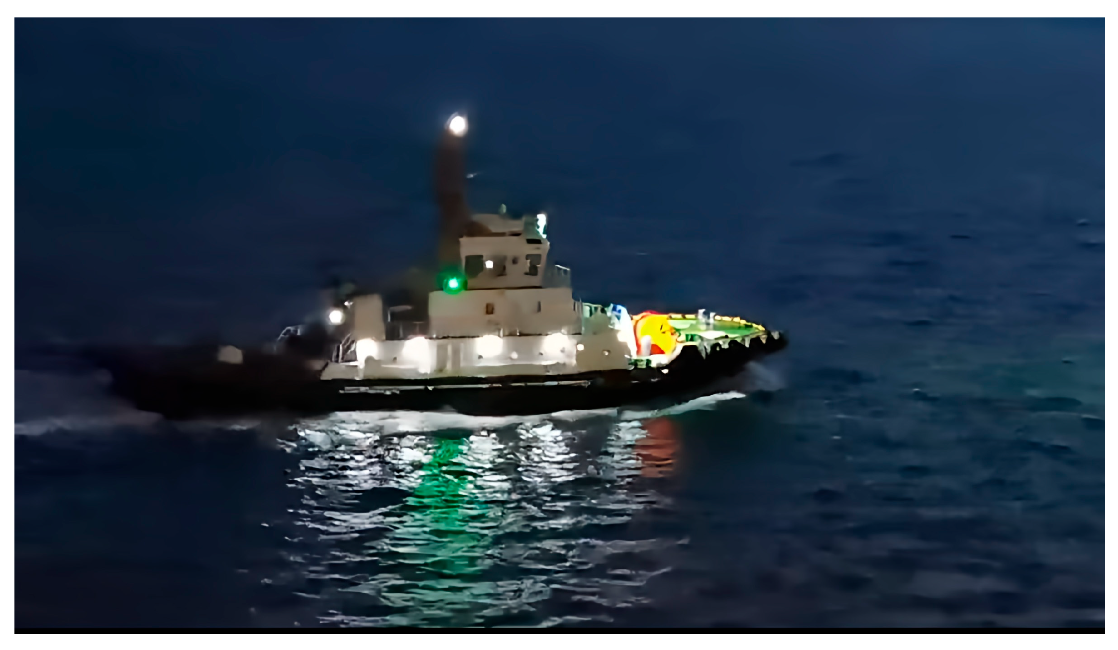
With the growing demand for autonomous nighttime navigation of intelligent ships and USVs, endowing autonomous vessels with a nighttime “lookout” capability analogous to that of human crews has become a key technical direction for improving collision-avoidance performance. As the primary visual signal during night navigation, navigation lights can reflect a vessel’s navigation status through their type, color, and combination, as shown in Figure 1. In response to the problem of visual perception under night navigation conditions, some preliminary studies have been conducted. Nishina et al. [31] found that the accuracy of the YOLOv3 model declined in nighttime vessel recognition and that the HSV thresholding method is more suitable than RGB for extracting navigation-light information and can effectively suppress interference from shore lights; however, no in-depth investigation of subsequent improvements was provided. Liu et al. [32] noted that ships turn on navigation lights during night navigation and used the detected light spots as visual features for nighttime ship detection and tracking. However, their method mainly addressed ship detection and tracking based on navigation-light spots, without further identifying encounter situations. Although Chen et al. [33] achieved hull-contour segmentation for nighttime and other environments through an attention mechanism and the Snake model, their study remained limited to vessel-type recognition. Hu Xin [34] proposed a video-analysis-based method for the navigation-light recognition of maritime vessels, which performed detection, recognition, and tracking of navigation lights in nighttime environments and provided decision-supporting information for intelligent ships to recognize encounter situations; however, the focus is still on the detection and recognition of navigation lights themselves. Bi et al. [35] proposed a method based on vision perception and machine learning for the recognition of anti-collision navigation signals of vessels, in which an improved Adaptive Boosting (AdaBoost) algorithm is used to identify ship types and lights. Although the feasibility of the proposed method is verified in real environments, the classification of light features is not sufficiently explicit to be directly translated for encounter situation recognition. In addition, Gao et al. [36] proposed an improved YOLOv8-based framework for ship-light recognition and the autonomous determination of approaching-vessel types, integrating detection and learning-based classification to infer vessel attributes and constructing a multi-view dataset for vessel-type determination. Qiao et al. [37] proposed a YOLOv8n-based method for ship-light recognition with improved real-time performance. Overall, existing studies have mainly focused on intermediate ship-light recognition, vessel-type determination, or the provision of auxiliary information for navigation assessment, rather than direct encounter situation recognition from navigation-light images. Moreover, these methods generally rely on annotated data and are typically developed and validated on self-built datasets, while publicly available nighttime maritime datasets for navigation-light-based tasks remain limited. Therefore, research on interpretable encounter situation recognition directly from navigation-light images is still lacking.
Taken together, the above studies indicate that nighttime vessel encounter situation recognition still faces three main challenges. First, existing multi-sensor methods cannot directly represent the navigation-light semantic information required for nighttime encounter judgment in accordance with the COLREGs, and they also involve practical challenges in sensor configuration and multi-source fusion [5,6,7,8,9,10,11,12,13,14,15,16,17,18,19,20,21,22,23,24]. Second, although vision-based methods have achieved encounter situation recognition under daytime conditions, their judgments mainly rely on visual cues such as hull appearance, background scene, and motion trajectory, which are significantly reduced in nighttime environments [25,26,27,28,29,30]. Third, existing nighttime studies have mostly focused on intermediate tasks, such as navigation-light recognition and vessel-type recognition, and are further constrained by the scarcity of publicly available nighttime maritime datasets [31,32,33,34,35,36,37]. In this context, direct encounter situation recognition from nighttime navigation-light images remains insufficiently studied.
Therefore, this study proposes a method for direct nighttime encounter situation recognition based on images of vessel navigation lights. The main contributions of this paper are summarized as follows:
  • A direct nighttime encounter situation recognition framework based on vessel navigation-light images is proposed. The framework enables encounter situation recognition directly from single-frame navigation-light images without relying on AIS, radar, or temporal trajectory information.
  • A parameterized geometric model of vessel navigation lights and a corresponding imaging model are established. On this basis, an encounter situation feature vector composed of area-domain and azimuth-domain features is constructed, and interpretable decision rules are developed to realize an explicit mapping between navigation-light image characteristics and encounter situations.
  • A vessel navigation-light recognition method is designed to address the instability of feature extraction in real nighttime scenes under water-surface reflections and interfering light sources. The method combines conventional image-processing operations in a problem-oriented and computationally efficient manner.
  • Simulation and field experiments are conducted for validation. The experimental results indicate that the proposed method shows good effectiveness and feasibility in the tested practical water-surface scenarios.

2. Configuration of Vessel Navigation Lights and Encounter Situations

As the theoretical foundation of this study, the configuration requirements for vessel navigation lights and the criteria for recognizing different encounter situations specified in the COLREGs are first briefly introduced. The full text of COLREGs is available online [38].

2.1. Configuration of Vessel Navigation Lights

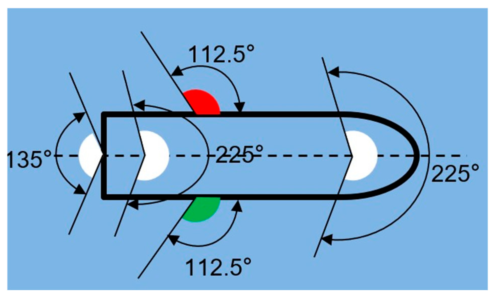
According to the COLREGs, vessel navigation lights generally include masthead lights, sidelights, stern lights, and other lights. A masthead light is a white light installed above the fore-and-aft centerline of a vessel. It may be configured as a fore masthead light and an aft masthead light. Its beam covers an arc of the horizon of 225°, extending from right ahead to 22.5° abaft the beam on either side. Sidelights consist of a red light on the port side and a green light on the starboard side. Each light covers an arc of the horizon of 112.5°, extending from right ahead to 22.5° abaft the beam on its respective side. A stern light is a white light placed near the stern, with a beam covering an arc of the horizon of 135°, extending from right astern to 67.5° from right astern on each side. An all-round light is visible continuously over an arc of the horizon of 360°.
According to the COLREGs, a power-driven vessel of 50 m or more in length, when underway, shall display a fore masthead light, an aft masthead light, port and starboard sidelights, and a stern light. This arrangement is referred to as the five-light configuration. The installation positions and horizontal arcs of visibility of these lights are shown in Figure 2. For small power-driven vessels, the COLREGs permit a simplified navigation-light configuration. A power-driven vessel of less than 12 m in length may use a single all-round white light in lieu of separate masthead and stern lights, which is referred to as the three-light configuration.
According to COLREGs, in addition to the conventional navigation lights of power-driven vessels discussed in this study, other types of navigation lights, special lighting configurations, and display rules applicable to special vessel types and operating conditions are also prescribed. For example, towing lights and flashing lights may be involved in certain cases; a power-driven vessel of less than 7 m in length whose maximum speed does not exceed 7 knots may exhibit only an all-round white light; and special navigation-light rules also apply to ekranoplans, hovercraft, and vessels engaged in towing or pushing operations. Since this study mainly focuses on the recognition of encounter situations for conventional power-driven vessels, the subsequent modeling and analysis are limited to the common navigation-light configurations composed of masthead light, sidelight, stern light, and all-round light.

2.2. Encounter Situations

Based on Rules 13–15 of the COLREGs, encounter situations are classified into three categories: head-on, crossing, and overtaking. The recognition criteria for each category are as follows.
Head-on: A head-on situation exists when one vessel sees another vessel ahead or nearly ahead and, at night, observes the other vessel’s fore and aft masthead lights in line or nearly in line while simultaneously observing both sidelights.
Crossing: When two power-driven vessels are crossing so as to involve a risk of collision, the vessel that has the other on its own starboard side shall keep out of the way of the other. At night, the give-way vessel can observe only the port sidelight of the stand-on vessel, whereas the stand-on vessel can observe only the starboard sidelight of the give-way vessel. Both port-side crossing (i.e., a crossing situation with the target vessel on the port side of the other) and starboard-side crossing (i.e., a crossing situation with the target vessel on the starboard side of the other) are classified as crossing situations.
Overtaking: A vessel is overtaking another vessel when it is coming up with the other vessel from a direction more than 22.5° abaft the latter’s beam. At night, only the stern light of the vessel being overtaken can be seen, while neither sidelight is visible.
As shown in Figure 3, the navigation-light configurations of the target vessel as observed from the own vessel are illustrated separately for the four encounter situations.

3. Visual Modeling of Encounter Situations

Based on the configuration specifications of vessel navigation lights and the recognition criteria for different encounter situations, a parameterized geometric model of navigation lights is first established. On this basis, a navigation-light imaging model is further constructed to represent encounter situation scenarios and simulate the visual characteristics of navigation lights in different encounter situations.

3.1. Navigation-Light Model

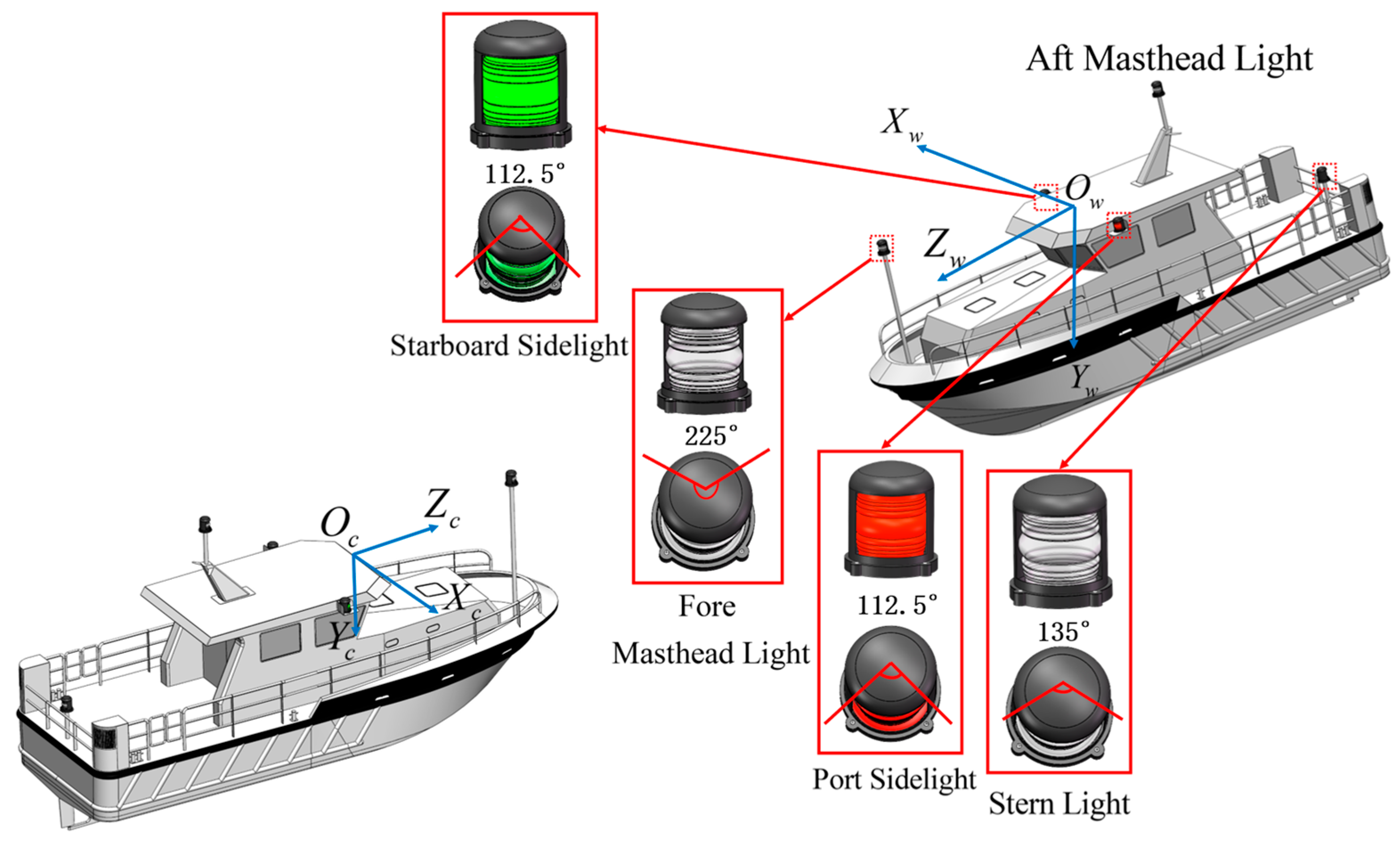
The structure of a navigation light is shown in Figure 4, with a diameter of d = 7.5   cm and a height of h = 11.5   cm . According to the requirements for the positioning of navigation-light specified in Annex I of the COLREGs [38], the target vessel is assumed to have a length of L = 50   m , a beam of W = 20   m , and a height of H = 5   m . As shown in Figure 4, the optical axis of the camera is aligned with the heading direction of the own vessel. Taking the optical center of the camera as the origin, the camera-coordinate system of the own vessel, denoted by O c X c Y c Z c   , is established. The navigation-light coordinate system of the target vessel is denoted by O w X w Y w Z w . In this coordinate system, the port sidelight, starboard sidelight, fore masthead light, aft masthead light, and stern light are arranged, and the coordinates of their installation centers are given as follows:
P center port = W 2 , 3 4 z f , 0 P center star = W 2 , 3 4 z f , 0 P center fore = 0 , z f , L 4 P center aft = 0 , z f + 4.5 , L 4 P center stern = 0 , 3 4 z f , L 2 ,
where z f   denotes the height of the fore masthead light.
To simulate the image projection of navigation lights, a three-dimensional point-cloud set P l o c a l c , i is constructed for each navigation light denoted by c. With the center point of each navigation light taken as the origin of its local coordinate system, the local cylindrical point cloud is generated on the basis of its luminous angular range [ θ m i n ,   θ m a x ] as follows:
P local c = x , y , z | x 2 + y 2 d / 2 2 , z 0 ,   h , arctan 2 y , x θ min ,   θ max
In the navigation-light coordinate system O w X w Y w Z w , the i -th point in the point-cloud set of c is expressed as:
P w c , i = P center c + R c · P local c , i , i = 1 , 2 , , N c ,
where P local c , i P local c , R c is the rotation matrix from the local coordinate system of the navigation light c to the navigation-light coordinate system O w X w Y w Z w , and N c   is the number of points in the navigation-light point cloud.

3.2. Imaging Model of Navigation Lights

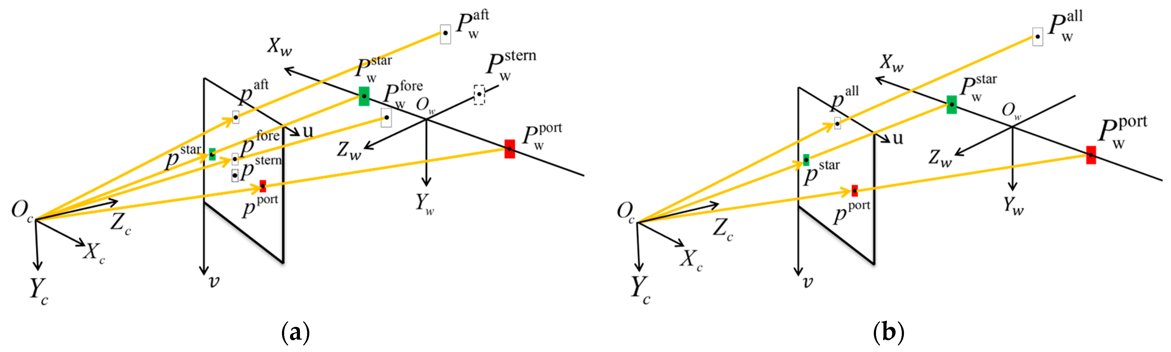
Based on the camera imaging principle, a navigation-light imaging model is established to characterize the projection relationship under different encounter situations. This model is an idealized geometric projection model in which sensor noise, lens distortion, motion blur, and other real-image degradation effects are not considered. As shown in Figure 5a, the five-light configuration is illustrated, whereas Figure 5b shows the three-light configuration. In the five-light configuration, the stern light is visible only in the overtaking situation and is therefore indicated by a dashed box.
The navigation-light coordinates P w c , i = X w c , i Y w c , i Z w c , i T in the navigation-light coordinate system O w X w Y w Z w are transformed into the pixel coordinates p c , i = u c , i v c , i T in the image plane of the camera:
Z cam c , i u c , i v c , i 1 = f x 0 u 0 0 f y v 0 0 0 1 R t X w c , i Y w c , i Z w c , i 1 = M 1 M 2 X w c , i Y w c , i Z w c , i 1 ,
where u 0 , v 0 denotes the pixel coordinates of the principal point of the camera; f x and f y denote the equivalent focal lengths in the row and column directions of the image, respectively; R and t denote the rotation matrix and translation vector, respectively, from the navigation-light coordinate system to the camera-coordinate system; Z c a m c , i denotes the depth coordinate of the i -th navigation-light point in the camera-coordinate system; M 1   is the camera intrinsic matrix, and M 2 is the camera extrinsic matrix.

3.3. Encounter Scenario Model

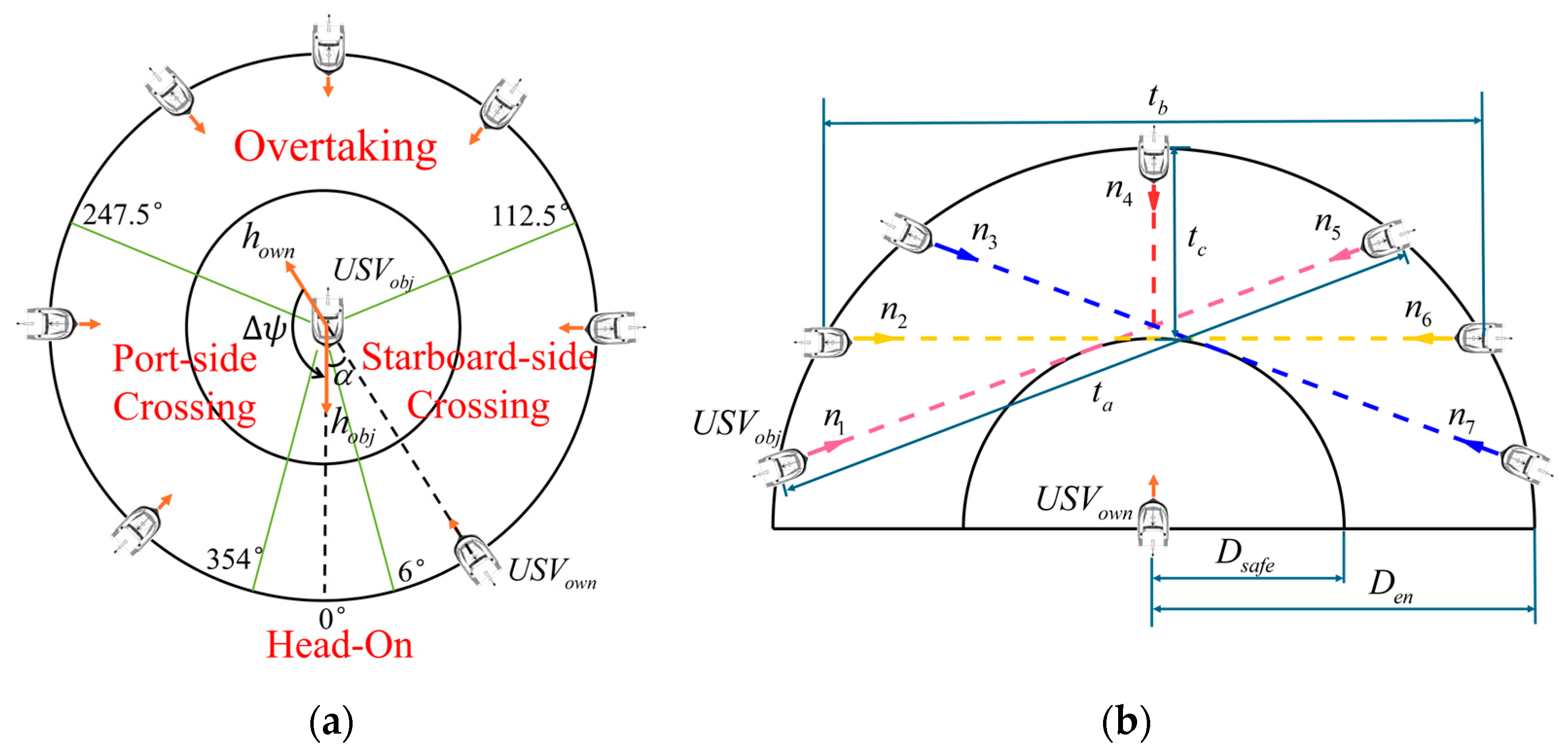
Based on the four typical encounter situations, namely head-on, port-side crossing, starboard-side crossing, and overtaking, the encounter scenarios are modeled as two types of relative motion, as shown in Figure 6, where the own vessel is denoted by USV own , and the target vessel is denoted by USV obj .
In the scenario shown in Figure 6a, the target vessel remains stationary, while the own vessel moves along a circular trajectory centered at the target vessel. The arrows in the figure indicate the viewing directions from the own vessel to the target vessel when the own vessel is located at different positions on the circular path, and α   denotes the dynamic observation angle of the target vessel relative to the own vessel. In addition, h o w n and h o b j represent the heading directions of the own vessel and the target vessel, respectively, and Δ ψ denotes the heading intersection angle, defined as the directed angle from the heading direction of the own vessel to that of the target vessel.
In the scenario shown in Figure 6b, the own vessel remains stationary, while the target vessel moves along a predefined path. The arrow at the position of the own vessel indicates its viewing direction, and the arrows along the path indicate the moving direction of the target vessel. D s a f e   and D e n   denote the safe distance between the two vessels and the distance at which the encounter situation begins, respectively. Each path segment   r j j = 1 ,   2 , , 7 can be expressed as the product of a unit direction vector n j and the corresponding length t j :
r j = t j × n j
where the segment lengths satisfy t 1 = t 3 = t 5 = t 7 = t a , t 2 = t 6 = t b , and t 4 = t c .

4. Vision-Based Encounter Situation Recognition

To achieve vision-based encounter situation recognition, area-domain features and azimuth-domain features of navigation lights are extracted on the basis of the navigation-light imaging model, and a multidimensional feature vector is constructed to characterize the encounter situations. On this basis, an encounter situation recognition method and the corresponding evaluation metrics to quantitatively assess the recognition performance are established.

4.1. Navigation-Light Image Features

First, in the image plane, the luminous region of each navigation light c is extracted, and the corresponding pixel set is denoted by E c :
E c = p c , l = u c , l , v c , l T | l = 1 , , N c pix ,
where   c port   sidelight ,   starboard   sidelight ,   fore   masthead   light ,   aft   masthead   light ,   stern   light ,   all round   light , p c , l   denotes the coordinate of each pixel in E c , and N c p i x   denotes the total number of pixels in this region.
Next, the pixel area A c of each navigation-light region is calculated. The pixel areas of the port sidelight, starboard sidelight, fore masthead light, aft masthead light, stern light, and all-round light are denoted by A port , A star , A fore , A aft , A stern , and A all , respectively.
To reduce variations in absolute area values scale caused by factors such as distance, ambient illumination, and exposure conditions, area ratios and normalized area differences are introduced as area-domain features, and the area-domain feature vector is defined as follows:
X area = x R / M , x G / M , Δ R G , Δ R M , Δ G M , A ˙ stern T R 6 ,
where
x R / M = A port A aft + A fore x G / M = A star A aft + A fore Δ R G = A port A star A port + A star Δ R M = A port A aft A port + A aft Δ G M = A star A aft A star + A aft A ˙ stern = A stern t A stern t 1 Δ t
The vector components are calculated according to Equation (8) only when A aft > 0 . When the aft masthead light is not visible, neither the fore masthead light nor the port/starboard sidelights is visible, namely,   A a f t = A f o r e = A p o r t = A s t a r = 0 , and   x R / M = x G / M = R G = R M = G M = 0 . Moreover, A ˙ s t e r n is calculated only when the stern light is visible.
For the five-light configuration, the area-domain feature vector consists of the pixel areas of the port sidelight, starboard sidelight, fore masthead light, aft masthead light, and stern light. For the three-light configuration, the pixel area of the all-round light replaces that of the fore masthead light and stern light. Accordingly, the vector is composed of the pixel areas of the port sidelight, starboard sidelight, and all-round light.
In addition to the area-domain features, encounter situation recognition also requires the azimuth angle of the target vessel relative to the own vessel; therefore, azimuth-domain features are introduced. In the pixel coordinate system, the azimuth angle θ c   is determined from the ratio of the difference between the horizontal centroid coordinate u c   of the navigation light and the horizontal principal-point coordinate u 0 of the camera to the camera focal length in pixels f x , as follows:
θ c = arctan u c u 0 f x
where the horizontal centroid coordinate of the navigation light c in the image is given by the following:
u c = 1 N c pix l = 1 N c pix u c , l
The azimuth angles of the five navigation lights of the own vessel relative to the target vessel are then combined to form the azimuth-domain feature vector:
X azi = θ aft , Δ port , Δ star , Δ fore , θ stern T R 5
where p o r t = θ a f t θ p o r t , s t a r = θ a f t θ s t a r , f o r e = θ a f t θ f o r e .
For the five-light configuration, the visible navigation lights vary across different encounter situations; the azimuth angles of invisible navigation lights are set to 360° to indicate invalid values. For the three-light configuration, to maintain consistency in the dimensionality of the feature vector with the five-light configuration, the azimuth feature components corresponding to the aft masthead light and the stern light are both assigned the azimuth value of the all-round light.
Finally, the area-domain feature vector and the azimuth-domain feature vector are concatenated to form an eleven-dimensional feature vector:
X = x R / M , x G / M , Δ R G , Δ R M , Δ G M , A ˙ stern , θ aft , Δ port , Δ star , Δ fore , θ stern T R 11

4.2. Analysis of Encounter Situation Features

In the scenario shown in Figure 6a, three typical observation angles are selected for the overtaking situation, namely α { 135 ° ,   180 ° ,   230 ° } , and the navigation-light feature variations are analyzed with the inter-vessel distance D as the variable. For the other encounter situations, the inter-vessel distance is fixed at D safe , and simulations are performed with the observation angle of the own vessel α [ 0 ,   360 ° ] as the variable. By updating the rotation matrix R and translation vector t , the positions and areas of the navigation lights in the pixel coordinate system of the own-vessel camera can be calculated. The simulation is conducted using real camera parameters, with a focal length of 3.6 mm, an image resolution of 1080 × 1920 , and the intrinsic matrix M 1   given by as follows:
1105.4 0 927.7 0 1106.7 526.5 0 0 1
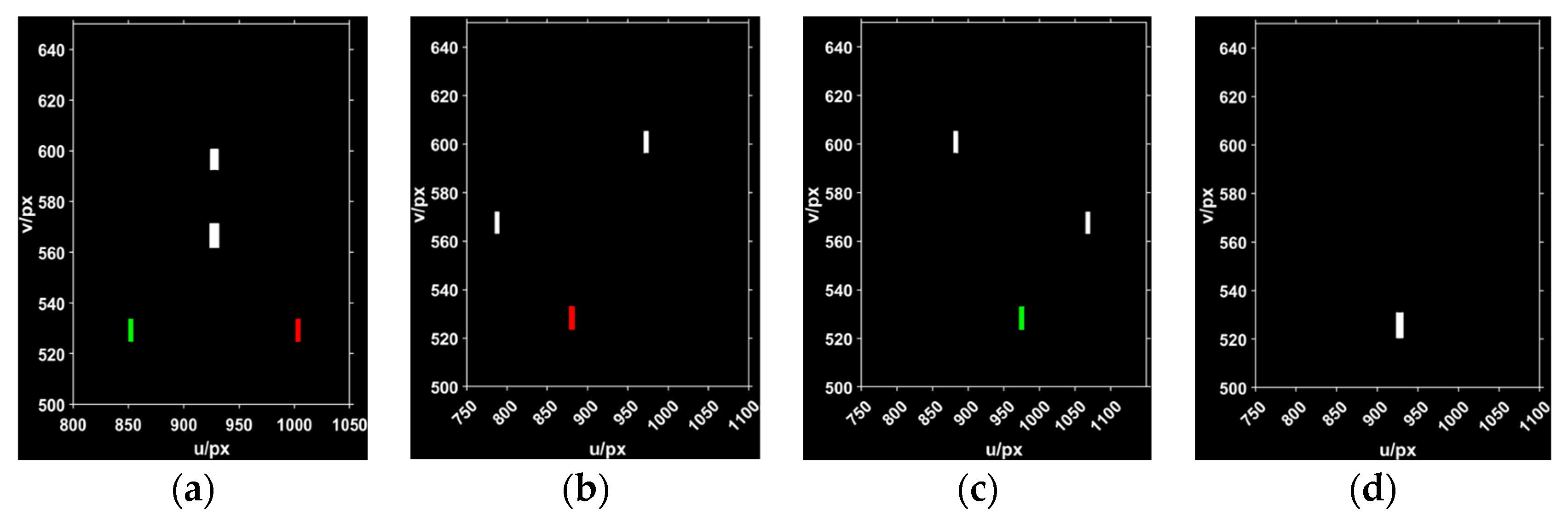
Based on the encounter scenarios shown in Figure 6a and the navigation-light imaging model in Section 2.2, the navigation-light images in the four typical encounter situations can be obtained, as shown in Figure 7.
Based on the above simulation parameters, the area-domain and azimuth-domain feature vectors are calculated for each simulated image frame:
X area v i = x R / M v i , x G / M v i , Δ R G v i , Δ R M v i , Δ G M v i , A ˙ stern v i T X azi v i = θ aft v i , Δ port v i , Δ star v i , Δ fore v i , θ stern v i T ,
where v i denotes the simulation variable, representing the distance D i in the overtaking situation, and the observation angle α i in the other encounter situations.
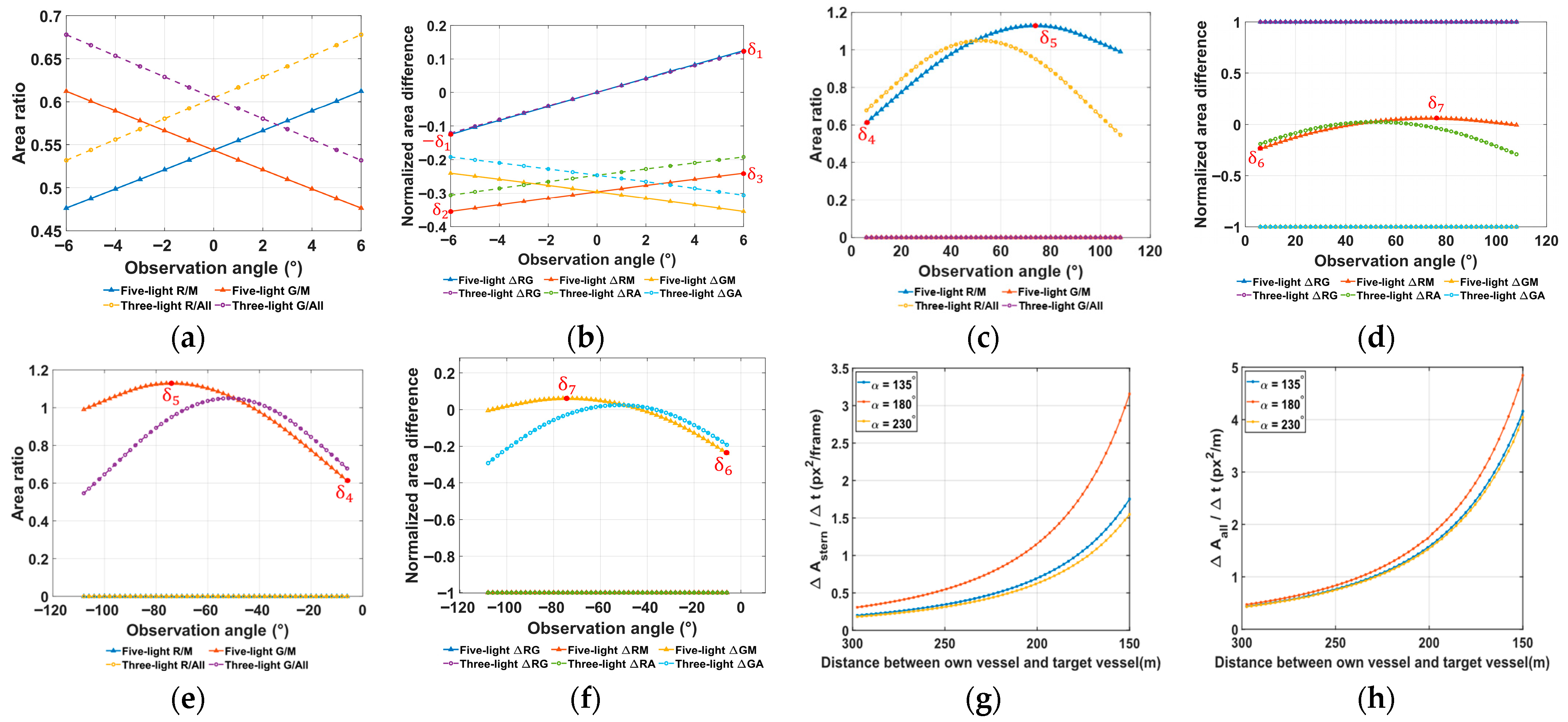
Figure 8 shows the variation patterns of the area-domain feature components in different encounter situations.
It can be seen that, in the head-on situation, the feature vector varies approximately linearly with α , exhibiting an overall bounded monotonic increase or decrease. In the crossing situations, the feature vector exhibits a concave variation curve with extreme points, and the curves corresponding to port-side crossing and starboard-side crossing are approximately mirror-symmetric. In the overtaking situation, the rate of area variation is always positive. In addition, a comparison of the feature components under the five-light and the three-light configurations shows that the two configurations exhibit consistent slope variation trends within the monotonic variation interval.
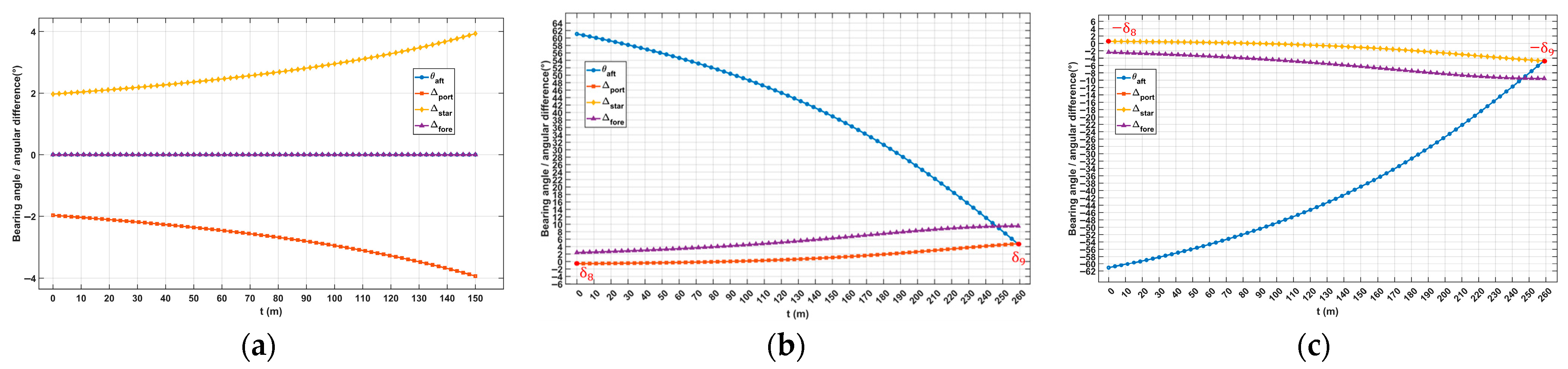
Further simulations are performed based on the encounter scenario paths shown in Figure 6b. Figure 9 presents the variation patterns of the azimuth-domain feature vector in different encounter situations. Due to space limitations, only one representative case from each encounter situation (paths r 2 , r 4 , and r 6 ) is presented. In the overtaking situation, the stern light is located near the center of the image, with its azimuth angle remaining essentially unchanged and only its area varying; therefore, it is omitted from the figure. As can be seen, the azimuth-angle differences between the aft masthead light and the sidelights exhibit distinct characteristics across the various encounter situations, and therefore can be used as the azimuth-domain features for encounter situation recognition.

4.3. Encounter Situation Recognition Based on Visual Feature Vectors

Based on the foregoing analysis of the variation patterns of navigation-light feature vectors in different encounter situations, the encounter situation recognition method is formulated as follows:
Head   on : Δ R G < δ 1 δ 2 < Δ R M < δ 3 Port-side   crossing :   δ 4 < x R / M < δ 5 Δ R G = 1 δ 6 < Δ R M < δ 7     δ 8 < Δ port < δ 9 Starboard-side   crossing :   δ 4 < x G / M < δ 5 Δ R G = 1 δ 6 < Δ G M < δ 7     δ 9 < Δ star < δ 8 Overtaking : A ˙ stern > 0
where δ i i = 1 ,   2 , , 9 are threshold parameters corresponding to specific feature components, as shown in Figure 8 and Figure 9.
For the feature components that vary monotonically, the corresponding thresholds, namely δ 1 δ 3 , are determined by the feature values at endpoints α 0 and α N 1 , with upper and lower bounds determined according to the direction of monotonic variation.
For the feature components whose curves exhibit local maxima or minima, the corresponding thresholds δ 4 δ 9 are determined from the extrema. The first-order derivative is approximated by the forward-difference method:
g i α k = f i α k + 1 f i α k α k + 1 α k , i = 4 , , 9 , k = 0 , 1 , , N 2
where f i ( α k ) denotes the i -th feature value at the observation angle α k .
If g i α k 1 g i α k < 0 , the extremum is considered to lie in the interval [ α k 1 ,   α k ] and its location is estimated by linear interpolation:
α i * = α k 1 g i α k 1 g i α k g i α k 1 α k α k 1 , k = 1 , , N 2
The corresponding feature value at the estimated extremum is then taken as the threshold:
δ i = f i α k 1 + g i α k 1 α i α k 1 , i = 4 , , 9

4.4. Evaluation Metrics

To quantitatively evaluate the performance of the above encounter situation recognition method, Classification Accuracy (Acc), and Recall and Precision for each class are adopted as the evaluation metrics.
Assume that, at a target-vessel distance of D , N D frames of navigation-light images are generated in the simulation, where D denotes the relative distance between the target vessel and the own vessel. Let L k denote the predicted class label of the k -th frame, and the ground-truth label be denoted by L k * :
L k head-on , port-side   crossing , starboard-side   crossing , overtaking
Then, the classification accuracy is defined as follows:
Acc D = 1 N D k = 1 N D 1 L k = L k * ,
where 1 { · }   denotes the indicator function, which takes the value 1 when L k is consistent with the ground-truth label, and 0 otherwise.
In addition to the classification accuracy, a confusion matrix is introduced to describe the class-wise distribution of the recognition results. Let C = [ c i j ] denote the confusion matrix, where c i j is the number of image frames whose ground-truth label is class j and the predicted label is class i . If an image frame does not satisfy any of the predefined decision rules, it is labeled as “Unknown” and regarded as incorrectly recognized when calculating Acc, as well as the class-wise Recall and Precision, for the four encounter situations.
Based on the confusion matrix, the recall of the class i is defined as follows:
Recall i = c i i Σ m c m i ,
which represents the proportion of correctly recognized image frames among all image frames whose ground-truth label belongs to class i .
The precision of class i is defined as:
Precision i = c i i Σ n c i n ,
which represents the proportion of correctly recognized samples among all image frames predicted as class i .
Table 1 summarizes the classification accuracies of simulations performed with the target vessel at distances of D { 200 m ,   250 m ,   300 m } . It shows that, as the distance decreases, the accuracy increases and reaches 98.3% at 200 m. The simulation errors mainly occur near the decision boundaries. According to the COLREGs, “when a vessel is in any doubt as to whether such a situation exists, she shall assume that it does exist and act accordingly.” Therefore, the recognition results for such boundary scenarios are still reasonable in practical navigation. It should be noted that the above results are obtained under idealized simulation conditions of the navigation-light imaging model described in Section 3.2. Hence the effectiveness of the proposed method for encounter situation recognition is verified under these idealized simulation conditions. The influence of practical factors in real images is further addressed in Section 5 through navigation-light image processing.
Table 2 shows the overall confusion matrix obtained from all simulated samples at all tested distances for further evaluation of class-wise recognition performance.
Based on Table 2, the recall values for port-side crossing, starboard-side crossing, head-on, and overtaking are 96.79%, 96.79%, 87.18%, and 100.00%, respectively, while the corresponding precision values are all 100.00%. According to the corresponding feature parameter values, all the recognition errors are found to belong to image frames near the decision boundaries, rather than being widely confused with other encounter categories. This reflects the boundary uncertainty under strict rule matching in the idealized simulation environment and is consistent with the conservative handling principle of the COLREGs for doubtful encounter situations.

5. Vessel Navigation-Light Image Processing

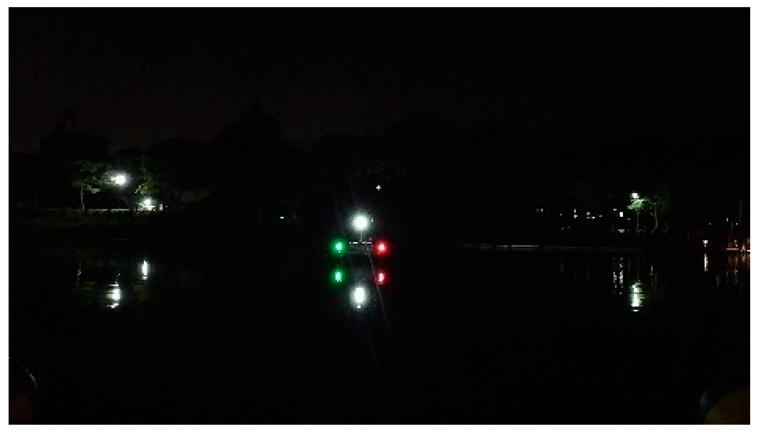
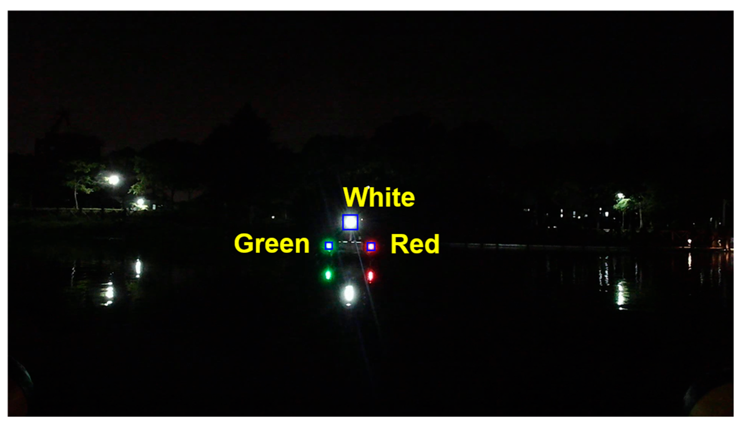
The extraction of encounter situation feature vectors from vessel navigation-light images described above is performed under simulation conditions. In practical applications, the acquired images are easily affected by three main factors: low contrast between navigation lights and the dark background, interference from background light sources, and water-surface reflections, which may produce circular flare spots and vertically elongated reflection streaks, as shown in Figure 10.
This study aims to achieve encounter situation recognition from a single-frame navigation-light image, so that a judgment can still be made when only short-term observation is available or when complete temporal information is not reliably accessible. For this reason, temporal methods such as target tracking, inter-frame association, and trajectory-based filtering are not incorporated into the present framework. Instead, an interpretable and computationally efficient image-processing pipeline is developed according to the characteristics of nighttime maritime images. Gamma correction is used to enhance the contrast between navigation lights and the dark background. Morphological filtering is applied to suppress isolated noise while preserving the basic shapes of light regions. Grayscale-based and color-based segmentation are combined to exploit both intensity and color cues of navigation lights, and candidate-region matching is introduced to improve the reliability of light extraction.

5.1. Gamma Correction

The color image acquired by the camera is denoted as follows:
I c ( u , v ) = [ r ( u , v )   g ( u , v )   b ( u , v ) ]
where u , v represents the pixel coordinates in each image frame. Gamma correction is then applied as follows:
I γ ( u , v ) = 255 · I c ( u , v ) 255 γ
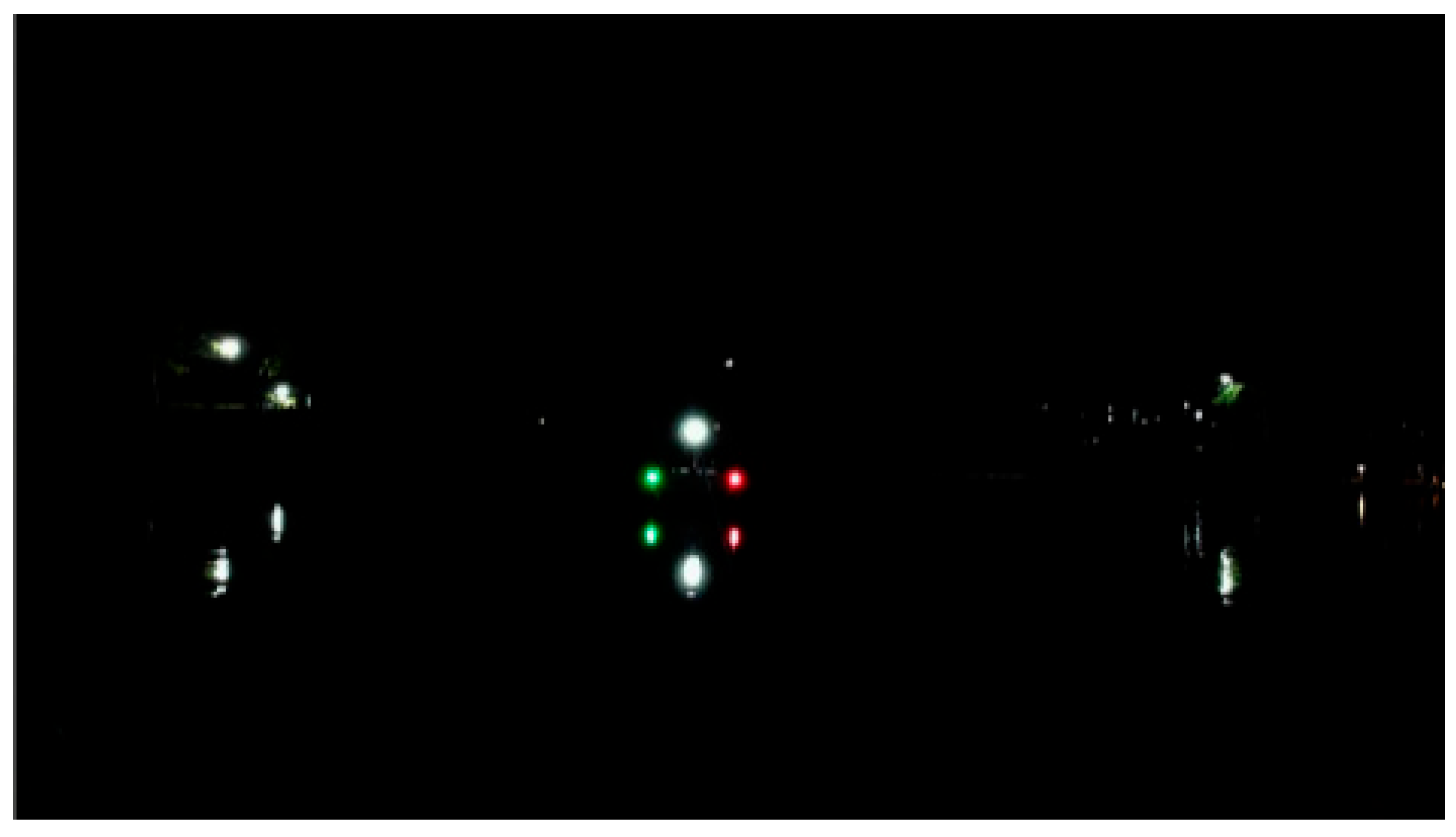
where γ is the gamma coefficient. Figure 11 presents the gamma-corrected image corresponding to Figure 10. It can be seen that the low-gray-level background and water-surface reflection noise are suppressed, while the bright navigation-light regions are relatively enhanced, thereby improving the contrast and distinguishability between the navigation lights and the nighttime background.

5.2. Grayscale-Based Image Segmentation

To further localize the navigation-light regions, the image I γ ( u , v ) is converted into a grayscale image I g r a y ( u , v ) , and the Otsu method is employed to determine the optimal threshold. The between-class variance is defined as follows:
σ B 2 T = p 0 T · p 1 T μ 0 T μ 1 T 2 ,
where p 0 ( T ) and μ 0 ( T ) denote the pixel probability and grayscale mean of the foreground class, respectively, and p 1 ( T ) and μ 1 ( T ) denote the pixel probability and grayscale mean of the background class, respectively.
The optimal threshold T * is given by the following:
T * = arg max T σ B 2 T
According to this threshold, the grayscale image is binarized to obtain the binary image I b i n .
To remove noise, a morphological opening operation is performed on I b i n   using a rectangular structuring element K r with a side length of 3:
I open u , v = I bin u , v K r K r
Next, the connected regions in I o p e n ( u , v ) are extracted. Suppose that there are n connected regions in total, and the i -th connected region is denoted by B i i = 1 ,   2 , , n . Its area, denoted by S i , is defined as the total number of pixels in the region, and its centroid coordinates x i , y i are given by the following:
x i , y i = 1 S i p = 1 S i x p , 1 S i p = 1 S i y p
where p is the pixel-point index in B i p = 1 ,   2 , , S i .
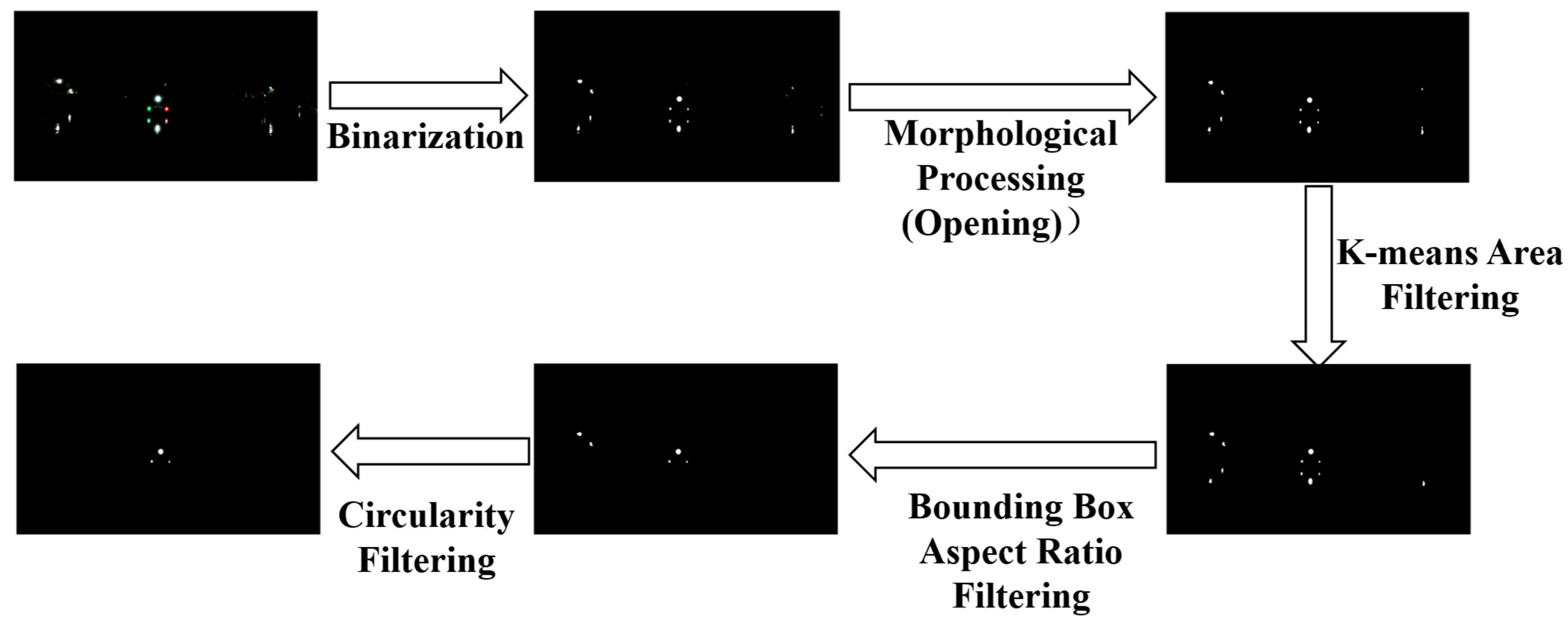
To reduce the influence of small bright spots, the area of each connected region, denoted by S i i = 1 ,   2 , , n , is taken as the feature for K-means clustering and screening. The n connected regions are partitioned into K clusters ( K = 2 in this study), corresponding to the “navigation-light region” and the “small bright-spot interference region”, respectively. The j -th cluster is denoted by C j j = 1 ,   2 . To improve the homogeneity of the area elements within each cluster, the sum of squared errors is minimized, and the objective function is defined as follows:
J = j = 1 K S i C j S i m j 2
where m j is the mean of the data points in the j -th cluster:
m j = 1 C j S i C j S i
where C j denotes the number of area elements contained in cluster C j .
According to the K-means clustering results, the cluster with the largest mean area is selected as the navigation-light region cluster, denoted by C j * , and the upper and lower bounds of the area constraint are determined from the areas within this cluster:
S min < S i < S max ,
where   S m i n = min S i C j * S i and S m a x = max S i C j * S i . The area range of the navigation-light regions is 105 ,   1077 , whereas the area range of small interfering light sources is [ 25 ,   169 ] .
Nighttime recognition of vessel navigation lights is susceptible to water-surface reflections, including reflected streaks and irregular light-source interference. To address this issue, additional geometric constraints are introduced, requiring the aspect ratio of the bounding rectangle and the circularity of each connected region to satisfy:
λ 1 < L i W i < λ 2 C 1 4 π S i P i 2 C 2
where λ 1 = 0.6 , λ 2 = 1.5 , L i   and W i denote the length and width of the bounding rectangle of the i -th connected region, respectively; C 1 = 0.5 , C 2 = 1.0 and P i denotes the perimeter of the i -th connected region.
Based on the above constraints, the candidate region set based on grayscale features is obtained as R B = R i B B i B = 1 N B , in which the positional information of each connected region is retained. Figure 12 shows the image-segmentation procedure based on grayscale features.

5.3. Color-Based Image Segmentation

Threshold-based segmentation of navigation-light images in the HSV color space is more intuitive and better aligned with visual characteristics than segmentation in the RGB color space, while also requiring less computation. Therefore, the image I γ ( u , v ) is transformed into the HSV color space to obtain I h s v ( u , v ) .
Based on the collected images of vessel navigation lights, the histogram distributions of the three colors of navigation-light colors in the ranges of HSV space are analyzed to determine the ranges of HSV thresholds of the navigation lights, and the navigation-light images are then binarized accordingly:
I mask _ red = 1 ,   ( 0 ° H 10 ° 150 ° H 180 ° )         43 S 255 110 V 255 0 ,   otherwise
I mask _ green = 1 ,   40 ° H 100 ° 43 S 230         60 V 155 0 ,   otherwise
I mask _ white = 1 ,   0 ° H 180 ° 0 S 51         136 V 255 0 ,   otherwise
I mask ( u , v ) = I mask _ red I mask _ green I mask _ white
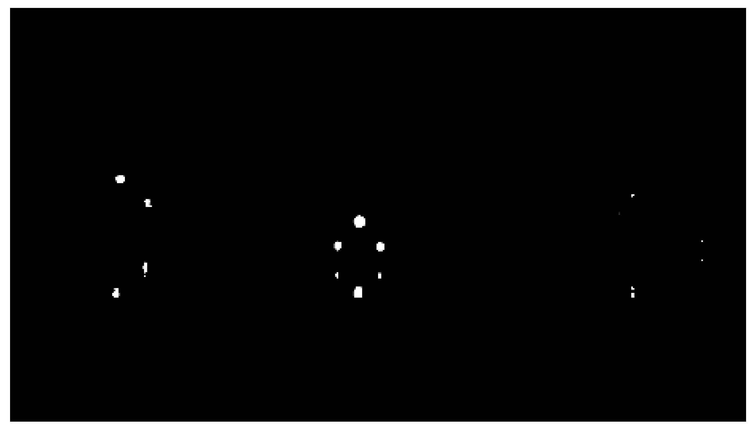
Figure 13 shows the image-segmentation results based on color features, from which the color-based candidate region set R C = R i C C i C = 1 N C is obtained.

5.4. Candidate Region Matching

To reduce false detections caused by segmentation errors arising from a single feature, the candidate regions R B and R C obtained above are fused, and matching is performed at the region level by introducing the intersection over union (IoU). Each grayscale candidate region R i B B and color candidate region R j C C is regarded as a two-dimensional mask composed of a pixel set. For any pair R i B B R j C C , the IoU is defined as follows:
IoU i B , j C = R i B B R j C C R i B B R j C C
where · denotes the number of pixels in the pixel set. A larger IoU value indicates a greater spatial overlap between the two regions and therefore a higher likelihood that they correspond to the same navigation light. Given a threshold δ , when I o U ( i B ,   j C ) δ , R i B B   and R j C C are regarded as successfully matched, and the matched region is denoted as follows:
R match = R i B B , R j C C | IoU i B , j C δ
The matching result is shown in Figure 14. As can be seen, in the head-on situation under the three-light configuration, the port sidelight (red), starboard sidelight (green), and all-round light (white) are successfully recognized.
Based on the matching result, the feature vector is obtained as follows:
X = 0.485 , 0.587 , 0.087 , 0.347 , 0.268 , 0.79 ° , 2.8 ° , 2.93 ° , 0 ° , 360 ° T

5.5. Evaluation Metric for Navigation-Light Recognition

To quantitatively evaluate the performance of the proposed method in field conditions, the navigation-light recognition rate is defined at the image level as follows:
R i m g = N correct _ img N i m g × 100 % ,
where N i m g denotes the total number of evaluated images, and N c o r r e c t _ i m g denotes the number of images in which all visible navigation lights are correctly recognized. An image is regarded as correctly recognized when the categories and numbers of all visible navigation lights are correctly identified, without additional false detections.
It should be noted that the accuracy of navigation-light image recognition is adopted as the only evaluation metric in this section. This is because the purpose of this part is not to independently evaluate the detection performance of individual navigation-light targets or the accuracy of pixel-area measurement, but to assess whether the recognition result of a navigation-light image can provide valid input for the subsequent encounter situation recognition. In addition, since the true pixel areas of visible navigation-light regions in field images are unavailable as ground truth, rigorous quantitative error evaluation of the extracted area parameters is difficult. Therefore, the accuracy of navigation-light image recognition is more suitable for this section.

6. Field Experiments

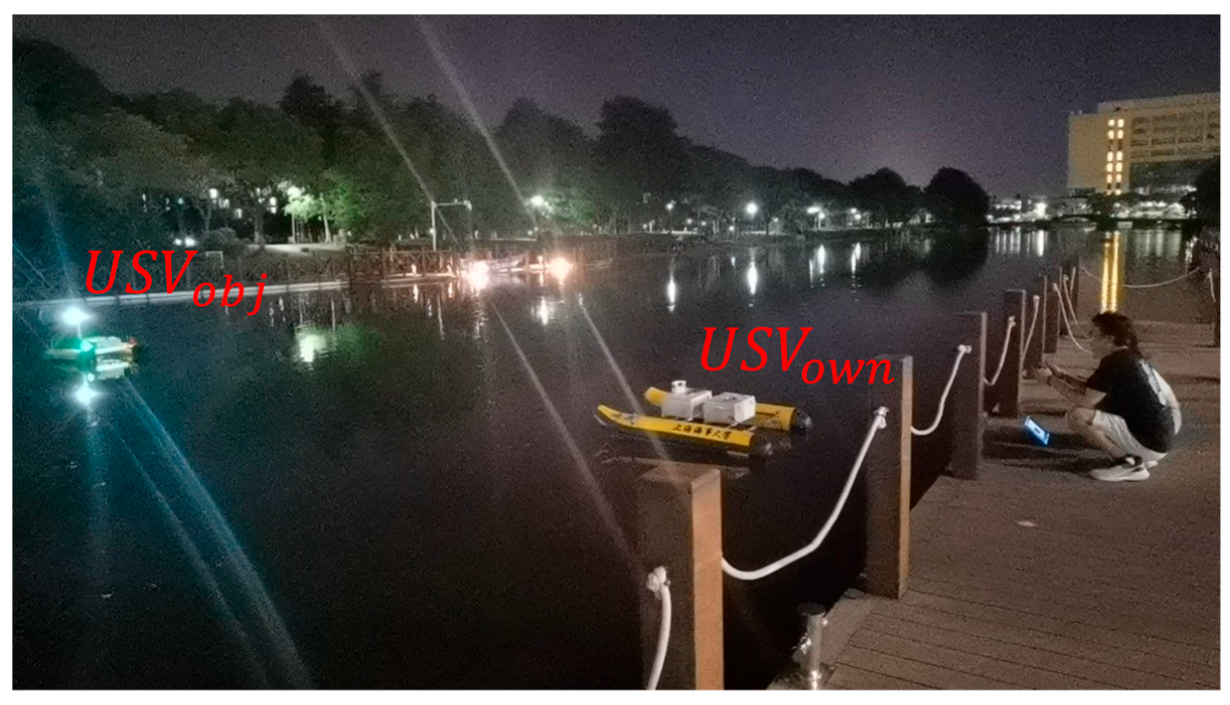
To verify the feasibility of the proposed method in real-world scenarios, a field experiment is conducted on a lake, as shown in Figure 15. The USV carrying the navigation lights to simulate the target vessel is denoted by USV obj , whereas the other USV equipped with a camera is denoted by USV own .

6.1. Hardware Configuration

Both USVs are equipped with GNSS and an electronic compass to measure their positions and headings, respectively. In the present experiments, the GNSS provides approximately 1 m positioning accuracy, while the electronic compass provides a heading accuracy of approximately 1°. An industrial camera is mounted on USV own for real-time image acquisition. The camera has a resolution of 1920 × 1080 and a focal length of 3.6 mm. The intrinsic parameters corresponding to the matrix M 1 in Section 3.2 has been obtained with camera calibration.
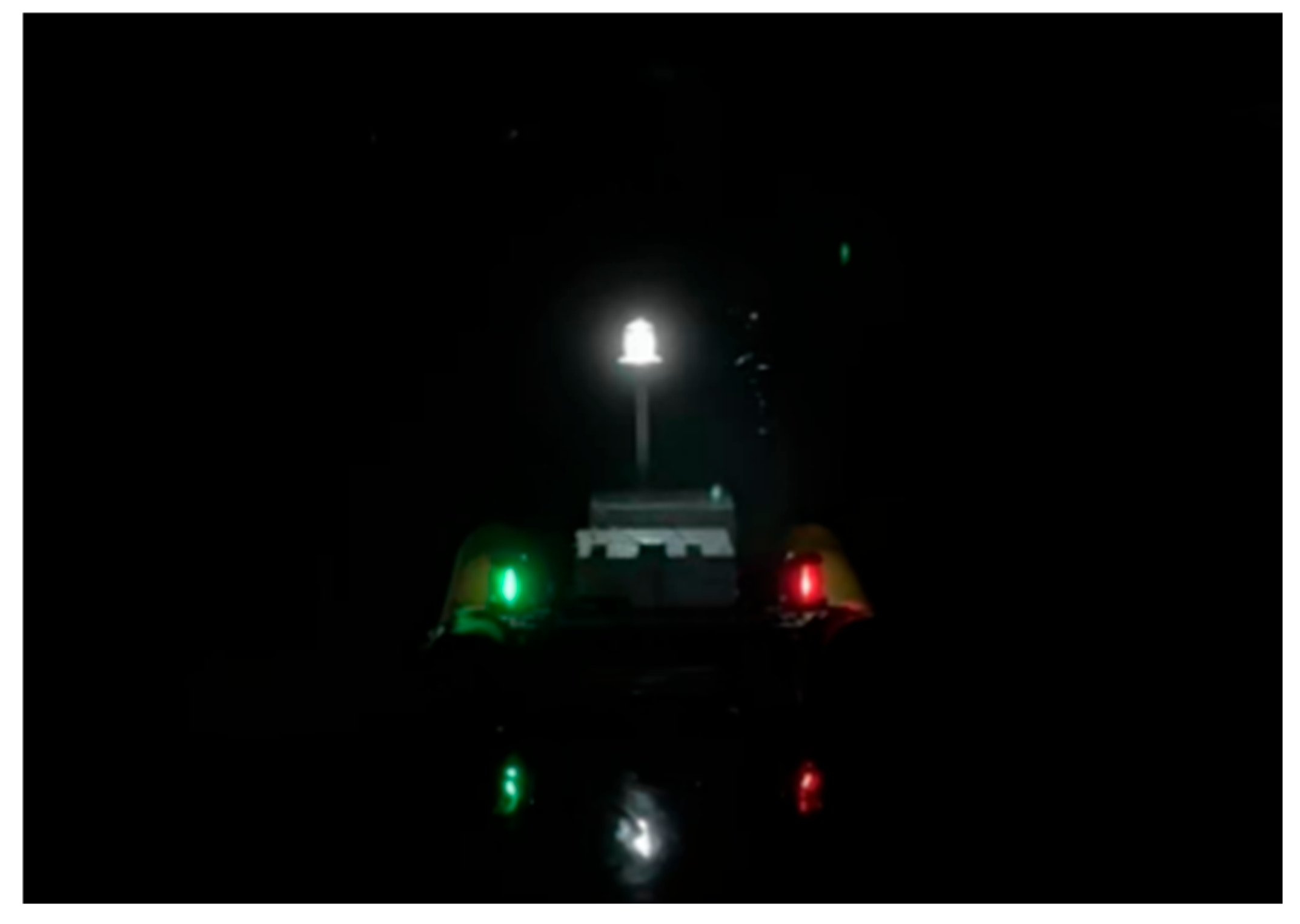
The overall length of USV obj is 1.6 m, and its beam is 1.2 m. In accordance with the COLREGs, port and starboard navigation lights are installed on the sides of the hull, and a white 360° all-round light is mounted on the centerline at the stern. All three lights use LED navigation lights, and their luminous angles, luminous intensities, and dimensions all comply with the relevant specifications. Figure 16 shows USV obj and the experimental setup of its navigation lights.

6.2. Experimental Method

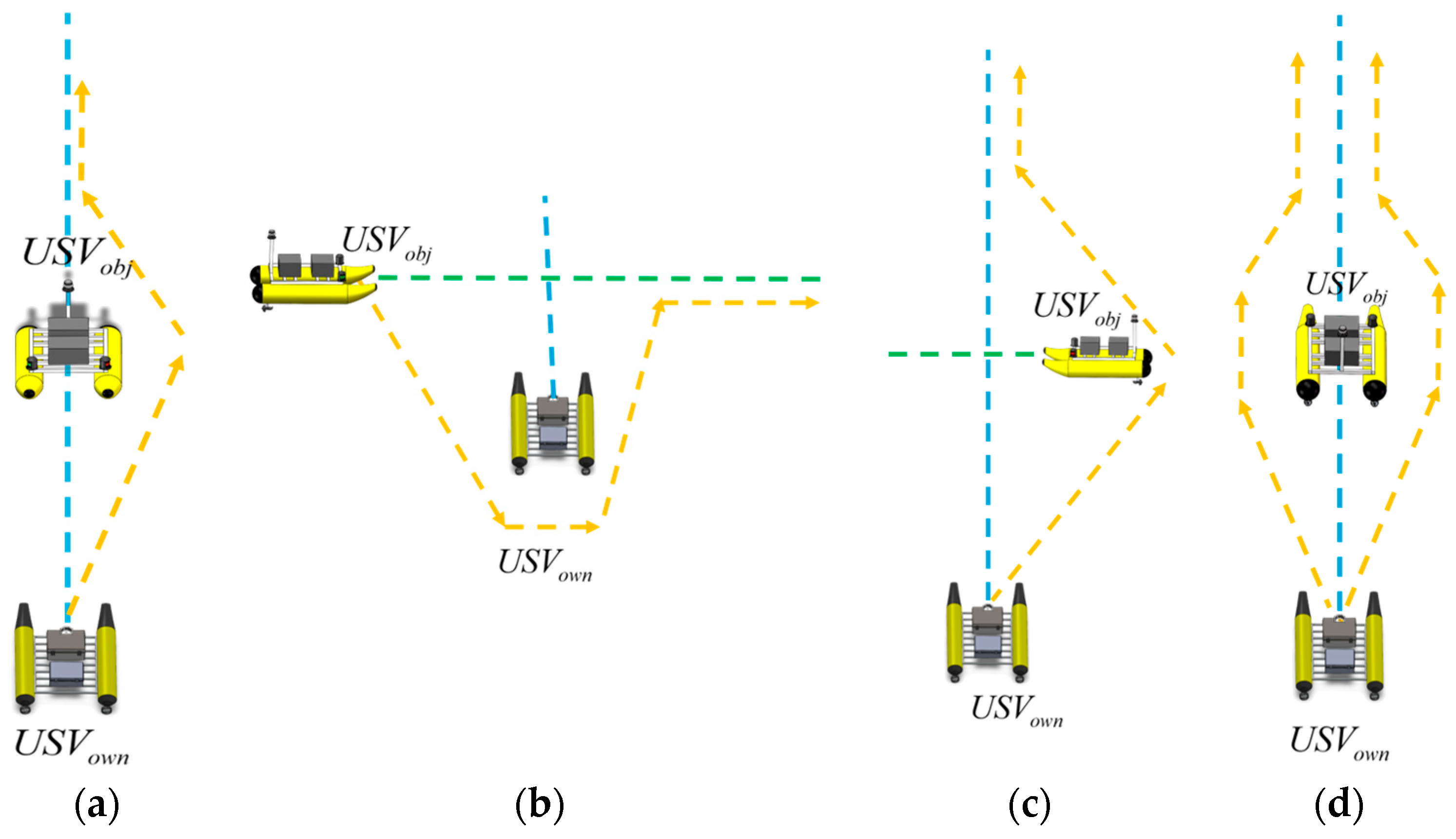
USV obj is in motion and is manually maneuvered on the lake to simulate the navigation process of the target vessel in the encounter scenarios shown in Figure 6b, while U S V o w n remains stationary to simulate the observation point of the own vessel. As shown in Figure 17, four typical encounter situations are designed, namely head-on, port-side crossing, starboard-side crossing, and overtaking.
To evaluate the performance of the proposed vision-based encounter situation recognition, the heading intersection angle Δ ψ is calculated from the compass data of the two vessels in the experiment. According to the COLREGs, the encounter situations can be classified according to the value of Δ ψ and the resulting labels are taken as the ground truth:
  • Head-on: Δ ψ [ 165 ° ,   195 ° ] ;
  • Overtaking: Δ ψ [ 315 ° ,   360 ° ] [ 0 ° ,   45 ° ] ;
  • Port-crossing: Δ ψ [ 45 ° ,   165 ° ] ;
  • Starboard-crossing: Δ ψ [ 195 ° ,   315 ° ] .

6.3. Experimental Results

6.3.1. Vessel Navigation-Light Recognition

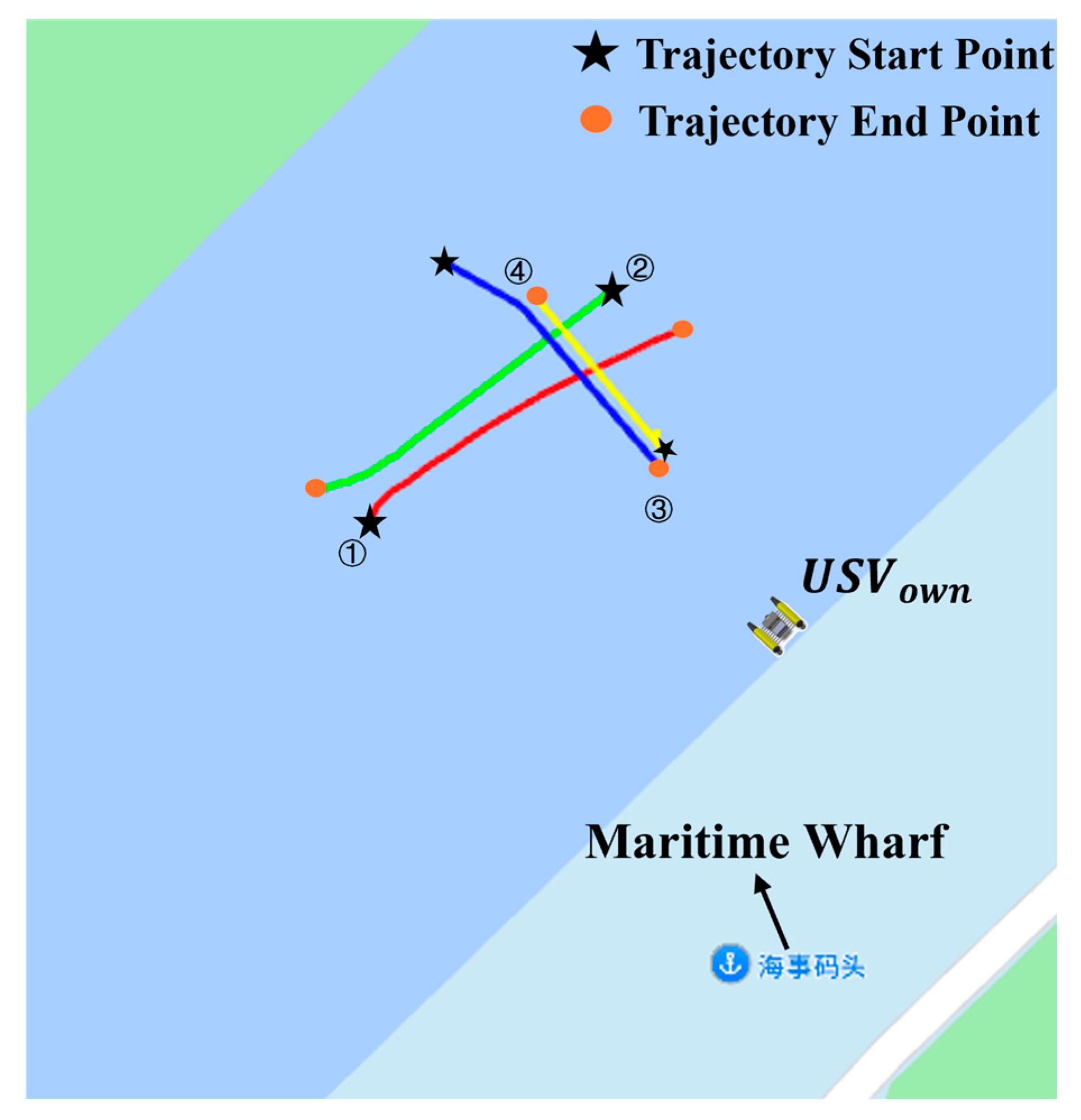
Four actual trajectories of the target vessel U S V o b j , corresponding to four typical encounter situations, are used for analysis, as shown in Figure 18. These trajectories are plotted based on GNSS data. 79 field images are collected along these actual trajectories, consisting of 21, 21, 18, and 19 images for the port-crossing, starboard-crossing, head-on, and overtaking situations, respectively. The sampling rate is 1 frame per second. These images are used both for the validation of navigation-light recognition results and for the subsequent analysis of encounter situation recognition.
The recognition result of each image is compared with the manually annotated ground truth on an image-by-image basis. Among the 79 images, 76 images are correctly recognized, achieving a recognition accuracy of 96.2%. Errors mainly occur when the target is at a relatively long distance. In such cases, the color features of the navigation lights become less distinct in the image, which reduces the ability to distinguish between lights of different colors and thus lowers recognition accuracy.
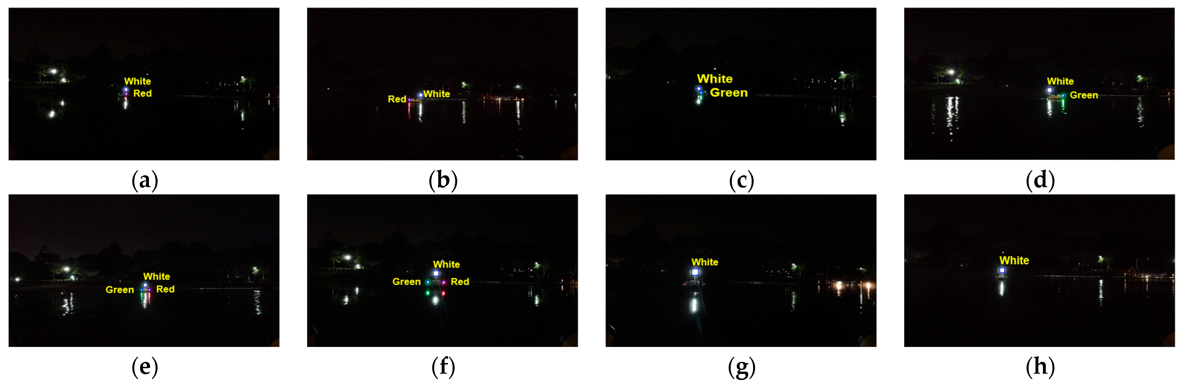
Some recognition results of vessel navigation lights under different observation angles and distances are shown in Figure 19. On this basis, the pixel areas of the recognized navigation-light regions are further extracted for subsequent feature calculation. The pixel area of navigation-light regions in the representative images of Figure 19 is listed in Table 3.

6.3.2. Encounter Situation Recognition

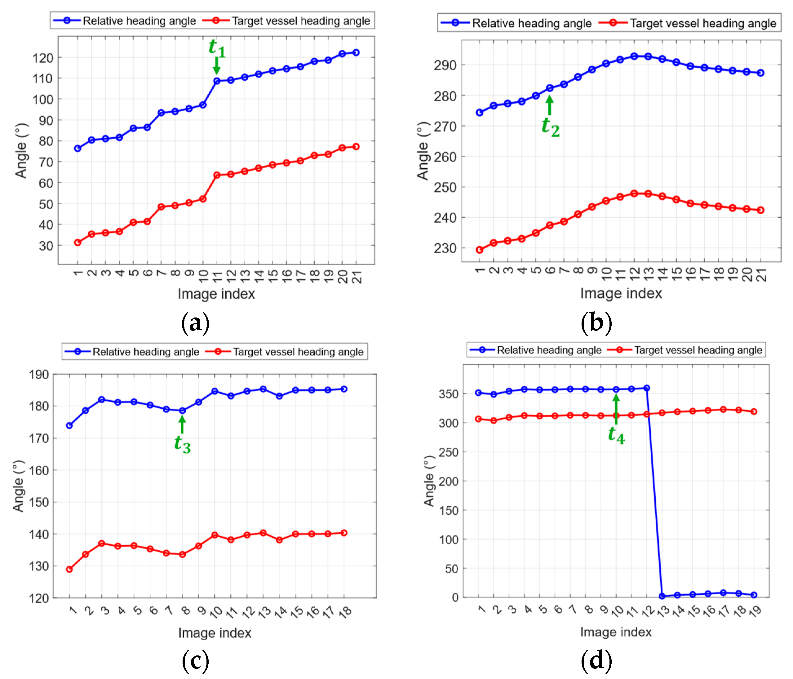
Figure 20 shows the heading angles of the target vessel and the heading intersection angle between the target vessel and the own vessel for the trajectories shown in Figure 18. According to the classification rules described in Section 6.2, the ground truth of the encounter situation for each trajectory is determined from the heading intersection angle. Considering the heading measurement accuracy of approximately 1°, the resulting uncertainty in the heading intersection angle is small relative to the classification intervals defined in Section 6.2. Therefore, the effect of the measurement uncertainty on the result of encounter situation recognition is considered trivial.
A statistical analysis is conducted on the recognition results along the four encounter situation trajectories. Using the ground-truth encounter type of each image frame as the reference, a confusion matrix is constructed for the field-experiment images, as shown in Table 4. The image frames that do not satisfy any of the four predefined decision rules are assigned as “Unknown”. It shows that for port-side crossing, starboard-side crossing, head-on, and overtaking, 21, 20, 15, and 19 frames are correctly recognized, respectively, and an overall accuracy of 94.94% is achieved. Correspondingly, recall values for port-side crossing, starboard-side crossing, head-on, and overtaking are 100.00%, 95.24%, 83.33%, and 100.00%, respectively, while the corresponding precision values are 100.00%, 95.24%, 100.00%, and 95.00%, respectively.
The result shows that the recognition errors in the field experiments are limited to a small number of image frames. Specifically, one frame in the starboard-side crossing situation is assigned to “Unknown”, mainly because the pixel-area extraction of the starboard light is unstable during navigation-light recognition, causing the corresponding area-ratio and difference features to fall outside the predefined rule intervals. The remaining errors are mainly concentrated in the head-on situation. This is because the head-on situation is theoretically characterized by strong symmetry, whereas under real nighttime imaging conditions, the extracted navigation-light features are susceptible to factors such as light-intensity variations and segmentation errors, which weaken the expected symmetry-related feature pattern and consequently cause the extracted feature vectors to deviate from the predefined rule intervals, thereby leading to misclassification. Overall, the field experiment verifies the feasibility and effectiveness of the proposed method in practical situations.
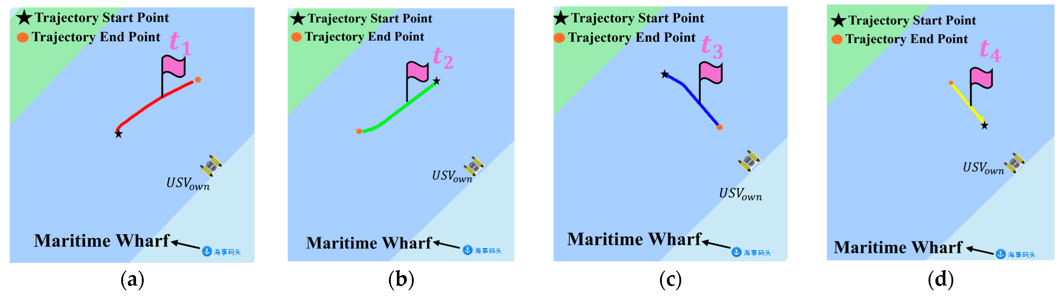
Figure 21 shows the results of encounter situation recognition at particular time instances of the four trajectories. The corresponding visual feature vectors are listed in Table 5.

6.3.3. Ablation Analysis of the Navigation-Light Recognition Method

To verify the necessity and effectiveness of the proposed navigation-light recognition method in real nighttime scenes, ablation experiments are conducted on the field-image dataset described in Section 6.3.1.
According to the practical issues addressed by different parts of the proposed recognition method, three ablation settings are designed, with the proposed method used as the reference, denoted as Group A. In Group B, gamma correction is removed to evaluate its role in improving target–background separability and enhancing background suppression under nighttime dark-background conditions. In Group C, morphological processing and area filtering are removed to evaluate their role in suppressing background interference lights and spurious bright spots. In Group D, aspect ratio and circularity constraints are removed to evaluate the role of geometric constraints in suppressing reflections and irregular pseudo-targets. Except for the removed components, all other processing steps and parameter settings remain unchanged. The results of the ablation experiments are presented in Table 6.
As shown in Table 6, Group A, which adopts the complete navigation-light recognition method, achieves the highest navigation-light recognition rate of 96.20% and an encounter situation recognition rate of 94.94%. In contrast, both performance metrics decrease for Groups B, C, and D. Specifically, the results of Group B indicate that gamma correction improves target extraction under dark-background conditions. The results of Group C indicate that morphological processing and area filtering play important roles in suppressing background interference lights, spurious bright spots, and small pseudo-targets. The results of Group D suggest that aspect ratio and circularity constraints can, to a certain extent, suppress reflections and irregular pseudo-targets, thereby improving the reliability of subsequent encounter situation recognition.
Because the image processing components are coupled within the overall pipeline, the ablation results reported above characterize the variation in overall recognition performance after the removal of specific components, rather than providing a strict quantitative ranking of their individual contributions. Overall, the consistent variation trends of navigation-light recognition and encounter situation recognition further indicate that stable front-end light detection is essential for reliable subsequent feature parameter extraction and encounter situation recognition.

7. Conclusions

This study proposes an image-based method for nighttime recognition of vessel navigation lights and encounter situations. In accordance with the COLREGs, a geometric model of navigation lights and a model of encounter scenarios are established and an idealized navigation-light imaging model is constructed to generate simulated image datasets under different encounter situations. An eleven-dimensional feature vector including area-domain and azimuth-domain features capable of characterizing the encounter situations is designed. Interpretable decision rules were developed to map feature vectors to encounter situations. In addition, an image-processing method combining grayscale features and color features is designed to improve the stability of navigation-light extraction under nighttime interferences. Both simulation and field experiment results support the effectiveness and feasibility of the proposed method under the tested simulation assumptions and field conditions.
The study still has several limitations, which will be addressed in future work:
  • Dataset aspect: The field experiments were conducted with small USVs with a three-light configuration under mild lake conditions. Future work will involve extensive data collection from collaborating institutions, covering a wider range of vessel types, navigation-light configurations and sailing environments for validation.
  • Method aspect: The present method is based on a simulated dataset and traditional machine vision methods for computational efficiency. Its robustness under adverse conditions such as fog, rain, low visibility, wave-induced disturbance, and blurred navigation lights remains limited. Future work will therefore investigate image-enhancement methods, temporal consistency across consecutive frames, and the integration of learning-based techniques with extended datasets. Field experimental datasets will be used to verify, refine, and improve the feature vectors, which can serve as prior rules for learning-based methods to reduce computational load.
  • Application aspect: This study only considers the basic case of encounter situation recognition between the own vessel and a single target vessel. Multi-vessel encounters, which require multi-target light grouping and separate encounter judgment for each target vessel, remain beyond the current scope and will be studied in future work.

Author Contributions

Conceptualization, J.W.; methodology, R.H.; software, R.H.; validation, R.H.; formal analysis, R.H.; investigation, R.H., Y.T. (Yu Tian) and Y.T. (Yining Tian); resources, X.Z., J.W., G.W., Y.T. (Yu Tian) and Y.T. (Yining Tian); data curation, R.H.; writing—original draft preparation, R.H.; writing—review and editing, R.H., X.Z. and J.W.; visualization, R.H.; supervision, X.Z. and J.W.; project administration, J.W. and Y.T. (Yu Tian); funding acquisition, G.W. All authors have read and agreed to the published version of the manuscript.

Funding

This study was supported by the National Natural Science Foundation of China, grant number 52271322.

Institutional Review Board Statement

Not applicable.

Informed Consent Statement

Not applicable.

Data Availability Statement

The original contributions presented in this study are included in this article. Further inquiries can be directed to the corresponding author.

Acknowledgments

The authors thank the anonymous reviewers for suggesting valuable improvements for this paper.

Conflicts of Interest

Author Yu Tian and Yining Tian were employed by the company Shanghai Auto Subsea Vehicles Inc. The remaining authors declare that the research was conducted in the absence of any commercial or financial relationships that could be construed as a potential conflict of interest.

References

  1. Kim, T.E.; Perera, L.P.; Sollid, M.P.; Batalden, B.M.; Sydnes, A.K. Safety challenges related to autonomous ships in mixed navigational environments. WMU J. Marit. Aff. 2022, 21, 141–159. [Google Scholar] [CrossRef]
  2. Liu, Y.Q.; Tang, H.; Wang, X.A.; Guo, L.F.; Li, A.Y.; Zhong, C.W. Research on the application of large language models for ship navigation decision-making. Chin. J. Ship Res. 2025, 20, 90–100. [Google Scholar] [CrossRef]
  3. Wynn, T.; Howarth, P.A.; Kunze, B.R. Night-time lookout duty: The role of ambient light levels and dark adaptation. J. Navig. 2012, 65, 589–602. [Google Scholar] [CrossRef]
  4. Lei, J.; Sun, Y.; Wu, Y.; Zheng, F.; He, W.; Liu, X. Association of AIS and radar data in intelligent navigation in inland waterways based on trajectory characteristics. J. Mar. Sci. Eng. 2024, 12, 890. [Google Scholar] [CrossRef]
  5. Hoehner, F.; Langenohl, V.; el Moctar, O.; Schellin, T.E. Scenario-based sensor selection for autonomous maritime systems: A multi-criteria analysis of sensor configurations for situational awareness. J. Mar. Sci. Eng. 2025, 13, 2008. [Google Scholar] [CrossRef]
  6. Li, K.X.; Pan, H.H.; Wang, G.Q.; Zheng, G.H.; Huang, H.G. Collision warning and accident backtracking algorithm for fishing vessels based on large-scale AIS data. Ship Mater. Mark. 2023, 31, 10–13. [Google Scholar] [CrossRef]
  7. Jiang, L.H.; Liu, T.; Wang, X.S.; Xie, W.D. Method for extracting ship collision avoidance behavior in AIS data. Ship Sci. Technol. 2025, 47, 141–147. [Google Scholar]
  8. Jiang, L.H.; Zheng, Z.Y.; Qi, L. Extraction of ship-encounter information from AIS data. China Sci. Pap. 2017, 12, 802–805. [Google Scholar]
  9. Murray, B.; Perera, L.P. Ship behavior prediction via trajectory extraction-based clustering for maritime situation awareness. J. Ocean Eng. Sci. 2022, 7, 1–13. [Google Scholar] [CrossRef]
  10. Kim, C.; Hong, S.; Park, J.; Choi, J.; Kim, H.J. Generation of navigation database using AIS data for remote situational awareness of coastal vessels. Appl. Ocean Res. 2025, 154, 104401. [Google Scholar] [CrossRef]
  11. Mazzarella, F.; Vespe, M.; Alessandrini, A.; Tarchi, D.; Aulicino, G.; Vollero, A. A novel anomaly detection approach to identify intentional AIS on-off switching. Expert Syst. Appl. 2017, 78, 110–123. [Google Scholar] [CrossRef]
  12. Hague, E.; Walters, A.E.M.; Moscrop, A.; Steel, E.; Dyke, K.; Hartny-Mills, L.; Lomax, A.; Dudley, R.; Garrard, P.; Hampson, J.; et al. AIS data underrepresents vessel traffic around coastal Scotland. Mar. Policy 2025, 178, 106719. [Google Scholar] [CrossRef]
  13. Yan, B.; Sun, S.C.; Li, Z.Q. Research on the application of Automatic Identification System (AIS) in pilotage dispatching. Tianjin Navig. 2025, 1, 9–12. [Google Scholar] [CrossRef]
  14. Fukuda, G.; Tamaru, H.; Kubo, N.; Shoji, R. A study on AIS positional error analysis and transmission frequency requirements of attitude data for future vessel monitoring. J. Navig. 2024, 77, 677–694. [Google Scholar] [CrossRef]
  15. Liang, M.C.; Wang, S.Z. Optimization simulation research of marine radar plotting function based on genetic algorithm. Ship Sci. Technol. 2024, 46, 138–142. [Google Scholar]
  16. Villa, J.; Aaltonen, J.; Koskinen, K.T. Path-following with lidar-based obstacle avoidance of an unmanned surface vehicle in harbor conditions. IEEE/ASME Trans. Mechatron. 2020, 25, 1812–1820. [Google Scholar] [CrossRef]
  17. Bounaceur, H.; Khenchaf, A.; Le Caillec, J.-M. Analysis of small sea-surface targets detection performance according to airborne radar parameters in abnormal weather environments. Sensors 2022, 22, 3263. [Google Scholar] [CrossRef]
  18. Ma, F.; Kang, Z.; Chen, C.; Sun, J.; Xu, X.B.; Wang, J. Identifying ships from radar blips like humans using a customized neural network. IEEE Trans. Intell. Transp. Syst. 2024, 25, 7187–7205. [Google Scholar] [CrossRef]
  19. Li, L.; Jiang, L.; Zhang, J.; Wang, S.; Chen, F. A complete YOLO-based ship detection method for thermal infrared remote sensing images under complex backgrounds. Remote Sens. 2022, 14, 1534. [Google Scholar] [CrossRef]
  20. Xu, C.J.; Ji, Y.K.; Wang, K. Pose estimation and recognition of nearshore vessels based on infrared thermal imaging technology. Port Technol. 2024, 2, 1–5. [Google Scholar]
  21. Zhang, Y.C.; Chen, Y.M.; Fu, X.B.; Luo, C. The research on the effect of atmospheric transmittance for the measuring accuracy of infrared thermal imager. Infrared Phys. Technol. 2016, 77, 375–381. [Google Scholar] [CrossRef]
  22. Liu, Y.; Dong, L.; Xu, W. Infrared and visible image fusion for shipborne electro-optical pod in maritime environment. Infrared Phys. Technol. 2023, 128, 104526. [Google Scholar] [CrossRef]
  23. Yang, Y.; Yang, F.; Sun, L.; Xiang, T.; Lv, P. Multi-target association algorithm of AIS-radar tracks using graph matching-based deep neural network. Ocean Eng. 2022, 266, 112208. [Google Scholar] [CrossRef]
  24. Talpur, K.; Hasan, R.; Gocer, I.; Ahmad, S.; Bhuiyan, Z. AI in maritime security: Applications, challenges, future directions, and key data sources. Information 2025, 16, 658. [Google Scholar] [CrossRef]
  25. Chen, X.; Qi, L.; Yang, Y.; Luo, Q.; Postolache, O.; Tang, J.; Wu, H. Video-based detection infrastructure enhancement for automated ship recognition and behavior analysis. J. Adv. Transp. 2020, 2020, 7194342. [Google Scholar] [CrossRef]
  26. Xu, X.; Chen, X.; Wu, B.; Wang, Z.; Zhen, J. Exploiting high-fidelity kinematic information from port surveillance videos via a YOLO-based framework. Ocean Coast. Manag. 2022, 222, 106117. [Google Scholar] [CrossRef]
  27. Ding, H.; Weng, J.; Shi, K. Real-time assessment of ship collision risk using image processing techniques. Appl. Ocean Res. 2024, 153, 104241. [Google Scholar] [CrossRef]
  28. Jiang, Z.; Zhang, L.; Li, W. A machine vision method for the evaluation of ship-to-ship collision risk. Heliyon 2024, 10, e25105. [Google Scholar] [CrossRef]
  29. Liu, S.H. Research on Ship Encounter Situation Recognition Technology Based on Deep Learning. Master’s Thesis, Dalian Maritime University, Dalian, China, 2023. [Google Scholar]
  30. Helgesen, Ø.K.; Thyri, E.H.; Brekke, E.; Stahl, A.; Breivik, M. Experimental validation of camera-based maritime collision avoidance for autonomous urban passenger ferries. Model. Identif. Control 2023, 44, 55–68. [Google Scholar] [CrossRef]
  31. Nishina, T.; Shimizu, E. A preliminary study on obstacle detection system for night navigation. In Proceedings of the 2020 IEEE/SICE International Symposium on System Integration (SII), Honolulu, HI, USA, 12–15 January 2020; pp. 1107–1112. [Google Scholar] [CrossRef]
  32. Liu, L.; Liu, G.; Chu, X.M.; Jiang, Z.L.; Zhang, M.Y.; Ye, J. Ship detection and tracking in nighttime video images based on the method of LSDT. J. Phys. Conf. Ser. 2019, 1187, 042074. [Google Scholar] [CrossRef]
  33. Chen, C.; Hu, S.T.; Ma, F.; Zhao, X.Z.; Wei, Y.N.; Shu, Z.C. Ship Contour: A novel instance segmentation approach based on Snake and attention mechanism. Chin. J. Ship Res. 2025, 20, 307–320. [Google Scholar] [CrossRef]
  34. Hu, X. Recognition Method of Marine Navigation Ship Lights Based on Video Analysis. Master’s Thesis, Dalian Maritime University, Dalian, China, 2021. [Google Scholar]
  35. Bi, Q.; Wang, M.; Huang, Y. Ship collision avoidance navigation signal recognition via vision sensing and machine forecasting. IEEE Trans. Intell. Transp. Syst. 2023, 24, 11743–11755. [Google Scholar] [CrossRef]
  36. Gao, X.; Zhao, Y. Research on methods for the recognition of ship lights and the autonomous determination of the types of approaching vessels. J. Mar. Sci. Eng. 2025, 13, 643. [Google Scholar] [CrossRef]
  37. Qiao, Y.; Gao, X.; Zhao, Y. Ship’s lights identification based on lightweight YOLOv8n. J. Dalian Marit. Univ. 2025, 51, 82–91. [Google Scholar] [CrossRef]
  38. United Nations. Convention on the International Regulations for Preventing Collisions at Sea, 1972 (COLREGs). Available online: https://treaties.un.org/doc/publication/unts/volume%201050/volume-1050-i-15824-english.pdf (accessed on 11 April 2026).
Figure 1. Navigation lights of a vessel at night.
Jmse 14 00761 g001
Figure 2. Horizontal light arcs of vessel navigation lights. (The dashed line indicates the fore-and-aft centerline of the vessel. The red and green sectors represent the port and starboard sidelights, respectively, while the white sectors indicate the masthead light and stern light visibility arcs).
Jmse 14 00761 g002
Figure 3. Navigation lights of the target vessel in the four encounter situations. (a) Head-on; (b) port-side crossing. (c) Starboard-side crossing; (d) overtaking. (The red and green dots denote the port and starboard sidelights, respectively, while the white dots denote the masthead and stern lights).
Jmse 14 00761 g003
Figure 4. Structural diagram of navigation lights.
Jmse 14 00761 g004
Figure 5. Schematic diagram of navigation-light imaging: (a) five-light configuration; (b) three-light configuration.
Jmse 14 00761 g005
Figure 6. Scenario models for encounter situations. (a) Stationary target vessel and moving own vessel; (b) stationary own vessel and moving target vessel.
Jmse 14 00761 g006
Figure 7. Images of navigation lights in four typical encounter situations: (a) head-on ( α = 0 ° ); (b) starboard-side crossing ( α = 90 ° ); (c) port-side crossing ( α = 270 ° ); (d) overtaking ( α = 180 ° ). (The red and green light spots represent the port and starboard sidelights, respectively, and the white light spots represent the white navigation lights. u / p x and v / p x denote the horizontal and vertical pixel coordinates, respectively, and α denotes the observation angle).
Jmse 14 00761 g007
Figure 8. Area-domain feature curves of five-light and three-light configurations in different encounter situations. (a) Area-ratio feature curves for head-on; (b) Area-difference feature curves for head-on; (c) Area-ratio feature curves for starboard-side crossing; (d) Area-difference feature curves for starboard-side crossing; (e) Area-ratio feature curves for port-side crossing; (f) Area-difference feature curves for port-side crossing; (g) Stern-light area variation rate for the five-light configuration; (h) Stern-light area variation rate for the three-light configuration.
Jmse 14 00761 g008
Figure 9. Azimuth-angle feature curves in different encounter situations: (a) head-on; (b) starboard-side crossing; (c) port-side crossing.
Jmse 14 00761 g009
Figure 10. Real image of navigation lights.
Jmse 14 00761 g010
Figure 11. Gamma-corrected image.
Jmse 14 00761 g011
Figure 12. Grayscale-based navigation-light image segmentation.
Jmse 14 00761 g012
Figure 13. Navigation-light image segmentation based on color features.
Jmse 14 00761 g013
Figure 14. Matching result.
Jmse 14 00761 g014
Figure 15. Field experimental scene.
Jmse 14 00761 g015
Figure 16. Experimental setup for the navigation lights.
Jmse 14 00761 g016
Figure 17. The four designed encounter situations: (a) head-on; (b) port-side crossing; (c) starboard-side crossing; (d) overtaking. (The blue dashed lines indicate the original heading of the own vessel, the green dashed lines indicate the original heading of the target vessel, and the yellow dashed lines indicate the motion paths of the give-way vessel. The arrows indicate the corresponding directions of motion).
Jmse 14 00761 g017
Figure 18. Actual trajectories of USV obj in the field experiments. (Numbers ①–④ indicate the four experimental trajectories, and the label “Maritime Wharf” indicates the dock shown on the base map).
Jmse 14 00761 g018
Figure 19. Performance of navigation-light recognition under different angles and distances. Subfigures (ah) show selected image frames with recognized navigation-light labels. The yellow text labels indicate the recognized navigation-light colors.
Jmse 14 00761 g019
Figure 20. Heading angles of the target vessel and heading intersection angles in different encounter situations: (a) port-side crossing; (b) starboard-side crossing; (c) head-on; (d) overtaking.
Jmse 14 00761 g020
Figure 21. Results of encounter situation recognition at different time instants. Subfigures (ad) show the positions of U S V o b j on the actual trajectories at time instants t 1 t 4 , respectively, where the flag symbols indicate the selected time instants. Subfigures (eh) show the corresponding navigation-light recognition results used for encounter situation recognition. The yellow text labels corresponding to t 1 t 4 denote the recognized navigation-light colors and the corresponding encounter situations.
Jmse 14 00761 g021aJmse 14 00761 g021b
Table 1. Classification accuracies under different distances.
Distance   D /m Number   of   Frames   N D A c c / %
20017498.3
25017496.6
30017496.6
Table 2. Overall confusion matrix of encounter situation recognition results under simulation conditions.
Predicted/Ground TruthPort-Side CrossingStarboard-Side CrossingHead-onOvertaking
Port-side crossing151000
Starboard-side crossing015100
Head-on00340
Overtaking000171
Unknown5550
Table 3. Statistics of pixel areas of navigation-light regions in different images.
Image IDabcdefgh
A p o r t / pixels 148.8144126296.4
A s t a r / pixels 130.5388.02132.24363.66
A a l l / pixels 197.67232.65186.4458226.05487.08706.2341.88
Table 4. Confusion matrix of encounter situation recognition results in the field experiments.
Predicted/Ground TruthPort-Side CrossingStarboard-Side CrossingHead-onOvertaking
Port-side crossing21000
Starboard-side crossing02010
Head-on00150
Overtaking00119
Unknown0110
Table 5. Values of feature vector at different time instants.
Time x R / M x G / M Δ R G Δ R M Δ G M Δ a f t / ° Δ p o r t / ° Δ s t a r / ° Δ f o r e / ° θ s t e r n / ° Recognition Result
t 1 00.768−1.000−1.000−0.131−5.18360−2.320360Port-side crossing
t 2 0.56401.000−0.279−1.00017.814.173600360Starboard-side crossing
t 3 0.4850.587−0.087−0.347−0.268−0.79−2.82.930360Head-on
t 4 00000360360360360−5.64overtaking
Table 6. Ablation results of the navigation-light recognition method.
GroupGamma CorrectionMorphological Processing and Area FilteringAspect Ratio and Circularity Constraints R i m g Classification Accuracy %
A96.2094.94
B×65.8258.23
C×43.0439.87
D×79.7571.14
Note: “√” indicates that the corresponding processing step is included, whereas “×” indicates that the corresponding processing step is not included.
Disclaimer/Publisher’s Note: The statements, opinions and data contained in all publications are solely those of the individual author(s) and contributor(s) and not of MDPI and/or the editor(s). MDPI and/or the editor(s) disclaim responsibility for any injury to people or property resulting from any ideas, methods, instructions or products referred to in the content.